

Page 1
Installation Instructions
PROFIBUS/PROFINET Decoupling Kit
®
VLT
AutomationDrive FC 360
PROFIBUS/PROFINET decoupling kit for mounting the control
cassette with PROFIBUS and control cassette with PROFINET.
Mount the control cassette on the frequency converter before
mounting the PROFIBUS/PROFINET decoupling kit.
Items Supplied
For each control cassette with PROFIBUS or control cassette
with PROFINET, 2 decoupling kits are supplied in the package.
Install the correct kit based on the enclosure size of the
frequency converter.
Code number Items supplied
132B0274 PROFIBUS/PROFINET decoupling kit for enclosure
sizes J1–J5, containing the following items:
Decoupling plate.
•
2 M3x6 screws.
•
132B0286 PROFIBUS/PROFINET decoupling kit for enclosure
sizes J6 and J7, containing the following items:
Decoupling plate.
•
2 M3x6 screws.
•
Table 1.1 Items Supplied
Voltage [V] Minimum waiting time (minutes)
415
380–480 0.37–7.5 kW 11–75 kW
High voltage may be present even when the warning LEDs are o!
Tab le 1. 2 D isc har ge Tim e
Refer to the quick guide for detailed information about safe
installation of the frequency converter.
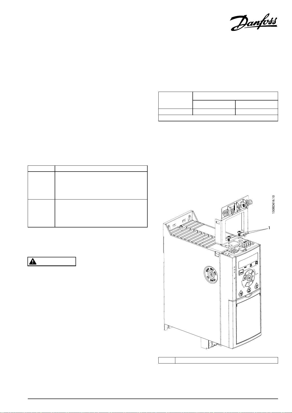
Mounting
1. Place the decoupling plate on the control cassette
that is mounted on the frequency converter, and
fasten the plate using 2 screws (supplied). Tightening
torque 0.7–1.0 Nm.
Safety Instructions
WARNING
DISCHARGE TIME
The frequency converter contains DC-link capacitors, which
can remain charged even when the frequency converter is
not powered. Failure to wait the specied time after power
has been removed before performing service or repair work,
could result in death or serious injury.
Disconnect AC mains, permanent magnet type
•
motors, and remote DC-link power supplies,
including battery back-ups, UPS, and DC-link
connections to other frequency converters.
Wait for the capacitors to discharge fully, before
•
performing any service or repair work. The duration
of waiting time is specied in Ta b l e 1 . 2 .
1Screws
Illustration 1.1 Fasten the Plate with Screws
Danfoss A/S © 05/2015 All rights reserved. MI06L302
Page 2
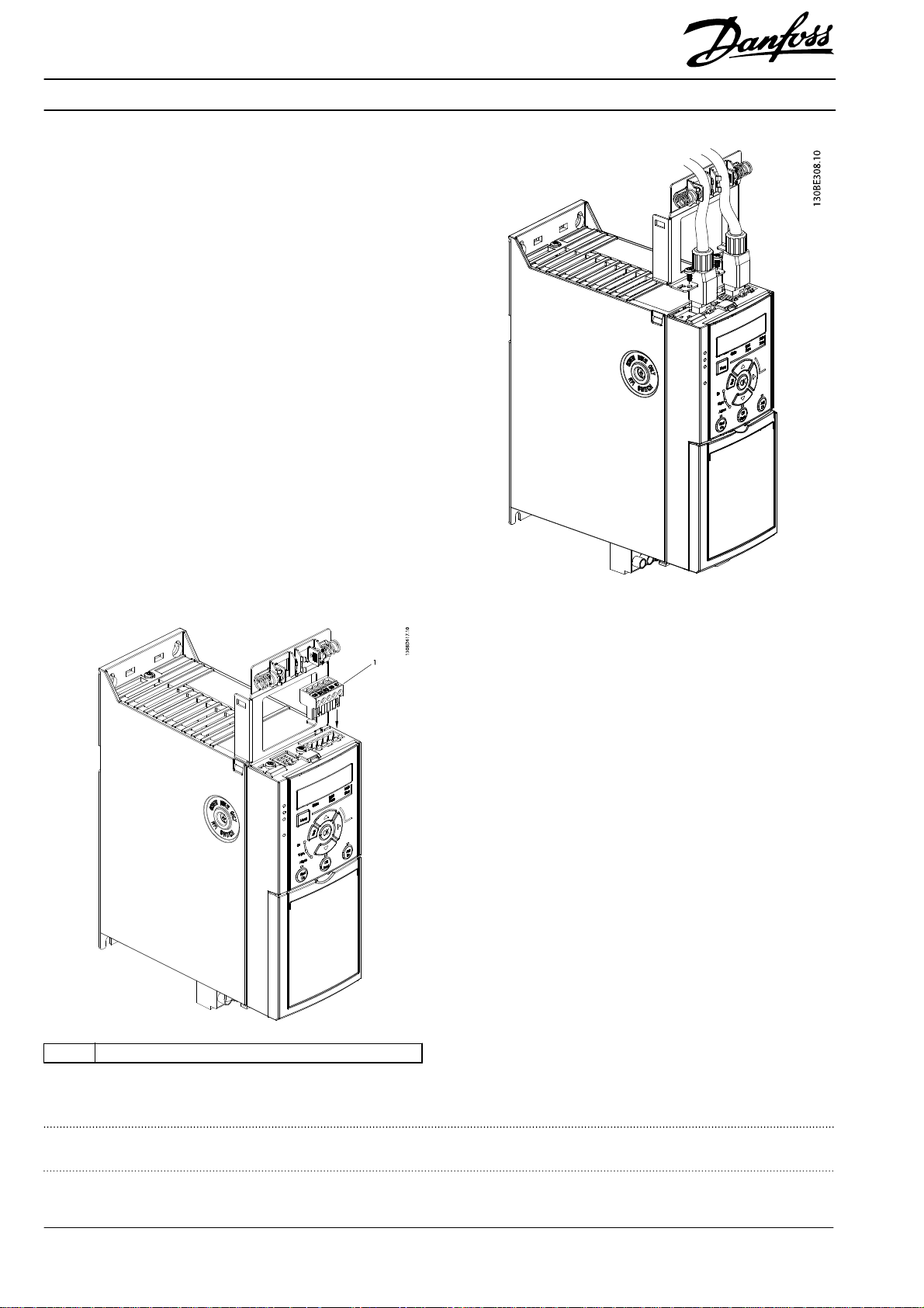
2. 2a PROFIBUS
a. Push PROFIBUS cables into the
b. Place the cables between the
c. Push the 5-pin connector into the
2b PROFINET
a. Push the Ethernet cable
b. Place Ethernet cables between the
slots of the 5-pin connector, and
tighten the screws. Tightening
torque 0.3–0.6 Nm.
spring-loaded metal clamps, to
establish contact and mechanical
xation between cable shielding
and the clamps.
control cassette, as shown in
Illustration 1.2.
connectors into the slots on the
control cassette.
spring loaded metal clamps, as
shown in Illustration 1.3, to
establish mechanical xation and
electrical contact between the
cable and ground.
Illustration 1.3 Place Ethernet Cables between Clamps
1 5-pin connector for PROFIBUS
Illustration 1.2 Push the Connector into Place
Danfoss can accept no responsibility for possible errors in catalogues, brochures and other printed material. Danfoss reserves the right to alter its products without notice. This also applies to products already on
order provided that such alterations can be made without subsequential changes being necessary in specifications already agreed. All trademarks in this material are property of the respective companies. Danfoss
and the Danfoss logotype are trademarks of Danfoss A/S. All rights reserved.
Danfoss A/S
Ulsnaes 1
DK-6300 Graasten
vlt-drives.danfoss.com
MI06L302132R0209 05/2015
*MI06L302*
 Loading...