

Page 1

Technical Information
Joystick
Prof 1, PVRE and PVRET
www.danfoss.com
Page 2
Technical Information
Prof 1, PVRE and PVRET Joystick
Revision history Table of revisions
Date Changed Rev
December 2020 Added clarifying note on page 19 0302
July 2019 Added Standard and extended versions connections 0201
June 2018 Updated layout to Engineering Tomorrow design 0102
March 2008 First edition 0101
Changed document number from 'BC00000069' to 'BC152886484305' XX
2 | © Danfoss | December 2020 BC152886484305en-000302
Page 3

Technical Information
Prof 1, PVRE and PVRET Joystick
Contents
General
Application..........................................................................................................................................................................................4
Mechanical Design...........................................................................................................................................................................4
Main Function Module................................................................................................................................................................... 4
Connector............................................................................................................................................................................................4
Direction Switches........................................................................................................................................................................... 5
Neutral Position Switch..................................................................................................................................................................5
Cables................................................................................................................................................................................................... 5
Prof Joysticks
Handle / Top functions...................................................................................................................................................................7
Base module.......................................................................................................................................................................................7
Cable..................................................................................................................................................................................................... 8
Prof 1
Color Band...........................................................................................................................................................................................9
Proportional Modules.....................................................................................................................................................................9
Push Buttons....................................................................................................................................................................................10
Location and Orientation of Modules.................................................................................................................................... 10
Electronic Modules........................................................................................................................................................................11
Basic...............................................................................................................................................................................................11
Standard.......................................................................................................................................................................................11
Extended......................................................................................................................................................................................12
CAN-enabled..............................................................................................................................................................................14
Basic version connections ..........................................................................................................................................................15
Standard and extended versions connections....................................................................................................................16
Technical Data.................................................................................................................................................................................17
Prof1 dimensions........................................................................................................................................................................... 18
Examples of Use..............................................................................................................................................................................19
Basic version used with controller......................................................................................................................................19
Standard program......................................................................................................................................................................... 20
Selection Overview........................................................................................................................................................................22
Standard program details...........................................................................................................................................................26
Prof 1 Joystick Specification.......................................................................................................................................................27
PVRE series 2
Versions............................................................................................................................................................................................. 28
Location and Orientation of Functions..................................................................................................................................29
Connections.....................................................................................................................................................................................30
Technical Data.................................................................................................................................................................................30
Dimensions.......................................................................................................................................................................................32
Examples of Use..............................................................................................................................................................................33
PVRE....................................................................................................................................................................................................35
PVRET series 2
Version............................................................................................................................................................................................... 36
PVRET version connections........................................................................................................................................................ 36
Technical Data.................................................................................................................................................................................36
PVRET version dimensions..........................................................................................................................................................37
Examples of Use..............................................................................................................................................................................37
©
Danfoss | December 2020 BC152886484305en-000302 | 3
Page 4
Technical Information
Prof 1, PVRE and PVRET Joystick
General
Application
PVRE, PVRET and Prof joysticks from Danfoss are generally used together with PVGs and PVEs, but can be
used in any application. A complete range of joysticks from the simple PVRE handle with X-Y functions to
the Prof 1 ergonomic handle with rollers and pushbuttons are available.
Mechanical Design
All handle variants share the same mechanical base to which the electronics are mounted. The mounting
flange of the joystick is an integrated part of the mechanical base, which also contains a linkage that
transfers handle movement to the electronics. The linkage also includes neutral positioning springs.
The neutral positioning springs are designed to ensure a smooth return of the handle into neutral
position. The maximum spring force is optimised to be just strong enough to keep the handle in position,
even during operation in rough terrain, without interfering with the operation of the joystick or impairing
it’s ergonomic characteristics.
Spring force 8-10 N
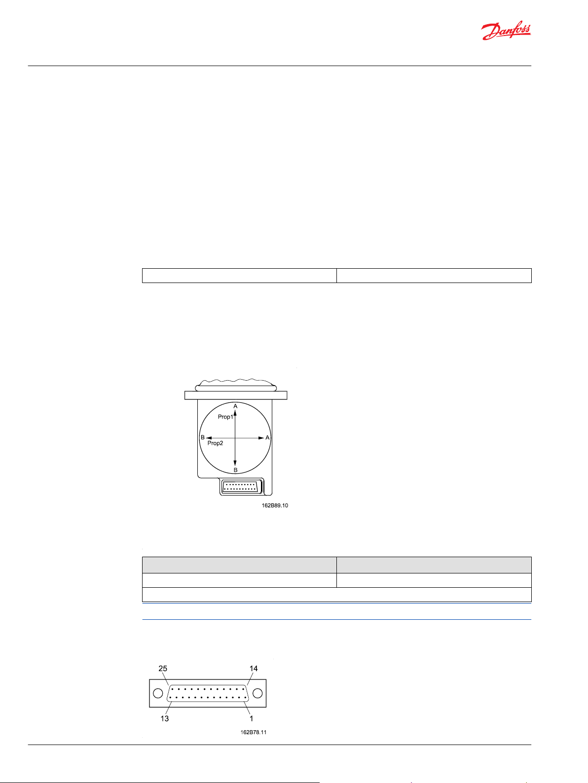
Main Function Module
(Prop1 and Prop2)
The primary functions of the joystick are defined as its X and Y directions.
Main functions are potentiometers with integrated direction switches.
Each function has a working angle of ±18°.
Signal range Neutral signal
25% – 75% 50%
of supply voltage
When moving the handle diagonally the maximum signal range is not available.
Connector
All joysticks come with a common 25 pin male SUB-D connector with M3 screws. (MIL - DTL - 24308)
4 | © Danfoss | December 2020 BC152886484305en-000302
Page 5
Technical Information
Prof 1, PVRE and PVRET Joystick
General
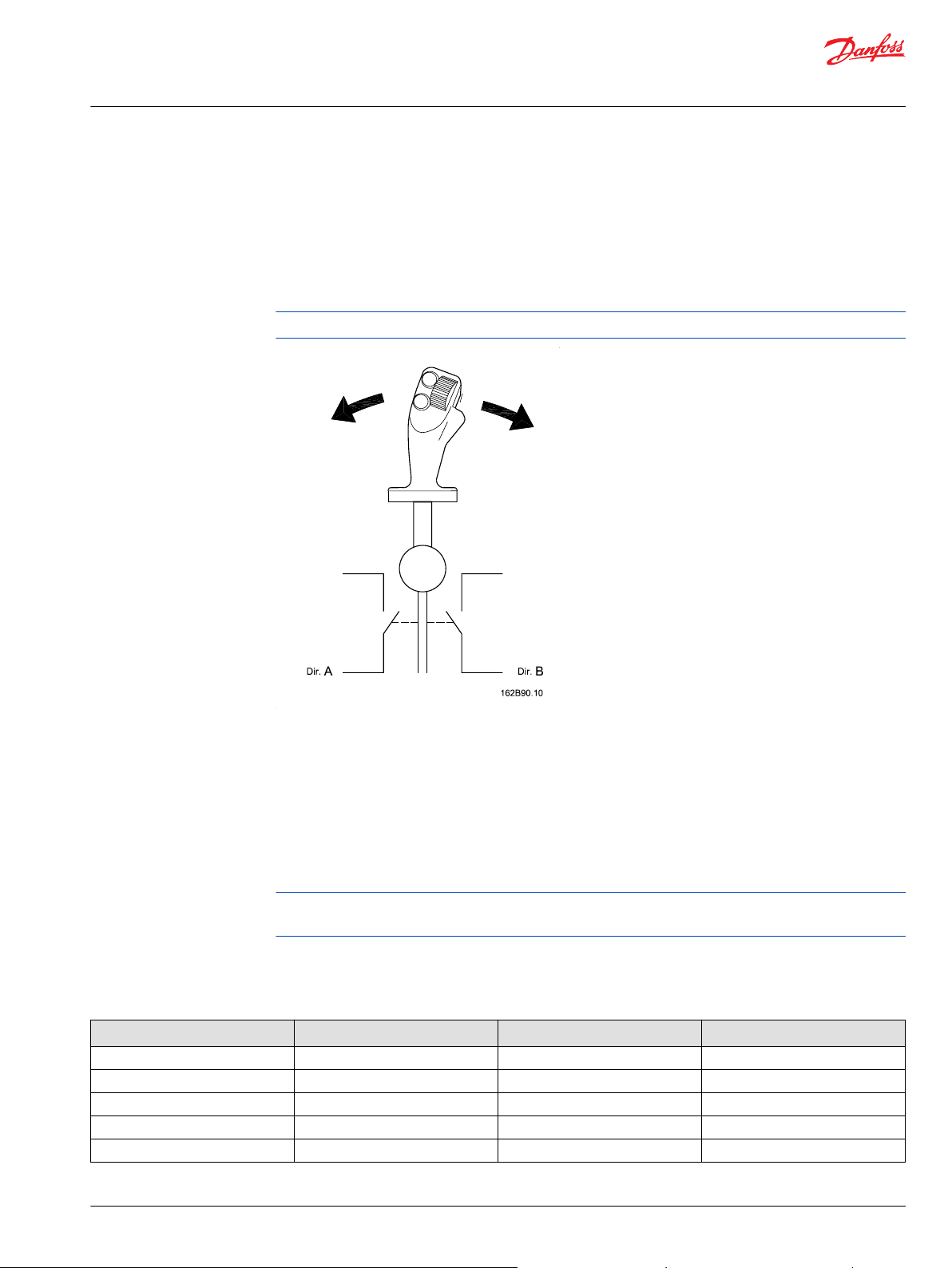
Direction Switches
Proportional modules have integrated direction switches. One switch is activated when the module is
moved in the A direction, the other is activated when the module is moved in the B direction.
The direction switches are used to activate the neutral position switch, and with some electronic modules
the direction switch outputs are available in the connector. (See details about electronics.)
There is a dead band in the joystick of approximately 1.5° before the direction switches are activated.
The direction switches are independant from the signal voltage
Neutral Position Switch
The neutral position switch can supply up to 3 PVEs or other devices (see electrical details), and functions
as both a power save and a safety switch.
The switch is only activated when one or more of the proportional modules are activated.
The operation of the neutral position switch is dependant on signals from the direction switches.
Danfoss recommends that the neutral position switch be used to the greatest possible extent.
When using the neutral position switch all three UDC wires as well as all three Neutral Switch wires must
be connected.
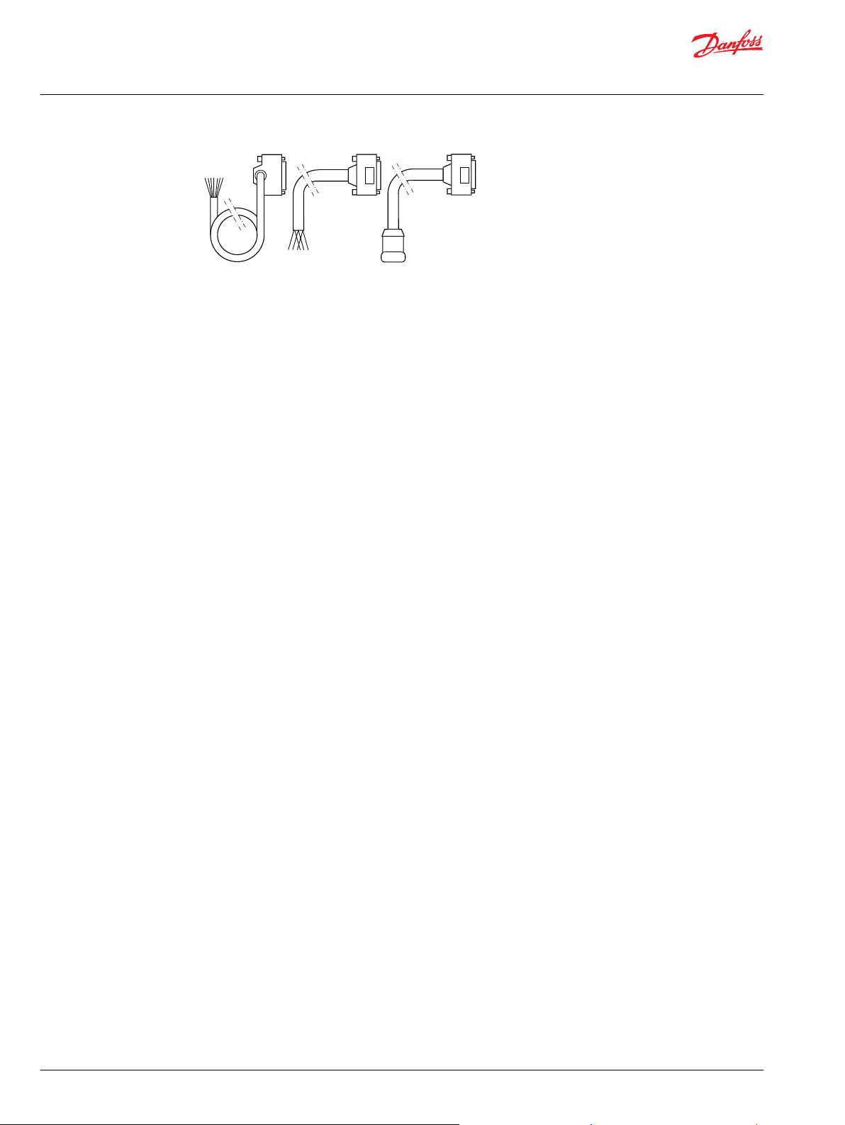
Cables
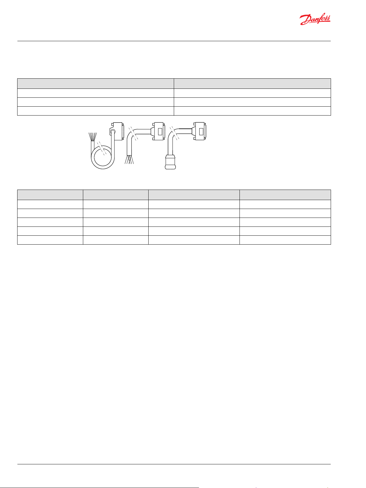
For compatibility with different applications, a selection of mating cables are available:
Code no. 162B…. Length mm [in] Plug type Type
6013 4000 [157] Leads Vertical SUB-D
6014 4000 [157] Leads Horizontal Sub-D
6015 500 [19] Clipper –
6016 230 [9] TrimTrio –
6017 230 [9] Tabs PVRE compatibility
©
Danfoss | December 2020 BC152886484305en-000302 | 5
Page 6
kwa1385300991617
Technical Information
Prof 1, PVRE and PVRET Joystick
General
6 | © Danfoss | December 2020 BC152886484305en-000302
Page 7
Technical Information
Prof 1, PVRE and PVRET Joystick
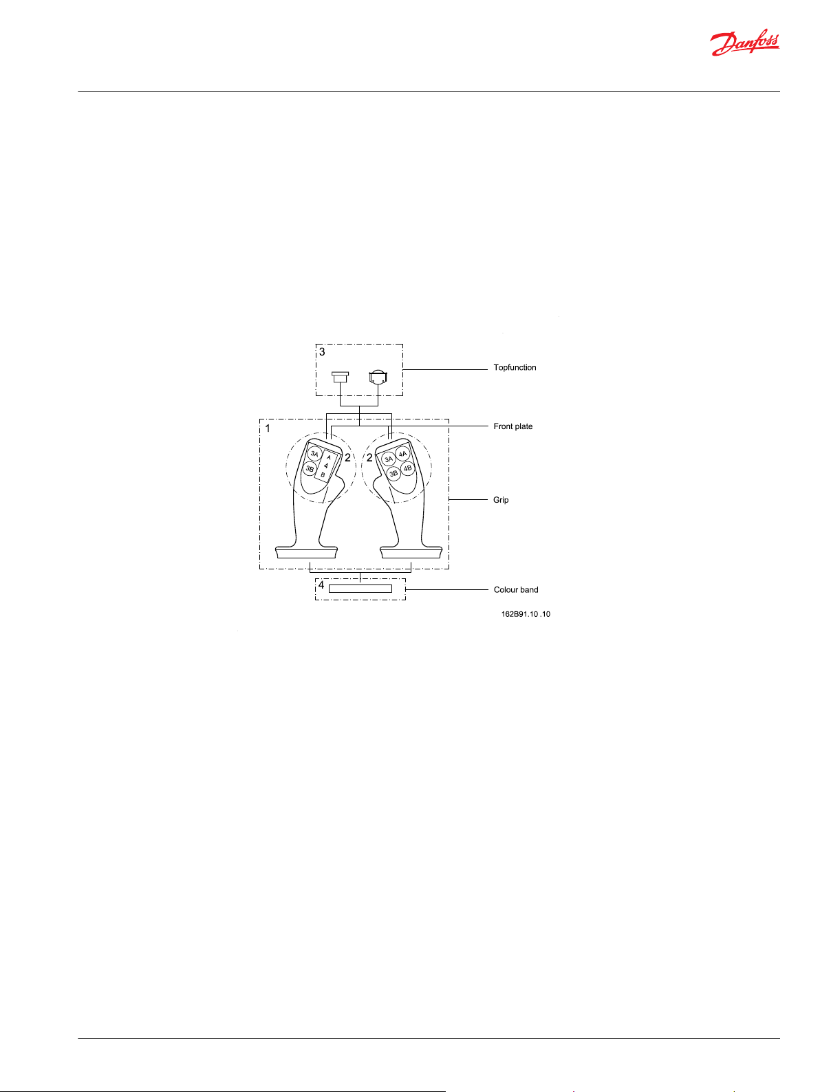
Prof Joysticks
The Prof family of joysticks is built around a series of modules that can be combined in various ways to
create the joystick that best fits the application.
Each joystick has a base module with proportional functions (X & Y); a colour band for decoration and
identity, a handle, and depending on handle selection, a number of pushbuttons and/or proportional
functions.
Handle / Top functions
To provide optimum user comfort, a selection of handles is available. Each handle offers a choice of push
buttons and / or proportional functions positioned for ease of use and comfort.
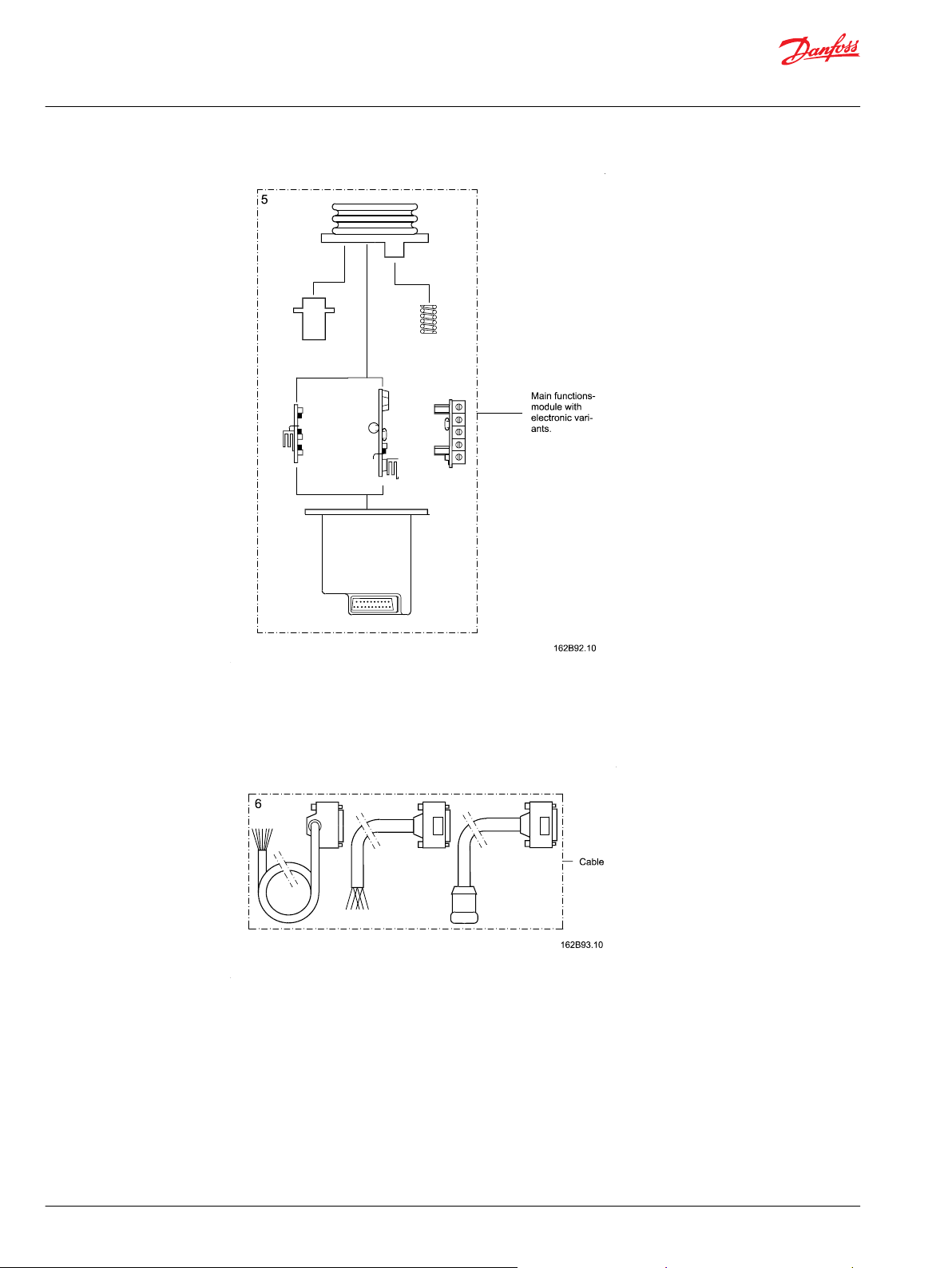
Base module
A number of electronic modules provide various performance levels to cater for different needs in
different applications.
©
Danfoss | December 2020 BC152886484305en-000302 | 7
Page 8
Technical Information
Prof 1, PVRE and PVRET Joystick
Prof Joysticks
Cable
For easy integration into existing applications cables with different connectors are available as
accessories, see page 5.
8 | © Danfoss | December 2020 BC152886484305en-000302
Page 9
Technical Information
Prof 1, PVRE and PVRET Joystick
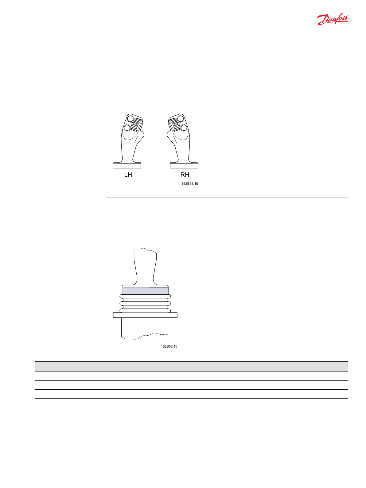
Prof 1
A professional handle for intensive operation; with a forward-leaning, curved, ergonomic shape. The
leather-like grained surface allows the palm of the hand to breathe during operation.
The Prof 1 handle can be fitted with up to seven push buttons, or up to two proportional functions with
up to five push buttons.
For location and combination of function modules see the overview.
The flush alignment between front plate and grip can’t be guaranteed, however, an inspection is made to
insure there are no air cavities.
Color Band
Colors
Yellow
Black
Red
A choice of colors is available for the band at the base of the handle.
Proportional Modules
The roller function module is a spring centred potentiometer with integrated direction switches.
Working angle: ±42°
Direction switch angle: 3.5 ±2°
©
Danfoss | December 2020 BC152886484305en-000302 | 9
Page 10
Technical Information
Prof 1, PVRE and PVRET Joystick
Prof 1
Signal range Neutral signal
25% – 75% 50%
of supply voltage
Push Buttons
The handle can be fitted with up to seven independent On/Off functions.
The buttons are protected against shocks and unintentional activation by a high collar.
Colors
Yellow
Black
Red
Grey
Location and Orientation of Modules
10 | © Danfoss | December 2020 BC152886484305en-000302
Page 11
Technical Information
Prof 1, PVRE and PVRET Joystick
Prof 1
Electronic Modules
The electronic modules are available with four different performance levels: Basic, Standard, Extended,
and CAN-enabled.
Basic
The Basic level module is a connection platform that contains no electronics. This version offers raw
signals from function modules, proportional modules, and push buttons.
The Basic level module contains no kind of protection, amplification, neutral switches, relays, or filtering
and meets no legal specifications.
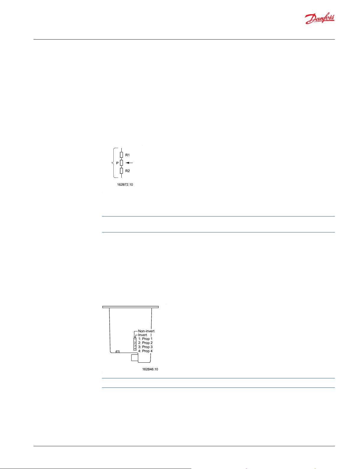
The proportional functions in the basic module are configured like this:
The value of P is 5 KΩ, R1 and R2 are 1.125 KΩ (See technical data for tolerances).
This configuration ensures that the output signal will be at least 25%-75% of the supply voltage.
Because of the output impedance of the sensors, it is recommended to use an amplifier if the application
draws more than 15 µA.
Standard
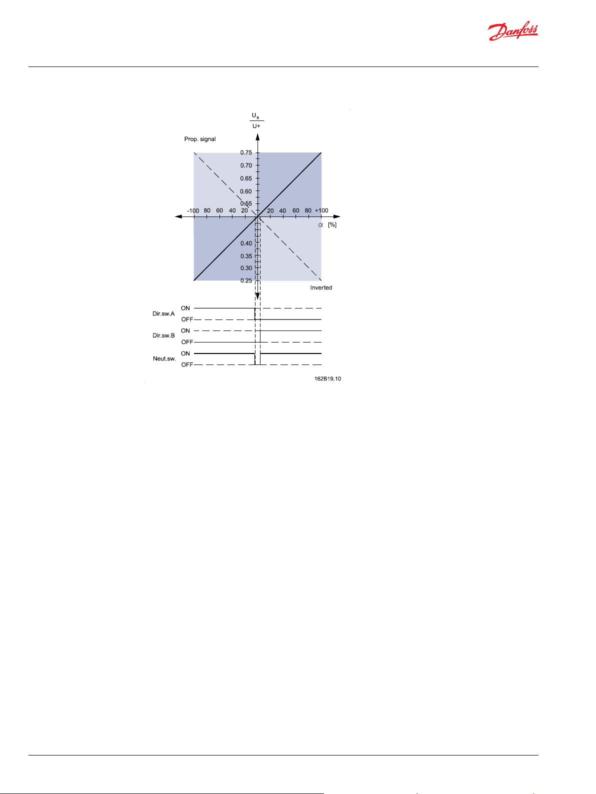
The Standard level electronic module provides amplifiers, inverting and signal relays on all proportional
outputs, and an electronic switch on all On/Off outputs.
The signal relays are controlled by the power supply in such a way that a power failure will disconnect the
output. (This will automatically send a Danfoss proportional valve to neutral position)
When used together with a Danfoss proportional valve signal inversion causes the joystick to move the
spool in the direction opposite to the default. This is equivalent to swapping the hoses on the valve
outlets.
The directional switches are not affected by the signal inversion.
©
Danfoss | December 2020 BC152886484305en-000302 | 11
Page 12
Technical Information
Prof 1, PVRE and PVRET Joystick
Prof 1
Factory setting: Non-inverted
Extended
The Extended level electronic module has the same configuration as the Standard level module.
Additionally it has adjustable proportional functions. The Extended level module offers the option of
individual signal adaptation (flow adjustment) and common dead-band compensation.
12 | © Danfoss | December 2020 BC152886484305en-000302
Page 13

Technical Information
Prof 1, PVRE and PVRET Joystick
Prof 1
The dead band compensation (D.B.c.) ensures that the dead band of the valve is reduced to a minimum
movement of the grip.
The dead band compensation is only active outside the neutral range, which ensures normal
amplification within the neutral position range.
The dead band compensation is set for all four proportional functions on one potentiometer.
For each proportional function there are two integrated potentiometers that independently control the
gain for the A and B directions of the signal output without limiting the movement range of the handle
(adjustable flow range).
The gain of each function can be adjusted from 0.25 to 2.00. This has no effect within the D.B.c. range.
Location of potentiometers for adjusting D.B.c and gain:
Factory setting @ 12 V
Dead band compensation 0.42 V
Signal gain 0.86
©
Danfoss | December 2020 BC152886484305en-000302 | 13
Page 14

Technical Information
Prof 1, PVRE and PVRET Joystick
Prof 1
CAN-enabled
There is a CAN-enabled electronic module available for the Prof family of joysticks.
The module provides a standard CANOpen interface. For further information read
Danfoss Technote on CAN bus components and see our webpage:
http://www.Danfoss.com
14 | © Danfoss | December 2020 BC152886484305en-000302
Page 15

Technical Information
Prof 1, PVRE and PVRET Joystick
Prof 1
Basic version connections
Numbers in [ ] indicate pin number in sub-D connector
©
Danfoss | December 2020 BC152886484305en-000302 | 15
Page 16

Technical Information
Prof 1, PVRE and PVRET Joystick
Prof 1
Standard and extended versions connections
Numbers in [ ] indicate pin number in sub-D connector.
16 | © Danfoss | December 2020 BC152886484305en-000302
Page 17

Technical Information
Prof 1, PVRE and PVRET Joystick
Prof 1
Technical Data
All
Enclosure Below flange IP 21
Above flange IP 50
Ambient temperature –30 - +60° [–22 - +140°F]
Max. force on handle 1000 N static
Basic
Supply voltages U+ ≤30 V
Proportional functions P 5 KΩ ±50%
R1 & R2 P × 0.225 ±1%
Max signal current 15 µA (1 mA peak)
Max direction switch load for all proportional functions 30 VDC / 2mA
Max push button load 30 VDC / 50mA
There are no electronics built in to the Basic level module.
Standard and Extended
Supply voltages UDC, U
Current consumption ≈150 mA
Signal voltage Us U
Signal load in neutral position Load type PVE Other
Signal current at max movement @ UDC = 12 V Us - 0.5 × U+ 6 kΩ
Signal current in neutral position @ UDC = 12 V ± 0 mA 0.4 mA
Inverter Non inverted Output signal = Us
Push buttons and directions switches for all proportional functions Max load 0.6 A
Push 7 & Push 8 Max load 30 VDC / 50 mA
Neutral position switch Max load 3 A
s
U
+
+
Max ripple 5%
Min → Max 0.25 → 0.75
Neutral position 0.50
Load impedance >6 kΩ >15 kΩ
@ UDC = 24 V ± 1.2 mA 0.4 → 1.2 mA
@ UDC = 24 V ± 0 mA 0.8 mA
Inverted Output signal =
10-30 V
± 0.6 mA
-1 × (Us – 0.5×U+) + 0.5×U
Us
15 kΩ
0.2 → 0.6 mA
+
©
Danfoss | December 2020 BC152886484305en-000302 | 17
Page 18

Technical Information
Prof 1, PVRE and PVRET Joystick
Prof 1
Extended only
Signal regulation Us U
Dead band compensation U
Prof1 dimensions
Min (50%) 0.37 → 0.63
s
U
U
Max (200%) 0.25 → 0.75
+
Min 0.00
s
Max 0.06
+
at 100% movement
at 50% movement
18 | © Danfoss | December 2020 BC152886484305en-000302
Page 19

Push/Dir.sw.4B
Push/Dir.sw.4A
Push/Dir.sw.3B
Push/Dir.sw.3A
PVEM
PVEH/A/S
DC
V310116.A
P4B
1
PVEO
3
2
1
3
1
2
3
1
2
2
3
S2UUS1
P3BP3A P4A
Prop 2
Function
Prop 1
E
U
-
+
U+
+
-
DC
Neut.sw.
U
+
+
U-U
U- (GND)
19
Pin no.78
6
3, 15, 16
1, 2, 14
10
21
20
22
F
NC
NC
Technical Information
Prof 1, PVRE and PVRET Joystick
Prof 1
Examples of Use
Signal leads must not also function as supply leads unless the distance between PVE and terminal board
is less than 3 m [120 in] and the lead cross-section is ≥ 0.75 mm2 [ AWG 18].
©
Danfoss | December 2020 BC152886484305en-000302 | 19
E : Emergency stop
: Signal leads
: Supply leads
Basic version used with controller
When using the Basic level module with a controller, it is recommend to use a filter similar to the one in
the figure below to ensure a symmetric and limited load on the proportional sensors.
Page 20

Technical Information
Prof 1, PVRE and PVRET Joystick
Prof 1
There are no electronics built in to the Basic level module
Standard program
The joystick variants offer a wide range of different combination possibilities. This may result in several
code numbers with identical functions (such as location of push button and choice of color).
Based on experience we have therefore put together a standard program.
The standard program of joysticks is available in the following variants:
4-way mechanical
•
Yellow push buttons with flat collar
•
Red color bands
•
Standard electronics (excluding basic and extended with flow and dead band compensation).
•
20 | © Danfoss | December 2020 BC152886484305en-000302
Page 21

Technical Information
Prof 1, PVRE and PVRET Joystick
Prof 1
Prop number ON/OFF
number
2 0 162F1116 162F1100
2 1 162F1117 162F1101
2 2 162F1118 162F1102
2 3 162F1119 162F1103
2 4 162F1120 162F1104
Code numbers Left hand Code numbers Right hand
2 5 162F1121 162F1105
2 6 162F1122 162F1106
3 0 162F1134 162F1132
3 1 162F1135 162F1133
3 2 162F1123 162F1107
3 3 162F1124 162F1108
3 4 162F1125 162F1109
©
Danfoss | December 2020 BC152886484305en-000302 | 21
Page 22

Technical Information
Prof 1, PVRE and PVRET Joystick
Prof 1
Prop number ON/OFF
number
3 2 162F1126 162F1110
3 3 162F1127 162F1111
3 4 162F1128 162F1112
4 0 162F1129 162F1113
4 1 162F1130 162F1114
4 2 162F1131 162F1115
Code numbers Left hand Code numbers Right hand
Selection Overview
22 | © Danfoss | December 2020 BC152886484305en-000302
Page 23

Technical Information
Prof 1, PVRE and PVRET Joystick
Prof 1
3. Top functions
Position 3A, 3B, 4A, 4B, 5, 6, 7 Position
3, 4
Code no. 162B…. Push button Proportional roller
Color Black 3000 3100
Red 3002 –
Yellow 3004 –
Grey 3008 –
1. Grip
Code no. 162B…. Description
Black Grey
1050 1000 Right hand Without On/Off push button in the side
1001 Right hand With On/Off push button in the side (Push 5)
1004 Right hand With dead mans button (Push 7)
1005 Right hand With On/Off push button in the side (Push 5) and dead mans button (Push 7)
1150 1100 Left hand Without On/Off push button in the side
1101 Left hand With On/Off push button in the side (Push 5)
1104 Left hand With dead mans button (Push 7)
1105 Left hand With On/Off push button in the side
(Push 5) and dead mans button (Push 7)
©
Danfoss | December 2020 BC152886484305en-000302 | 23
Page 24
kwa1385300991617
Technical Information
Prof 1, PVRE and PVRET Joystick
Prof 1
4. Color band
Code no. 162B…. Color
4002 Red
4003 Yellow
4000 Black
6. Cable
Code no. 162B…. Length [mm] Plug type Note
6013 4000 Leads Vertical
6014 4000 Leads Horizontal
6015 500 Clipper –
6016 230 TrimTrio –
6017 230 Tabs PVRE compatibility
24 | © Danfoss | December 2020 BC152886484305en-000302
Page 25

Technical Information
Prof 1, PVRE and PVRET Joystick
Prof 1
2. Front plates
5. Electronics
Code no. 162B…. Type Description
5000 Basic 2 - 4 proportional functions, 0 - 7 ON / OFF functions
5002 Standard 2 - 4 proportional functions with direction switch and neutral switch 0 - 7 ON / OFF functions
5004 Extended 2 - 4 proportional functions with direction switch and neutral switch Electronic flow adjustment
and dead band compensation on one or more prop functions 0 - 7 ON / OFF functions
5100 CAN enabled See CAN Tech-Note
©
Danfoss | December 2020 BC152886484305en-000302 | 25
Page 26

Technical Information
Prof 1, PVRE and PVRET Joystick
Prof 1
Standard program details
This table shows a breakdown of contents of the standard program joysticks.
Code numbers Front plate Grip code Electronic
162F1100 162B2000 162B1000 162B5002
12F1101 162B2010 162B1000 162B5002
12F1102 162B2020 162B1000 162B5002
162F1103 162B2030 162B1000 162B5002
162F1104 162B2004 162B1000 162B5002
162F1105 162B2005 162B1000 162B5002
162F1106 162B2005 162B1001 162B5002
162F1107 162B2102 162B1000 162B5002
162F1108 162B2103 162B1000 162B5002
162F1109 162B2103 162B1001 162B5002
162F1110 162B2127 162B1000 162B5002
162F1111 162B2127 162B1001 162B5002
162F1112 162B2137 162B1001 162B5002
162F1113 162B2200 162B1000 162B5002
162F1114 162B2200 162B1001 162B5002
162F1115 162B2210 162B1001 162B5002
162F1116 162B2000 162B1100 162B5002
162F1117 162B2001 162B1100 162B5002
162F1118 162B2002 162B1100 162B5002
162F1119 162B2003 162B1100 162B5002
162F1120 162B2004 162B1100 162B5002
162F1121 162B2005 162B1100 162B5002
162F1122 162B2005 162B1101 162B5002
162F1123 162B2120 162B1100 162B5002
162F1124 162B2130 162B1100 162B5002
162F1125 162B2130 162B1101 162B5002
162F1126 162B2127 162B1100 162B5002
162F1127 162B2127 162B1101 162B5002
162F1128 162B2137 162B1101 162B5002
162F1129 162B2200 162B1100 162B5002
162F1130 162B2200 162B1101 162B5002
162F1131 162B2210 162B1101 162B5002
162F1132 162B2100 162B1000 162B5002
162F1133 162B2112 162B1000 162B5002
162F1134 162B2107 162B1100 162B5002
162F1135 162B2121 162B1100 162B5002
26 | © Danfoss | December 2020 BC152886484305en-000302
Page 27
Technical Information
Prof 1, PVRE and PVRET Joystick
Prof 1
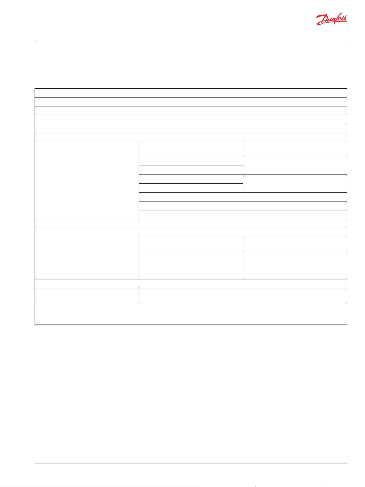
Prof 1 Joystick Specification
Prof 1 Joystick Specification - Customer specification
Code no:
Customer:
Application:
Subsidiary/Dealer:
1. Grip
2. Front plate
3. Top functions Position
(push button color)
3A: 3:
3B:
4A: 4:
4B:
5:
6:
1)
7:
4. Colour band
5. Main function module Set-up
2)
Inverted
(check mark = Inverted)
Prop. 1
Prop. 2
Prop. 3
Prop. 4
6. Cable
Compiled by:
Date:
1)
Only for deadman button
2)
Only for standard and extended level options. Factory setting is ”non-inverted” if nothing else is mentioned
3)
Only for extended level option. Factory setting is ”on” if nothing else is mentioned.
Checked by:
Date:
Position
(roller)
Flow reduction and dead-band compensation
(check mark = ON)
Prop. 1
Prop. 2
Prop. 3
Prop. 4
3)
©
Danfoss | December 2020 BC152886484305en-000302 | 27
Page 28

Technical Information
Prof 1, PVRE and PVRET Joystick
PVRE series 2
The PVRE series 2 is the successor to the popular PVRE joystick. This joystick builds on the known
technology from the Prof family of joysticks as well as the well known handles from the PVRE series 1
joysticks.
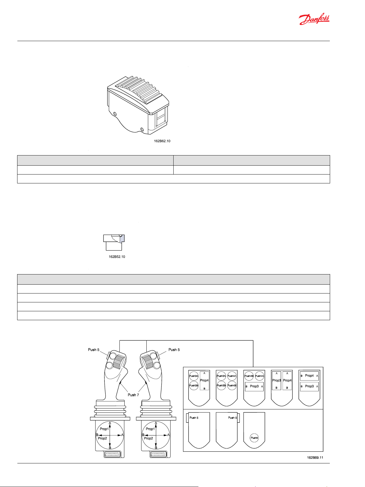
Versions
The PVRE handle is available in three different variants: No top function, with prop 3, and with two On/Off
functions (rocker switches).
Code no.
162F….
Symbol
Prop1 X X X X X
Prop 2 X X – – X
Prop 3 – – – – X
On/Off X – X – –
( ) Incl. PVRE series 1 adapter ring for mounting in place of a PVRE Series 1
1310
(1300)
1311
(1301)
1312
(1302)
1313
(1303)
1314
(1304)
28 | © Danfoss | December 2020 BC152886484305en-000302
Page 29

Technical Information
Prof 1, PVRE and PVRET Joystick
PVRE series 2
Location and Orientation of Functions
It is possible to turn the PVRE handle through 180° to make the direction of movement fit the application.
©
Danfoss | December 2020 BC152886484305en-000302 | 29
Page 30

13 1
25 14
P200181
Technical Information
Prof 1, PVRE and PVRET Joystick
PVRE series 2
Connections
PVRE/T version connections
Numbers in [ ] indicate pin number in sub-D connector.
Technical Data
Enclosure Below flange IP 21
Above flange IP 65
With On/Off IP 42
With Prop 3 IP 65
Ambient temperature –30 - +60° [–22 - +140°F]
Supply voltages U
Current consumption ≈150 mA
Signal voltage U
s
U
DC
DC
Max ripple 5%
Min → Max 0.25 → 0.75
Neutral position 0.50
10-30 V
30 | © Danfoss | December 2020 BC152886484305en-000302
Page 31

Technical Information
Prof 1, PVRE and PVRET Joystick
PVRE series 2
Signal load in neutral position Load type PVE Other
Load impedance >6 kΩ >15 kΩ
Signal current at max movement Us - 0.5 × U
6 kΩ
@ UDC = 12 V ±0.6 mA 0.2 → 0.6 mA
@ UDC = 24 V ±1.2 mA 0.4 → 1.2 mA
Signal current in neutral position @ UDC = 12 V ±0 mA 0.4 mA
@ UDC = 24 V ±0 mA 0.8 mA
On/Off switch Max load 0.6 A
Neutral position switch Max load 3 A
DC
U
s
15 kΩ
©
Danfoss | December 2020 BC152886484305en-000302 | 31
Page 32
P200182
Technical Information
Prof 1, PVRE and PVRET Joystick
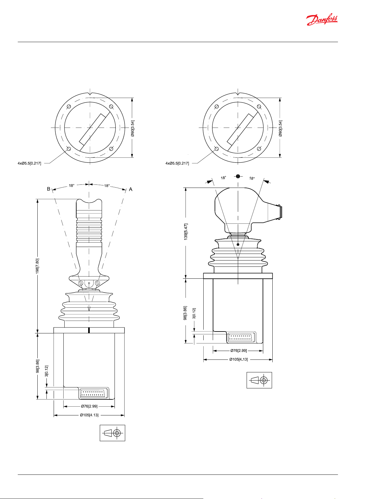
PVRE series 2
Dimensions
Dimension of PVRE and PVRET versions
32 | © Danfoss | December 2020 BC152886484305en-000302
Page 33

Push/Dir.sw.4B
Push/Dir.sw.4A
Push/Dir.sw.3B
Push/Dir.sw.3A
PVEM
PVEH/A/S
DC
V310116.A
P4B
1
PVEO
3
2
1
3
1
2
3
1
2
2
3
S2UUS1
P3BP3A P4A
Prop 2
Function
Prop 1
E
U
-
+
U+
+
-
DC
Neut.sw.
U
+
+
U-U
U- (GND)
19
Pin no.78
6
3, 15, 16
1, 2, 14
10
21
20
22
F
NC
NC
Technical Information
Prof 1, PVRE and PVRET Joystick
PVRE series 2
Examples of Use
©
Danfoss | December 2020 BC152886484305en-000302 | 33
: Emergency stop
: Signal leads
: Supply leads
PVRET Series 2
Page 34

Technical Information
Prof 1, PVRE and PVRET Joystick
PVRE series 2
34 | © Danfoss | December 2020 BC152886484305en-000302
Page 35

+
-
+
-
+
-
Prop 1
Prop 2
Prop 3
Push 7
Power Feedback
Push 8
To ADC
{15} White/Yellow [12]
{2} Brown [2]
{1} White [22]
{10} Violet [6]
{11} Grey/Pink [7]
{12} Red/Blue [8]
{24} White/Red [9]
{25} Brown/Red [10]
CAN Shield
CAN HI
CAN LO
Neutral Position Switch
{30} Green [11]
VBatt
GND
{3} Yellow/Grey [3]
{4} Pink/Green [4]
{5} Grey [5]
kwa1454709100064
Technical Information
Prof 1, PVRE and PVRET Joystick
PVRE series 2
PVRE
Numbers in {} indicate Samtec pin number, numbers in [] indicate DTM pin number
©
Danfoss | December 2020 BC152886484305en-000302 | 35
Page 36

Technical Information
Prof 1, PVRE and PVRET Joystick
PVRET series 2
The PVRET series 2 is the successor to the popular PVRET joystick. This joystick builds on the known
technology from the Prof family of joystick as well as the traditional handles from the PVRET series 1.
Version
Code no. 162F…. 1315
(1305)
Symbol
( ) Incl. PVRE series 1 adapter ring
PVRET version connections
Technical Data
Enclosure Below flange IP 21
Above flange IP 54
Ambient temperature –30 - +60° [–22 - +140°F]
Supply voltages U
Current consumption ≈150 mA
Signal voltage U
Signal load in neutral position Load type PVE Other
Signal current at max movement Us - 0.5 × U
Signal current in neutral position @ UDC = 12 V ±0 mA 0.4 mA
On/Off switch Max load 0.6 A
Neutral position switch Max load 3 A
s
U
DC
DC
Max ripple 5%
Min → Max 0.25 → 0.75
Neutral position 0.50
Load impedance >6 kΩ >15 kΩ
@ UDC = 12 V ±0.6 mA 0.2 → 0.6 mA
@ UDC = 24 V ±1.2 mA 0.4 → 1.2 mA
@ UDC = 24 V ±0 mA 0.8 mA
10-30 V
6 kΩ
DC
U
s
15 kΩ
36 | © Danfoss | December 2020 BC152886484305en-000302
Page 37

Technical Information
Prof 1, PVRE and PVRET Joystick
PVRET series 2
PVRET version dimensions
Dimensions illustration here
Examples of Use
: Emergency stop
: Signal leads
: Supply leads
©
Danfoss | December 2020 BC152886484305en-000302 | 37
Page 38

Danfoss
Power Solutions GmbH & Co. OHG
Krokamp 35
D-24539 Neumünster, Germany
Phone: +49 4321 871 0
Danfoss
Power Solutions ApS
Nordborgvej 81
DK-6430 Nordborg, Denmark
Phone: +45 7488 2222
Danfoss
Power Solutions (US) Company
2800 East 13th Street
Ames, IA 50010, USA
Phone: +1 515 239 6000
Danfoss
Power Solutions Trading
(Shanghai) Co., Ltd.
Building #22, No. 1000 Jin Hai Rd
Jin Qiao, Pudong New District
Shanghai, China 201206
Phone: +86 21 2080 6201
Products we offer:
Hydro-Gear
www.hydro-gear.com
Daikin-Sauer-Danfoss
www.daikin-sauer-danfoss.com
Cartridge valves
•
DCV directional control
•
valves
Electric converters
•
Electric machines
•
Electric motors
•
Gear motors
•
Gear pumps
•
Hydraulic integrated
•
circuits (HICs)
Hydrostatic motors
•
Hydrostatic pumps
•
Orbital motors
•
PLUS+1® controllers
•
PLUS+1® displays
•
PLUS+1® joysticks and
•
pedals
PLUS+1® operator
•
interfaces
PLUS+1® sensors
•
PLUS+1® software
•
PLUS+1® software services,
•
support and training
Position controls and
•
sensors
PVG proportional valves
•
Steering components and
•
systems
Telematics
•
Danfoss Power Solutions is a global manufacturer and supplier of high-quality hydraulic and
electric components. We specialize in providing state-of-the-art technology and solutions
that excel in the harsh operating conditions of the mobile off-highway market as well as the
marine sector. Building on our extensive applications expertise, we work closely with you to
ensure exceptional performance for a broad range of applications. We help you and other
customers around the world speed up system development, reduce costs and bring vehicles
and vessels to market faster.
Danfoss Power Solutions – your strongest partner in mobile hydraulics and mobile
electrification.
Go to www.danfoss.com for further product information.
We offer you expert worldwide support for ensuring the best possible solutions for
outstanding performance. And with an extensive network of Global Service Partners, we also
provide you with comprehensive global service for all of our components.
Local address:
Danfoss can accept no responsibility for possible errors in catalogues, brochures and other printed material. Danfoss reserves the right to alter its products without notice. This also applies to products
already on order provided that such alterations can be made without subsequent changes being necessary in specifications already agreed.
All trademarks in this material are property of the respective companies. Danfoss and the Danfoss logotype are trademarks of Danfoss A/S. All rights reserved.
©
Danfoss | December 2020 BC152886484305en-000302
 Loading...