

Page 1
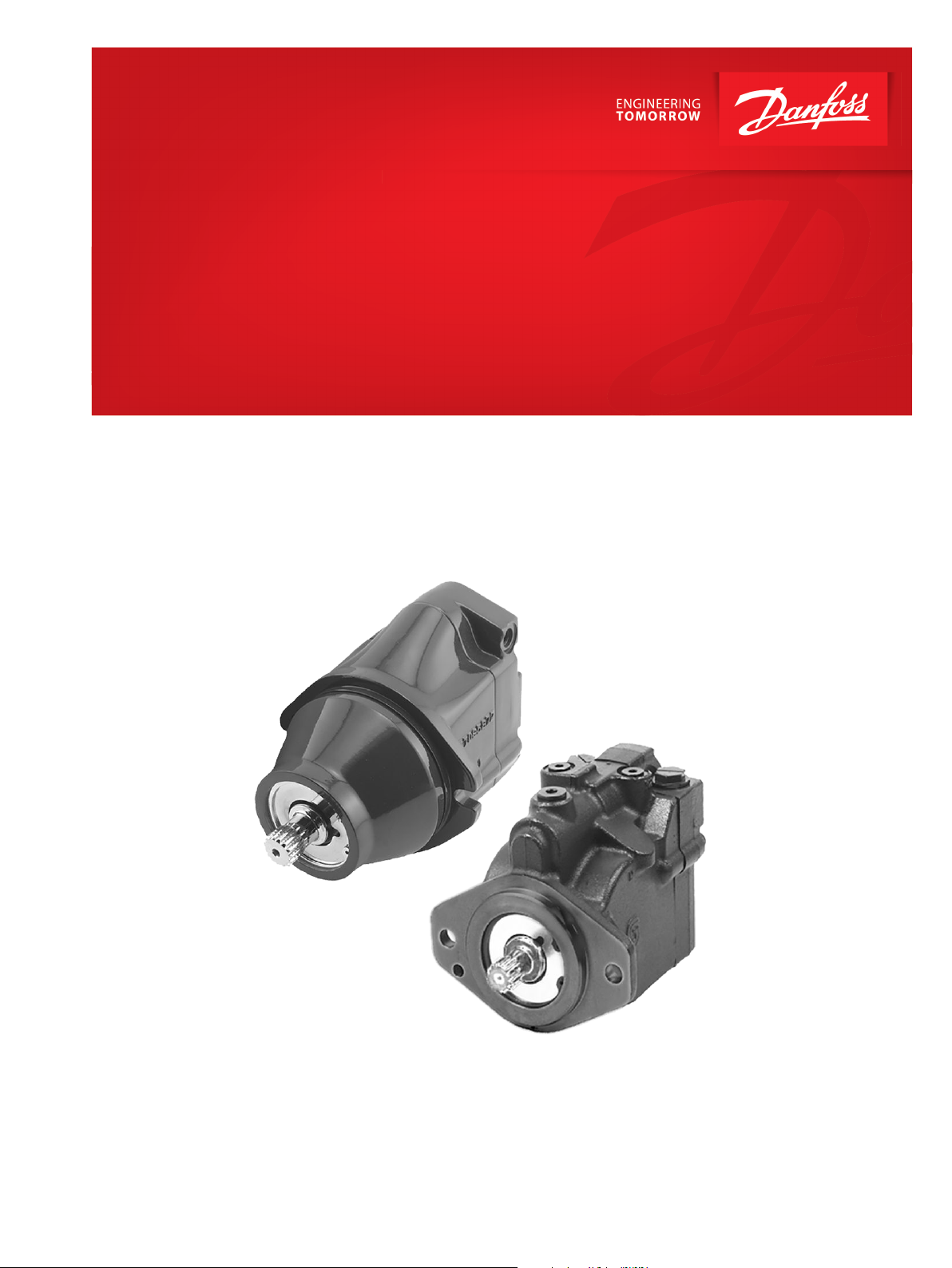
Functional Safety
Product Reliability Data (MTTF)
LC/KC Motor
powersolutions.danfoss.com
Page 2

Functional Safety
LC/KC Motor Reliability Data (MTTF)
Revision history Table of revisions
Date Changed Rev
November 2017 First edition 0101
2 | © Danfoss | November 2017 AB00000082en-US0101
Page 3

Functional Safety
LC/KC Motor Reliability Data (MTTF)
Contents
Introduction
Overview..............................................................................................................................................................................................4
Danfoss Component
LC Motor (30cc), and KC Motor (38cc).......................................................................................................................................5
Intended Use......................................................................................................................................................................................5
Results...................................................................................................................................................................................................5
Standards and Assumptions
Calculations........................................................................................................................................................................................ 6
MTTF for Individual Motor Function..........................................................................................................................................6
Component Information
F1: Safe Controllability (Motor at Demanded Displacement).......................................................................................... 7
References
List of References..............................................................................................................................................................................8
©
Danfoss | November 2017 AB00000082en-US0101 | 3
Page 4

Functional Safety
LC/KC Motor Reliability Data (MTTF)
Introduction
This technical report states the MTTF for a 30cc LC & 38cc KC motor configuration.
Overview
This MTTF data has been compiled by the engineering team responsible for the LC/KC Motor. These are
professionals at Danfoss, who have the authority and technical knowledge to calculate the MTTF Data for
this product based on the standards set in place by both the industry and/or Danfoss.
The purpose of this document is to assist in the transfer of MTTF information for the given product from
Danfoss to the appropriate party in a way which will result in a clear understanding and documentation
on how we derived it. This MTTF information is provided to assist in calculating the overall MTTF of a
complete or partially complete piece of machinery.
Danfoss cannot be held responsible for the suitability of these calculated MTTF values for use in the
calculation of the overall machinery MTTF values. The MTTF values for the LC/KC Motor are based on a
specific machine use, operating environment, and/or duty cycle as stated by the standards set in place by
both the industry and/or Danfoss. This communication along with any attached Danfoss drawings,
sketches, or data is transmitted in confidence.
No information stated in this document or any attachments or supplements may be reproduced or
disclosed in whole or in part without written permission of Danfoss. Further, neither these documents
nor any attachments are a warranty of any sort by Danfoss or a guarantee of machine suitability for its
intended purpose. It remains the responsibility of the machine manufacturer to ensure overall machine
functionality and overall machine safety.
We recommend consulting the functional safety cross BA team before applying the document to the
customer.
4 | © Danfoss | November 2017 AB00000082en-US0101
Page 5

Functional Safety
LC/KC Motor Reliability Data (MTTF)
Danfoss Component
LC Motor (30cc), and KC Motor (38cc)
The LC/KC family of closed circuit 2 position motors is designed for use with existing Danfoss hydraulic
pumps for the control and transfer of hydraulic power. LC/KC motors are compact and have high power
density where all units utilize a servo piston assembly that controls the displacement and resulting shaft
speed ranges.
LC/KC motors can be used together in combination with other Danfoss pumps and motors in the overall
hydraulic system. Danfoss hydrostatic products are designed with many different displacement, pressure,
and load-life capabilities. Go to the Danfoss Power Solutions website or applicable product catalog to
choose the components that are right for your complete closed circuit hydraulic system.
Intended Use
The LC/KC Frame variable motors are light to medium power two-position axial piston motors
incorporating an integral servo piston. They are designed for operation in closed and open circuit
applications. The LC/KC Frame motors consist of five unique rotating groups (displacements) and two
housing (mounting) configurations. Maximum speeds and maximum applied pressures for each
displacement vary.
The LC/KC standard control is a direct acting single line hydraulic control. This MTTF document applies
only to motors using this direct acting single line hydraulic control. The motor is spring biased to
maximum displacement and hydraulically shifted to minimum displacement. Minimum and maximum
displacement can be set with fixed internal stops. The large diameter servo piston allows smooth
acceleration and deceleration with relatively large circuit orificing.
Details regarding intended use, such as application examples and operating conditions, are available in
Technical Information documents on our Danfoss page
http://powersolutions.danfoss.com/literature/
For any intended use other than the above you are invited to contact your local Danfoss representative
for advice.
Results
The following table shows the MTTF values of motor configurations and special functions.
Results of MTTF on motor level
ID Motor Configuration MTTF [years]
F1 Motor with direct acting single line
©
Danfoss | November 2017 AB00000082en-US0101 | 5
hydraulic control
>150
Page 6

Functional Safety
LC/KC Motor Reliability Data (MTTF)
Standards and Assumptions
Calculations
The calculations are performed with reference to the Danfoss Global Standard GS-0078. The standard
GS-0078 defines the following options for how to determine the MTTF/MTTFd value for a specific
component or product. The process/algorithm selected will depend on:
•
Whether the component is purchased or manufactured
•
The availability of Danfoss field usage history
•
The availability of industry standard field usage history (primarily for electronic components)
•
Similarity of design to existing products
•
Knowledge of the design process
Some calculation options are listed below:
•
The methods outlined in ISO 13849-1 2006 Annexes C and D
•
Comparison to similar products already in production
•
Industry MTTF databases for widely available components (i.e. electronics)
MIL-HDBK-217
‒
Siemens SN29500
‒
Manufacturer’s Information
‒
•
MTBF data from Verification testing in PDLP
•
Danfoss design practices and procedures for hardware and software design
•
Defects data from Danfoss CQAR database and/or customer data
•
Information on sold products originates from Danfoss SAP
•
Information on application profiles originates from Danfoss technical support knowledge
•
Safety function = Not certified safety functions (no CE)
The assumptions and raw date of the calculation are listed in an internal document 70321456 MTTF
Calculation for LC_KC Motors. This document is stored in EDMS.
MTTF for Individual Motor Function
The following table lists the MTTF for each individual motor function. Please refer to F1: Safe
Controllability (Motor at Demanded Displacement) for further understanding of functions and the MTTF
values.
ID Function Specification/performance Input Output MTTF
F1 Safe controllability
Customer is responsible for correct port selection due to input signal.
(motor at demanded
displacement)
See TI manual for specification/
performance of function and
boundaries shown in
Hydraulic
pressure signal
[years]
Motor speed > 150
6 | © Danfoss | November 2017 AB00000082en-US0101
Page 7

Functional Safety
LC/KC Motor Reliability Data (MTTF)
Component Information
F1: Safe Controllability (Motor at Demanded Displacement)
A pressure input signal to the servo piston (X1 connection) will lead to a certain displacement of the
motor and based on the system flow through the motor a certain output speed at the motor shaft (e.g.,
vehicle speed) results out of that. The following table describes the failures and failed parts that can lead
to a failure of the function.
Detailed boundaries to ensure safe controllability:
•
Control: Shifting from maximum to minimum displacement occurs with a pressure signal of 14 to 69
bar
•
Control: Shifting from minimum to maximum displacement occurs with a pressure signal of less than
14 bar
It is the customer's responsibility to consider how to deal with a loss of SAFE CONTROLLABILITY during
analysis of the functional safety concept for the complete system.
Listed below are potential causes for failures:
Failure Failed Part Description
Motor not at demanded
displacement
Servo piston Motor output speed cannot be
Servo piston rings
Bias spring
Servo piston to swashplate
connection
Swashplate
Swashplate journal bearings
controlled as demanded
©
Danfoss | November 2017 AB00000082en-US0101 | 7
Page 8

Functional Safety
LC/KC Motor Reliability Data (MTTF)
References
List of References
ISO 13849-1,2 Safety of machinery – Safety-related parts of control systems
GS-0078 MTTF calculations for Danfoss products
CAR Customer Action Report. Danfoss global tool based process for managing defects on
520L0627 L and K Frame Variable Motors Technical Information Manual
L&K Frame Website http://products.danfoss.com/productdetail/powersolutions/piston-pumps-motors/closed-
Danfoss hydrostatics products
circuit-axial-piston-motors/l-k-motor-k/#/
8 | © Danfoss | November 2017 AB00000082en-US0101
Page 9

Functional Safety
LC/KC Motor Reliability Data (MTTF)
©
Danfoss | November 2017 AB00000082en-US0101 | 9
Page 10

Functional Safety
LC/KC Motor Reliability Data (MTTF)
10 | © Danfoss | November 2017 AB00000082en-US0101
Page 11

Functional Safety
LC/KC Motor Reliability Data (MTTF)
©
Danfoss | November 2017 AB00000082en-US0101 | 11
Page 12

Danfoss
Power Solutions GmbH & Co. OHG
Krokamp 35
D-24539 Neumünster, Germany
Phone: +49 4321 871 0
Danfoss
Power Solutions ApS
Nordborgvej 81
DK-6430 Nordborg, Denmark
Phone: +45 7488 2222
Danfoss
Power Solutions (US) Company
2800 East 13th Street
Ames, IA 50010, USA
Phone: +1 515 239 6000
Danfoss
Power Solutions Trading
(Shanghai) Co., Ltd.
Building #22, No. 1000 Jin Hai Rd
Jin Qiao, Pudong New District
Shanghai, China 201206
Phone: +86 21 3418 5200
Products we offer:
Comatrol
www.comatrol.com
Turolla
www.turollaocg.com
Hydro-Gear
www.hydro-gear.com
Daikin-Sauer-Danfoss
www.daikin-sauer-danfoss.com
Bent Axis Motors
•
Closed Circuit Axial Piston
•
Pumps and Motors
Displays
•
Electrohydraulic Power
•
Steering
Electrohydraulics
•
Hydraulic Power Steering
•
Integrated Systems
•
Joysticks and Control
•
Handles
Microcontrollers and
•
Software
Open Circuit Axial Piston
•
Pumps
Orbital Motors
•
PLUS+1® GUIDE
•
Proportional Valves
•
Sensors
•
Steering
•
Transit Mixer Drives
•
Danfoss Power Solutions is a global manufacturer and supplier of high-quality hydraulic and
electronic components. We specialize in providing state-of-the-art technology and solutions
that excel in the harsh operating conditions of the mobile off-highway market. Building on
our extensive applications expertise, we work closely with our customers to ensure
exceptional performance for a broad range of off-highway vehicles.
We help OEMs around the world speed up system development, reduce costs and bring
vehicles to market faster.
Danfoss – Your Strongest Partner in Mobile Hydraulics.
Go to www.powersolutions.danfoss.com for further product information.
Wherever off-highway vehicles are at work, so is Danfoss. We offer expert worldwide support
for our customers, ensuring the best possible solutions for outstanding performance. And
with an extensive network of Global Service Partners, we also provide comprehensive global
service for all of our components.
Please contact the Danfoss Power Solution representative nearest you.
Local address:
Danfoss can accept no responsibility for possible errors in catalogues, brochures and other printed material. Danfoss reserves the right to alter its products without notice. This also applies to products
already on order provided that such alterations can be made without changes being necessary in specifications already agreed.
All trademarks in this material are property of the respective companies. Danfoss and the Danfoss logotype are trademarks of Danfoss A/S. All rights reserved.
©
Danfoss | November 2017 AB00000082en-US0101
 Loading...