

Data sheet
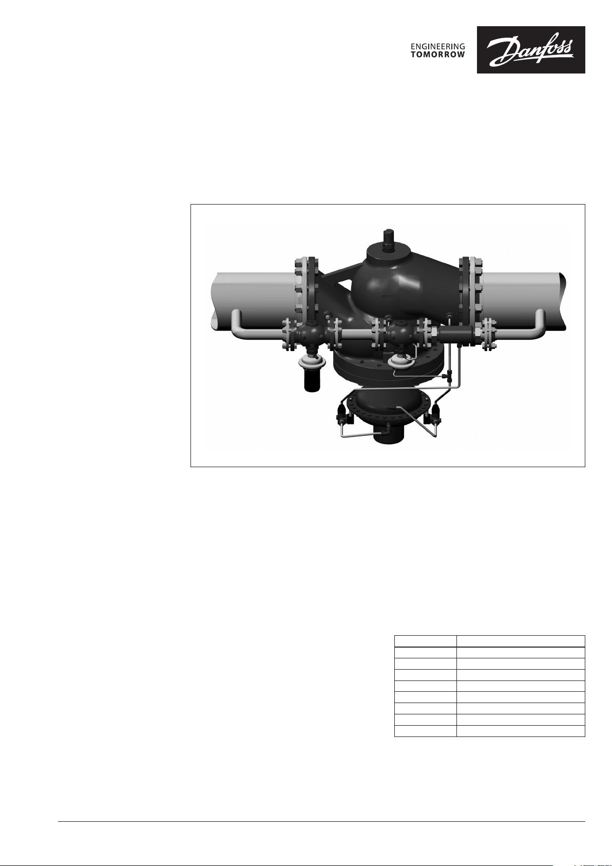
Pilot-controlled differential pressure and flow
controller (PN 16, 25, 40)
PCVPQ - flow and return mounting, adjustable setting
Description
Pilot-controlled flow and differential pressure
controller is a self-acting differential pressure
controller primarily for use in district heating,
district cooling or in industrial systems as well. It
can be flow and return mounted in applications
with and without heat exchanger like large
substations and distribution stations.
The control function of the PCVPQ controller
is defined by the control function of the pilot
controller. Setting of flow is done on main
controler , setting of differential pressure is done
on the pilot controller.
Throttle valve data can be found on page 8.
Main data1) :
• DN 50-250
• kVS 32-630 m3/h
• PN 16, 25, 40
2)
3)
• Temperature:
- Circulation water/glycolic water up to 30%:
2 … 150°C
• Connections:
- Pilot controller:
ext. thread (weld-on tailpieces) or flange
- Main valve: flange
1)
for details see Technica l data and Ordering sections
2)
smaller DN on re quest
3)
PN 40 on special re quest
Features:
- Differential pressure and flow controller
- Extremely high control ratio (see Tab.1) as a
result of low pilot controller min. flow rate
(kVS value) and high flow rate (kVS) of the main
valve
- Small overall dimensions comparing to
standard design (especially height)
- Higher valve capacities for DN 150-250
comparing to standard design
- High control stability
- Smooth operation flow controller
- Water/glycolic water applications
Tab. 1
DN Min. control rat io
50 100 : 1
65 140 : 1
80 220 : 1
100 300 : 1
125 400 : 1
150 400 : 1
200 550 : 1
250 750 : 1
© Danfoss | 2021.02 AI179486466874en-010303 | 1
Data sheet Pilot-controlled differential pressure and flow controller PCVPQ (PN 16, 25, 40)
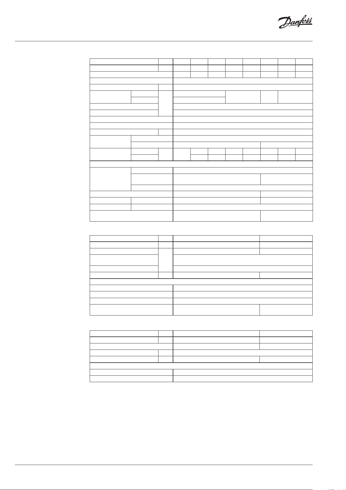
Technical Data Main valve
Nominal diameter DN 50 65 80 100 125 15 0 200 250
kVS value m3/h 32 50 80 125 160 320 450 630
Cavitation factor z 0.5 0.5 0.45 0.4 0.35 0.3 0.2 0.2
1)
Stainless steel M . No. 1.4571
2)
EPDM
Leakage acc. to standard IEC 534 ≤ 0.05% of k
Nominal pressure PN 16, 25, 40
Max. differential
pressure
Min. differential pressure 0.5
PN 16
PN 25/40 20
bar
16
Min. static pressure 1.5
Media Circulation water/glycolic water up to 30%
Media pH Min. 7, max. 10
Media temperature °C 2 … 150
Connections
Weight
Main controller Flange
Pilot controller Ext. thread (weld-on tailpieces) and flange Flange
PN 16
PN 25/40 31 34 63 72 147 264 347
kg 18.5
28.5 31 61 71 12 0 193 337
Materials
PN 16 Grey cast iron EN-GJL-250 (GG-25)
Valve body
PN 25
Ductile cast iron
EN-GJS-400-18-LT (GGG-40.3)
PN 40 Cast steel EN-GP-240-GH (GS- C 25) 2)
Valve seat Stainless steel M. No. 1.4021 Stainless steel M. No. 1.4313
Valve cone VFQ 21 Stainless steel M. No. 1.4404 Stainless steel M. No. 1.4021
Sealing VFQ 21 EPDM
Pressure relieve system Bellows
1)
VS
15 12 10
Cast steel EN-GP-240-GH
(GS-C 25)
Diaphragm2) (T
Bellows1) (T
max
150 °C )
max
300 °C)
1)
Defined by pilot controller
Main actuator
For main va lve DN 50 - 125 150 - 250
Actuator size cm
Max. operational pressure
Flow restrictor differential
pressure p
Diff. pressure setting ranges
1)
b
1)
Weight kg 11 24
Materials
Housing Stainless steel M. No. 1.0338
Control diaphragm EPDM
Impulse tube Stainless steel tube Ø10 × 0.8 mm
Number of throttle valves
(mounted on impulse tubes)
bar
2
250 630
25 16, 2 5
0.2/0.5
0.2-1.0 / 0.3-2.0 / 1-5 / 3-12
1 2
Trottling element
For main va lve DN 50 - 125 150 -250
Size of throttling element DN 25 40
Connections Welded end Flange
Max. operational pressure bar 25, 40
Weight kg 3.2 6.6
Materials
Body material Red bronze, M. No. 2.1090
Impulse tube Stainless steel tube Ø10 × 0.8 mm
2 | AI179486466874en-010303 © Danfoss | 2021.02
Data sheet Pilot-controlled differential pressure and flow controller PCVPQ (PN 16, 25, 40)
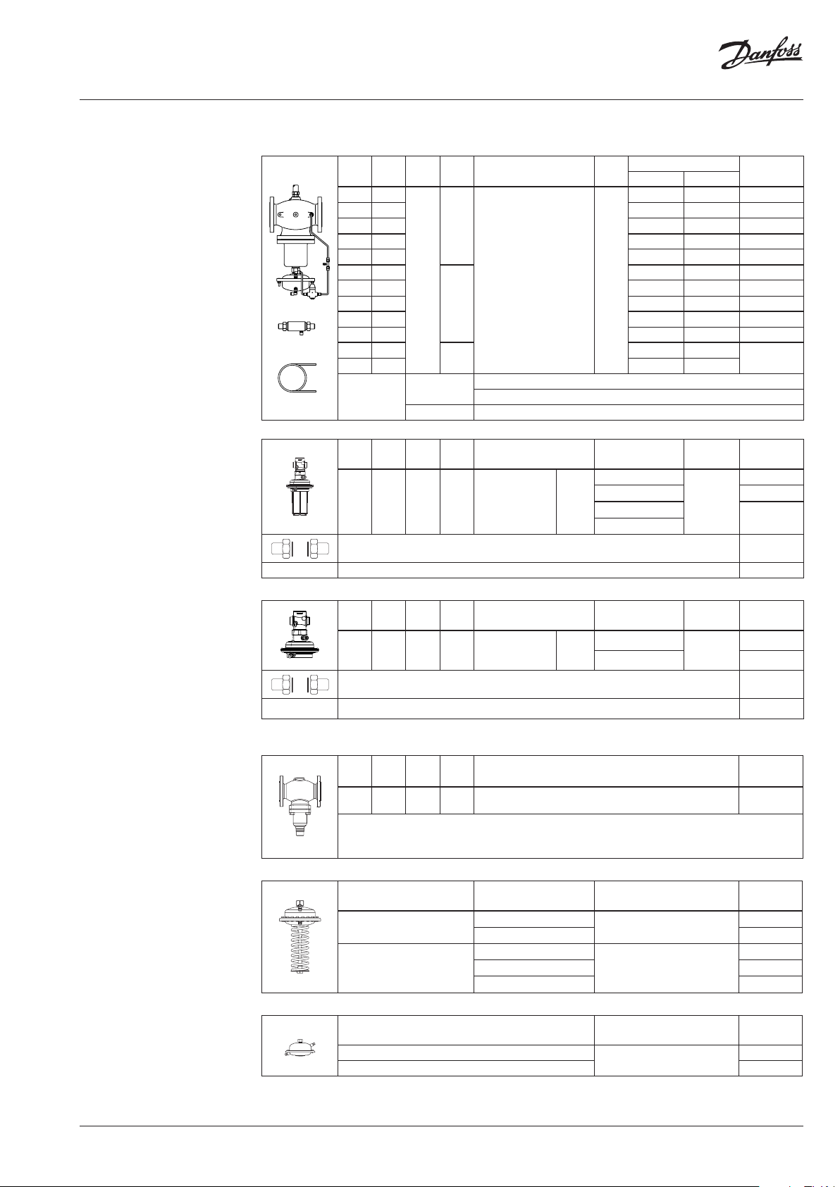
Ordering
Example 1:
Pilot-controlled flow and
differential pressure controller; flow
80 m3/h;
∆p 0.8 bar; PN 16; flow restrictor
Δpb 0.5 bar; T
- 1× PCV-VFQ 21 DN 100
Code No.: 00 3G1533
- 1× Pilot controller AVP DN 25
PN16 0.2 - 1.0 bar
Code No.: 00 3H6319
- 1× Pilot controller AVP-F 0. 5
Code No.: 00 3H6341
- 1× Mounting set for Impulse
tube Code No.: 0 03G159 9
max
150 °C
DN 50-125
PCV-VFQ 21 - Main controller, throttling element, throttle valve, impulse tubes
Flow range (m3/h)
max
∆pb 0.2 bar ∆pb 0.5 bar
0. 8-16 1.2-24 003G16 27
0. 8-16 1.2-24 003G 6710
6-63 9-90
DN 25
DN
k
(mm)
VS
(m3/h)
T
max
PN Connection
(°C)
Δp
(bar)
50 32
65 50 3-28 4-40 003G 6895
80 80 4-40 6-58 003G6898
16
100 125 6-63 9-90 00 3G1533
125 160 8-80 12-120 0 03G1534
50 32
65 50 3-28 4-40 003G 6878
80 80 4-40 6-58 0 03G157 8
150
Flange EN 1092-2 15
25
100 125 6-63 9-90 003G1543
125 160 8-80 12-120 0 03G154 4
100 125
125 160 8-80 12-120
Impulse tube
40
Copper
Stainless steel
Ø 6 × 1 × 3000 mm
Ø 10 × 1 × 1500 mm
Ø 10 × 0.8 × 1500 mm
AVP Pilot controller for differential pressure control - PN 25
DN
k
(mm)
VS
(m3/h)
T
max
PN Connection
(°C)
Δp setting range
(bar)
0. 2-1.0
25 8.0 150 25
Cylin dr.
ext. thread acc. to
ISO 228/1
G 1¼ A
0.3-2.0 003H6329
1-5
3-12
Weld-on tailpieces DN 25 003 H6910
Mounting set for impulse tube
2)
AVP- F Pilot controller for flow control - PN25
DN
k
T
VS
max
(mm)
(m3/h)
PN Connection
(°C)
Cylindr. ext.
25 8.0 150 25
thread acc. to
G 1¼ A
ISO 228/1
Weld-on tailpieces DN 25 003 H6910
Mounting set for impulse tube
2)
Δp
b
(bar)
0.2
0.5 003H6341
Δp
(bar)
Δp
(bar)
Code No.
1)
max
on request
Code No.
003 H6319
20
on request
003G1599
max
Code No.
20
003H6335
003G1599
Example 2:
Pilot-controlled flow and
differential pressure controller; flow
58 m3/h;
∆p 1 bar; PN 40; flow restrictor Δpb
0.2 bar; T
max
150 °C
- 1× PCV-VFQ 21 DN 100
Code No.: On request
- 2× Pilot controller
VFG 2 DN 25 PN40
Code No.: 06 5B2413
- 1× Pilot actuator AFP 0.15-1.5
Code No.: 003G1016
- 1× Pilot actuator AFPB- F 0.2
Code No.: 003G10 26
- 2× Mounting set for Impulse
tube Code No.: 0 03G1391
2)
Contains accessories fo r remounting
the impulse tub e on the pilot controller
from internal co nnection (factory
delivered) to e xternal connectio n.
3)
Actuator do es not have excess pressure
safety valve
VFG 2 Pilot controlers - PN40 (need to order 2 pcs)
DN
k
T
VS
max.
(mm)
25 8.0
(m3/h)
PN Connections Code No.
(°C)
150
40 Flanges acc. to EN 1092-1 065B 2413
(200)
AFP / AFP-9 Actuators for differential pressure control
Typ e
AFP-9
AFP
3)
∆p setting range
(bar)
1-6
0.5-3 0 03G1015
0.15 -1.5
0.1-0.7 00 3G1017
0.05-0.35 003 G1018
AFPB(-F) Actuators for flow control
∆p setting range
(bar)
0.2
0.5 003 G1027
for DN Code No.
15-125
00 3G1014
003 G1016
15-2 50
Max. operat. pressure Code No.
25
003 G1026
AI179486466874en-010303 | 3© Danfoss | 2021.02

Data sheet Pilot-controlled differential pressure and flow controller PCVPQ (PN 16, 25, 40)
Ordering (Continuous)
Example 3:
Pilot-controlled flow and
differential pressure controller; flow
260 m3/h; Δp 1.8 bar; PN 16; flow
restrictor Δpb 0.5 bar; T
- 1× PCV-VFQ 21 DN 100
Code No.: 003G1535
- 1× Pilot controller AVP DN 25
PN16 0.3 - 2.0 bar
Code No.: 003H6379
- 1× Pilot controller AVP-F 0. 5
Code No.: 003H6 391
- 1× Mounting set for Impulse
tube Code No.: 0 03G159 9
1)
Contains accessorie s for remounting
the impulse tub e on the pilot controller
from intter nal connection (factor y
delivered) to e xternal connectio n.
2)
Contains accessories fo r remounting
the impulse tub e on the pilot controller
from internal co nnection (factory
delivered) to e xternal connectio n.
max
150 °C
DN 150-250
PCV-VFQ 21 - Main controller, throttling element, throttle valves, impulse tubes
Flow range (m3/h)
∆pb 0.2 bar ∆pb 0.5 bar
15-14 5 25-220 12 0 03G1535
15-14 5 25-220 12 0 03G154 5
DN 40
DN
k
T
VS
max
(mm)
(m3/h)
PN Connection
(°C)
150 320
150
16
Flange EN 1092-2
25
200 450 20 -180 30-280
250 630 25-250 40-380 0 03G1537
150 320
200 450 20 -180 30-280
250 630 25-250 40-380 0 03G1547
Ø 6 × 1 × 3000 mm
Ø 10 × 1 × 1500 mm
Impulse tube
Copper
Stainless steel Ø 10 × 0.8 × 1500 mm
AVP Pilot controller for differential pressure control
DN
k
T
VS
max
(mm)
(m3/h)
PN Connection
(°C)
40 16 150 25 Flange EN 1092-2
Mounting set for Impulse tube
1)
Δp setting
range
(bar)
0. 2-1.0
0.3-2.0 003H6379
1-5
3-12
AVP- F Pilot controller for flow control
DN
k
T
VS
max
(mm)
(m3/h)
PN Connection
(°C)
40 16 150 25 Flange EN 1092-2
Mounting set for impulse tube
2)
Δp
b
(bar)
0.2
0.5 003H 6391
Δp
(bar)
Δp
(bar)
Δp
max
(bar)
max
Code No.
003G153 6
10
003G1546
10
Code No.
003H6373
16
on request
003G1599
max
16
Code No.
003H6385
003G1599
1)
Impulse tub es on T>150 °C or PN> PN 16
should be of stai nless steel
2)
Consist of a nipple , compression ring
and nut
Accessories
Type designation Description Connections Co de No.
Impulse tube set AF
Compression fitting
Throttle valve-PCV Regulating and shut-off device - 065Z1502
Service kits AVP(-F) flow
Type designation
Valve insert
Type designation
Actuator without adjustable handle (AVP-F)
Actuator with adjustable handle (AVP)
Service kits VFQ 21
Type designation For valve
- 1× Copper tube Ø10 × 1 × 1500 mm
1)
- 1 × compression fitting for imp.
tube connection to pipe (G ⁄)
- 003G1391
- 2 × socket
2)
For impulse tube Ø10 connections to
controller
DN
(mm)
G ⁄ 003G1468
k
DN
VS
(m3/h)
25 8.0
Δp setting range
(bar)
0.2
0.5
0. 2-1.0
0.3-2.0
k
VS
(m3/h)
Code No.
003H6875
Code No.
003H6839
003H6840
003H6834
003H6835
Code No.
Valve insert VFQ 2 40 20 065B2799
Stuffing cone (with EPDM O-rings) 003G1464
4 | AI179486466874en-010303 © Danfoss | 2021.02

Data sheet Pilot-controlled differential pressure and flow controller PCVPQ (PN 16, 25, 40)
Installation positions Both main and pilot controllers have to be
installed in horizontal pipes only, with a pressure
actuator oriented downwards.
Installation in return pipe
Main controller
Throttling
element
Pilot controllers
T
max
= 150 °C
Installation in flow pipe
Main controller
Throttling
element
Pilot controllers
Function Pressure changes from inlet pipe (+p) and from
throttling element (-p) are being transferred
through the impulse tubes to the main actuator
chambers and act on control diaphragm
In case of small flow rates the main controller is
closed and control is taken by the pilot controller
only. With increasing the flow rate, a negative
pressure is built in the throttling element.
This partial vacuum acts on the main actuator
diaphragm and causes the main controller to
open.
◯ p
−
Throttling
element
Throttle valve
Bypass
⊕ p
Main valve
Main controller
Main actuator
Pilot controller
AI179486466874en-010303 | 5© Danfoss | 2021.02

Data sheet Pilot-controlled differential pressure and flow controller PCVPQ (PN 16, 25, 40)
Pressure temperature
diagram
Working area is below P-T line
and it ends at Tmax for each
valve
PN 16
EN - GJL- 250
(GG -25)
PN 25
EN-GJS- 400
(GGG-40.3)
Dimensions
150
150
Maximum allowed operating pressure as a function of media temperature (according to EN 1092-2)
PN 40
EN-GP-240-GH
(GS- C 25)
150
Maximum allowed operating pressure as a function of media temperature (according to EN 1092-1)
Impulse tubes (pos. ①, ②, ③) are part of the
delivery. Their shape depends on the controller
type. In case of high temperatures
(T
> 150 °C) seal pots have to be installed. For
max
details see relevant Instructions.
T
150 °C DN 50-250
max
The components shown with dashed lines are
NOT part of the delivery. The pipes (pos. ④) must
be welded during mounting.
L
④
②
D
DN 50 65 80 100 125 150 200 250
L
H
1
H
2
D 263 263 263 263 263 380 380 380
230 290 310 350 400 480 600 730
390 425 425 530 530 619 6 47 697
mm
152 16 4 164 194 19 4 269 332 355
①
③
Impulse
tubes
①
②
③
T
max
200 °C 300 °C
Cu Ø 6 × 1
SS Ø 10 × 0.8
Cu Ø 10 × 1
SS Ø 10 × 0.8
2
H
1
H
6 | AI179486466874en-010303 © Danfoss | 2021.02

Data sheet Pilot-controlled differential pressure and flow controller PCVPQ (PN 16, 25, 40)
Dimensions (cont inuous)
T
150 °C DN 50-125
max
throttling element
pilot controller AVP-F
pilot controller AVP
Pipes Pos. ④:
DN 25: Pipes Ø 33.7 × 2.6
DN 40: Pipes 48.3 × 3.2
T
150 °C DN 150-250
max
④
④
DN 50 65 80 10 0 125
A
160
244
mm
290 290 290 290 290
B
1
D
75
159
ca . 120 0
75
159
A
A
Pipes Pos. ④:
DN 25: Pipes Ø 33.7 × 2.6
DN 40: Pipes 48.3 × 3.2
min 300
290
200
ca. 1200
DN 15 0 200 250
D
1
A 320 350 410
B 310 336 412
320 385 500
mm
200
min 300
AI179486466874en-010303 | 7© Danfoss | 2021.02

Data sheet Pilot-controlled differential pressure and flow controller PCVPQ (PN 16, 25, 40)
6
20
(1 revolution of spindle equals to 1 mm stroke)
Flow [l/min]
Throttle valve
Flow diagram
Throttle valve is regulating and shut-off device,
which is / are installed on the impulse tubes
connected to main PCV actuator. Number of
used throttle valves can be seen in table for Main
actuator in Technical Data section.
Function of throttle valve is to control flow
speed through impulse tube and consequently
influence on PCV’s reaction time. Influence
on reaction time is not completly defined and
strongly depends on application conditions
and could significantly vary from application to
application.
In general:
- by opening of the valve (clockwise) PCV’s
reaction time increases
- by valve closing (counterclockwise) PCV’s
reaction time decreases
In case valve is completly closed it has function
as shut-off valve.
Throttle valve is delivered from factory in
completly open position.
Main data:
• DN 4
• used for Ø10 mm impulse tube
5
4
3
2
1
0
0 2 4 6 8 10 12 14 16 18
Stroke [mm] = no. of revolution
© Danfoss | DHS-SRMT/SI | 2021.028 | AI179486466874en-010303
 Loading...