

Page 1
Instructions
Pilot-controlled PCVQ
DN 100 - DN 250
PN 16 / PN 25
Table of Contents
1 Safety Notes ...................................................... 2
2 Definition of Application ............................ 2
3 Description .......................................................... 3
3.1 Construction ......................................................... 3
3.2 Mode of Operation ........................................... 3
4 Technical Data .................................................. 4
5 Scope of Delivery ............................................. 4
6 Assembly ............................................................. 5
6.1 Prior to Assembly ............................................... 5
6.2 Installation Position,
Installation Place ................................................ 5
6.3 When Installaling observe .............................. 5
6.4 Impulse Tube Installation ................................ 5
6.5 Insulation .............................................................. 5
6.6 Installation Scheme ........................................... 6
6.7 Assembly Drawings, Dimensions ................ 7
7 Start-up ..................................................................9
7.1 Required static Pressure .................................. 9
7.2 Leak and Pressure Test ...................................... 9
7.3 Filling the System ............................................... 9
7.4 Start-up ................................................................... 9
7.5 Putting out of Operation ................................. 9
7.6 Flow Rate Adjustment ....................................... 9
7.7 Flow Adjusting Curves ................................... 11
7.8 Sealing ................................................................. 13
7.9 Adjustement of the Throttle Valves .......... 13
7.10 Function Test ..................................................... 13
8 Trouble Shooting ......................................... 14
9 Replacement of Valve,
Actuator, Trims .............................................. 15
9.1 Dismounting and
Mounting Actuator Valve ............................. 15
9.2 Replacement of Trim Valve VFQ 21 ........... 17
9.3 Dismounting,
Mounting Actuator AVP-F ............................ 18
9.4 Replacement of Trim Valve AVP-F .............. 18
© Danfoss | 2016.05
VI.JA.G3.02 | 1
Page 2
Instructions Pilot-controlled PCVQ DN 100 - DN 250 (PN 16, PN 25)
1 Safety Notes
2 Definition of
Application
Prior to assembly and
commissioning to avoid injury
of persons and damages of the
devices, it is absolutely
necessary to carefully read and
observe these instructions.
Necessary assembly, start-up, and maintenance
work must be performed only by qualified,
trained and authorized personnel.
Prior to assembly and maintenance work on the
controller, the system must be:
depressurized,
cooled down,
emptied and
cleaned.
Please comply with the instructions of the
system manufacturer or system operator.
The controller is used for flow rate limitation of
water for heating, district heating and cooling
systems.
The admissible medium temperatures depend
on the design and comprise 5 to 150 °C,
5 to 200 °C.
MAINTENANCE
FREE
The technical data on the rating plates determine
the use.
2 | © Danfoss | 2016.05
VI.JA.G3.02
Page 3
Instructions Pilot-controlled PCVQ DN 100 - DN 250 (PN 16, PN 25)
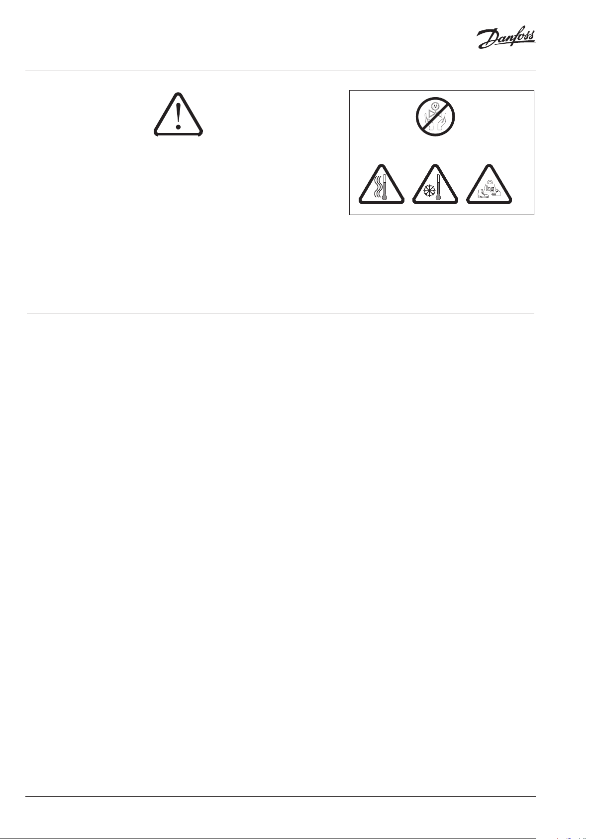
Pilot controller AVP-F
Adjusting throttle
T
only by DN150-250
3 Description
3.1 Construction
(Flow Rate)
hrottling valve
3.2 Mode of Operation
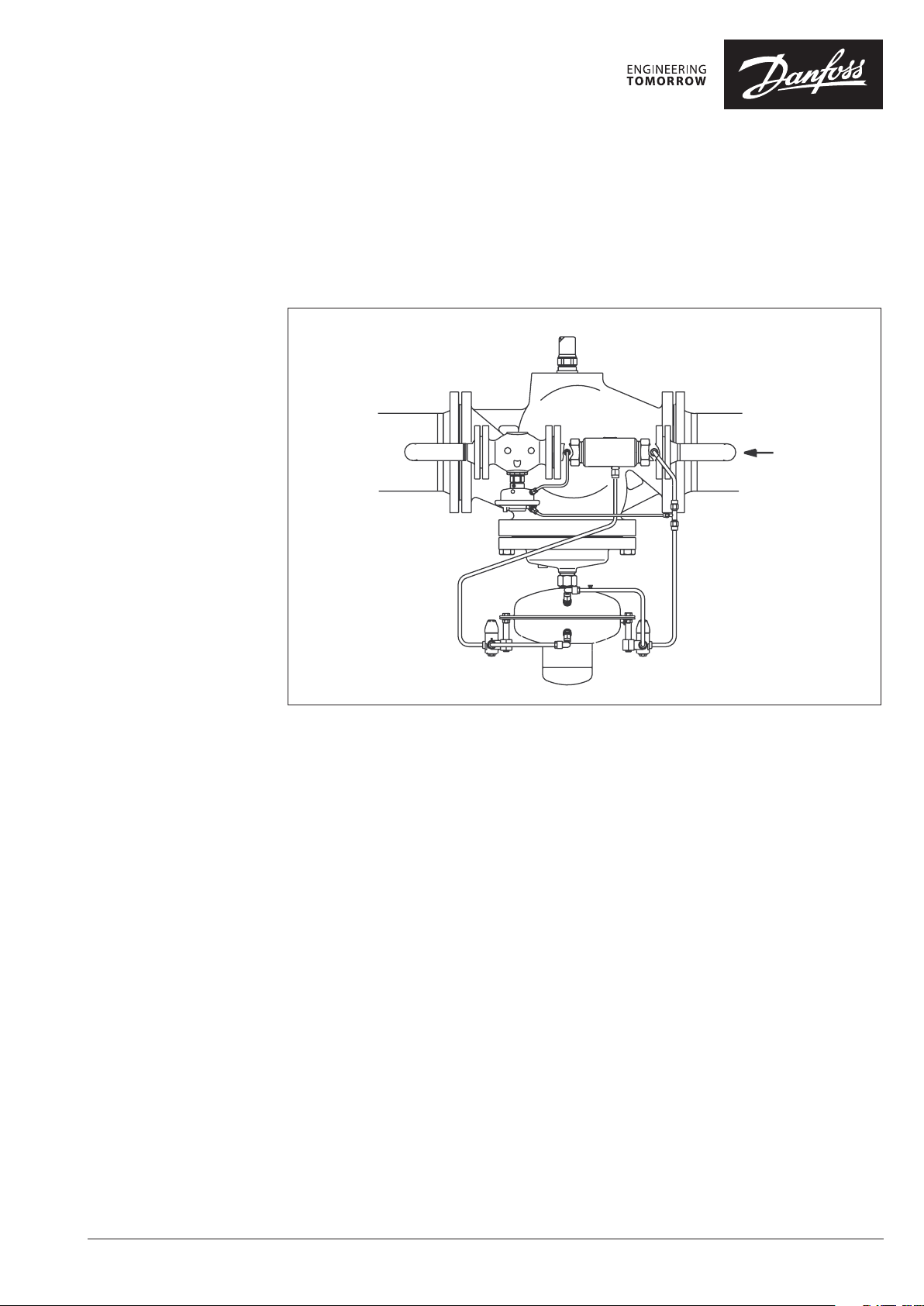
The control unit consists of the PCV-VFQ21
valve unit, installed in the main pipe and AVP-F
installed as pilot controllers in the bypass. In the
bypass line, a throttle element is installed in front
of the pilot controller.
The controller keeps the differential pressure
across the main valve flow restrictor on a
constant level and restricts the flow rate to the
adjusted setpoints.
The valve and the pilot valves are pressurebalanced.
The setpoint for the flow rate limitation is
adjusted at the adjusting throttle of the valve
unit.
The valve unit in the main pipe is opening on
rising pressure. The pilot controller in the bypass
line is closing on rising pressure.
Throttling element DE
Valve unit PCV-VFQ 21
Throttling valve
Flow Rate Limitation
If the flow rate reaches the adjusted setpoint, the
differential pressure increases at the adjusting
throttle. This differential pressure acts on the
actuator AVP-F via the impulse tubes and the
valve AVP-F closes. Consequently, the valve of
the valve unit is throttled, too, and the flow rate
is restricted.
4 Technical Data Technical data, see rating plates and the PCV
VI.JA.G3.02
data sheet.
© Danfoss | 2016.05 | 3
Page 4
Instructions Pilot-controlled PCVQ DN 100 - DN 250 (PN 16, PN 25)
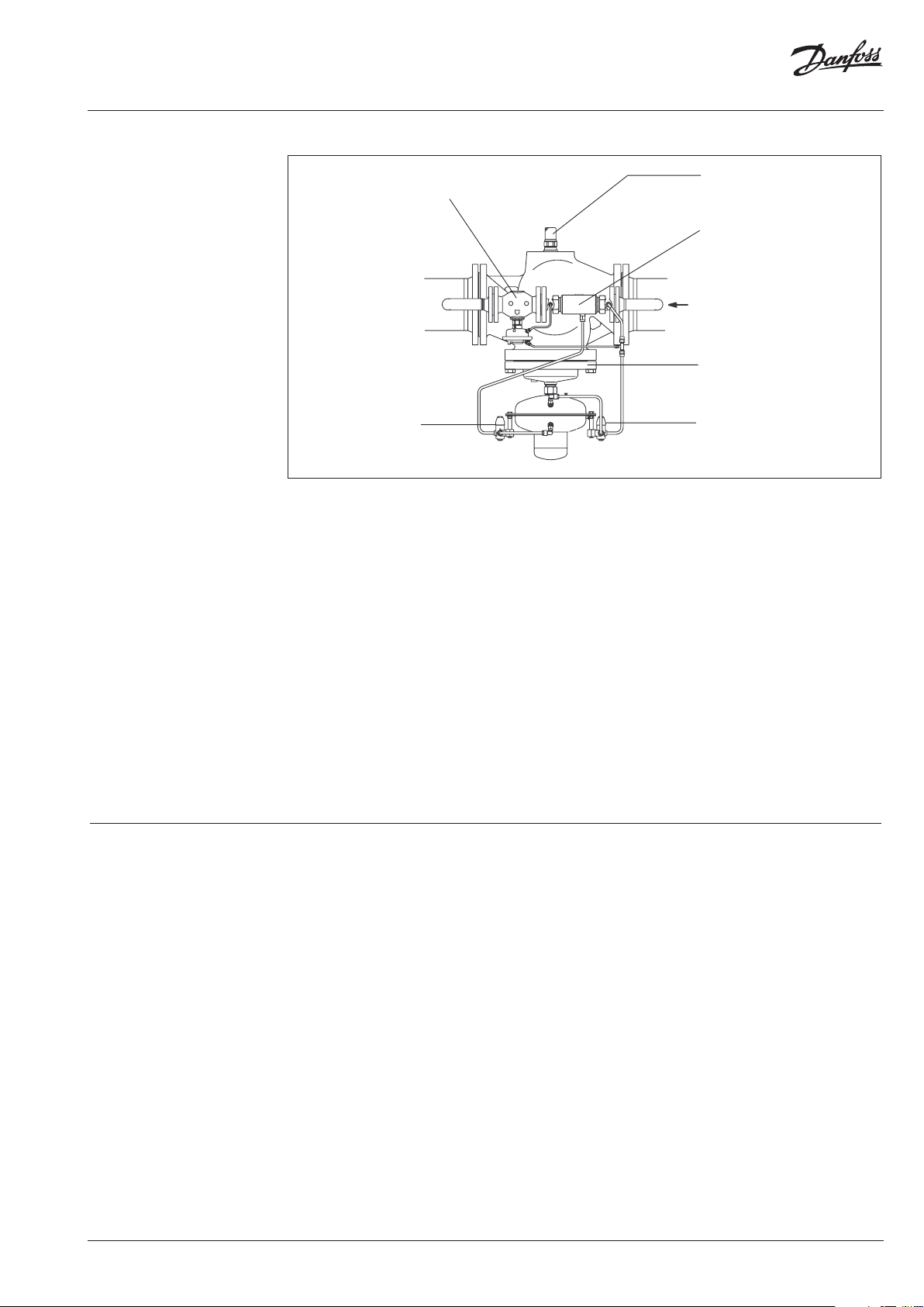
5 Scope of Delivery
DN 100, DN 125
Assembly kit valve unit PC V-VFQ 21 Pilot controller DN 25
AVP- F
Throttling element
Cu pipe Ø 6 × 1 × 1500 mm
Cu pipe Ø 10 × 1 × 3000 mm
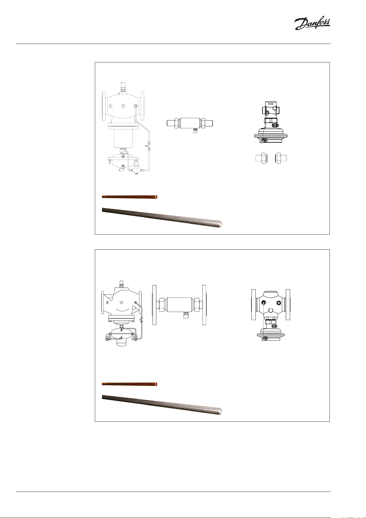
DN 150, DN 250
Assembly kit valve unit PC V-VFQ 21 Pilot controller DN 40
AVP- F
Throttling element
Cu pipe Ø 6 × 1 × 1500 mm
Cu pipe Ø 10 × 1 × 3000 mm
4 | © Danfoss | 2016.05
VI.JA.G3.02
Page 5
Instructions Pilot-controlled PCVQ DN 100 - DN 250 (PN 16, PN 25)
6 Assembly 6.1 Prior to Assembly:
Depressurized system before any
assembly work !
CAUTION!
• Clean pipeline system.
• Install strainer in front of the controller.
• Install shut-off units in front of and behind
the controller.
6.2 Installation Position, Installation Place
• Installation is only permitted in horizontal
pipelines with the actuators hanging in a
downward position.
• The controller may be installed in the supply
as well as in the return line.
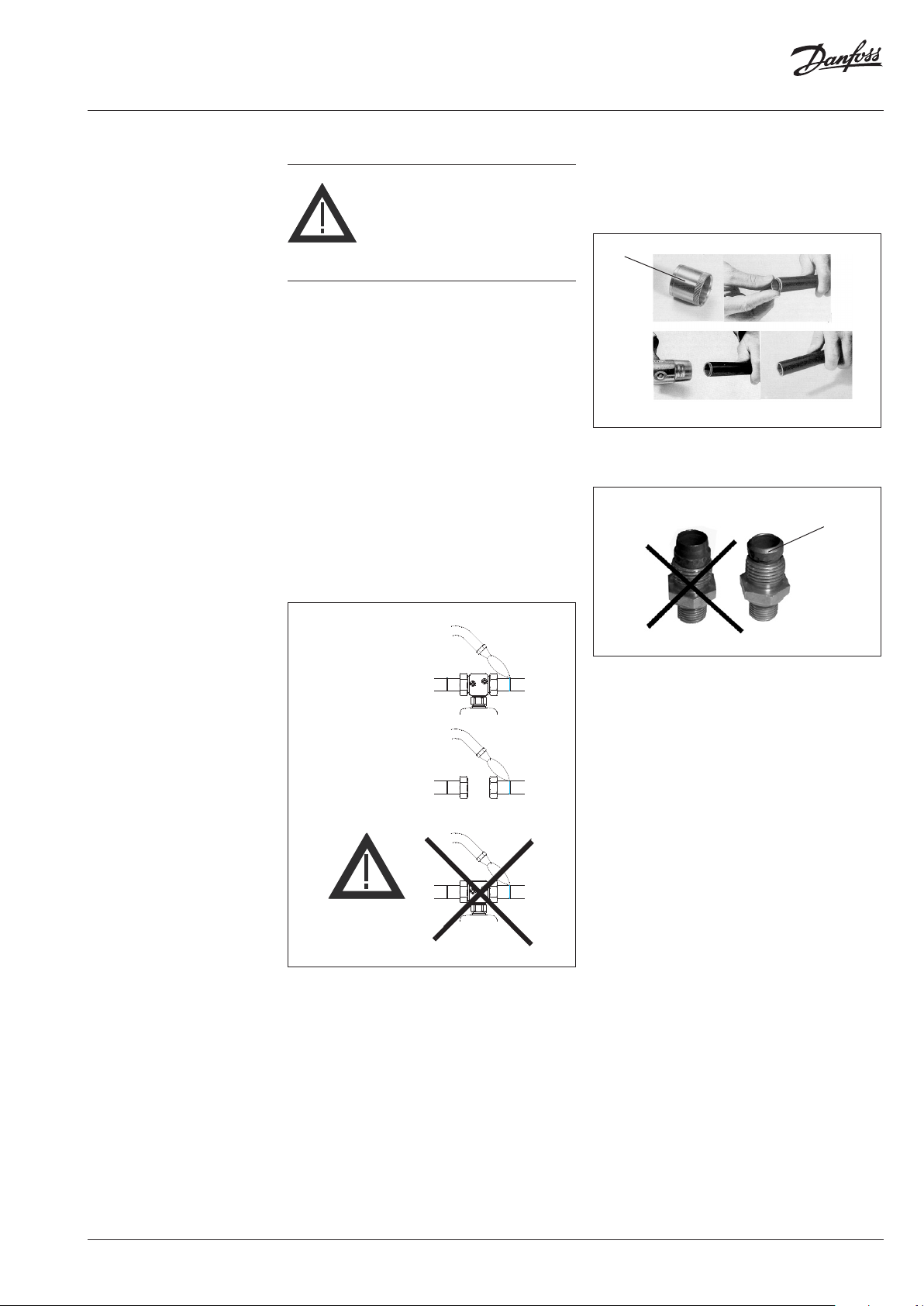
6.3 When installing:
• Observe direction of flow.
• Design with welded ends:
6.4 Impulse Tube Installation
See installation scheme, section 6.6.
For CU pipes Ø 10 × 1, insert sockets 1 on both
sides.
1
Care for correct position of the cutting rings 2.
2
pin only
weld
do NOT
weld
• Loads on the valve body and the throttle
element by the pipes are not permitted.
6.5 Insulation
The diaphragm actuators must not be insulated
when insulating system parts.
VI.JA.G3.02
© Danfoss | 2016.05 | 5
Page 6
Instructions Pilot-controlled PCVQ DN 100 - DN 250 (PN 16, PN 25)
Valve unit PCV - VFQ 21
Pilot controller AVP-F
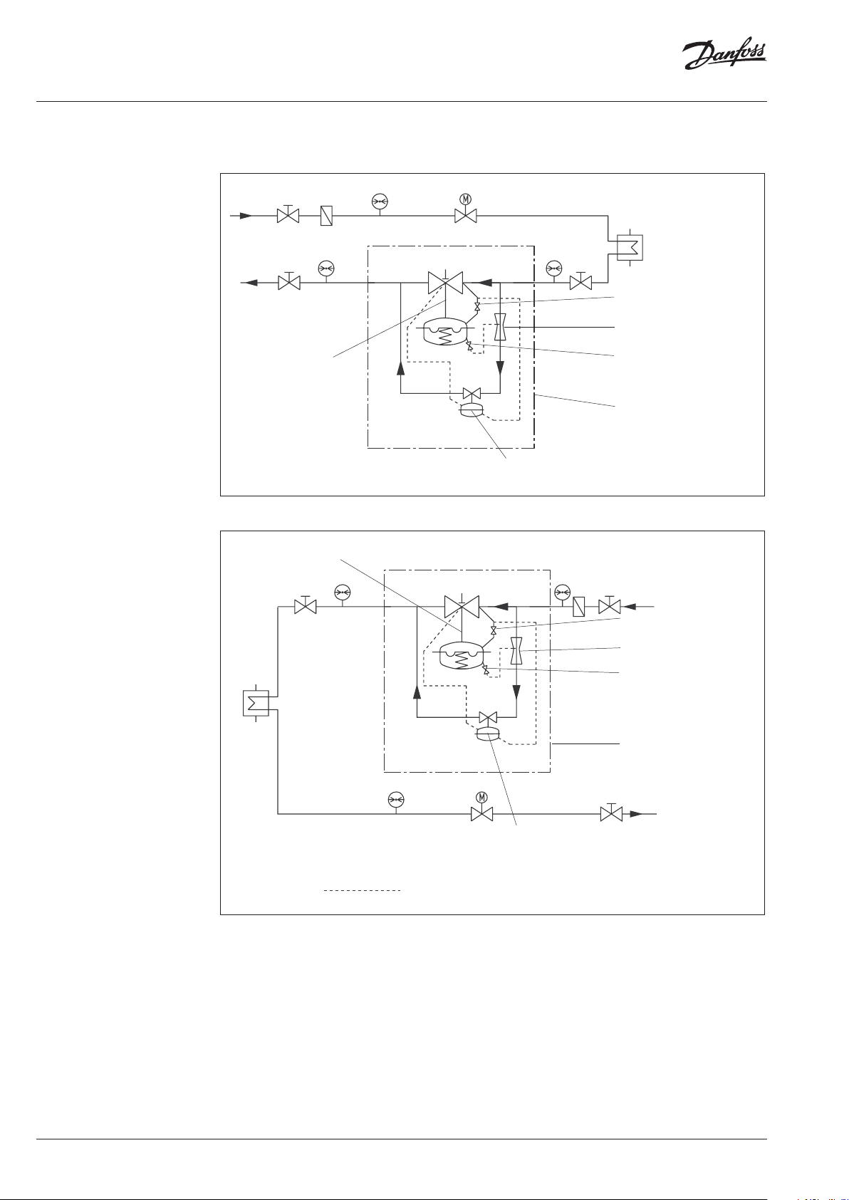
6 Assembly
6.6 Installation Scheme
Installation in the Return Line
Valve unit PCV - VFQ 21
Installation in the Supply Line
Throttling valve
Throttling
element
Throttling valve
(only by DN 150 - 250)
Bypass controller
PCVQ
Throttling valve
Throttling
element
Throttling valve
(only by DN 150 - 250)
Bypass controller
PCVQ
Pilotregler AVP-F
lay impulse tube during mounting
6 | © Danfoss | 2016.05
VI.JA.G3.02
Page 7

Instructions Pilot-controlled PCVQ DN 100 - DN 250 (PN 16, PN 25)
CU pipe Ø6×1
L1
DN 25: pipe
Material:
(not
6 Assembly 6.7 Assembly Drawings, Dimensions
DN 100 - DN 125
Lay when assembling.
D2
Cu pipe
Ø 10 × 1
Lay when assembling.
H1 H2
A
Ø33.7 × 3.2
ST 35.8
part of the delivery)
Pilot controller AVP-F
Throttling element
75
159
ca. 1000
DN 25 SW 50
160
244
VI.JA.G3.02
© Danfoss | 2016.05 | 7
Page 8

Instructions Pilot-controlled PCVQ DN 100 - DN 250 (PN 16, PN 25)
H2
assembling.
CU pipe Ø 6 × 1
DN 40: pipe Ø 48.3 × 3.2
Mater
(not part of the delivery)
6 Assembly (continuous) DN 150 - DN 250
Lay when assembling.
L1
H1
D2
B
A
200
ial: ST 35.8
Nominal
diameter
L1
H1 530 530 619 647 697
H2 - 245 300 325
D2 263 380
D1 250 320 385 500
B 200 210 310 336 412
A ≥ 290 320 350 410
ca. 1200
DN 100 125 150 200 250
350 400 480 600 730
mm
290
D1
Cu pipe
Ø 10 × 1
Lay when
8 | © Danfoss | 2016.05
VI.JA.G3.02
Page 9

Instructions Pilot-controlled PCVQ DN 100 - DN 250 (PN 16, PN 25)
p2
5
4
7 6
7 Start-up 7.1 Required Static Pressure
The static pressure p1 in front of the controller
must not fall below 1.5 bar (excess pressure).
Non-observance may lead to cavitation and
damages in the throttling element 1.
7.3 Filling the System
Note:
The controller 4 is closed when no pressure is
applied and only opens with a defined flow in the
bypass.
The pilot controller 5 is closing on rising pressure.
p1
1
This procedure guarantees that there is no
overturn of the diaphragm in the valve and the
actuators.
To avoid too high pressure
differences on the controller,
observe the following sequence
when starting-up !
7.2 Leak and Pressure Tests
To avoid too high pressures at
the diaphragm actuators, the
following should be observed
prior to any pressure tests:
Actuator of valve unit:
The admissible operating excess pressure in the
actuator 2 is 25 bar 1). For higher pressures, you
must:
• Remove the impulse tubes 3 at the actuator
and close the connections with a stopper.
• Prior to any leak or pressure test, the
instructions in section 7.3 must be complied
with.
1. Open units 6 of the system.
2. Slowly open shut-off units in the supply flow 7
and the return flow 8.
8
7.4 Start-up
During starting-up the filled system, open the
units in the same sequence as described in
section 7.3.
VI.JA.G3.02
2
7.5 Putting out of operation
When putting the system out of operation, first
close the shut-off units in the supply flow and
then those of the return flow.
3
1)
Pre-co ndition: Same pressure on bot h sides of the diaphragm.
If the pressure lo ad is one-sided, the (+)diaphragm cham ber
may have an excess p ressure of 1 bar in comparison to th e (-)
diaphragm chamber.
© Danfoss | 2016.05 | 9
Page 10

Instructions Pilot-controlled PCVQ DN 100 - DN 250 (PN 16, PN 25)
Required
flo
for the adjusting throttle
7 Start-up
7.6 Flow Rate Adjustment
The setting of the setpoint for the flow rate
limitation is made by means of flow adjusting
curves (see section 7.7) or a heat meter (see
page 33).
Adjustment by means of flow adjusting
curves
Adjustment is to be made at a shut-down system.
Procedure
1. Unscrew cover 1.
1
4. Turn the adjusting throttle by this number of
rotations to the left.
5. The adjusted flow rate can be verified by
means of a flow rate measuring device.
Perhaps you need to re-adjust the flow rate.
Care for an adequate differential pressure in
the system.
6. Tighten the counter nut without changing the
position of the adjusting throttle.
2. Loosen the counter nut 2.
2
2. Screw.in the adjusting throttle 3 to its stop.
3
3. Choose diagram,
(see section 7.7, Flow Adjusting Curves)
Observe effecitve pressure Δpb: 0.2 or 0.5 bar
see rating plate on the actuator AVP-F
7. Re-screw the cap nut 1.
8. The cap nut can be sealed.
10 | © Danfoss | 2016.05
w rate
The flow rate adjustment is completed.
Now, adjust the differential pressure,
see section 7.8.
Read rotations
VI.JA.G3.02
Page 11

Instructions Pilot-controlled PCVQ DN 100 - DN 250 (PN 16, PN 25)
DN 100kvs 125/DN 125kvs 160/DN 150kvs 320
314
Rotations for the adjusting throttle
Flow rate (m
3
/h)
DN 100kvs 125/DN 125kvs 160/DN 150kvs 320
314
Rotations for the adjusting throttle
Flow rate (m
3
/h)
DN 200kvs 450/DN 250kvs 630
adjusting throttle: 4
required flow rate
limitation:
DN 200kvs 450/DN 250kvs 630
89
Rotations for the adjusting throttle
Flowrate (m
3
/h)
7 Start-up
7.7 Flow Adjusting Curves
140
p
=0,2
∆
120
100
80
60
40
20
0
200
180
160
140
/h)
3
120
Flowrate (m
100
80
60
40
20
0
b
01234567891011121
DN 250
0123456789 10
Rotations for the adjusting throttle
DN150
DN100/ 125
DN 200
p
=0,2
b
220
200
p
=0,5
∆
b
180
DN 250
DN150
DN100/ 125
DN 200
p
=0,5
∆
b
160
140
120
100
80
60
40
20
0
012345678 91011121
260
240
220
200
180
160
140
120
100
80
60
40
20
0
012345 67
VI.JA.G3.02
Example
Ventil DN 200
100 m³/h
necessary
rotations of the
© Danfoss | 2016.05 | 11
Page 12

Instructions Pilot-controlled PCVQ DN 100 - DN 250 (PN 16, PN 25)
P2
2
3
7 Start-up
Adjustment by means of a flow rate
measuring device:
Procedure
1. Prior to the adjustment of the flow rate,
start the system in accordance with the
instructions given in section 7.4.
2. The shut-off units 1 and the control units 2
must be completely opened so that the flow
rate is not restricted by a unit.
The adjustment can also be carried out via a
bypass 3.
P1
1
PCVQ
5. Adjust the flow rate limitation by turning the
adjusting throttle 6:
Turning to the right 7, reduces the flow rate.
7
6
Turning to the left 8, increases the flow rate.
8
3. Unscrew cap nut 4.
4
4. Loosen the counter nut 5.
6. Observe the flow rate indicator.
7. After having completed the adjustment,
tighten the counter nut without changing the
position of the adjusting throttle.
8. Re-screw the cap nut.
5
9. The cap nut can be sealed.
12 | © Danfoss | 2016.05
The flow rate adjustment is completed.
VI.JA.G3.02
Page 13

Instructions Pilot-controlled PCVQ DN 100 - DN 250 (PN 16, PN 25)
1
Tu
to the lef
reduces
damping
:
7 Start-up
7.8 Sealing
The setpoint adjuster may be sealed.
7.9 Adjustment of the Throttle Valves
Number of throttle valves:
DN 100, 125: 1 ×
DN 150-250 : 2 ×
• Unscrew cover 1.
7.10 Fu nction Tes t
Flow rate
The adjusted flow rate must not be exceeded if
the system is completely open.
If the setting is exceeded in either direction,
check the adjustment as described in section 7.5.
rning
t:
• Standard adjustment:
Turn in the valve spindle by turning it to the
right by means of a wrench SW5 to its stop.
Then unscrew valve spindle by turning it to
the left by approx. 10 rotations.
• Increase of damping, e.g. necessary in case
of pressure vibrations.
Screw in the valve spindle by turning it to the
right.
• Reduction of damping, e.g. in case of a
control that is too slug.
Unscrew the valve spindle by turning it to the
left.
Turning
to the right
increases
damping
VI.JA.G3.02
© Danfoss | 2016.05 | 13
Page 14

Instructions Pilot-controlled PCVQ DN 100 - DN 250 (PN 16, PN 25)
8 Trouble Shooting
Fault Possible cause Remedy
Controller does
not hold the flow
rate on a
constant level
Throttle valve is open too widely. Slightly close the throttle valve,
see section 7.10.
Air in the actuators 1. Loosen impulse tube connections at
the actuators by approx. 1 rotation.
2. Deaerate, Caution hot water !
(move impulse tube until medium
penetrates).
3. Tighten impulse tube connections.
Impulse tubes or impulse tube
connections are dirty or damaged.
1. Remove impulse tube.
2. Clean impulse tubes and impulse
tube connections and check for free
passage.
Flow rate is too low Valve plug of the pilot valve AVP-F
does not open:
Valve seat or plug is dirty or damaged, trim
is dirty.
1. Remove impulse tube.
2. Dismount actuator and trim.
Procedure, see section 9.4.
3. Clean seat and plug.
4. If damaged, replace trim or valve.
Valve plug of the pilot valve VFQ 21
does not open:
Valve seat or plug is dirty or damaged,
trim is dirty.
1. Remove impulse tube.
2. Dismount actutor and trim 1 ).
Procedure, see sections 9.1 and 9.2.
3. Clean seat and plug.
4. If damaged, replace trim or valve.
Rolling diaphragm in the actuator of the
valve unit is defective, i.e. valve VFQ 21
does not open.
1. Remove impulse tube.
2. Loosen union nut SW 46 and remove
actuator, see also section 9.1.
3. Replace actuator.
1)
The trim ca n be replaced by qualified pe rsonnel up to DN 125.
From DN 150 replacement sho uld be carried out by the Danf oss service personnel .
14 | © Danfoss | 2016.05
VI.JA.G3.02
Page 15

Instructions Pilot-controlled PCVQ DN 100 - DN 250 (PN 16, PN 25)
9 Replacement of Valve,
Actuator, Trims
9.1 Dismounting and Mounting Actuator and
Valve
Note:
The springs 1 in the actuator are pre-stressed.
Therefore, the actuator must be pushed upwards
to be dismounted. You need a second person to
do this.
Valve unit DN 100–125
3
2
5
4
1
Prior to assembly check cone 5 !
5
grease
1. Clean cone prior to mounting.
2. Check O rings for damages, in case of
damages, replace cone (see Spare Parts).
3. Grease cone with high-performance fitting
component: BARRIERTA L55/3 HV
(see Spare Parts).
Mounting
1. Place actuator at the valve and push
upwards.
2. Screw on union nut 2.
3. Align actuator, observe position of impulse
tube connections.
4. Tighten union nut 1, max. torque 100 Nm.
Cone
Valve stem 3 and the stem of the actuator 4 are
not screwed to eachother.
Dismounting
1. Dismount impulse tubes.
2. Support actuator below or by a second
person as the springs 1 are pre-stressed.
3. Loosen union nut 2.
4. Remove actuator.
VI.JA.G3.02
© Danfoss | 2016.05 | 15
Page 16

Instructions Pilot-controlled PCVQ DN 100 - DN 250 (PN 16, PN 25)
9 Replacement of Valve,
Actuator, Trims
Valve unit DN 150–250
3
1
Turn actuator
to the left
The stem of the actuator 4 is screwed into the
valve stem 3.
Dismounting
1. Dismount impulse tubes.
2. Completely loosen union nut 1.
The actuator hangs on the screwed-in
stem 4.
4
Then, return the actuator by
approx. 1 rotation (to the left)
3. Align actuator, observe position of the control
lines connections.
4. Tighten union nut 1, torque 100 Nm.
The actuator weights approx.
20 kg. In addition, an internal
spring package is pre-stressed.
Secure against dropping down
before unscrewing.
3. Screw the stem of the actuators 4 out of the
valve stem 3 by turning the actuator to the
left.
Mounting
1. Place actuator at the valve and push upward
to press the spring package in the actuator
together (second person necessary).
2. Carefully turn actuator to the right.
By this, carefully screw in the stem of the
actuator into the valve stem to its stop.
16 | © Danfoss | 2016.05
VI.JA.G3.02
Page 17

Instructions Pilot-controlled PCVQ DN 100 - DN 250 (PN 16, PN 25)
9 Replacement of Valve,
Actuator, Trims
9.2 Replacement of Trim Valve VFQ 21
The trim can be replaced by qualified personnel
up to DN 125. From DN 150 replacement should
be carried out by the Danfoss service personnel.
Removing the trim:
Valves DN 100–125
2
4
3
1
Installing the trim:
Mounitng is carried out in reverse order.
Torque hexagon head cap screws 2:
DN Torque Wrench
100 - 125 180 Nm SW 30
1. Dismount actuator 1
(see section 9.1).
2. Unscrew hexagon head cap screw 2.
3. Remove bonnet 3.
4. Take out trim 4.
Prior to installation:
Clean sealing surfaces 5 and socket 6, grease
sealing surfaces with antiseize graphite
petroleum.
5
6
VI.JA.G3.02
© Danfoss | 2016.05 | 17
Page 18

Instructions Pilot-controlled PCVQ DN 100 - DN 250 (PN 16, PN 25)
9 Replacement of Valve,
Actuator, Trims
9.3 Dismounting, Mounting
Actuator AVP-F
Dismounting
1. Dismount impulse tubes.
2. Loosen union nut 1.
3. Remove actuator.
Mounting
1. Place actuator at the valve and align,
observe position of the impulse tube
connections.
2. Screw on union nut 1 and tighten,
torque 100 Nm.
9.4 Replacement of Trim
Valve AVP-F
2
1
AVP-F DN 25
18 | © Danfoss | 2016.05
2
AVP-F DN 40
Dismounting
1. Unscrew actuator (see above).
2. Unscrew trim 2.
DN 25: with pipe tongs, wrap gum strips
around the trim
DN 40: with wrench SW 55
3. Pull out trim.
Mounting
Mounting is carried out in reverse order. Only
tighten with low torque, sealing is made with
O rings.
VI.JA.G3.02
Page 19

Instructions Pilot-controlled PCVQ DN 100 - DN 250 (PN 16, PN 25)
VI.JA.G3.02
© Danfoss | 2016.05 | 19
Page 20

Danf
already on order pro
All trademarks in this material are property of the respec
Instructions Pilot-controlled PCVQ DN 100 - DN 250 (PN 16, PN 25)
oss can accept no responsibility for possible errors in catalogues, brochures and other printed material. Danfoss reserves the right to alter its products without notice. This also applies to products
vided that such alterations can be made without subsequential changes being necessary eady agreed.
20 | © Danfoss | DHS-SRMT/SI | 2016.05
tive companies. Danfoss and the Danfoss logotype are trademarks of Danfoss A/S. All rights reserved.
73696700/VI.JA.G3.02
 Loading...