

Page 1
Instructions
Pilot-controlled Flow Rate and Differential Pressure
Controller PCVPQ
English Page 2
Instructions
Hilfsgesteuerter Volumenstrom-, Differenzdruckregler
PCVPQ
Deutsch Page 21
DN 100 - DN 250
PN 16 / PN 25
© Danfoss | 2016.05
VI.JA.H3.5B | 1
Page 2

Instructions PCVPQ
Table of Contents 1 Safety Notes ....................................................... 3
2 Definition of Application ............................. 3
3 Description ........................................................... 4
3.1 Construction ..........................................................4
3.2 Mode of Operation ............................................4
4 Technical Data ................................................... 4
5 Scope of Delivery .............................................. 5
6 Assembly .............................................................. 6
6.1 Prior to Assembly ................................................ 6
6.2 Installation Position,
Installation Place ................................................. 6
6.3 When Installaling observe ...............................6
6.4 Impulse Tube Installation ................................. 6
6.5 Insulation ............................................................... 6
6.6 Installation Scheme ............................................ 7
6.7 Assembly Drawings, Dimensions ................. 8
7 Start-up ................................................................10
7.1 Required static Pressure, Pressure
Difference ............................................................10
7.2 Leak and Pressure Test .....................................10
7.3 Filling the System ..............................................10
7.4 Start-up ..................................................................10
7.5 Putting out of Operation ................................10
7.6 Flow Rate Adjustment ......................................11
7.7 Flow Adjusting Curves .................................... 12
7.8 Adjustment of
the Differential Pressure ................................14
7.9 Sealing ..................................................................14
7.10 Adjustement of
the Throttle Valves ...........................................14
7.11 Funstion Test ......................................................15
8 Trouble Shooting ...........................................16
9 Replacement of Valve,
Actuator, Trims ................................................ 17
2 | © Danfoss | 2016.05
9.1 Dismounting and Mounting
Actuator Valve ....................................................17
9.2 Replacement of Trim Valve VFQ 21 ............19
9.3 Dismounting, Mounting
Actuator AVP, AVP-F .........................................20
9.4 Replacement of
Trim Valve AVP, AVP-F .......................................20
VI.JA.H3.5B
Page 3
Instructions PCVPQ
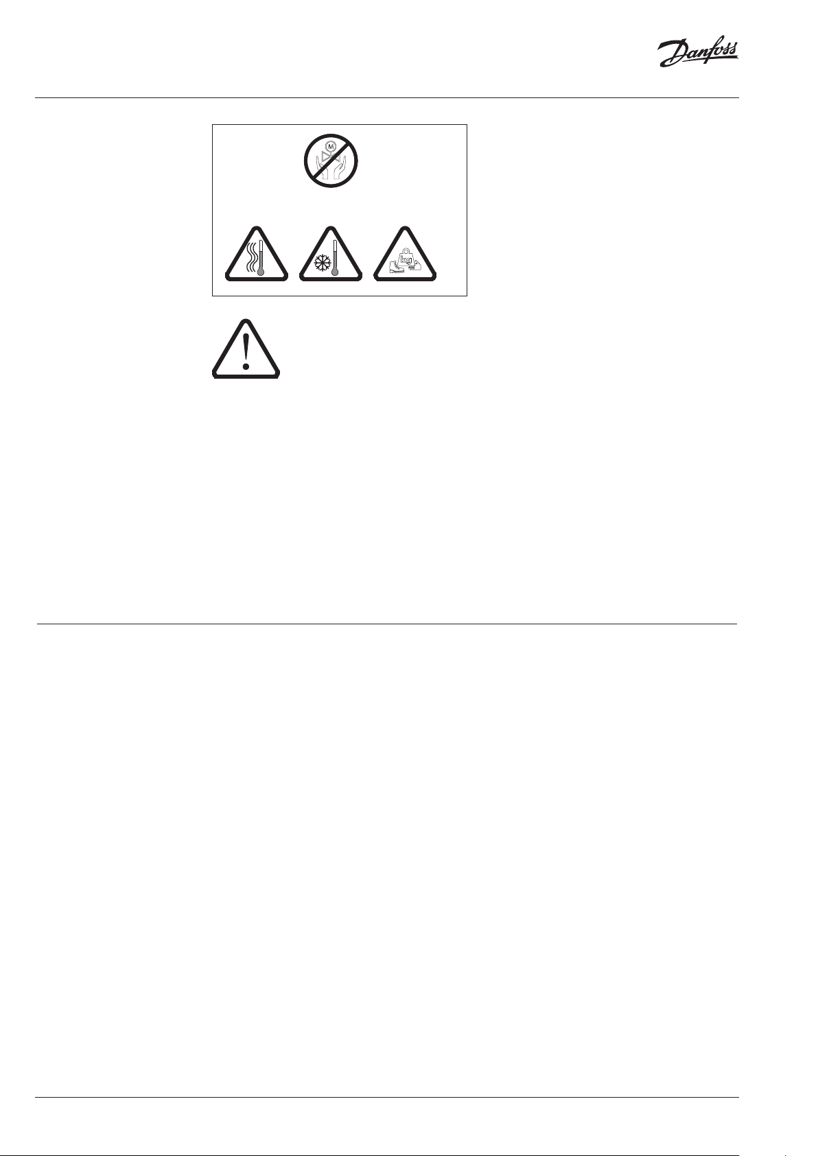
1 Safety Notes
observe these instructions.
Necessary assembly, start-up, and maintenance
work must be performed only by qualified,
trained and authorized personnel.
Prior to assembly and maintenance work on the
controller, the system must be:
depressurized,
cooled down,
emptied and
cleaned.
Please comply with the instructions of the
system manufacturer or system operator.
MAINTENANCE
FREE
Prior to assembly and
commissioning to avoid injury
of persons and damages of the
devices, it is absolutely
necessary to carefully read and
2 Definition of
Application
The controller is used for flow rate limitation of
water for heating, district heating and cooling
systems.
The admissible medium temperatures depend
on the design and comprise 5-150 °C,
5-200 °C.
The technical data on the rating plates determine the use.
VI.JA.H3.5B
© Danfoss | 2016.05 | 3
Page 4
Instructions PCVPQ
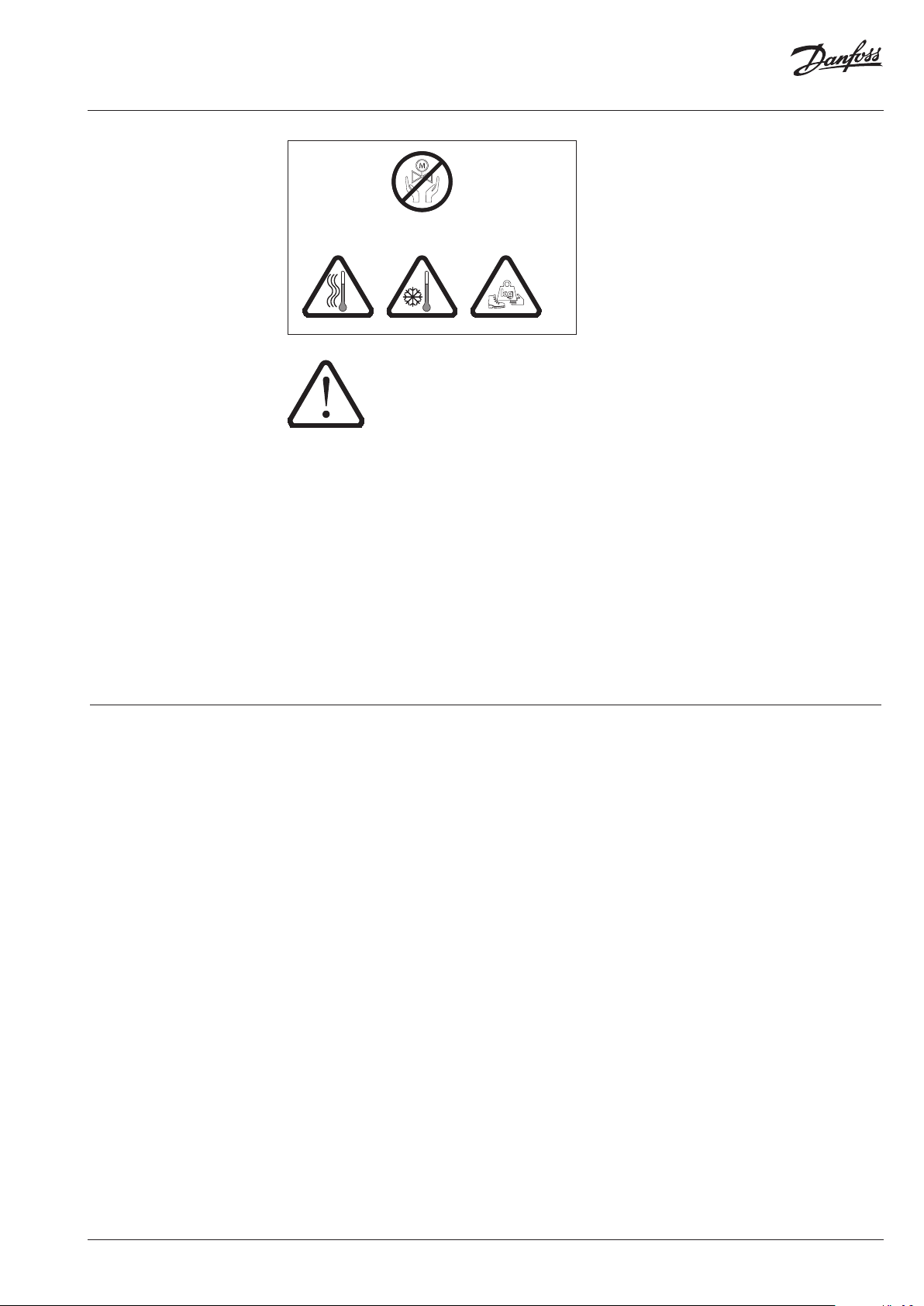
P
(Diff
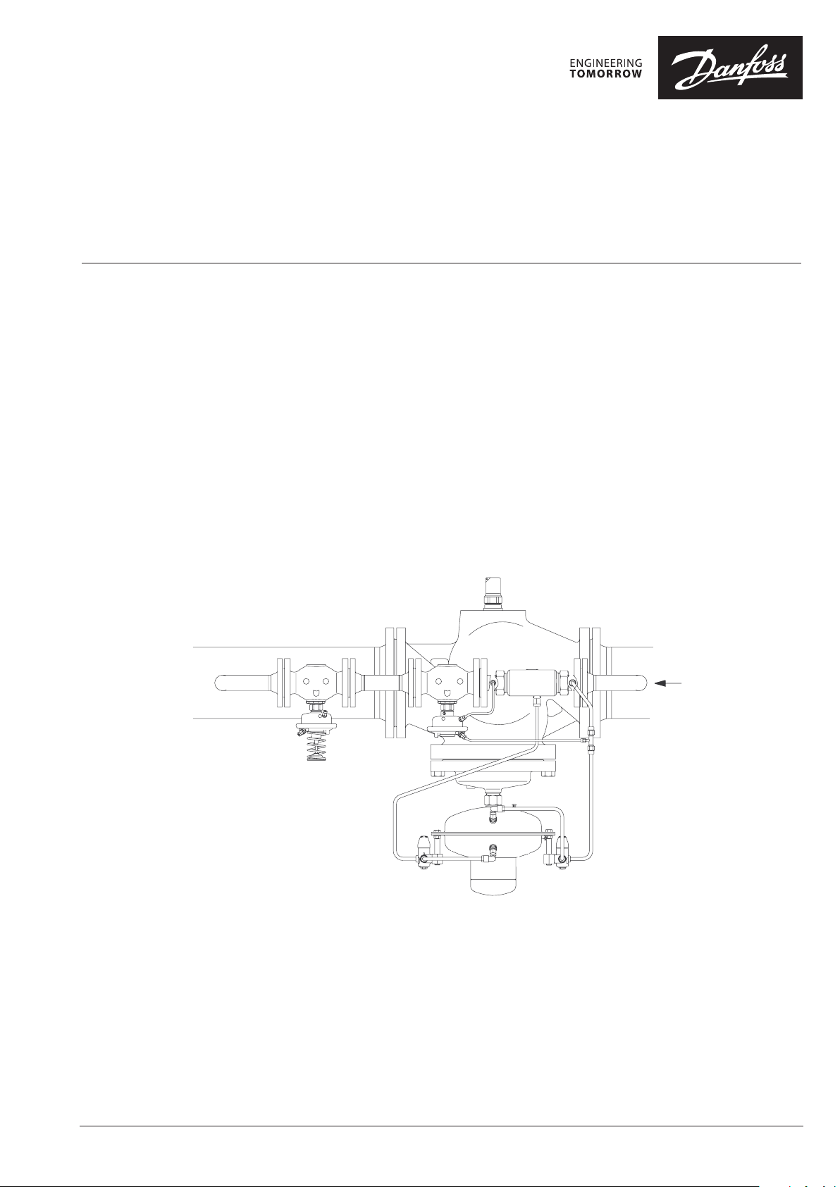
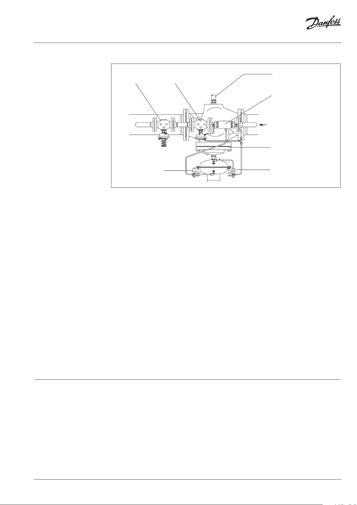
3 Description
3.1 Construction
ilot controller AVP
erential Pressure)
Throttling valve
only by DN150-250
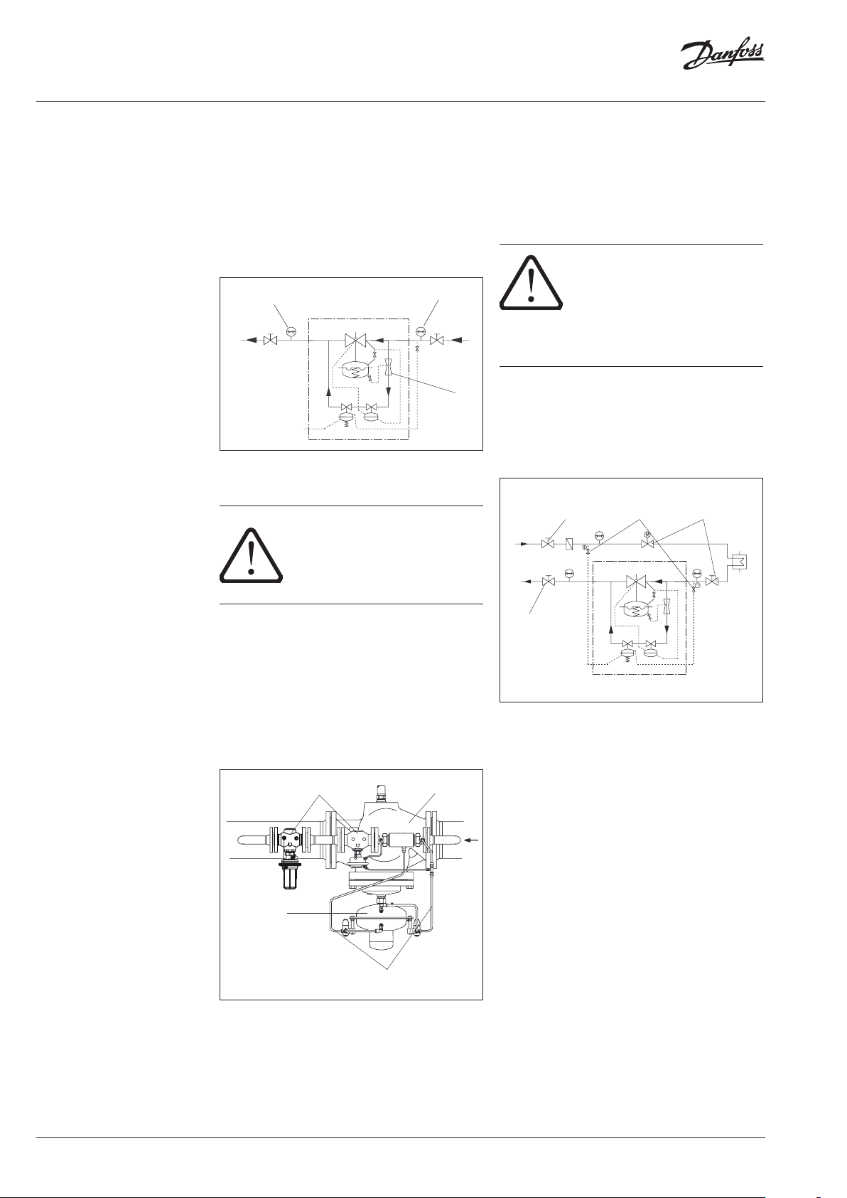
3.2 Mode of Operation
The control unit consists of the PCV-VFQ21
valve unit, installed in the main pipe, and the
differential pressure controllers AVP and AVP-F
installed as pilot controllers in the bypass. In the
bypass line, a throttle element is installed in front
of the pilot controllers.
The controller keeps the differential pressure
for the corresponding section on a constant
level and restricts the flow rate to the adjusted
setpoints.
The valve and the pilot valves are pressurebalanced.
The setpoint for the differential pressure is
adjusted by pre-stressing the setpoint spring
of the pilot controller AVP. The setpoint for the
flow rate limitation is adjusted at the adjusting
throttle of the valve unit.
The valve unit in the main pipe is opening on
rising pressure. The pilot controllers in the
bypass line are closing on rising pressure.
Differential Pressure Control
In case of small flow rates, the valve in the main
pipe remains closed through the pressure spring
Pilot controller AVP-F
(Flow Rate)
Adjusting throttle
Throttling element DE
Valve unit PCV-VFQ 21
Throttling valve
in the actuator of the valve unit. The pressure is
exclusively controlled by the pilot controller.
If the flow rate in the bypass is increased, the
pressure in the throttle element (Venturi nozzle)
decreases.
The reduced pressure acts through an impulse
tube upon the lower chamber of the actuator
of the valve unit. The main valve is thus opened
shock-free and continuously.
If the flow rate is reduced, the pressure in the
throttle element raises and the main valve closes.
This sequential switching guarantees an
operation free of vibrations and a small control
deviation over a wide positioning range.
Flow Rate Limitation
If the flow rate reaches the adjusted setpoint, the
differential pressure increases at the adjusting
throttle. This differential pressure acts on the
actuator AVP-F via the impulse tubes and the
valve AVP-F closes. Consequently, the valve of
the valve unit is throttled, too, and the flow rate
is restricted.
4 Technical Data Technical data, see rating plates and the PCV
data sheet.
4 | © Danfoss | 2016.05
VI.JA.H3.5B
Page 5
Instructions PCVPQ
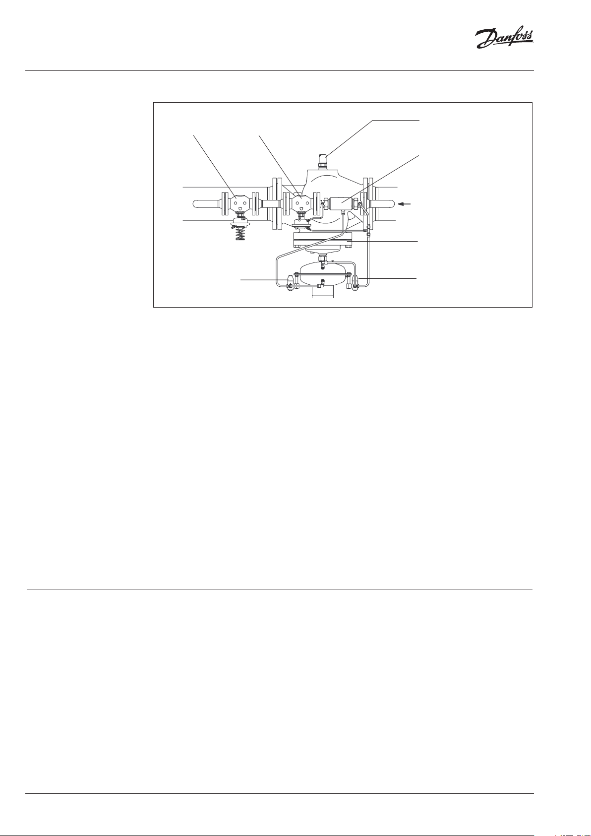
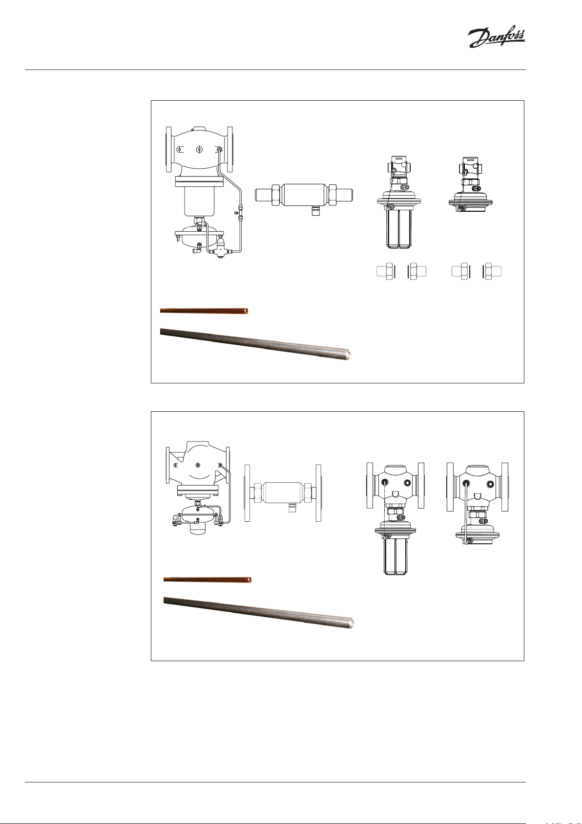
5 Scope of Delivery
DN 100-125
Assembly kit valve unit PCV-VFQ 21 Pilot controller DN 25
AVP
DN 25
Throttling element
Cu pipe Ø 6 × 1 × 1500 mm
Cu pipe Ø 10 × 1 × 3000 mm
AVP- F
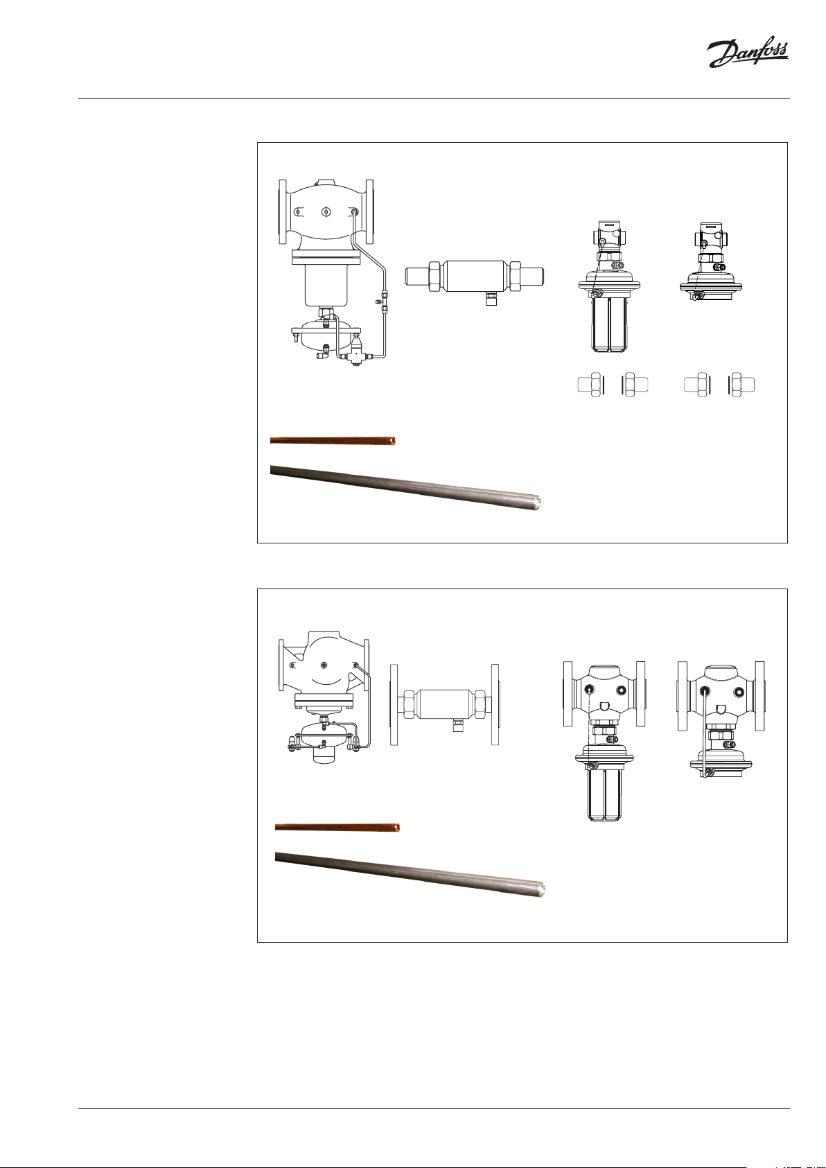
DN 150-250
Assembly kit valve unit PCV-VFQ 21 Pilot controller DN 40
AVP
DN 40
Throttling element
Cu pipe Ø 6 × 1 × 1500 mm
Cu pipe Ø 10 × 1 × 3000 mm
AVP- F
VI.JA.H3.5B
© Danfoss | 2016.05 | 5
Page 6
Instructions PCVPQ
6 Assembly 6.1 Prior to Assembly:
Depressurized system before
any assembly work !
CAUTION!
• Clean pipeline system.
• Install strainer in front of the controller.
• Install shut-off units in front of and behind
the controller.
6.2 Installation Position, Installation Place
• Installation is only permitted in horizontal
pipelines with the actuators hanging in a
downward position.
• The controller may be installed in the supply
as well as in the return line.
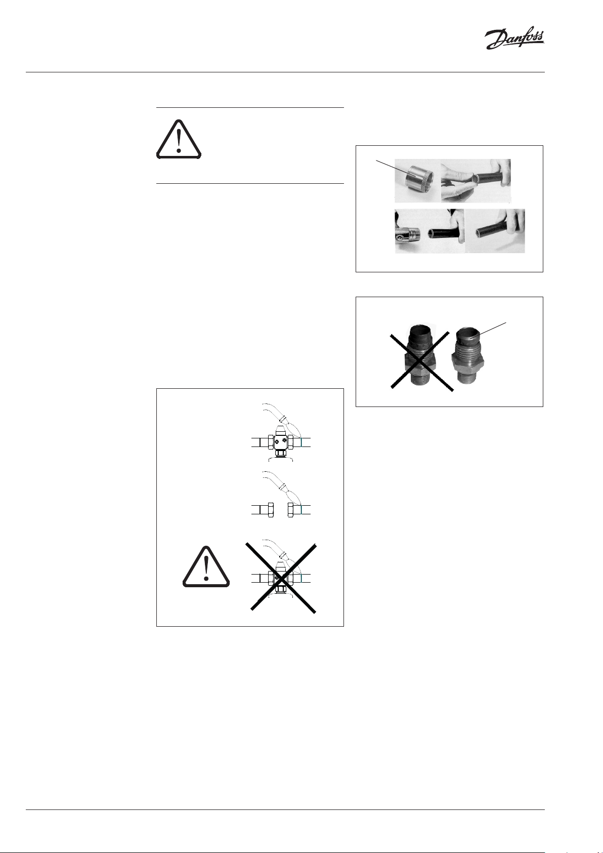
6.3 When installing:
• Observe direction of flow.
• Design with welded ends:
6.4 Impulse Tube Installation
See installation scheme, section 6.6.
For CU pipes Ø 10 × 1, insert sockets 1 on both
sides.
1
Care for correct position of the cutting rings 2.
2
pin only
weld
do NOT
weld
• Loads on the valve body and the throttle
element by the pipes are not permitted.
6.5 Insulation
The diaphragm actuators must not be insulated
when insulating system parts.
6 | © Danfoss | 2016.05
VI.JA.H3.5B
Page 7
Instructions PCVPQ
Valve unit PCV - VFQ 21
lay impulse tube during mounting
250)
Pilot controller AVP-F
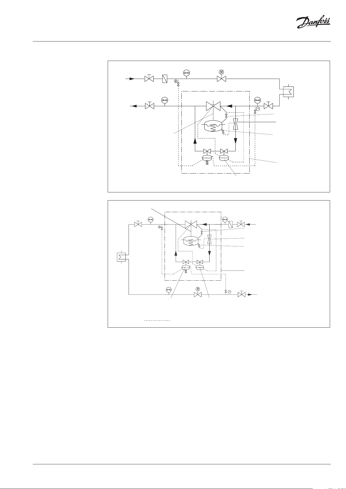
6 Assembly 6.6 Installation Scheme
Valve unit PCV - VFQ 21
Installation in the Return Line
Throttling valve
Throttling
element
Throttling valve
(only by DN 150 -
Bypass controller
PCVPQ
Installation in the Supply Line
Pilotregler AVP-F
Pilotregler AVP-F
Throttling valve
Throttling
element
Throttling valve
(only by DN 150 - 250)
Bypass controller
PCVPQ
VI.JA.H3.5B
© Danfoss | 2016.05 | 7
Page 8
Instructions PCVPQ
CU pipe Ø 6 x 1
DN 25: pipe
Mater
(not
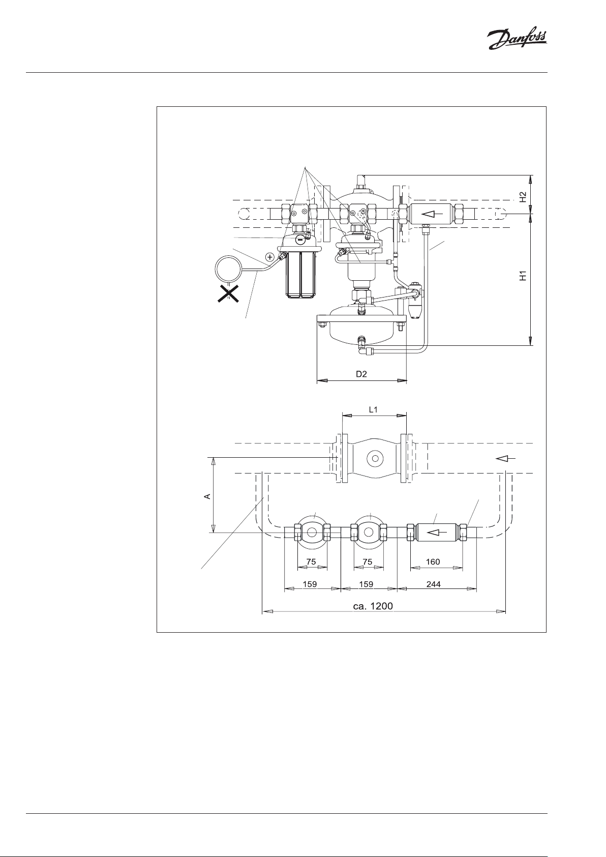
6 Assembly
6.7 Assembly Drawings, Dimensions
Lay when assembling.
to the return flow
to the supply flow
Install impulse tubes
laterally because of dir t
Cu pipe
Ø 10 x 1
Lay when assembling.
DN 100-125
Ø 33.7 x 3.2
ial: ST 35.8
part of the delivery)
Pilot controller AVP
Pilot controller
AVP-F
Throttling
element
DN 25 SW 50
8 | © Danfoss | 2016.05
VI.JA.H3.5B
Page 9
Instructions PCVPQ
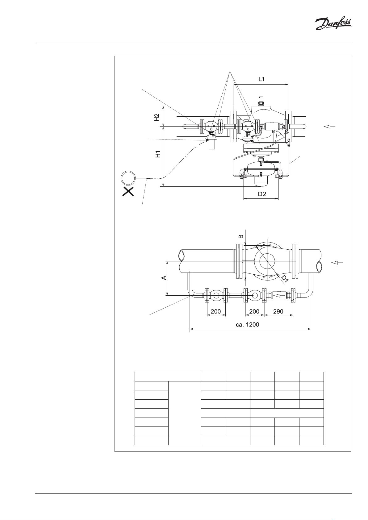
laterally because of dirt
CU pipe Ø 6 x 1
DN 40: pipe
Mater
(not part of the delivery)
6 Assembly
to the return flow
to the supply flow
Install impulse tubes
Lay when assembling.
Cu pipe
Ø 10 x 1
Lay when assembling.
DN 150-250
Ø 48.3 x 3.2
ial: ST 35.8
Dimensions
Nominal diameter DN 100 125 150 200 250
L1
350 400 480 600 730
H1 530 530 619 647 697
H2 - 245 300 325
D2 263 380
mm
D1 150 250 320 385 500
B 200 210 310 336 412
A ≥ 290 320 350 410
VI.JA.H3.5B
© Danfoss | 2016.05 | 9
Page 10
Instructions PCVPQ
5
4
3
p2 p1
867
7 Start-up
7.1 Required Static Pressure, Pressure
Difference
For a proper functioning, a minimum pressure
difference of p1 - p2 ≥ 0.5 bar is required.
The static pressure p1 in front of the controller
must not fall below 1.5 bar (excess pressure).
Nonobservance may lead to cavitation and
damages in the throttling element 1.
1
7.2 Leak and Pressure Tests
To avoid too high pressures at
the diaphragm actuators, the
following should be observed
prior to any pressure tests:
7.3 Filling the System
Note:
The controller 4 is closed when no pressure is
applied and only opens with a defined flow in the
bypass.
The pilot controller 5 is closing on rising pressure.
To avoid too high pressure
differences on the controller,
observe the following sequence
when starting-up !
This procedure guarantees that there is no
overturn of the diaphragm in the valve and the
actuators.
1. Open shut-off valves 6 that possibly exist in
the impulse tubes.
2. Open units 7 of the system.
3. Slowly open shut-off units in the supply
flow 8 and the return flow 9.
Actuator of valve unit:
The admissible operating excess pressure in the
actuator 2 is 25 bar 1). For higher pressures, you
must:
• Remove the impulse tubes 3 at the actuator
and close the connections with a stopper.
• Prior to any leak or pressure test, the
instructions in section 7.3 must be complied
with.
2
1)
Pre-condi tion: Same pressure on both side s of the diaphragm.
If the pressure lo ad is one-sided, the (+)diaphragm cham ber
may have an excess p ressure of 1 bar in comparison to th e (-)
diaphragm chamber.
9
7.4 Start-up
During starting-up the filled system, open the
units in the same sequence as described in
section 7.3.
7.5 Putting out of operation
When putting the system out of operation, first
close the shut-off units in the supply flow and
then those of the return flow.
10 | © Danfoss | 2016.05
VI.JA.H3.5B
Page 11
Instructions PCVPQ
Required
flo
for the adjusting throttle
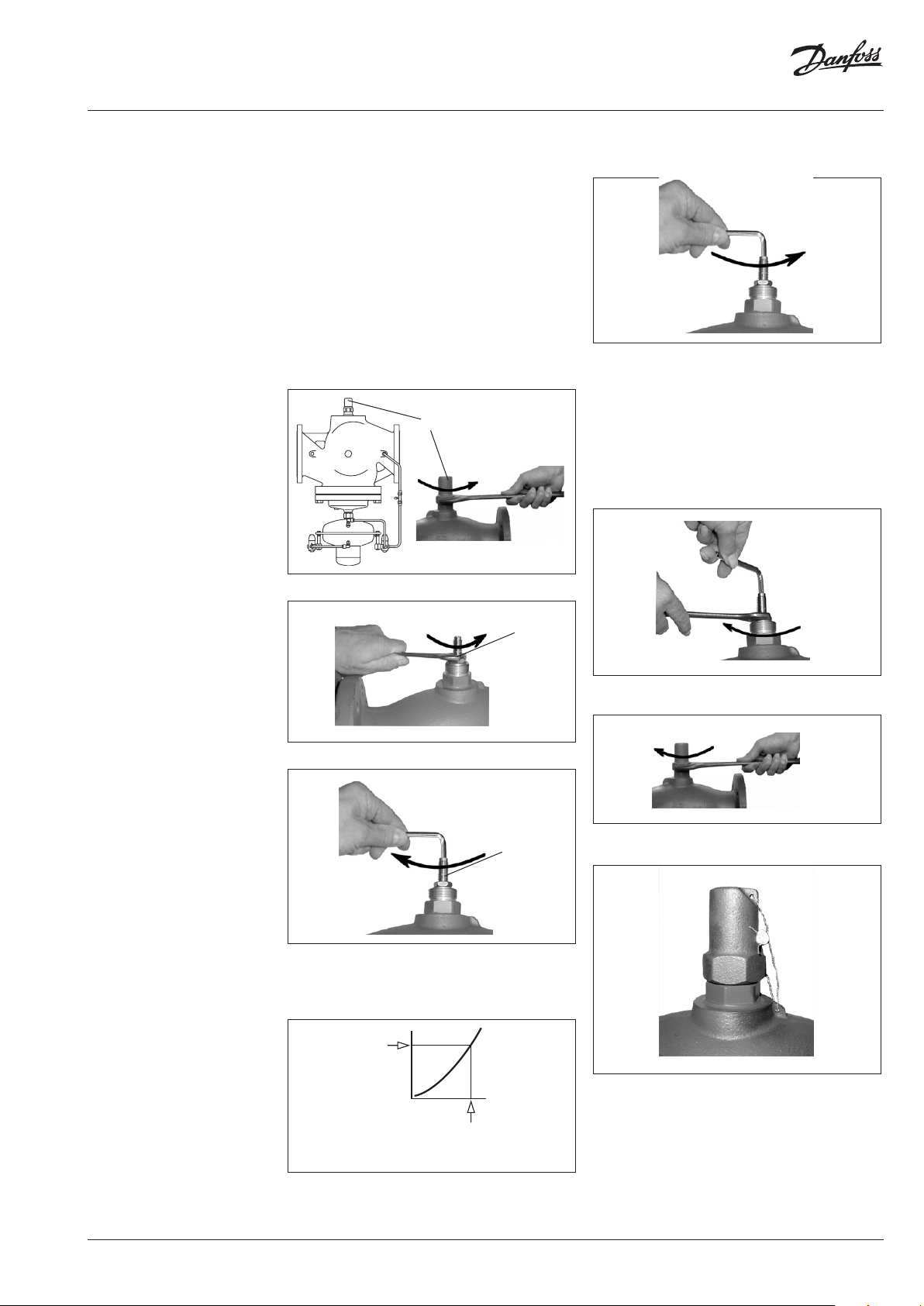
7.6 Flow Rate Adjustment
The setting of the setpoint for the flow rate
limitation is made by means of flow adjusting
curves (see section 7.7) or a heat meter (see page
33).
Adjustment by means of flow adjusting
curves
Adjustment is to be made at a shut-down system.
Procedure
1. Unscrew cover 1.
1
2. Loosen the counter nut 2.
4. Turn the adjusting throttle by this number of
rotations to the left.
5. The adjusted flow rate can be verified by
means of a flow rate measuring device.
Perhaps you need to re-adjust the flow rate.
Care for an adequate differential pressure in
the system.
6. Tighten the counter nut without changing the
position of the adjusting throttle.
2
2. Screw in the adjusting throttle 3 to its stop.
3
3. Choose diagram,
(see section 7.7, Flow Adjusting Curves)
Observe effecitve pressure Δpb: 0.2 or 0.5 bar
see rating plate on the actuator AVP-F
w rate
7. Re-screw the cap nut 1.
8. The cap nut can be sealed.
VI.JA.H3.5B
The flow rate adjustment is completed.
Now, adjust the differential pressure,
see section 7.8.
Read rotations
© Danfoss | 2016.05 | 11
Page 12
Instructions PCVPQ
DN 100kvs 125/DN 125kvs 160/DN 150kvs 320
14
Rotations for the adjusting throttle
Flow rate (m
3
/h)
DN 100kvs 125/DN 125kvs 160/DN 150kvs 320
14
Rotations for the adjusting throttle
Flow rate (m
3
/h)
DN 200kvs 450/DN 250kvs 630
10
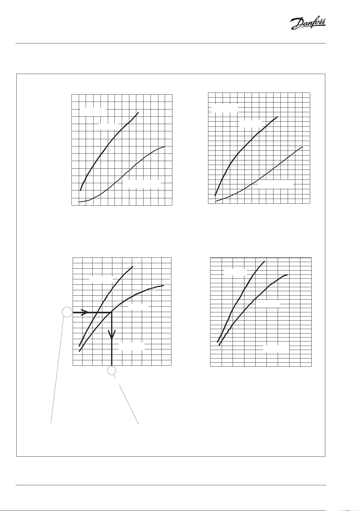
adjusting throttle: 4
required flow rate
limitation:
DN 200kvs 450/DN 250kvs 630
89
Rotations for the adjusting throttle
Flowrate (m
3
/h)
7 Start-up
7.7 Flow Adjusting Curves
140
p
=0,2
120
100
80
60
40
20
0
200
180
160
140
/h)
3
120
100
80
Flowrate (m
60
40
20
0
b
DN150
0123456789 10 11 12 13
DN 250
01234567 89
Rotations for the adjusting throttle
DN100/125
DN 200
p
=0,2
b
220
200
p
=0,5
b
180
DN 250
DN150
DN100/125
DN 200
p
=0,5
b
160
140
120
100
80
60
40
20
0
0123456789 10 11 12 13
260
240
220
200
180
160
140
120
100
80
60
40
20
0
012345 67
12 | © Danfoss | 2016.05
Example
Ventil DN 200
100 m³/h
necessary
rotations of the
VI.JA.H3.5B
Page 13

Instructions PCVPQ
P2
2
3
7 Start-up
Adjustment by means of a flow rate
measuring device:
Procedure
1. Prior to the adjustment of the flow rate,
start the system in accordance with the
instructions given in section 7.4.
2. The shut-off units 1 and the control units 2
must be completely opened so that the flow
rate is not restricted by a unit.
The adjustment can also be carried out via a
bypass 3.
P1
1
PCVPQ
5. Adjust the flow rate limitation by turning the
adjusting throttle 6:
Turning to the right 7, reduces the flow rate.
7
6
Turning to the left 8, increases the flow rate.
8
3. Unscrew cap nut 4.
4
4. Loosen the counter nut 5.
6. Observe the flow rate indicator.
7. After having completed the adjustment,
tighten the counter nut without changing the
position of the adjusting throttle.
8. Re-screw the cap nut.
5
9. The cap nut can be sealed.
VI.JA.H3.5B
The flow rate adjustment is completed.
© Danfoss | 2016.05 | 13
Page 14

Instructions PCVPQ
P1
4
max
5
right:
1
7 Start-up
7.8 Adjustment of the Differential Pressure
The setpoint of the differential pressure must
be adjusted at the pilot controller AVP 1. The
etpoint range is indicated on the rating plate of
the actuator.
1
Procedure
1. Prior to the differential pressure adjustment,
start the system as described in section 7.4.
The differential pressure can also be adjusted
while the bypass 2 is opened.
2. Adjust the flow rate at the unit by which the
differential pressure is controlled.
Adjustment, e.g. at unit 3 or 4 or via bypass 2
to approx. 50 % of the max. flow rate 5.
4. Observe pressure indicators 9.
5. After having completed the differential
pressure adjustment, check at the open
system whether the max. flow rate is reached.
If not, increase the differential pressure.
7.9 Sealing
The setpoint adjusters may be sealed.
7.10 Adjustment of the Throttle Valves
Number of throttle valves:
DN 100, 125: 1 ×
DN 150-250 : 2 ×
• Unscrew cover 1.
3
SW 5
Turning
9
PCVPQ
2
to the left:
reduces
damping
Turning
to the
increases
damping
P2
p
• Standard adjustment:
0 50% V
3. Turning to the right, increases the setpoint.
Turning to the left, reduces the setpoint.
Turn in the valve spindle by turning it to the
right by means of a wrench SW5 to its stop.
Then unscrew valve spindle by turning it to
the left by approx. 10 rotations.
• Increase of damping, e.g. necessary in case
of pressure vibrations.
Screw in the valve spindle by turning it to the
right.
• Reduction of damping, e.g. in case of a
control that is too slug.
Unscrew the valve spindle by turning it to the
left.
14 | © Danfoss | 2016.05
VI.JA.H3.5B
Page 15

Instructions PCVPQ
7 Start-up
7.11 Fu nct ion Test
Differential pressure
Check the differential pressure on the pressure
indicators by opening and closing a unit in
the corresponding section of the system to be
controlled.
If the differential pressure is vibrating, slightly
close the throttle valves (see section 7.9).
If the differential pressure is exceeded in either
direction, adjust the differential pressure as
described in section 7.7.
Flow rate
The adjusted flow rate must not be exceeded if
the system is completely open.
If the setting is exceeded in either direction,
check the adjustment as described in section 7.5.
VI.JA.H3.5B
© Danfoss | 2016.05 | 15
Page 16

Instructions PCVPQ
8 Trouble Shooting
Fault Possible cause Remedy
Throttle valve is open too widely. Slightly close the throt tle valve, see section 7.10.
1. Loosen impulse tube connections at the
Controller does not
hold the flow rate o r
differential pressure
on a constant level
Differential pressure
is too high
Differential pressure
or flow rate is too low
1)
The trim can be re placed by qualified pe rsonnel up to DN 125.
From DN 150 replacement should b e carried out by the Danfoss se rvice personnel.
Air in the actuators
Impulse tubes or impulse tube connections are
dirty or damaged.
Pilot valve AVP, AVP-F does not close:
Valve seat or plug is dirty or damaged.
Valve VFQ 2 does not close:
Valve seat or plug is dirty or damaged.
Rolling diaphragm in the actuator AVP, AVP-F
(pilot controller) is defective, i.e. valve AVP does
not close.
Valve plug of the pilot valve AVP does not open:
Valve seat or plug is dirty or damaged, trim is
dir ty.
Valve plug of the pilot valve VFQ 21 does not
open:
Valve seat or plug is dirty or damaged, trim is
dir ty.
Rolling diaphragm in the actuator of the valve
unit is defective, i.e. valve VFQ 21 does not open.
actuators by approx. 1 rotation.
2. Deaerate, Caution hot water !
(move impulse tube until medium
penetrates).
3. Tighten impulse tube connections.
1. Remove impulse tube.
2. Clean impulse tubes and impulse tube
connections and check for free passage.
1. Remove impulse tube.
2. Dismount actutor and trim.
Procedure see section 9.4.
3. Clean seat and plug.
4. If damaged, replace trim or valve.
1. Remove impulse tube.
2. Dismount actutor and trim 1).
Procedure, see section 9.2.
3. Clean seat and plug.
4. If damaged, replace trim or valve.
1. Remove impulse tube.
2. Replace actuator, see sec tion 9.3.
1. Remove impulse tube.
2. Dismount actuator and trim.
Procedure, see section 9.4.
3. Clean seat and plug.
4. If damaged, replace trim or valve.
1. Remove impulse tube.
2. Dismount actutor and trim 1).
Procedure, see sections 9.1 and 9.2.
3. Clean seat and plug.
4. If damaged, replace trim or valve.
1. Remove impulse tube.
2. Loosen union nut SW 46 and remove
actuator, see also section 9.1.
3. Replace actuator.
16 | © Danfoss | 2016.05
VI.JA.H3.5B
Page 17

Instructions PCVPQ
grease
Cone
9 Replacement of Valve,
Actuator, Trims
9.1 Dismounting and Mounting Actuator and
Valve
Note:
The springs 1 in the actuator are pre-stressed.
Therefore, the actuator must be pushed upwards
to be dismounted. You need a second person to
do this.
Valve unit DN 100–125
3
SW 46
5
2
1
4
Prior to assembly check cone 5 !
5
1. Clean cone prior to mounting.
2. Check O rings for damages, in case of
damages, replace cone (see Spare Parts).
3. Grease cone with high-performance fitting
component: BARRIERTA L55/3 HV (see Spare
Parts).
Mounting
1. Place actuator at the valve and push upwards.
2. Screw on union nut 2.
3. Align actuator, observe position of impulse
tube connections.
4. Tighten union nut 1, max. torque 100 Nm.
Valve stem 3 and the stem of the actuator 4 are
not screwed to eachother.
Dismounting
1. Dismount impulse tubes.
2. Support actuator below or by a second
person as the springs 1 are pre-stressed.
3. Loosen union nut 2.
4. Remove actuator.
VI.JA.H3.5B
© Danfoss | 2016.05 | 17
Page 18

Instructions PCVPQ
to the left
9 Replacement of Valve,
Actuator, Trims
Valve unit DN 150–250
3
SW 46
1
4
Tu rn
actuator
The stem of the actuator 4 is screwed into the
valve stem 3.
Dismounting
1. Dismount impulse tubes.
2. Completely loosen union nut 1.
The actuator hangs on the screwed-in stem 4.
The actuator weights approx.
20 kg. In addition, an internal
spring package is pre-stressed.
Secure against dropping down
before unscrewing.
3. Screw the stem of the actuators 4 out of the
valve stem 3 by turning the actuator to the
left.
Mounting
1. Place actuator at the valve and push upward
to press the spring package in the actuator
together (second person necessary).
2. Carefully turn actuator to the right.
By this, carefully screw in the stem of the
actuator into the valve stem to its stop.
Then, return the actuator by
approx. 1 rotation (to the left)
3. Align actuator, observe position of the control
lines connections.
4. Tighten union nut 1, torque 100 Nm.
18 | © Danfoss | 2016.05
VI.JA.H3.5B
Page 19

Instructions PCVPQ
2
3
1
5
6
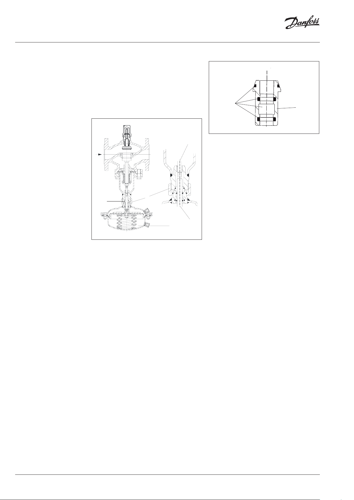
9 Replacement of Valve,
Actuator, Trims
9.2 Replacement of Trim Valve VFQ 21
The trim can be replaced by qualified personnel
up to DN 125. From DN 150 replacement should
be carried out by the Danfoss service personnel.
Removing the trim:
Valves DN 100–125
4
1. Dismount actuator 1
(see section 9.1).
2. Unscrew hexagon head cap screw 2.
3. Remove bonnet 3.
4. Take out trim 4.
Prior to installation:
Clean sealing surfaces 5 and socket 6, grease
sealing surfaces with antiseize graphite
petroleum.
Installing the trim:
Mounitng is carried out in reverse order.
Torque hexagon head cap screws 2:
DN Torque Wrench
100 -125 180 Nm SW 30
VI.JA.H3.5B
© Danfoss | 2016.05 | 19
Page 20

Instructions PCVPQ
2
9 Replacement of Valve,
Actuator, Trims
9.3 Dismounting, Mounting
Actuator AVP, AVP-F
1
Dismounting
1. Dismount impulse tubes.
2. Loosen union nut 1.
3. Remove actuator.
Mounting
1. Place actuator at the valve and align, observe
position of the impulse tube connections.
2. Screw on union nut 1 and tighten,
torque 100 Nm.
9.4 Replacement of Trim Valve AVP, AVP-F
AVP DN 25
2
AVP DN 40
Dismounting
1. Unscrew actuator (see above).
2. Unscrew trim 2.
DN 25: with pipe tongs, wrap gum strips
around the trim DN 40: with wrench SW 55
3. Pull out trim.
Mounting
Mounting is carried out in reverse order. Only
tighten with low torque, sealing is made with O
rings.
20 | © Danfoss | 2016.05
VI.JA.H3.5B
Page 21

Instructions PCVPQ
Inhaltsverzeichnis 1 Sicherheitshinweise ......................................22
2 Bestimmungsgemäße Verwendung .....22
3 Beschreibung ....................................................23
3.1 Auf bau ...................................................................23
3.2 Wirkungsweise ...................................................23
4 Technische Daten ............................................23
5 Lieferumfang ....................................................24
6 Montage ..............................................................25
6.1 Vor der Montage beachten ............................25
6.2 Einbaulage, Einbauort .....................................25
6.3 Beim Einbau beachten .....................................25
6.4 Einbau Steuerleitung ........................................25
6.5 Isolierung ..............................................................25
6.6 Einbauschema.....................................................26
6.7 Montagezeichnungen, Abmessungen ......27
7 Inbetriebnahme...............................................29
7.1 Erforderliche(r) statischer Druck,
Druckdifferenz ....................................................29
7.2 Dichtheitsprüfung / Druckprüfung ............29
7.3 Füllung der Anlage ............................................29
7.4 Inbetriebnahme .................................................29
7.5 Ausserbetriebnahme ........................................29
7.6 Volumenstromeinstellung .............................30
7.7 Einstellkennlinien ..............................................31
7.8 Differenzdruckeinstellung .............................33
7.9 Plombierung ........................................................33
7.10 Einstellung Drosselventil ................................33
7.11 Funktionsprüfung ............................................ 34
8 Störungshinweise ...........................................35
9 Austausch von Ventil, Antrieb,
Innengarnituren ..............................................36
9.1 Demontage,
Montage Antrieb Stellgerät ...........................36
VI.JA.H3.5B
9.2 Austausch der Innengarnitur
Ventil VFQ 21 .......................................................38
9.3 Demontage, Montage Antrieb
AVP, AVP-F.............................................................39
9.4 Austausch der Innengarnitur
Ventil AVP, AVP-F ................................................39
© Danfoss | 2016.05 | 21
Page 22
Instructions PCVPQ
1 Sicherheitshinweise
Montage, Inbetriebnahme und
Wartungsarbeiten dürfen nur von sachkundigen
und autorisierten Personen durchgeführt
werden.
Vor Montage und Wartungsarbeiten am Regler
die Anlage:
drucklos machen,
abkühlen,
entleeren und
reinigen.
Die Vorgaben des Anlagenherstellers und
Anlagenbetreibers sind zu beachten.
MAINTENANCE
FREE
Um Verletzungen an Personen
und Schäden am Gerät zu
vermeiden, ist diese Anleitung
vor der Montage unbedingt zu
beachten.
2 Bestimmungsgemäße
Verwendung
Der Regler dient der Volumenstrombegrenzung
und Differenzdruckregelung von Wasser für
Heizung, Fernwärmeheizung und Kühlsysteme.
Die zulässigen Mediumstemperaturen sind je
nach Ausführung 5 - 150 °C, 5 - 200 °C.
Die technischen Daten auf den Typenschildern
sind für die Verwendung maßgebend.
22 | © Danfoss | 2016.05
VI.JA.H3.5B
Page 23
Instructions PCVPQ
P
(Diff
3 Beschreibung 3.1 Aufbau
ilotregler AVP
erenzdruck)
Drosselventil
nur bei DN150-250
3.2 Wirkungsweise
Die Regeleinheit besteht aus dem in der
Hauptleitung eingebauten Stellgerät PCV-VFQ21
und dem im Bypass als Pilotregler angeordneten
Differenzdruckreglern AVP und AVP-F. In der
Bypassleitung ist vor den Pilotreglern ein
Drosselement eingebaut.
Der Regler hält den Differenzdruck über der
Anlagestrecke konstant und er begrenzt den
Volumenstrom entsprechend den eingestellten
Sollwerten.
Das Stellventil und die Pilotventile sind
druckentlastet.
Die Sollwerteinstellung des Differenzdruckes
erfolgt über die Vorspannung der Sollwertfeder
des Pilotreglers AVP. Der Sollwert für die
Volumenstrombegrenzung wird an der
Einstelldrossel des Stellgerätes eingestellt.
Das Stellgerät in der Hauptleitung ist drucklos
geschlossen. Die Pilotregler in der Bypassleitung
sind drucklos geöffnet.
Pilotregler AVP-F
(Durchfluss)
Einstelldrossel
Drosselelement DE
Stellgerät PCV-VFQ 21
Drosselventil
Differenzdruckregelung
Bei geringen Volumenströmen bleibt das Ventil
in der Hauptleitung durch die Druckfeder
im Antrieb des Stellgerätes geschlossen. Die
Differenzdruckregelung erfolgt ausschließlich
über das Pilotventil.
Erhöht sich der Volumenstrom in der
Bypassleitung, so sinkt der Druck im
Drosselelement (Venturidüse).
Dieser abgesenkte Druck wirkt über eine
Steuerleitung auf die Unterkammer des Antriebs
des Stellgerätes. Das Hauptventil wird dadurch
stoßfrei und stetig geöffnet. Reduziert sich
der Volumenstrom, so steigt der Druck im
Drosselelement an und das Hauptventil schließt.
Diese Folgeschaltung gewährleistet eine
schwingungsfreie Betriebsweise und eine
geringe Regelabweichung über einen großen
Stellbereich.
Volumenstrombegrenzung
Erreicht der Volumenstrom den eingestellten
Sollwert, so steigt der Differenzdruck an der
Einstelldrossel an. Dieser Differenzdruck wirkt
über die Steuerleitungen auf den Antrieb
AVP-F und das Ventil AVP-F schließt. In Folge
drosselt auch das Ventil des Stellgerätes und der
Volumenstrom wird begrenzt.
4 Technische Daten Technische Daten siehe Typenschilder und
Datenblatt PCV.
VI.JA.H3.5B
© Danfoss | 2016.05 | 23
Page 24
Instructions PCVPQ
5 Lieferumfang
DN 100-125
Bausatz Stellgerät PCV-VFQ 21 Pilotregler DN 25
AVP
DN 25
Drosselelement
Cu-Rohr Ø 6 × 1 × 1500 mm
Cu-Rohr Ø 10 x 1 × 3000 mm
AVP- F
DN 150-250
Bausatz Stellgerät PCV-VFQ 21 Pilotregler DN 40
AVP
DN 40
Drosselelement
Cu-Rohr Ø 6 × 1 × 1500 mm
Cu-Rohr Ø 10 × 1 × 3000 mm
AVP- F
24 | © Danfoss | 2016.05
VI.JA.H3.5B
Page 25

Instructions PCVPQ
6 Montage 6.1 Vor der Montage beachten
Anlage vor der Montage
drucklos machen!
Achtung!
• Rohrleitungssystem reinigen
• Schmutzfänger vor dem Regler einbauen
• Absperrarmaturen vor und nach dem Regler
einbauen
6.2 Einbaulage, Einbauort
• Der Einbau ist nur in waagrechte
Rohrleitung mit nach unten hängenden
Antrieben zulässig.
• Der Regler kann im Vorlauf oder Rücklauf
der Anlage eingebaut werden 6.3 Beim
Einbau beachten
• Durchflussrichtung beachten
• Ausführung mit Anschweißenden
6.3 Beim Einbau beachten
6.4 Einbau Steuerleitung
Siehe Einbauschema Abschnitt 6.6
Bei den CU-Leitungen Ø 10 × 1 beidseitig
Einsteckhülsen 1 einfügen.
1
Richtige Lage der Schneidringe 2 beachten
2
• Durchflussrichtung beachten
• Ausführung mit Anschweißenden
nur Heften
Schweißen
nicht
Schweißen
• Belastung der Ventilgehäuse und des
Drosselelementes durch die Rohrleitungen
sind nicht zulässig.
6.5 Isolierung
Bei Isoliermaßnahmen dürfen die
Membranantriebe nicht isoliert werden.
VI.JA.H3.5B
© Danfoss | 2016.05 | 25
Page 26

Instructions PCVPQ
r
Stellgerät PCV - VFQ 21
Steuerleitungen bei Montage verlegen
r
Pilotregler AVP-FPilotregler AVP-F
6 Montage
6.6 Einbauschema
Stellgerät PCV - VFQ 21
Einbau im Rücklauf
Drosselventil
Drosselelement
Drosselventil
(nur bei DN 150 - 250)
Hilfsgesteuerter Regle
PCVPQ
Einbau im Vorlauf
Pilotregler AVP
Drosselventil
Drosselelement
Drosselventil
(nur bei DN 150 - 250)
Hilfsgesteuerter Regle
PCVPQ
Pilotregler AVP
26 | © Danfoss | 2016.05
VI.JA.H3.5B
Page 27

Instructions PCVPQ
CU-Rohr Ø 6 × 1
DN 25: Rohr Ø 33,7 × 3,2
Werkstoff:
(kein Lieferbestandteil)
6 Montage
6.7 Montagezeichnung, Abmessungen
Bei Montage verlegen.
zum Rücklauf
zum Vorlauf
Steuerleitungen wegen
Verschmutzung seitlich
anbringen
Cu - Rohr
Ø 10 × 1
Bei Montage verlegen.
DN 100-125
ST 35.8
Pilotregler AVP
Pilotregler AVP-F
DN 25 SW 50
Drosselelement
VI.JA.H3.5B
© Danfoss | 2016.05 | 27
Page 28

Instructions PCVPQ
CU-Rohr Ø 6 × 1
anbringen
DN 40: Rohr
Werkstoff:
(kein Lieferbestandteil)
zum Rücklauf
zum Vorlauf
Steuerleitungen wegen
Verschmutzung seitlich
Bei Montage verlegen.
Cu - Rohr
Ø 10 × 1
Bei Montage verlegen.
ST 35.8
DN 150-250
Abmessungen
Ø 48.3 x 3.2
Nennweite DN 100 125 150 200 250
L1
350 400 480 600 730
H1 530 530 619 647 697
H2 - 245 300 325
D2 263 380
mm
D1 150 250 320 385 500
B 200 210 310 336 412
A ≥ 290 320 350 410
28 | © Danfoss | 2016.05
VI.JA.H3.5B
Page 29

Instructions PCVPQ
p2 p1
5
4
3
867
7 Inbetriebnahme
7.1 E rforderliche(r) statischer Druck,
Druckdifferenz
Für die Funktion ist eine Mindestdruckdifferenz
erforderlich: p1 - p2 ≥ 0,5 bar
Der statische Druck p1 vor dem Regler darf
1, 5 bar (Überdruck) nicht unterschreiten.
Nichtbeachtung kann zu Kavitation und Schäden
im Drosselement 1 führen.
1
7.2 Dichtheits-, Druckprüfung
Um unzulässig hohe Drücke
an den Membranantrieben
zu vermeiden muß vor
Druckprüfungen folgendes
beachtet werden:
Antrieb Stellgerät:
Der zulässige Betriebsüberdruck im Antrieb 2
beträgt 25 bar 1). Bei höherem Prüfdruck müssen:
• Die Steuerleitungen 3 am Antrieb entfernt
und die Anschlüsse mit einem Stopfen
verschlossen werden.
• Vor einer Dichtheitsprüfung bzw.
Druckprüfung nach Abschnitt 7.3 vorgehen
7.3 Füllung der Anlage
Hinweis:
Der Stellgerät 4 ist drucklos geschlossen und öffnet
erst bei definiertem Durchfluss im Bypass.
Die Pilotregler 5 sind drucklos geöffnet.
Vorgehensweise
1. Eventuell in den Steuerleitungen vorhandene
Absperrventile 6 öffnen.
2. Armaturen 7 in der Anlage öffnen.
3. Die Absperrarmaturen im Vorlauf 8 und im
Rücklauf 9 langsam öffnen.
9
7.4 Inbetriebnahme
Bei der Inbetriebnahme der gefüllten Anlage
ist die gleiche Reihenfolge beim Öffnen
der Armaturen zu beachten wie unter 7.3
beschrieben.
7.5 Ausserbetriebnahme
Bei der Ausserbetriebnahme zuerst die
Absperrarmaturen im Vorlauf und dann im
Rücklauf schließen.
VI.JA.H3.5B
2
1)
Voraussetzung: gleicher Druck auf beiden Seiten der
Membrane. B ei einseitiger Druckbe lastung ist in der
(+)-Membrankammer ei n max. Überdruck gege nüber der
(-)-Membrankam mer von 1 bar zulässig.
© Danfoss | 2016.05 | 29
Page 30

Instructions PCVPQ
erforderlicher
Volumenstrom
Umdrehungen Einstelldrossel
ablesen
7 Inbetriebnahme
7.6 Volumenstromeinstellung
Die Einstellung des Sollwertes für die
Volumenstrombegrenzung kann mit Hilfe von
Einstellkennlinien (s. Abschnitt 7.7) oder mittels
eines Wärmezählers erfolgen (siehe Seite 13).
Einstellungen mit Einstellkennlinien
Die Einstellung bei außer Betrieb genommener
Anlage durchführen.
Vorgehensweise
1. Die Abdeckhaube 1 abschrauben.
2
2. Die Kontermutter 2 lösen.
4. Die Einstelldrossel um diese Anzahl
Umdrehungen nach links drehen.
5. Über ein Volumenstrommeßgerät kann der
eingestellte Volumenstrom überprüft werden,
ggf. die Einstellung nachjustieren.
Auf ausreichenden Differenzdruck in der
Anlage achten.
6. Die Kontermutter anziehen. Die Stellung der
Einstelldrossel hierbei nicht verändern.
3
2. Die Einstelldrossel 3 bis zum Anschlag
eindrehen.
3
3. Diagramm auswählen, (siehe Abschnitt 7.7
Einstellkennlinien)
Wirkdruck Δpb beachten: 0,2 oder 0,5 bar
siehe Typenschild auf dem Antrieb AVP-F
7. Die Hutmutter 1 aufschrauben.
8. Die Hutmutter kann plombiert werden.
30 | © Danfoss | 2016.05
Die Volumenstromeinstellung ist abgeschlossen,
jetzt die Einstellung des Differenzdruckes
durchführen, siehe Abschnitt 7.8.
VI.JA.H3.5B
Page 31

Instructions PCVPQ
DN 100kvs 125/DN 125kvs 160/DN 150kvs 320
14
Umdrehungen Einstelldrossel
Volumenstrom (m
3
/h)
DN 100kvs 125/DN 125kvs 160/DN 150kvs 320
14
Volumenstrom (m
3
/h)
DN 200kvs 450/DN 250kvs 630
geforderte Volumenstrom
DN 200kvs 450/DN 250kvs 630
89
Umdrehungen Einstelldrossel
Volumenstrom (m
3
/h)
7 Inbetriebnahme
140
120
100
7.7 Einstellkennlinien
p
=0,2
b
DN150
80
60
40
DN100/125
20
0
0123456789 10 11 12 13
220
200
p
=0,5
b
180
160
140
120
100
80
60
40
20
0
0123456789 10 11 12 13
DN150
DN100/125
Umdrehungen Einstelldrossel
200
180
160
140
/h)
3
120
100
Volumenstrom (m
begrenzung 100 m³/h
DN 250
DN 200
80
60
40
20
0
01234567 8910
p
=0,2
b
Umdrehungen Einstelldrossel
Beispiel
Ventil DN 200
erforderliche
Umdrehungen
Einstelldrossel: 4
260
240
220
200
180
160
140
120
100
80
60
40
20
0
DN 250
DN 200
p
=0,5
b
012345 67
VI.JA.H3.5B
© Danfoss | 2016.05 | 31
Page 32

Instructions PCVPQ
P2
2
3
7 Inbetriebnahme
Einstellungen mit Volumenstrommessgerät
In diesem Fall ist es sinnvoll zuerst den
Differenzdruck (siehe Abschnitt 7.8) einzustellen.
Ein zu niedriger Differenzdruck kann dazu
führen, dass der erforderliche Volumenstrom
nicht erreicht wird.
Vorgehensweise
1. Vor der Volumenstromeinstellung
Inbetriebnahme der Anlage nach Abschnitt
7.4 durchführen.
2. Absperrarmaturen 1 und Regelarmaturen
2 müssen ganz geöffnet sein, so dass keine
Volumenstrombegrenzung über eine Armatur
erfolgt.
Die Einstellung kann auch über einen Bypass
3 erfolgen.
P1
1
5. Einstellung der Volumenstrombegrenzung
durch drehen der Einstelldrossel 6:
Rechtsdrehen 7: Volumenstrom reduzieren
7
6
Linksdrehen 8: Volumenstrom erhöhen
8
PCVPQ
3. Die Abdeckhaube 4 abschrauben.
4
4. Die Kontermutter 5 lösen.
6. Die Volumenstromanzeige beachten.
7. Nach der Einstellung. Die Kontermutter
anziehen. Die Stellung der Einstelldrossel
hierbei nicht verändern.
8. Die Hutmutter aufschrauben.
9. Die Hutmutter klann plombiert werden.
5
32 | © Danfoss | 2016.05
Die Volumenstromeinstellung ist abgeschlossen.
VI.JA.H3.5B
Page 33

Instructions PCVPQ
P1
4
max
5
n
1
7 Inbetriebnahme
7.8 Differenzdruckeinstellung
Der Sollwert des Differenzdrucks ist an
dem Pilotregler AVP 1 einzustellen. Der
Sollwertbereich ist auf dem Typschild des
Antriebes angegeben.
1
Vorgehensweise
1. Vor der Differenzdruckeinstellung
Inbetriebnahme der Anlage nach Abschnitt
7.4 durchführen. Die Einstellung des
Differenzdruckes kann auch erfolgen, wenn
ein Bypass 2 geöffnet ist.
2. Den Volumenstrom an einer Armatur, über
welche der Differenzdruck zu regeln ist,
einstellen.
Einstellung z.B. an der Armatur 3 oder 4 oder
über einen Bypass 2 auf ca. 50 % des max.
Volumenstroms 5.
4. Die Druckanzeigen sind zu beachten.
5. Nach der Differenzdruckeinstellung ist bei
offener Anlage zu überprüfen, ob der max.
Volumenstrom erreicht wird. ggf. ist der
Differenzdruck zu erhöhen.
7.9 Plombierung
Die Sollwertsteller können plombiert werden.
7.10 Einstellung Drosselventil
Anzahl der Drosselventile:
DN100, 125: 1
DN150-250: 2 x
• Die Abdeckhaube 1 abschrauben.
3
Linksdrehen
Dämpfung
reduzieren
SW 5
Rechtsdrehe
Dämpfung
erhöhen
9
PCVPQ
2
P2
p
0 50% V
3. Rechtsdrehung:Sollwerterhöhen
• Standardeinstellung:
Die Ventilspindel durch Rechtsdrehung
mit Sechskantschlüssel SW5 bis zum
Anschlag eindrehen. Dann Ventilspindel
durch Linksdrehung ca. 10 Umdrehungen
herausschrauben.
• Erhöhung der Dämpfung z. B. erforderlich bei
Druckschwingungen. Die Ventilspindel durch
Rechtsdrehung hineinschrauben.
• Reduzierung der Dämpfung z.B. bei zu
träger Regelung. Die Ventilspindel durch
Linksdrehung herausschrauben.
Linksdrehung: Sollwert reduzieren
VI.JA.H3.5B
© Danfoss | 2016.05 | 33
Page 34

Instructions PCVPQ
7 Inbetriebnahme
7.11 Funktionsprüfung
Differenzdruck
Durch Öffnen und Schließen einer Armatur
in der zu regelnden Anlagenstrecke ist der
Differenzdruck über die Druckanzeigen zu
überprüfen.
Schwingt der zu regelnde Differenzdruck, so
sind die Drosselventile etwas zu schließen (s.
Abschnitt 7.9).
Bei Über- oder Unterschreitung den
Differenzdruck nach Abschnitt 7.7 nachstellen.
Volumenstrom
Bei vollständig geöffneter Anlage darf der
eingestellte Volumenstrom nicht überschritten
werden.
Bei Über- oder Unterschreitung die Einstellung
nach Abschnitt 7.5 überprüfen.
34 | © Danfoss | 2016.05
VI.JA.H3.5B
Page 35

Instructions PCVPQ
8 Störungshinweise
Störung Mögliche Ursache Maßnahme
Drosselventile zu weit geöffnet Drosselventil etwas schließen siehe Abschnitt 7.10
1. Steuerleitungsanschlüsse an den Antrieben ca. 1 Umdrehung
Regler hält den
Volumenstrom bzw.
Differenzdruck nicht
konstant
Differenzdruck zu hoch
Volumenstrom zu
niedrig
1)
Austausch de r Innengarnitur bis DN 125 ist durch sachku ndige Personen möglic h. Ab DN 150 sollte der
Austausch durch de n Danfoss-Kundendienst e rfolgen.
Luft in den Antrieben
Steuerleitungen bzw.
Steuerleitungsanschlüsse verschmutzt oder verstopft
Pilotventil AVP, AVP-F schließt nicht:
Ventilsitz bz w. Kegel verschmutzt oder beschädigt
Stellventil VFQ 2 schließt nicht:
Ventilsitz bz w. Kegel verschmutzt oder beschädigt
Rollmembrane im Antrieb AVP, AVP-F (Pilotregler) defekt, d. h. Ventil
AVP schließt nicht
Ventilkegel des Pilotventils AVP öffnet nicht:
Ventilsitz bz w. Kegel verschmutzt oder beschädigt, Innengarnitur
verschmutzt
Ventilkegel des Stellventils VFQ 21 öffnet nicht:
Ventilsitz bz w. Kegel verschmutzt oder beschädigt, Innengarnitur
verschmutzt
Rollmembrane im Antrieb des Stellgerätes defekt, d. h. Ventil VFQ 21
öffnet nicht
lösen
2. Entlüften, Achtung Heisswaser!
(Steuerleitung bewegen bis Medium austritt)
3. Steuerleitungsanschlüsse wieder anziehen
1. Steuerleitungen demontieren
2. Steuerleitungen und Anschlüsse reinigen und Durchgang
überprüfen
1. Steuerleitungen abbauen
2. Antrieb und Innengarnitur demontieren Vorgehensweise siehe
Abschnitt 9.4
3. Sitz und Kegel reinigen
4. Bei Beschädigung Innengarnitur bzw. Ventil austauschen
1. Steuerleitungen abbauen
2. Antrieb und Innengarnitur demontieren 1)
Vorgehensweise siehe Abschnitt 9.2
3. Sitz und Kegel reinigen
4. Bei Beschädigung Innengarnitur bzw. Ventil austauschen
1. Steuerleitungen abbauen
2. Antrieb austauschen, siehe Abschnitt 9.3
1. Steuerleitungen abbauen
2. Antrieb und Innengarnitur demontieren Vorgehensweise siehe
Abschnitt 9.4
3. Sitz und Kegel reinigen
4. Bei Beschädigung Innengarnitur bzw. Ventil austauschen
1. Steuerleitungen abbauen
2. Antrieb und Innengarnitur demontieren 1)
Vorgehensweise siehe Abschnitt 9.1 und 9.2
3. Sitz und Kegel reinigen
4. Bei Beschädigung Innengarnitur bzw. Ventil austauschen
1. Steuerleitungen abbauen
2. Überwur fmutter SW 46 lösen und Antrieb abnehmen siehe auch
Abschnitt 9.1
3. Antrieb austauschen
VI.JA.H3.5B
© Danfoss | 2016.05 | 35
Page 36
Instructions PCVPQ
fetten
s
9 Austausch von
Ventil, Antrieb,
Innengarnituren
9.1 Demontage, Montage Antrieb Stellgerät
Hinweis:
Die Federn 1 im Antrieb sind vorgespannt.
Deshalb muss der Antrieb zur Demontage,
Montage hochgedrückt werden. Hierzu ist eine
2. Person erforderlich.
Stellgerät DN 100–125
3
SW 46
5
2
1
4
Vor der Montage Konus 5 überprüfen
5
Konu
1. Konus vor der Montage reinigen
2. O-Ringe auf Beschädigung überprüfen, bei
Beschädigung Konus austauschen (siehe
Ersatzteile)
3. Konus fetten mit HochleistungsArmaturenfett: z. B. BARRIERTA L55/3 HV
Montage
1. Antrieb am Ventil ansetzen und hochdrücken
2. Überwurfmutter 2 aufschrauben
3. Antrieb ausrichten, Position der
Steuerleitungsanschlüsse beachten
4. Überwurfmutter 1 anziehen, max.
Anzugsmoment 100 Nm
Ventilstange 3 und die Stange des Antriebs 4
sind nicht miteinander verschraubt.
Demontage
1. Steuerleitungen demontieren
2. Antrieb unten abstützen oder durch 2. Person
gegenhalten, da Federn 1 vorgespannt sind
3. Überwurfmutter 2 lösen
4. Antrieb abnehmen
36 | © Danfoss | 2016.05
VI.JA.H3.5B
Page 37

Instructions PCVPQ
9 Austausch von
Ventil, Antrieb,
Innengarnituren
Stellgerät DN 150–250
3
SW 46
1
4
Antrieb
nach links
drehen
die Stange des Antriebs 4 ist in die Ventilstange 3
eingeschraubt
Demontage
1. Steuerleitungen demontieren
2. Überwurfmutter 1 ganz lösen
Antrieb bleibt an der eingeschraubten
tange 4 hängen
Der Antrieb wiegt ca. 20
kg, zusätzlich ist internes
Federpaket vorgespannt. Vor
dem Herausschrauben gegen
herunterfallen sichern.
3. Durch drehen des Antriebs nach links die
Stange des Antriebs 4 aus der Ventilstange 3
herausschrauben
Montage
1. Antrieb am Ventil ansetzen und
hochdrücken um Federpaket im Antrieb
zusammenzudrücken (2. Person erforderlich)
2. Antrieb vorsichtig nach rechts drehen.
Dadurch die Stange des Antriebes in die
Ventilstange vorsichtig bis zum Anschlag
eindrehen.
danach unbedingt den
Antrieb um ca. 1 Umdrehung
zurückdrehen (nach links)
3. Antrieb ausrichten, Position der
Steuerleitungsanschlüsse beachten
4. Überwurfmutter 1 anziehen, Anzugsmoment
100 Nm SW
VI.JA.H3.5B
© Danfoss | 2016.05 | 37
Page 38

Instructions PCVPQ
2
3
1
5
6
9 Austausch von
Ventil, Antrieb,
Innengarnituren
9.2 Austausch der Innengarnitur
Ventil VFQ 21
Der Austausch der Innengarnitur bis DN 125 ist
durch sachkundige Personen möglich. Ab DN
150 sollte der Austausch durch den DanfossKundendienst erfolgen.
Innengarnitur ausbauen
Ventile DN 100–125
4
1. Antrieb 1 demontieren
(siehe Abschnitt 9.1)
2. Sechskantschrauben 2 herausschrauben
3. Ventilunterteil 3 abnehmen
4. Innengarnitur 4 herausnehmen
Vor dem Einbau
Dichtflächen 5 und Buchse 6 reinigen,
Dichtflächen mit Graphitfett fetten
Innengarnitur einbauen
Die Montage erfolgt in umgekehrter
Reihenfolge. Anzugsmoment der
Sechskantschrauben 2 :
38 | © Danfoss | 2016.05
DN Anzugsmoment Schlüsselweite
100 -125 180 Nm SW 30
VI.JA.H3.5B
Page 39

Instructions PCVPQ
2
9 Austausch von
Ventil, Antrieb,
Innengarnituren
9.3 Demontage, Montage Antrieb AVP, AVP-F
1
Demontage
1. Steuerleitungen demontieren
2. Überwurfmutter 1 lösen
3. Antrieb abnehmen
Montage
1. Antrieb am Ventil aufsetzen und ausrichten,
osition der Steuerleitungsanschlüsse
beachten
2. Überwurmutter 1 aufschrauben und
anziehen, Anzugsmoment 100 Nm
9.4 Austausch der Innengarnitur
Ventil AVP, AVP-F
AVP DN 25
2
Demontage
1. Antrieb abschrauben (siehe oben)
2. Innengarnitur 2 herausschrauben DN 25: mit
Rohrzange, Gummistreifen um Innengarnitur
wickeln DN 40: mit Schlüssel SW 55
3. Innengarnitur herausziehen
Montage
Die Montage erfolgt in umgekehrter
Reihenfolge. Nur mit niedrigem Anzugsmoment
anziehen, Abdichtung erfolgt mit O-Ringen.
VI.JA.H3.5B
© Danfoss | 2016.05 | 39
Page 40

Danf
already on order pro
All trademarks in this material are property of the respec
Instructions PCVPQ
oss can accept no responsibility for possible errors in catalogues, brochures and other printed material. Danfoss reserves the right to alter its products without notice. This also applies to products
vided that such alterations can be made without subsequential changes being necessary eady agreed.
40 | © Danfoss | DHS-SRMT/SI | 2016.05
tive companies. Danfoss and the Danfoss logotype are trademarks of Danfoss A/S. All rights reserved.
73696690/VI.JA.H3.5B
 Loading...