

Data sheet
Pilot-controlled differential pressure controller (PN 16, 25, 40)
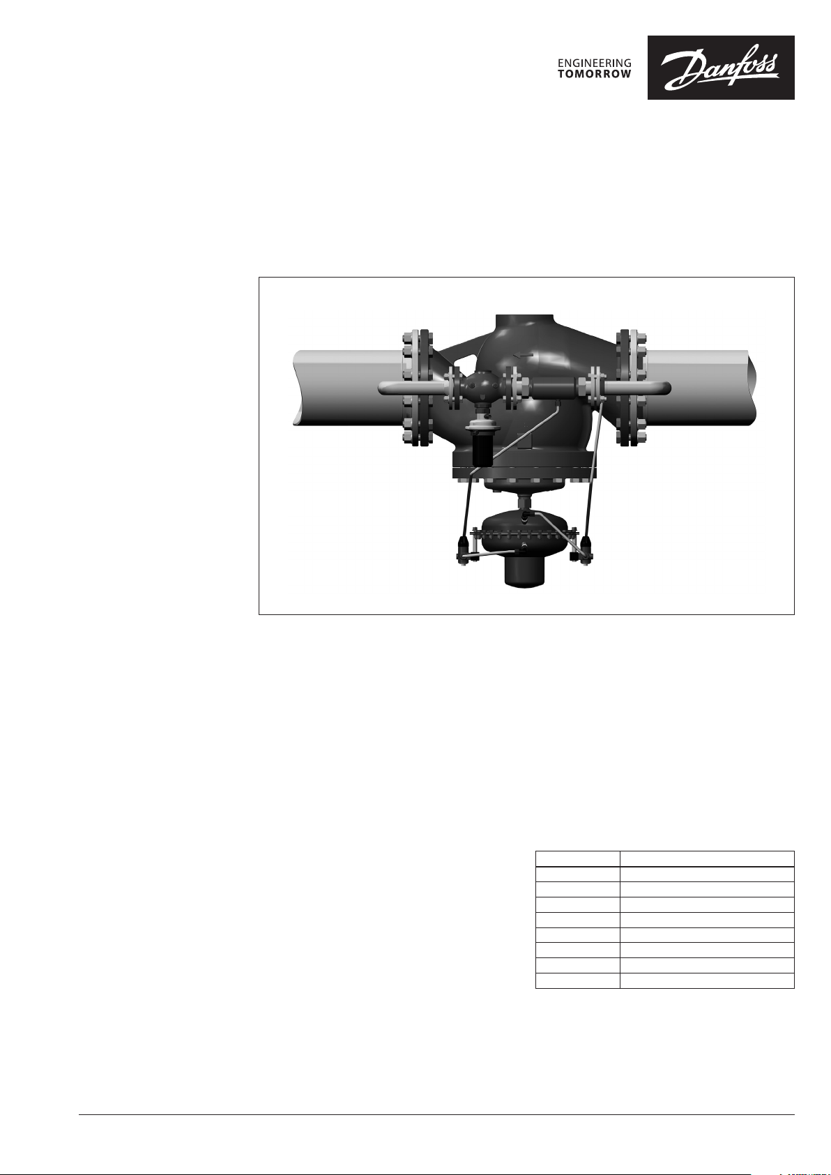
PCVP - flow and return mounting, adjustable setting
Description
Pilot-controlled differential pressure controller is
a self-acting differential pressure
controller primarily for use in district heating,
district cooling or in industrial systems as well. It
can be flow and return mounted in applications
with and without heat exchanger like large
substations and distribution stations.
The controller consist of main controller, installed
in main pipe, and pilot controller and with a
throttling element, both installed in bypass.
Setting is done on pilot controler.
Throttle valve data can be found on page 10.
Main data1) :
• DN 50-250
• kVS 32-630 m3/h
• PN 16, 25, 40
2)
3)
• Temperature:
- Circulation water/glycolic water up to 30%:
2 … 200°C
• Connections:
- Pilot controller:
ext. thread (weld-on tailpieces) or flange
- Main valve: flange
1)
for details see Technica l data and Ordering sections
2)
smaller DN on re quest
3)
PN 40 on special re quest
Features:
- Differential pressure controller
- Extremely high control ratio (see Tab.1) as a
result of low pilot controller min. flow rate
(kVS value) and high flow rate (kVS) of the main
valve
- Small overall dimensions comparing to
standard design (especially height)
- Higher valve capacities for DN 150-250
comparing to standard design
- High control stability
- Smooth operation differential pressure
controller
Tab. 1
DN Min. control rat io
50 100 : 1
65 140 : 1
80 220 : 1
100 300 : 1
125 400 : 1
150 400 : 1
200 550 : 1
250 750 : 1
© Danfoss | 2018.04 VD.JA.N3.02 | 1
Data sheet PCVP - Pilot-controlled differential pressure controller (PN 16, 25, 40)
Technical Data Main valve
Nominal diameter DN 50 65 80 100 125 15 0 200 250
kVS value m3/h 32 50 80 125 160 320 450 630
Cavitation factor z 0.5 0.5 0.45 0.4 0.35 0.3 0.2 0.2
2)
On request
3)
Stainless steel M . No. 1.4571
4)
EPDM
1)
Defined by pilot controller
Leakage acc. to standard IEC 534 ≤ 0.05% of k
Nominal pressure PN 16, 25, 40
Max. differential pressure
Min. differential pressure 0.5
PN 16
PN 25, 40 20
bar
16
Min. static pressure 1.5
Medium VF G 2(1) Circulation water/glycolic water up to 30%
Medium pH Min. 7, max. 10
Medium temperature
Connections
Weight
VFG 21 PN 16, 25, 40 2 … 150 °C
VFG 2 PN 16, 25, 40 2 … 200 °C
Main controller Flange
Pilot controller Ext. thread (weld- on tailpieces) or flange Flange
PN 16 /25
PN 40 30 32.5 60.5 69 141 253 333
kg 18
27. 5 30 58 68 115 185 323
Materials
PN 16 Grey cast iron EN-GJL-250 (GG-25)
Valve body
PN 25
Ductile cast iron EN-GJS -400-18-LT
(GGG-40.3)
PN 40 Cast steel EN-GP-240-GH (GS -C 25)
Valve seat Stainless steel M. No. 1.4021
Valve cone VF G 2(1) Stainless steel M. No. 1.4404
Sealing
Pressure relieve system Bellows
VFG 21 EPDM
VFG 2 Metal
3)
Main actuator
For main va lve DN 50 - 125 150 - 250
Actuator size cm
Max. operational pressure
Flow restrictor differential pressure p
Diff. pressure setting ranges
1)
Weight kg 11 24
Materials
Housing Stainless steel M. No. 1.0338
Control diaphragm EPDM
Impulse tube Stainless steel tube Ø10 × 0.8 mm
Nr. of throttle valves (mounted on impulse tubes) 1 2
2
250 630
25 16 , 25
1)
bar
b
0.2-1.0/0.3-2.0/1-5/3-12
Trottling element
For main va lve DN 50 - 125 150 - 250
Size of throttling element DN 25 40
Connections Welded end Flange
Max. operational pressure 25
Weight kg 3.2 6.6
Materials
Body material Red bronze, M. No. 2.1090
Impulse tube Stainless steel tube Ø10 × 0.8 mm
VS
15 12 10
2)
0.2/0.5
Cast steel EN-GP-240-GH
(GS-C 25)
2)
Stainless steel M. No.
1.4 313
Stainless steel M. No.
1.4021
Diaphragm4) (T
Bellows3) (T
max
max
150 °C )
300 °C)
2 | VD.JA.N3.02 © Danfoss | 2018.04
Data sheet PCVP - Pilot-controlled differential pressure controller (PN 16, 25, 40)
Ordering
Example 1:
Pilot-controlled differential pressure
controller; DN 100; kVS 125; PN 16;
setting range 0.2-1.0 bar; T
flange;
- 1× PCV-VFG 21 DN 100
Code No.: 0 03G157 3
- 1× AVP DN 25
Code No.: 0 03H 6319
- 1× Weld-on tailpieces DN 25
Code No.: 0 03H6910
- 1×
Mounting set for Impulse tube
Code No.: 0 03G159 9
1)
Contains accessories fo r remounting
the impulse tub e on the pilot controller
from internal co nnection (factory
delivered) to e xternal connectio n.
max
150 °C;
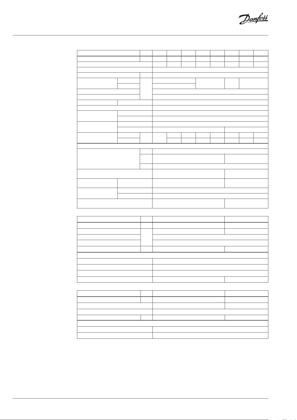
DN 50-125
PCV-VFG 21 - Main controller, throttling element, throttle valve, impulse tubes
DN 25
DN
(mm)
50 32
65 50 003G155 8
80 80 003G1559
100 125 003G1573
125 160 00 3G1574
50 32
65 50 003 G1568
80 80 003G15 69
100 125 0 03G152 3
125 160 003 G1524
Impulse tube
k
VS
(m3/h)
T
(°C)
max
PN Connection
150 16 Flange EN 1092-2 15
150 25 Flange EN 1092-2 15
Copper
Ø 6 × 1 × 3000 mm
Ø 10 × 1 × 1500 mm
Stainless steel Ø 10 × 0.8 × 1500 mm
Pilot controller AVP
DN
k
T
VS
max
(mm)
(m3/h)
PN Connection
(°C)
Cylindr. ext.
25 8.0 150 25
thread acc. to
DIN ISO 228/1
Weld-on tailpieces DN 25 003 H6910
Mounting set for impulse tube
1)
G 1¼ A
Δp setting range
(bar)
0. 2-1.0
0.3-2.0 003H6329
1-5
3-12
Δp
(bar)
max
Δp
(bar)
Code No.
003G1626
003G6707
max
Code No.
003 H6319
20
on request
003G1599
1) Contains accessories for remo unting
the impulse tub e on the pilot controller
from internal co nnection (factory
delivered) to e xternal connectio n.
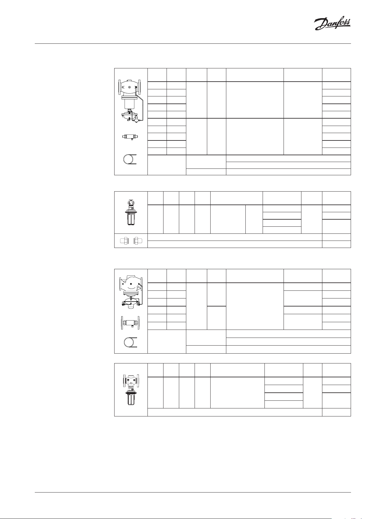
DN 150-250
PCV-VFG 21 - Main controller, throttling element, throttle valves, impulse tubes
DN 40
DN
(mm)
150 320
200 450
250 630 003 G1507
150 320
200 450
250 630 003 G1527
Impulse tube
k
(m3/h)
T
VS
(°C)
max
PN Connection
16
150
25
Copper
Ø 6 × 1 × 3000 mm
Ø 10 × 1 × 1500 mm
Stainless steel Ø 10 × 0.8 × 1500 mm
Flange EN 1092-2
AVP
DN
k
T
VS
max
(mm)
(m3/h)
PN Connection
(°C)
40 20 150 25 Flange EN 1092-2
Mounting set for Impulse tube
1)
Δp setting range
(bar)
0. 2-1.0
0.3-2.0 003H6379
1-5
3-12
Δp
(bar)
max
Code No.
12 00 3G1505
10
003G1506
12 003G15 25
(bar)
max
003G152 6
Code No.
10
Δp
003H6373
16
on request
003G1599
VD.JA.N3.02 | 3© Danfoss | 2018.04
Data sheet PCVP - Pilot-controlled differential pressure controller (PN 16, 25, 40)
Ordering (cont inuous)
Example 2:
Pilot-controlled differential pressure
controller; DN 150; kVS 320; PN 16;
setting range 0.2-1.0 bar; T
flange;
- 1× PCV-VFG 21 DN 150
Code No.: 003G15 05
- 1× AVP DN 40
Code No.: 0 03H6373
- 1×
Mounting set for impulse tube
Code No.: 0 03G159 9
1)
At temperature s above 150 °C only with
seal pots (see Accesso ries)
max
150 °C;
DN 150-250
PCV-VFG 2 - Main controller, throttling element, throtlle valves, seal pots, impulse tubes
DN
k
T
VS
max
(mm)
(m3/h)
PN Connection
(°C)
150 320
200 450
16
250 630
150 320
25
200 450
DN 40
3.0 l (2 ×)
250 630
150 320
250 630
Impulse tube
200
40
Copper Ø 10 × 1 × 1500 mm
Stainless steel Ø 10 × 0.8 × 1500 mm
Flange EN 1092-2
VFG 2 Valves (metallic sealing cone)
DN
(mm)
k
(m3/h)
T
VS
(°C)
max.
Connections
PN 16 PN 25 PN 40
40 20 150 2001)Flanges acc. to EN 1092-1 065B2392 065B2405 06 5B2415
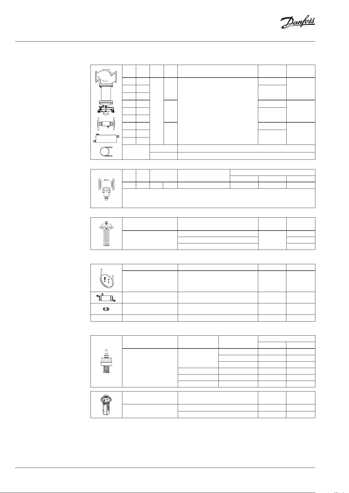
AFP / AFP-9 Actuators
Typ e
AFP
∆p setting range
(bar)
0.15 -1.5
0.1-0.7 00 3G1017
0.05-0.35 00 3G1018
Δp
(bar)
max
Code No.
12
10
on request
12
10
on request
12
10
on request200 450
Code No.
for DN Code No.
003 G1016
15-2 50
1)
Seal pot has to be us ed on impulse
tubes always w hen T
2)
Consist of a nipple , compression ring
and nut
3)
Impulse tube s on T>150 °C or PN> PN 16
≥ 150 °C
max
should be of stai nless steel
Accessories
Type designation Description Connections Code No.
Impulse tube set AF
Seal pot V1
Compression fitting
Throttle valve-PCV Regulating and shut-off device - 065Z1502
Service kits AVP
Type designation
Valve insert
Type designation
Actuator with adjustable
handle (AVP)
- 1× Copper tube Ø10 × 1 × 1500 mm
3)
- 1 × compression fitting for imp. tub e
connection to pipe (G ⁄)
- 003G1391
- 2 × socket
1)
2)
Capacit y 1 liter; with compression fittings
for imp. tube Ø10
For impulse tube Ø10 connections to
controller
DN
(mm)
k
VS
(m3/h)
- 003G1392
G ⁄ 003G1468
Code No.
AVP return AVP flow
1.6 003H6863 003H6871
15
2.5 003H6864 003H6872
4.0 003H6865 003H6873
20 6.3 003H6866 003 H6874
25 8 003H6867 003H6 875
32 / 40 / 50 12.5 / 20 / 25 003H6868 003H 6876
Δp setting range
(bar)
AVP return AVP flow
0. 2-1.0 003H6829 003H6834
0.3-2.0 003H6830 003H6835
4 | VD.JA.N3.02 © Danfoss | 2018.04

Data sheet PCVP - Pilot-controlled differential pressure controller (PN 16, 25, 40)
Ordering (cont inuous)
Function
Service kits AFP
Type designation
Valve insert
Stuffing cone (with EPDM O-rings) 003G1464
(mm)
100 125
125 160
150 280 065B2964 065B2966
250 400 065B2965 -
The pilot valve maintains the differential pressure
over selected part of system/application. By this
action also flow through a bypass changes and
therefore (-p) at the throttling element.
Pressure changes from inlet pipe (+p) and from
throttling element (-p) are being transferred
through the impulse tubes to the main actuator
chambers and act on control diaphragm
In case of small flow rates the main controller is
closed and control is taken by the pilot controller
only. With increasing the flow rate, a negative
pressure is built in the throttling element.
This partial vacuum acts on the main actuator
diaphragm and causes the main controller to
open.
DN
15 4.0 065B2796 065B2790
20 6.3 065B2797 065B2791
25 8
32 16
40 20
50 32
65 50
80 80
k
VS
(m3/h)
Code No.
for VFG 2 for VFG 21
065B2798 065B2792
065B2799 065B2793
065B2800 065B2794
065B2801 0 65B2795
Main valve
⊕ p
◯ p
−
Throttling
element
Throttle valve
Bypass
Pilot controller
Main controller
Main actuator
Installation positions
Both main and pilot controllers have to be
installed in horizontal pipes only, with a pressure
actuator oriented downwards.
VD.JA.N3.02 | 5© Danfoss | 2018.04

Data sheet PCVP - Pilot-controlled differential pressure controller (PN 16, 25, 40)
Installation positions
(cont inuous)
Installation in the return pipe T
Main controller
Trottling
element
Pilot controller
Installation in the supply pipe
Main controller
Trottling
element
Pilot controller
max
T
max
= 150 °C
= 200 °C
Pressure temperature
diagram
Working area is below P-T line
and it ends at T
for each valve
max
PN 25
PN 16
EN-GJS- 400
(GGG-40.3)
EN -GJL-2 50
(GG -25)
Maximum allowed operating pressure as a function of medium temperature (according to EN 1092-2)
PN 40
EN-GP-240-GH
(GS- C 25)
Maximum allowed operating pressure as a function of medium temperature (according to EN 1092-1)
6 | VD.JA.N3.02 © Danfoss | 2018.04

Data sheet PCVP - Pilot-controlled differential pressure controller (PN 16, 25, 40)
Dimensions Impulse tubes (pos.1, 2, 3) are part of the delivery.
Their shape depends on the controller type. In
case of high temperatures (T
have to be installed. For details see relevant
> 150) seal pots
max
Instructions.
T
150 DN 50-250
max
⑤
Location of conn ection
depends of con troller type
①
②
The components shown with dashed lines are
NOT part of the delivery. The pipes (pos. 5) must
be welded during mounting.
L
2
H
1
H
③
D
DN 50 65 80 10 0 125 15 0 200 250
L
H
1
H
2
D 263 263 263 263 263 380 380 380
230 290 310 350 400 480 600 730
390 42 5 425 530 530 619 647 697
mm
82 95 95 12 5 125 17 9 237 257
VD.JA.N3.02 | 7© Danfoss | 2018.04

Data sheet PCVP - Pilot-controlled differential pressure controller (PN 16, 25, 40)
Dimensions (cont inuous)
T
200 DN 150-250
max
Location of conn ection
depends of con troller type
⑤
④
①
②
L
2
H
1
H
③
DN 15 0 200 250
L
H
2
H
4
D 380 380 380
480 600 730
169 234 254
mm
916 1162 14 94
D
Impulse
tubes
①
②
③
④
T
max
(200 °C)
Cu Ø 6 × 1
SS Ø 10 × 0.8
Cu Ø 10 × 1
SS Ø 6 × 1
8 | VD.JA.N3.02 © Danfoss | 2018.04

Data sheet PCVP - Pilot-controlled differential pressure controller (PN 16, 25, 40)
Dimensions (cont inuous)
T
150 °C DN 50-125
max
T
150°C DN 150-250
max
①
160
244
ca. 1200
DN 50 65 80 10 0 12 5
A
mm
290 290 290 290 290
1
D
A
75
159
B
A
Pipes Pos. 1:
DN 25: Pipes Ø 33.7 × 2.6
DN 40: Pipes 48.3 × 3.2
min 300
①
290
DN 150 200 250
D
1
A 320 350 410
B 310 336 412
320 385 500
mm
200
ca. 1200
min 300
VD.JA.N3.02 | 9© Danfoss | 2018.04

Data sheet PCVP - Pilot-controlled differential pressure controller (PN 16, 25, 40)
6
20
(1 revolution of spindle equals to 1 mm stroke)
Flow [l/min]
Throttle valve
Flow diagram
Throttle valve is regulating and shut-off device,
which is / are installed on the impulse tubes
connected to main PCV actuator. Number of
used throttle valves can be seen in table for Main
actuator in Technical Data section.
Function of throttle valve is to control flow
speed through impulse tube and consequently
influence on PCV’s reaction time. Influence
on reaction time is not completly defined and
strongly depends on application conditions
and could significantly vary from application to
application.
In general:
- by opening of the valve (clockwise) PCV’s
reaction time increases
- by valve closing (counterclockwise) PCV’s
reaction time decreases
In case valve is completly closed it has function
as shut-off valve.
Throttle valve is delivered from factory in
completly open position.
Main data:
• DN 4
• used for Ø10 mm impulse tube
5
4
3
2
1
0
0 2 4 6 8 10 12 14 16 18
Stroke [mm] = no. of revolution
10 | VD.JA.N3.02 © Danfoss | 2018.04

Data sheet PCVP - Pilot-controlled differential pressure controller (PN 16, 25, 40)
VD.JA.N3.02 | 11© Danfoss | 2018.04

Data sheet PCVP - Pilot-controlled differential pressure controller (PN 16, 25, 40)
© Danfoss | DHS-SRMT/SI | 2018.0412 | VD.JA.N3.02
 Loading...