

Optyma™ Plus
OP-LPQM, OP-MPXM
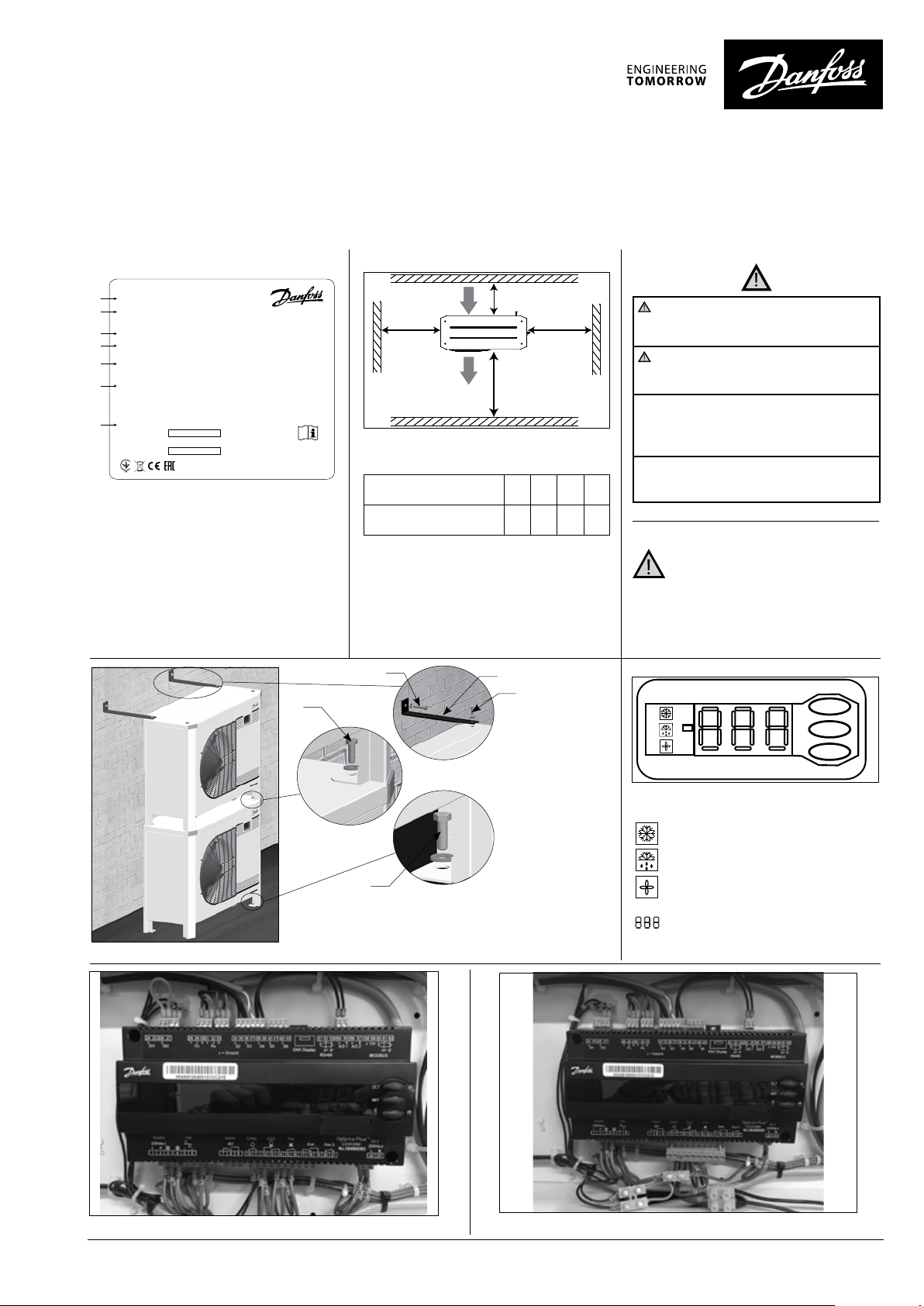
Name plate
A
OP-MPXM034MLP00G
114X4261
B
C
Application MBP
D
Refrigerant (1) R404A R507 R448A/R449A
R407A/R407F/R452A
E
M.W.P. HP (1) 28 bar
M.W.P. LP (1) 7 bar
F
Voltage 230 V ~ 1N ~ 50Hz
LRA 60 A MCC 19 A
OIL INSIDE POE 46
G
Serial No. 123456CG2816
EAN No.
xxxxxxxxxxxxxx
A: Model
B: Code number
C: Application, Protection
D: Refrigerant
E: Housing Service Pressure (Maximum
working pressure)
F: Supply voltage, Locked Rotor Ampere,
Maximum Current Consumption
G: Serial Number and bar code
MADE IN INDIA
IP 54
(2) R134a
R513A
(2) 23 bar
(2) 5 bar
Danfoss A/S, 6430 Nordborg, Denmark
Picture 1 : Minimum mounting distances
Q: Air in R: Air out
118UXXXXXX
(Code n° 114X34-- or 114X44--)
Unit
Housing 4
Q
W
ZY
R
X
The condensing unit must only be used for
its designed purpose(s) and within its scope of
application.
Under all circumstances, the EN378 (or
other applicable local safety regulation)
requirements must be fulfilled.
The condensing unit is delivered under nitrogen gas pressure (1 bar) and hence it cannot
be connected as it is; refer to the «installation»
section for further details.
The condensing unit must be handled with cau-
W
[mm]X [mm]Y [mm]Z [mm]
250 900 700 700
tion in the vertical position (maximum offset
from the vertical : 15°)
Installation and servicing of the condensing
units by qualified personnel only.
Follow these instructions and sound
refrigeration engineering practice relating to
installation, commissioning, maintenance and
service.
Picture 2 : Stacked mounting
V
T
U
U
V
T: Mounting brackets for stacked mounting (not supplied)
U: M8 bolts for stacked mounting (supplied)
V: Mounting bolts (not supplied)
Picture 3 : Electronic controller display
Compressor running
Crankcase heater on
Fan running
Temperature value for suction pressure.
Push lower button to switch to temperature value for condensing pressure
Picture 4 : Normal wiring Picture 5 : Temporary wiring
118A2221B - AN363632996019en-ZA0102 | 1© Danfoss | Climate Solutions | 2021.10
Instructions
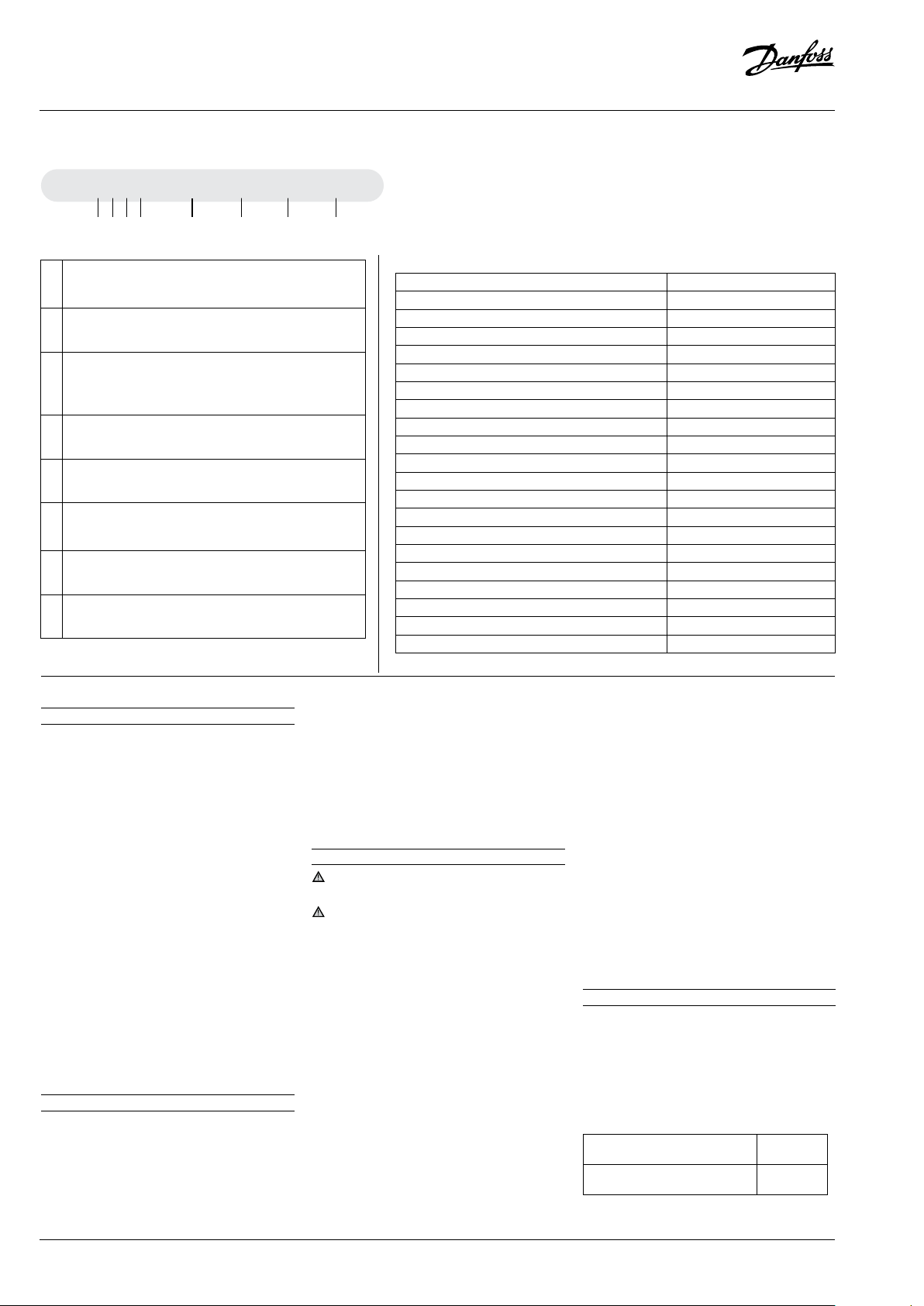
Designation system for the Optyma™ Plus range
OP - MPXM 034 ML P06 G
1 2 3 4 5 6 7 8
1 Application
M = MBP
L = LBP
2 Package
Condensing unit family: P = Optyma™ Plus
3 Refrigerant
Q = R452A, R404A/R507
X = R404A/R507, R134a, R407A, R407F, R448A, R513A
R449A,R452A
4 Condenser
M = Microchannel heat condenser
5 Swept volume
Displacement in cm
3:
Example 034 = 34 cm
3
6 Compressor platform
ML = Fixed speed scroll MLZ
LL = Fixed speed scroll LLZ
7 Version
P06: Optyma™ Plus with PRV
8 Voltage code
E = 400V/3-phase/50Hz compressor & 230V/1-phase fan
Version control
Optyma™ Plus (P06)
IP level IP54
Compressor technology Scroll/ Reciprocating
Control box (pre-wired E-panel) yes
Microchannel condenser yes
Fan speed controller* yes
Main switch (circuit breaker) yes
Supply monitoring relay Filter drier (flare connections) yes
Sight glass yes
Crankcase heater yes
HP/LP adjustable pressostat Electronic
Fail safe mini-pressostat Mechanical
Access door(s) yes
Acoustic insulation yes
Condensing unit electronic controller yes
Network connectivity yes
Stack mounting yes
Discharge gas thermostat yes
HP/LP Alarm yes
Pressure relief valve yes
* Inbuilt function within Condensing unit electronic controller
1 – Introduction
These instructions pertain to Optyma
™
Plus
condensing units OP-LPOM, & OP-MPXM used
for refrigeration systems. They provide necessary
information regarding safety and proper usage of
this product.
The condensing unit includes following:
• Microchannel heat exchanger
• Reciprocating or scroll compressor
• Receiver with stop valve
• Ball valves
• Sight glass
• High & low pressure switches
• Replaceable filter drier
• Electronic controller
• Main circuit breaker (Main switch with overload
protection)
• Fan and compressor capacitors
• Compressor contactor
• Robust weather proof housing
2 – Handling and storage
• It is recommended not to open the packaging
before the unit is at the final place for
installation.
• Handle the unit with care. The packaging
allows for the use of a forklift or pallet jack. Use
appropriate and safe lifting equipment..
• Store and transport the unit in an upright
position.
• Store the unit between -35°C and 50°C.
• Don’t expose the packaging to rain or corrosive
atmosphere.
• After unpacking, check that the unit is complete
and undamaged.
3 – Installation precautions
Never place the unit in a flammable
atmosphere.
Place the unit in such a way that it is not
blocking or hindering walking areas, doors,
windows or similar.
• Ensure adequate space around the unit for air
circulation and to open doors. Refer to picture
1 for minimal values of distance to walls.
• Avoid installing the unit in locations which are
daily exposed to direct sunshine for longer
periods.
• Avoid installing the unit in aggressive and
dusty environments.
• Ensure a foundation with horizontal surface
(less than 3° slope), strong and stable enough
to carry the entire unit weight and to eliminate
vibrations and interference.
• The unit ambient temperature may not exceed
50°C during off-cycle.
• Ensure that the power supply corresponds to
the unit characteristics (see nameplate).
• When installing units for HFC refrigerants,
use equipment specifically reserved for HFC
refrigerants which was never used for CFC or
HCFC refrigerants.
• Use clean and dehydrated refrigeration-grade
copper tubes and silver alloy brazing material.
• Use clean and dehydrated system components.
• The suction piping connected to the
compressor must be flexible in 3 dimensions
to dampen vibrations. Furthermore piping has
to be done in such a way that oil return for the
compressor is ensured and the risk of liquid
slug over in compressor is eliminated.
4 – Installation
• The installation in which the condensing unit is
installed must comply to pressure Equipment
Directive (PED) 2014/68/EU. The condensing unit
itself is not a ”unit” in the scope this directive.
• It is recommended to install the unit on rubber
grommets or vibration dampers (not supplied).
• It is possible to stack units on top of each other.
Unit
Housing 4
(Code no. 114X34-- or 114X44--)
Maximum
stacking
2
• When stacking, the topmost unit must be
2 | AN363632996019en-ZA0102 - 118A2221B
© Danfoss | Climate Solutions | 2021.10
Instructions
secured to the wall, as shown in picture 2.
• Slowly release the nitrogen holding charge
through the schrader port.
• Connect the unit to the system as soon as
possible to avoid oil contamination from
ambient moisture.
• Avoid material entering into the system while
cutting tubes. Never drill holes where burrs
cannot be removed.
• Braze with great care using state-of-the-art
technique and vent piping with nitrogen gas
flow.
• Connect the required safety and control
devices. When the schrader port is used for this,
remove the internal valve.
• It is recommended to insulate the suction pipe
up to the compressor inlet with 19 mm thick
insulation.
5 – Leak detection
Never pressurize the circuit with oxygen or dry
air. This could cause fire or explosion.
• Do not use dye for leak detection.
• Perform a leak detection test on the complete
system.
• The maximum test pressure is 31 bar.
• When a leak is discovered, repair the leak and
repeat the leak detection.
6 – Vacuum dehydration
• Never use the compressor to evacuate the
system.
• Connect a vacuum pump to both the LP & HP
sides.
• Pull down the system under a vacuum of 500
µm Hg (0.67 mbar) absolute.
• Do not use a megohmmeter nor apply power
to the compressor while it is under vacuum as
this may cause internal damage.
7 – Electrical connections
• Switch off and isolate the main power supply.
• Ensure that power supply can not be switched
on during installation.
• All electrical components must be selected as
per local standards and unit requirements.
• Refer to wiring diagram for electrical
connections details.
• Ensure that the power supply corresponds
to the unit characteristics and that the power
supply is stable (nominal voltage ±10% and
nominal frequency ±2,5 Hz).
• Dimension the power supply cables according
to unit data for voltage and current.
• Protect the power supply and ensure correct
earthing.
• Make the power supply according to local
standards and legal requirements.
• The unit is equipped with an electronic
controller. Refer to Manual 118U3808 for details.
• The unit is equipped with a main switch with
overload protection. The overload protection is
factory preset but it is recommended to check
the value before taking the unit in operation.
The value for the overload protection can be
found in the wiring diagram in the front door of
the unit.
• The unit is equipped with high and low
pressure switches, which directly cut the power
supply to the compressor in case of activation.
Parameters for high and low pressure cut outs
are preset in the controller, adapted to the
compressor installed in the unit.
• P05 models are also equipped with phase
sequence relay to protect the unit against
phase loss/sequence/ asymmetry and under-/
over-voltage.
For units with a 3-phase scroll compressor (OPMPXMxxxxxxxxE), correct phase sequence for
compressor rotation direction shall be observed.
• Determine the phase sequence by using a
phase meter in order to establish the phase
orders of line phases L1, L2 and L3.
• Connect line phases L1, L2 and L3 to main
switch terminals T1, T2 and T3 respectively.
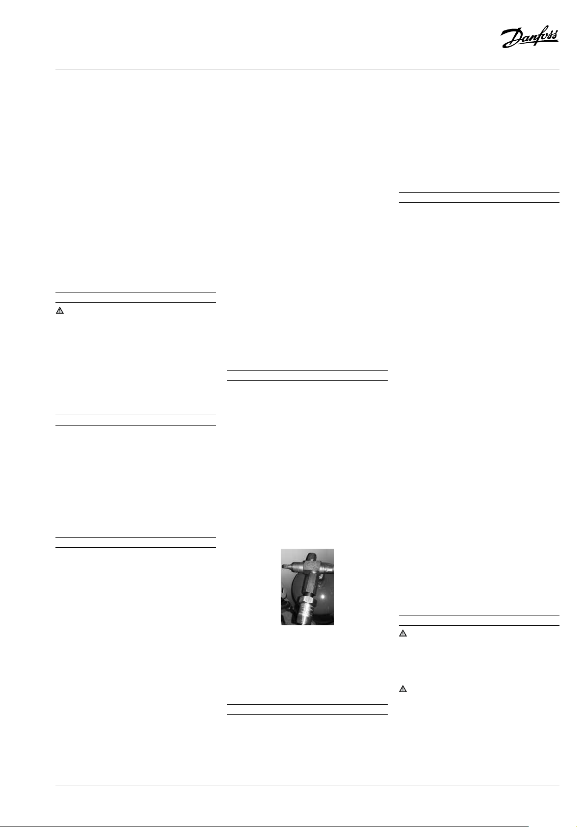
8 – Safety
Fusible Plug is not installed in unit, it is replaced
with adapter blanking plug.
Unit has liquid receiver with an Adapter Plug with
3/8” NPT connection. installer/end user can select
various options as mentioned in EN378-2 : 2016
Article § 6.2.2.3
• Optyma Plus fitted with atmospheric pressure
relief valve. Don’t connect any tube at end of the
pressure relief valve.
• Once the pressure relief valve opens, don’t use
dry air or oxygen to evacuate the refrigerants.
• Optyma Plus (P06 version only) factory fitted
with pressure relief valve at 33 bar setting.
• Once pressure relief valve opens, Danfoss
recommended to replace new pressure relief
valve.
• The unit/installation into which the condensing
unit is mounted/integrated, must be in
accordance with the PED.
• Beware of extremely hot and cold components.
• Beware of moving components. Power supply
should be disconnected while servicing.
9 – Filling the system
• Never start the compressor under vacuum.
Keep the compressor switched off.
• Use only the refrigerant for which the unit is
designed for.
• Fill the refrigerant in liquid phase into the
condenser or liquid receiver. Ensure a slow
charging of the system to 4 – 5 bar for R404A/
R448A/R449A/R407A/R407F/R452A and
approx. 2 bar for R134a and R513A.
• The remaining charge is done until the
installation has reached a level of stable
nominal condition during operation.
• Never leave the filling cylinder connected to
the circuit.
10 – Setting the electronic controller
• The unit is equipped with an electronic controller
which is factory programmed with parameters
for use with the actual unit. Refer to Manual
118U3808 for details.
• By default, the electronic controller display
shows the temperature value for the suction
pressure in °C. To show the temperature value for
the condensing pressure, push the lower button
(picture 3).
The electronic controller is factory preset for R404A
or R449A or R452A or R134a depending on the
model of compressor mounted and application
(Refer Annexx in Optyma Controller installation
manual). If another refrigerant is used, the
refrigerant setting must be changed. Parameter
r12 must be set to 0 before (software main switch=
off).
• Push the upper button for a couple of seconds.
The column with parameter codes appears.
• Push the upper or lower button to find parameter
code o30.
• Push the middle button until the value for this
parameter is shown.
• Push the upper or lower button to select the new
value: 2 = R22, 3 = R134a, 36 = R513A, 17 = R507,
19 = R404A, 20 = R407C , 21 = R407A, 37 = R407F,
40 = R448A, 41 = R449A, 42 = R452A.
• Push the middle button to confirm the selected
value.
• Push the upper or lower button to find parameter code r84.
• Push the middle button until the value for this
parameter is shown as 125
• Push the upper button to select the new value:
130.
11 – Verification before commissioning
Use safety devices such as safety pressure
switch and mechanical relief valve in compliance
with both generally and locally applicable
regulations and safety standards. Ensure that
they are operational and properly set.
Check that the settings of high-pressure
switches and relief valves don’t exceed the
maximum service pressure of any system
component.
• Verify that all electrical connections inside the
condensing unit are properly fastened as they
could have worked loose during transportation.
• When a crankcase heater is required, the unit
© Danfoss | Climate Solutions | 2021.10
118A2221B - AN363632996019en-ZA0102 | 3

Instructions
must be energized at least 12 hours before
initial start-up and start-up after prolonged
shutdown for belt type crankcase heaters.
• The unit is equipped with a main switch with
overload protection. Overload protection is
preset from factory, but it is recommended
to check the value before taking the unit in
operation. The overload protection value can
be found in the wiring diagram in the unit front
door.
• Check if discharge temperature sensor is firm
and has proper contact with discharge pipe.
12 – Start-up
• Never start the unit when no refrigerant is
charged.
• All service valves must be in the open position.
• Rotalock valve on the receiver must be
turned 1 round to close direction to get the
right condensing pressure for the pressure
transmitter
• Check compliance between unit and power
supply.
• Check that the crankcase heater is working.
• Check that the fan can rotate freely.
• Check that the protection sheet has been
removed from the backside of condenser.
• Balance the HP/LP pressure.
• Energize the unit. It must start promptly. If
the compressor does not start, check wiring
conformity and voltage on terminals.
• Eventual reverse rotation of a 3-phase
compressor can be detected by following
phenomena; the compressor doesn’t build up
pressure, it has abnormally high sound level
and abnormally low power consumption. P05
models are equipped with a phase-reversal
relay and compressor doesn’t start, the
compressor doesn’t build up pressure, in case
of wrong phase sequences. In such case, shut
down the unit immediately and connect the
phases to their proper terminals.
• If the rotation direction is correct the low pressure
indication on the controller (or low pressure
gauge) shall show a declining pressure and
the high pressure indication (or high pressure
gauge) shall show an increasing pressure.
13 – Check with running unit
• Check the fan rotation direction. Air must flow
from the condenser towards the fan.
• Check current draw and voltage.
• Check suction superheat to reduce risk of
slugging.
• When a sight glass is provided observe the oil
level at start and during operation to confirm
that the oil level remains visible.
• Respect the operating limits.
• Check all tubes for abnormal vibration.
Movements in excess of 1.5 mm require
corrective measures such as tube brackets.
• When needed, additional refrigerant in liquid
phase may be added in the low-pressure side
as far as possible from the compressor. The
compressor must be operating during this
process.
• Do not overcharge the system.
• Follow the local regulations for restoring the
refrigerant from unit.
• Never release refrigerant to atmosphere.
• Before leaving the installation site, carry out
a general installation inspection regarding
cleanliness, noise and leak detection.
• Record type and amount of refrigerant charge
as well as operating conditions as a reference
for future inspections.
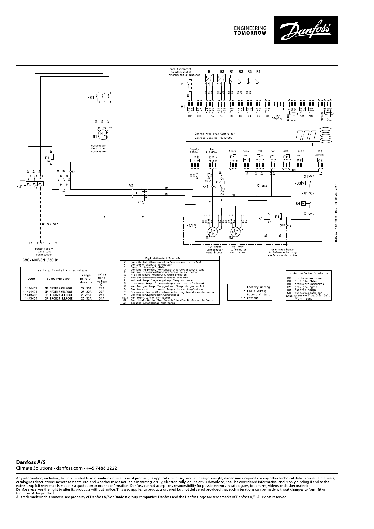
14 – Emergency running without controller
In case of controller failure, the condensing unit
can still be operated when the controller standard
wiring (picture 4) is modified into a temporary
wiring (picture 5) as described below.
This modification may be done by authorized
electricians only. Country legislations have to be
followed.
Disconnect the condensing unit from power
supply (turn hardware main switch off)
• Contact of Room Thermostat must be possible
to switch 250VAC.
• Remove wire 22 (safety input DI3) and wire 24
(room thermostat DI1) and put them together
with an insulated 250 Vac 10mm² terminal
bridge.
• Remove wire 25 (room thermostat DI1) and
wire 11 (compressor supply) and put them
together with an insulated 250VAC 10mm²
terminal bridge.
• Remove wire 6 and connect it with terminal
bridge for wire 11 and 25. A fan pressure switch
or fan speed controller can be connected in
series to wire 6.
• Remove wire 14 (crankcase heater) and connect
it to the compressor contactor terminal 22.
• Remove wire 12 (supply crankcase heater),
extend this wire by using an 250 Vac 10mm²
terminal bridge and 1,0mm² brown cable and
connect it to compressor contactor terminal 21
• Remove the large terminal block from the
controller terminals 10 to 19.
• Connect the condensing unit to power supply
(turn hardware main switch on).
15 – Maintenance
Always switch off the unit at main switch
before opening the fan door (s).
Internal pressure and surface temperature
are dangerous and may cause permanent injury.
Maintenance operators and installers require
appropriate skills and tools. Tubing temperature
may exceed 100°C and can cause severe burns.
Ensure that periodic service inspections to
ensure system reliability and as required by local
regulations are performed.
To prevent system related problems, following
periodic maintenance is recommended:
• Verify that safety devices are operational and
properly set.
• Ensure that the system is leak tight.
• Check the compressor current draw.
• Confirm that the system is operating in a way
consistent with previous maintenance records
and ambient conditions.
• Check that all electrical connections are still
adequately fastened.
• Keep the unit clean and verify the absence of
rust and oxidation on the unit components,
tubes and electrical connections.
The condenser must be checked at least once
a year for clogging and be cleaned if deemed
necessary. Access to the internal side of the
condenser takes place through the fan door.
Microchannel coils tend to accumulate dirt on
the surface rather than inside, which makes them
easier to clean than fin-&-tube coils.
• Switch off the unit at main switch before
opening the fan door.
• Remove surface dirt, leaves, fibres, etc. with
a vacuum cleaner, equipped with a brush or
other soft attachment. Alternatively, blow
compressed air through the coil from the inside
out, and brush with a soft bristle. Do not use
a wire brush. Do not impact or scrape the coil
with the vacuum tube or air nozzle.
• Before closing the fan door, turn the fan blade
in a safe position, to avoid that the door hits the
fan.
If the refrigerant system has been opened, the
system has to be flushed with dry air or nitrogen
to remove moisture and a new filter drier has to
be installed. If evacuation of refrigerant has to
be done, it shall be done in such a way that no
refrigerant can escape to the environment.
16 – Declaration of incorporation
• Pressure Equipment Directive 2014/68/EU
EN 378-2:2016 - Refrigerating systems and Heat
Pumps - Safety and environmental requirementsParts 2: Design, construction, testing, marking
and documentation.
Low Voltage Directive 2014/35/EU EN
60335-1:2012 + A11:2014- Household and
similar electrical appliances-Safety-Part 1:
General requirements-for all above mentioned
condensing units Eco-design DIRECTIVE
2009/125/ EC, establishing a framework for the
setting of Eco-design requirements for energyrelated products.
REGULATION (EU) 2015/1095, implementing Ecodesign Directive 2009/125/EC with regard to Ecodesign requirements for professional refrigerated
storage cabinets, blast cabinets, condensing units
and process Chiller.
• Condensing unit measurements are made
according to standard “EN 13771-2:2017”
4 | AN363632996019en-ZA0102 - 118A2221B
© Danfoss | Climate Solutions | 2021.10

Instructions
– Compressor and condensing units for
refrigeration-performance testing and test
methods- part 2: Condensing units.
17 - Warranty
Always transmit the model number and serial
number with any claim filed regarding this
product.
The product warranty may be void in following
cases:
• Absence of nameplate.
• External modifications, in particular, drilling,
welding, broken feet and shock marks.
• Compressor opened or returned unsealed.
• Rust, water or leak detection dye inside the
compressor.
• Use of a refrigerant or lubricant not approved
by Danfoss.
• Any deviation from recommended instructions
pertaining to installation, application or
maintenance.
• Use in mobile applications.
• Use in explosive atmospheric environment.
• No model and serial number transmitted with
the warranty claim.
18 – Disposal
Danfoss recommends that condensing
units and oil should be recycled by a
suitable company at its site.
© Danfoss | Climate Solutions | 2021.10
118A2221B - AN363632996019en-ZA0102 | 5

Instructions
OP-LPQM215-271 & OP-MPXM125-162
C
English Legend
A Ø12 Hole for Mounting
B Sight Glass
C Controller Display
E
B
A
D Air in
E Air out
F Suction Port
G Liquid Port
H
D
F
G
H4
H Nameplate
Electrical Cables
Note: all dimension are in mm
6 | AN363632996019en-ZA0102 - 118A2221B
© Danfoss | Climate Solutions | 2021.10

Instructions
3
P06 Models: OP-LPQM215-271 & OP-MPXM125-162
T1
R2
1
B4
B2
1 Compressor
2 Electric Expansion Valve
3 Micro Channel Heat Exchanger with axial fan
4 Refrigerant receiver with rotalock valve
5 Filter Drier
6 Sight Glass
7 Liquid Ball Valve
T3
R3
P2
T4
R1
78
8 Suction Ball Valve
B1 Condensing Pressure Transducer (P1)
B2 Suction Pressure Transducer (P2)
B3
High Pressure cartridge Switch (auto-reset)(PSH)
B4
Low Pressure cartridge Switch (auto-reset) (PSL)
D1
Pressure relief valve (PRV)
R1 Ambient Temperature sensor (T4)
B3
B1
R1
P1
PRV
4
R2 Discharge Temperature Sensor (T2)
R3 Suction Temperature Sensor (T3)
S1 Pressure Relief Valve
R8 Discharge Temperature Sensor (T1)
Insulation
5
6
© Danfoss | Climate Solutions | 2021.10
118A2221B - AN363632996019en-ZA0102 | 7
Code E: OP-LPQM215-271 & OP-MPXM125-162
English Legend
A1 : Optyma
A2 : EMI Filter
A3 : Liquid Injection Controller
B1,B5 : Condensing Pressure Transducer
B2 : Suction Pressure Transducer
B3 : High Pressure Switch (OFF = 31bar(g),
B4 : Low Pressure Switch (OFF = -0,3bar(g),
C1 : Start Capacitor (Compressor)
™
Plus Controller
ON = 24bar(g))
ON = 0,5bar(g))
C2 : Run Capacitor (Compressor)
C3 : Run Capacitor (Fan 1)
C4 : Run Capacitor (Fan 2)
F1 : Fuse (Control Circuit)
F2,F3 : Motor protector
K1 : Contactor
K2 : Start Relay
M1 : Compressor
M2 : Fan Motor 1
M3 : Fan Motor 2
M4 : Electronic Expansion Valve
Q1 : Main Switch
R1 : Ambient Temp. Sensor
R2,R8 : Discharge Temp. Sensor
R3 : Suction Temp. Sensor
R4,R5 : Auxiliary Temp. Sensor (optional)
R6 : Crankcase Heater
R7 : NTC Resistor
S1 : Room Thermostat (optional)
S2 : Door Limit Switch
X1 : Terminal
WD1
Supply : Supply
Fan : Fan
Alarm : Alarm
Comp. : Compressor
CCH : Crankcase Heater
Aux : Auxiliary
8 | AN363632996019en-ZA0102 - 118A2221B
© Danfoss | Climate Solutions | 2021.10
 Loading...