

Page 1
J
Instructions
Optyma™ High Ambient 52 Pack
OP-LPHE/MPZE
L
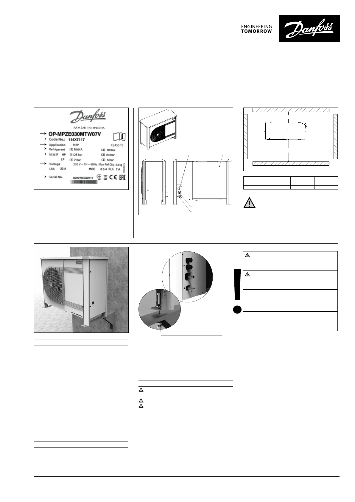
A
B
C
D
E
F
G
A: Model
B: Code number
C: Application, Protection
D: Refrigerant
E: Housing Service Pressure
F: Supply voltage, Locked Rotor Ampere,
Maximum Current Consumption
G: Serial Number and bar code
Picture 2
1 – Introduction
These instructions pertain to Optyma™ High
Ambient 52 Pack condensing units OP-LPHE/
MPZE (R404A, R134a) used for refrigeration systems. They provide necessary information regarding safety and proper usage of this product.
The condensing unit includes following:
• Reciprocating compressor
• Microchannel heat exchanger
• Dual pressure switches
• Service valves suction/liquid
• Weather proof housing
• Filter drier
• Receiver with stop valve
• Sight glass
• Solenoid valve
• Oil separator (LBP only)
• Discharge thermostat (LBP Only)
2 – Handling and storage
• It is recommended not to open the packaging
before the unit is at the nal place for installation.
• Handle the unit with care. The packaging allows for the use of a forklift or pallet jack. Use
KH
I
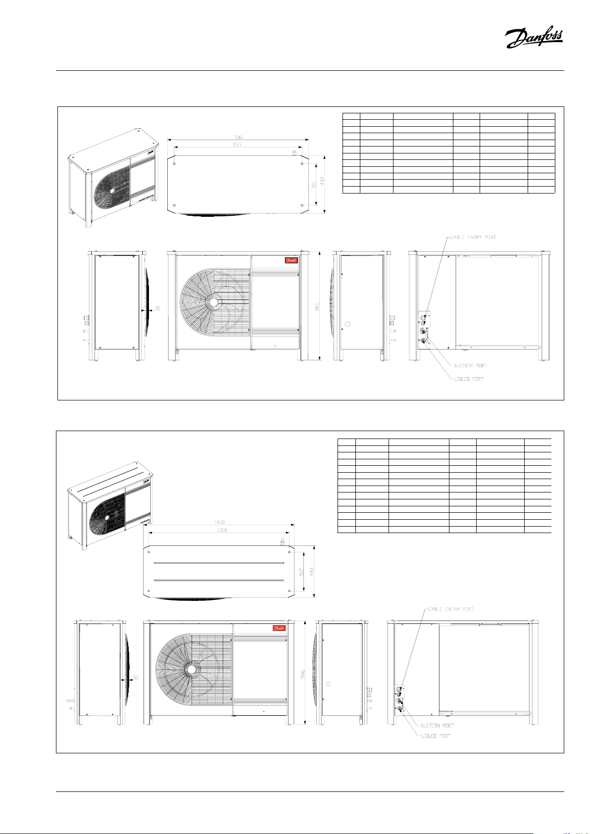
H: Cable entry ports
I: Suction port
J: Liquid port
K: Microchannel heat exchanger
Picture 3
Mounting bolts
appropriate and safe lifting equipment.
• Store and transport the unit in an upright position.
• Store the unit between -35°C and 60°C.
• Don’t expose the packaging to rain or corrosive
atmosphere.
• After unpacking, check that the unit is complete and undamaged.
3 – Installation precautions
Do not braze as long the condensing unit is
under pressure.
Never place the unit in a ammable atmosphere
Place the unit in such a way that it is not blocking
or hindering walking areas, doors, windows or similar.
• Ensure adequate space around the unit for air
circulation and to open doors. Refer to picture1
for minimal values of distance to walls.
• Avoid installing the unit in locations which are daily
exposed to direct sunshine for longer periods.
• Avoid installing the unit in aggressive and dusty environments.
• Ensure a foundation with horizontal surface
(less than 3° slope), strong and stable enough
to carry the entire unit weight and to eliminate
vibrations and interference.
N
M
Picture 1 : Minimum mounting distances
L
[mm]
250 650 550 550
Installation and servicing of the
condensing units by qualied
personnel only. Follow these instructions
and sound refrigeration engineering practice
relating to installation, commissioning,
maintenance and service.
The condensing unit must only be used for
its designed purpose(s) and within its scope of
application.
Under all circumstances, the EN378 (or
other applicable local safety regulation)
requirements must be fullled.
The condensing unit is delivered under nitrogen gas pressure (1 bar) and hence it cannot
be connected as it is; refer to the «installation»
section for further details.
The condensing unit must be handled with caution in the vertical position (maximum oset
from the vertical : 15°)
• The unit ambient temperature may not exceed
52°C during o-cycle.
• Ensure that the power supply corresponds to
the unit characteristics (see nameplate).
• When installing units for HFC refrigerants, use
equipment specically reserved for HFC refrigerants which was never used for CFC or HCFC
refrigerants.
• Use clean and dehydrated refrigeration-grade
copper tubes and silver alloy brazing material.
• Use clean and dehydrated system components.
• The suction piping connected to the compressor must be exible in 3 dimensions to dampen
vibrations. Furthermore piping has to be done
in such a way that oil return for the compressor is ensured and the risk of liquid slug over in
compressor is eliminated.
• For all units factory setting of fan speed
controller to be 15 ±1 bar.
• For refrigerant R134a, adjust the factory pressure setting of XGE-2C (code no: 061H3144)
from 15 ±1 bar to recommended setting 8 bar
by rotating the screw by 9 turns in counter
clockwise direction.
M
[mm]
[mm]
O
N
O
[mm]
1 | © Danfoss | DCS (CC)| 2017.12
FRCC.PI.056.A2.02
Page 2
Instructions
4 – Installation
• The installation in which the condensing unit is installed must comply to EU Pressure directive (PED)
no. 2014/68/EU. The condensing unit itself is not a
”unit” in the scope this directive. Under all circumstances local safety regulations must be fullled.
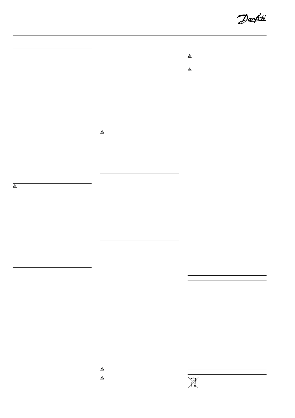
• The unit must be securely installed on a stable
and rigid support, and xed from the beginning. See picture 2.
• It is recommended to install the unit on rub-
ber grommets or vibration dampers . Rubber
pads with mounting bolts are supplied.
• Slowly release the nitrogen holding charge
through the schrader port.
• Connect the unit to the system as soon as possible
to avoid oil contamination from ambient moisture.
• Avoid material entering into the system while
cutting tubes. Never drill holes where burrs
cannot be removed.
• Braze with great care using state-of-the-art technique and vent piping with nitrogen gas ow.
• Connect the required safety and control devices. When the schrader port is used for this,
remove the internal valve.
• CU function and reliability is ensured/veried
for super heat 10K (SH 10K) condition so, it is
recommended to insulate the suction pipe up
to the compressor inlet with 19 mm thick insulation.
5 – Leak detection
Never pressurize the circuit with oxygen or
dry air. This could cause re or explosion.
• Do not use dye for leak detection.
• Perform a leak detection test on the complete
system.
• The maximum test pressure is 32 bar.
• When a leak is discovered, repair the leak and
repeat the leak detection.
6 – Vacuum dehydration
• Never use the compressor to evacuate the system.
• Connect a vacuum pump to both the LP & HP
sides.
• Pull down the system under a vacuum of 500
μm Hg (0.67 mbar) absolute.
• Do not use a megohmmeter nor apply power
to the compressor while it is under vacuum as
this may cause internal damage.
7 – Electrical connections
• Switch o and isolate the main power supply.
• Ensure that power supply can not be switched
on during installation.
• All electrical components must be selected as
per local standards and unit requirements.
• Refer to wiring diagram for electrical connections details.
• Ensure that the power supply corresponds
to the unit characteristics and that the power
supply is stable (nominal voltage ±10% and
nominal frequency ±2,5 Hz).
• Dimension the power supply cables according
to unit data for voltage and current.
• Protect the power supply and ensure correct
earthing.
• Make the power supply according to local standards and legal requirements.
•
The unit is equipped with high and low pressure
switches, which directly cut the power supply to
the compressor in case of activation.
8 – Filling the system
• Wear protective stu like goggles and protective gloves.
• Never start the compressor under vacuum.
Keep the compressor switched o.
• Before charging the refrigerant, verify that the
oil level is between ¼ and ¾ on the compressor
oil sight glass. If additional oil is required please
refer to the compressors label for type of oil.
• Use only the refrigerant for which the unit is
designed for.
• Fill the refrigerant in liquid phase into the
condenser or liquid receiver. Ensure a slow
charging of the system to 4 – 5 bar for R404A.
• Do not put liquid refrigerant through suction line.
• It is not allowed to mix additives with the oil
and/or refrigerant
• The remaining charge is done until the installation has reached a level of stable nominal
condition during operation.
• Never leave the lling cylinder connected to
the circuit.
9 – Verification before commissioning
Use safety devices in compliance with both
generally and locally applicable regulations and
safety standards.
• Verify that all electrical connections are properly
fastened and in compliance with local regulations.
• When a crankcase heater is required, it must be
energized at least 12 hours before initial startup and start-up after prolonged shut-down
period.
10 – Start-up
• Never start the unit when no refrigerant is char-
ged.
• All service valves must be in the open position.
See picture 3.
• Check compliance between unit and power
supply.
• Check that the crankcase heater is working.
• Check that the fan can rotate freely.
• Balance the High Pressure / Low Pressure.
• Energize the unit. It must start promptly. If
the compressor does not start, check wiring
conformity, voltage on terminals and sequence
phase.
11 – Check with running unit
• Check the fan rotation direction. Air must ow
from the condenser towards the fan.
• Check current draw and voltage.
• Check suction superheat to reduce risk of slug-
ging.
• When a sight glass is provided observe the oil
level at start and during operation to conrm
that the oil level remains visible.
• Respect the operating limits.
• Check all tubes for abnormal vibration. Move-
ments in excess of 1.5 mm require corrective
measures such as tube brackets.
• When needed, additional refrigerant in liquid
phase may be added in the low-pressure side as
far away as possible from the compressor. The
compressor must be operating during this process.
• Do not overcharge the system.
• Never release refrigerant to atmosphere.
• Before leaving the installation site, carry out
a general installation inspection regarding
cleanliness, noise and leak detection.
• Record type and amount of refrigerant charge
as well as operating conditions as a reference
for future inspections.
12 – Maintenance
Always switch o the unit at main switch
before remove fan panel.
Internal pressure and surface temperature
are dangerous and may cause permanent injury.
Maintenance operators and installers require
appropriate skills and tools. Tubing temperature
may exceed 100°C and can cause severe burns.
Ensure that periodic service inspections to
ensure system reliability and as required by local
regulations are performed.
This appliance is not intended for use by persons (including children) with reduced physical,
sensory or mental capabilities, or lack of experience and knowledge, unless they have been given supervision or instruction concerning use of
the appliance by a person responsible for their
safety. Children should be supervised to ensure
that they do not play with the appliance
To prevent system related problems, following
Periodic maintenance is recommended:
• Verify that safety devices are operational and
properly set.
• Ensure that the system is leak tight.
• Check the compressor current draw.
• Conrm that the system is operating in a way
consistent with previous maintenance records
and ambient conditions.
• Check that all electrical connections are still
adequately fastened.
• Keep the unit clean and verify the absence of
rust and oxidation on the unit components,
tubes and electrical connections.
The condenser must be checked at least once
a year for clogging and be cleaned if deemed
necessary. Access to the internal side of the
condenser takes place through the fan panel.
Microchannel coils tend to accumulate dirt on
the surface rather than inside, which makes
them easier to clean than n-&-tube coils.
• Switch o the unit at main switch before re-
move any panel from the condensing unit.
• Remove surface dirt, leaves, bres, etc. with
a vacuum cleaner, equipped with a brush or
other soft attachment. Alternatively, blow compressed air through the coil from the inside out,
and brush with a soft bristle. Do not use a wire
brush. Do not impact or scrape the coil with the
vacuum tube or air nozzle.
If the refrigerant system has been opened, the
system has to be ushed with dry air or nitrogen
to remove moisture and a new lter drier has to
be installed. If evacuation of refrigerant has to be
done, it shall be done in such a way that no refrigerant can escape to the environment.
13 - Warranty
Always transmit the model number and serial number with any claim led regarding this product.
The product warranty may be void in following
cases:
• Absence of nameplate.
• External modications; in particular, drilling,
welding, broken feet and shock marks.
• Compressor opened or returned unsealed.
• Rust, water or leak detection dye inside the
compressor.
• Use of a refrigerant or lubricant not approved
by Danfoss.
• Any deviation from recommended instructions
pertaining to installation, application or maintenance.
• Use in mobile applications.
• Use in explosive atmospheric environment.
• No model number or serial number transmit-
ted with the warranty claim.
14 – Disposal
Danfoss recommends that condensing
units and oil should be recycled by a
suitable company at its site.
2 | © Danfoss | DCS (CC) | 2017.12
FRCC.PI.056.A2.02
Page 3
Instructions
OP-MPZE030 - 048, OP-LPHE048 - 068
2SW\PD+LJK$PELHQW3DFN
APP UNIT DESCRIPTION CHASSIS POWER SUPPLYCOMP
LBP
LBP
LBP
LBP
LBP
MBP
MBP
MBP
MBP
MBP
114X7140LBP
114X7150
114X7153
114X7120
114X7141
114X7151
114X7146
114X7156
114X7117
114X7123
114X7157
OP-LPHE048NTW07Q
OP-LPHE048NTW07N
OP-LPHE048NTW07V
OP-LPHE068NTW07V
OP-LPHE068NTW07Q
OP-LPHE068NTW07N
OP-MPZE030MTW07N
OP-MPZE030MTW07Q
OP-MPZE048MTW07V
OP-MPZE048MTW07N
OP-MPZE048MTW07Q
H2
H2
H2
H2
H2
H2
H2
H2
H2
H2
H2
230V/3/~60Hz
230V/1N/~60Hz
380V/3N/~60Hz
380V/3N/~60Hz
230V/3/~60Hz
230V/1N/~60Hz
230V/1N/~60Hz
230V/3/~60Hz
380V/3N/~60Hz
230V/1N/~60Hz
230V/3/~60Hz
NTZ048
NTZ048
NTZ048
NTZ068
NTZ068
NTZ068
MTZ018
MTZ018
MTZ028
MTZ028
MTZ028
OP-MPZE060 - 068 - 086, OP-LPHE108-136
APP UNIT DESCRIPTION CHASSIS POWER SUPPLYCOMP
LBP
LBP
LBP
LBP
MBP
MBP
MBP
MBP
MBP
MBP
MBP
MBP
114X7142LBP
114X7154
114X7152
114X7121
114X7143
114X7126
114X7158
114X7147
114X7148
114X7159
114X7118
114X7149
114X7160
OP-LPHE108NTW07Q
OP-LPHE108NTW07V
OP-LPHE108NTW07N
OP-LPHE136NTW07V
OP-LPHE136NTW07Q
OP-MPZE060MTW07V
OP-MPZE060MTW07Q
OP-MPZE060MTW07N
OP-MPZE068MTW07N
OP-MPZE068MTW07Q
OP-MPZE086MTW07V
OP-MPZE086MTW07N
OP-MPZE086MTW07Q
H3
H3
H3
H3
H3
H3
H3
H3
H3
H3
H3
H3
H3
230V/3/~60Hz
380V/3N/~60Hz
230V/1N/~60Hz
380V/3N/~60Hz
230V/3/~60Hz
380V/3N/~60Hz
230V/3/~60Hz
230V/1N/~60Hz
230V/1N/~60Hz
230V/3/~60Hz
380V/3N/~60Hz
230V/1N/~60Hz
230V/3/~60Hz
NTZ108
NTZ108
NTZ108
NTZ136
NTZ136
MTZ036
MTZ036
MTZ036
MTZ040
MTZ040
MTZ050
MTZ050
MTZ050
FRCC.PI.056.A2.02
2SW\PD+LJK$PELHQW3DFN
© Danfoss | DCS (CC) | 2017.12 | 3
Page 4

Instructions
OP-MPZE108 - 121 - 171, OP-LPHE215 - 271
APP UNITDESCRIPTION CHASSIS POWER SUPPLYCOMP
LBP
LBP
LBP
MBP
MBP
MBP
MBP
MBP
MBP
MBP
114X7144LBP
114X7155
114X7122
114X7145
114X7124
114X7127
114X7137
114X7128
114X7138
114X7119
114X7139
OP-LPHE215NTW07Q
OP-LPHE215NTW07V
OP-LPHE271NTW07V
OP-LPHE271NTW07Q
OP-MPZE108MTW07N
OP-MPZE108MTW07V
OP-MPZE108MTW07Q
OP-MPZE0121MTW07V
OP-MPZE121MTW07Q
OP-MPZE171MTW07V
OP-MPZE171MTW07Q
H4
H4
H4
H4
H4
H4
H4
H4
H4
H4
H4
230V/3/~60Hz
380V/3N/~60Hz
380V/3N/~60Hz
230V/3/~60Hz
230V/1N/~60Hz
380V/3N/~60Hz
230V/3/~60Hz
380V/3N/~60Hz
230V/3/~60Hz
380V/3N/~60Hz
230V/3/~60Hz
NTZ215
NTZ215
NTZ271
NTZ271
MTZ064
MTZ064
MTZ064
MTZ072
MTZ072
MTZ100
MTZ100
2SW\PD+LJK$PELHQW3DFN
4 | © Danfoss | DCS (CC) | 2017.12
FRCC.PI.056.A2.02
Page 5

Instructions
KP 15, 15A, 17W, 17B
-1 bar (Pe)(30in.Hg)
When used acc. to UL regulations
AC1 16 ADC 11
LR 112A AC316 A400 V 12 W
AC11 10 A220 V
PHteser .nam ,PLteser .tua ,PL
Manual test
Convertible reset
KP 15 060-1154, 060-1220, 060-1261, 060-1263, 060-1 283
LP-man. LP-auto. LP-auto.LP-man.
HP-man. HP-man. HP-auto.HP-auto.
Convertible reset
KP 17B 060-539366, 060-539466
FRCC.PI.056.A2.02
LP-auto.
HP-man.
LP-auto.
HP-auto.
© Danfoss | DCS (CC) | 2017.12 | 5
Page 6

Instructions
Code N: OP-MPZE030 - 048, OP-LPHE048 - 068
Code N: OP-MPZE060 - 068 - 086, OP-LPHE108 - 136
Legend
BK black
BU blue
BN brown
GY grey
RD red
WH white
A1 Power Supply Monitoring Relay
B1 Fan Speed Controller
B2 Dual Pressure Switch
C1 Start Capacitor- Compressor
C2 Run Capacitor-Compressor
C3,C4 Run capacitor-Fan
6 | © Danfoss | DCS (CC) | 2017.12
E1 Crankcase Heater
F1 Main Switch
F2 Overload Relay
F3,F4 Fuse Control Circuit
F5 Discharge Thermostat (LBP only)
M1 Compressor
M2,M3 Fan Motor
K1 Compressor contactor
K2 Start Relay
R1,R2 Bleeder Resistor
S1 Door Limit Switch
FRCC.PI.056.A2.02
Page 7

Instructions
Code N: OP-MPZE108
Code V: OP-MPZE048, OP-LPHE048 - 068
Legend
BK black
BU blue
BN brown
GY grey
RD red
WH white
FRCC.PI.056.A2.02
A1 Power Supply Monitoring Relay
B1 Fan Speed Controller
B2 Dual Pressure Switch
C1 Start Capacitor- Compressor
C2 Run Capacitor-Compressor
C3,C4 Run capacitor-Fan
E1 Crankcase Heater
F1 Main Switch
F2 Overload Relay
F3,F4 Fuse Control Circuit
F5 Discharge Thermostat (LBP only)
M1 Compressor
M2,M3 Fan Motor
K1 Compressor contactor
K2 Start Relay
R1,R2 Bleeder Resistor
S1 Door Limit Switch
© Danfoss | DCS (CC) | 2017.12 | 7
Page 8

Instructions
Code V: OP-MPZE060 - 086, OP-LPHE108 - 136
Code V: OP-MPZE108 - 121 - 171, OP-LPHE215 - 271
Legend
BK black
BU blue
BN brown
GY grey
RD red
WH white
A1 Power Supply Monitoring Relay
B1 Fan Speed Controller
B2 Dual Pressure Switch
C1 Start Capacitor- Compressor
C2 Run Capacitor-Compressor
C3,C4 Run capacitor-Fan
8 | © Danfoss | DCS (CC) | 2017.12
E1 Crankcase Heater
F1 Main Switch
F2 Overload Relay
F3,F4 Fuse Control Circuit
F5 Discharge Thermostat (LBP only)
M1 Compressor
M2,M3 Fan Motor
K1 Compressor contactor
K2 Start Relay
R1,R2 Bleeder Resistor
S1 Door Limit Switch
FRCC.PI.056.A2.02
Page 9

Instructions
Code Q: OP-MPZE030 - 048, OP-LPHE048 - 068
Code Q: OP-MPZE060 - 068 - 086, OP-LPHE108 - 136
Legend
BK black
BU blue
BN brown
GY grey
RD red
WH white
FRCC.PI.056.A2.02
A1 Power Supply Monitoring Relay
B1 Fan Speed Controller
B2 Dual Pressure Switch
C1 Start Capacitor- Compressor
C2 Run Capacitor-Compressor
C3,C4 Run capacitor-Fan
E1 Crankcase Heater
F1 Main Switch
F2 Overload Relay
F3,F4 Fuse Control Circuit
F5 Discharge Thermostat (LBP only)
M1 Compressor
M2,M3 Fan Motor
K1 Compressor contactor
K2 Start Relay
R1,R2 Bleeder Resistor
S1 Door Limit Switch
© Danfoss | DCS (CC) | 2017.12 | 9
Page 10

Code Q: OP-MPZE108 - 121 - 171, OP-LPHE215 - 271
Legend
BK black
BU blue
BN brown
GY grey
RD red
WH white
A1 Power Supply Monitoring Relay
B1 Fan Speed Controller
B2 Dual Pressure Switch
C1 Start Capacitor- Compressor
C2 Run Capacitor-Compressor
C3,C4 Run capacitor-Fan
E1 Crankcase Heater
F1 Main Switch
F2 Overload Relay
F3,F4 Fuse Control Circuit
F5 Discharge Thermostat (LBP only)
M1 Compressor
M2,M3 Fan Motor
K1 Compressor contactor
K2 Start Relay
R1,R2 Bleeder Resistor
S1 Door Limit Switch
Danfoss A/S
6430 Nordborg
Denmark
Danfoss can accept no responsibility for possible errors in catalogues, brochures and other printed material. Danfoss reserves the right to alter its products without notice. This
also applies to products already on order provided that such alterations can be made without subsequential changes being necessary in specications already agreed. All trademarks in this material are property of the respective companies. Danfoss and the Danfoss logotype are trademarks of Danfoss A/S. All rights reserved.
10 | © Danfoss | DCS (CC) | 2017.12
FRCC.PI.056.A2.02
 Loading...