

Page 1

Data Sheet
Data sheet
Plug & Spray unit
Plug and Spray Unit
NPS
hpp.danfoss.com
hpp.danfoss.com
Page 2

Data sheet | Plug & Spray unit NPS
Table of Contents
Contents
1. General information.....................................................................3
2. Component description.................................................................5
2.1 PAHT high-pressure pump ..............................................................5
2.2 Electric motor ..........................................................................5
2.2.1 Danfoss FCP 106 drive motor ............................................................5
2.3 Aluminium cast bell housing and exible coupling ......................................5
2.4 Galvanized steel frame .................................................................5
2.5 Connection block .......................................................................5
2.6 Water lter .............................................................................5
2.7 Electrical connection box, optional .....................................................5
2.8 Supply pressure gauge .................................................................5
2.9 Pressure relief valve VRH 5 (30) CA cartridge .............................................5
2.10 Filter bleed button .....................................................................5
2.11 High-pressure gauge ...................................................................5
2.12 Check valve - inlet 3/4” ..................................................................5
2.13 Ball valve G 3/8” female .................................................................5
2.14 Inlet G 3/4” female ......................................................................5
2.15 High-pressure outlet G 3/8” female, optional ............................................5
2.16 High-pressure hose .....................................................................6
2.17 High-temperature switch ...............................................................6
2.18 Low-pressure hose .....................................................................6
2.19 MBS 3050 pressure transmitter ..........................................................6
2.20 Low-pressure switch ....................................................................6
2.21 Check valve - outlet .....................................................................6
2.22 Swivel union 3/4” .......................................................................6
3. P&ID ....................................................................................6
4. Technical data ..........................................................................7
5. Dimensions [mm] .......................................................................8
6. Local control panel......................................................................9
7. Opt i o ns .................................................................................9
8. Electrical connection box ..............................................................10
2
AI309730711498en-0 00901 | 02.2021
Page 3

Data sheet | Plug & Spray unit NPS
1. General information
The Danfoss Plug & Spray unit is designed for
humidication and adiabatic cooling systems
based on the high-pressure principle. The units
are available in a constant speed version (CS)
with IEC electric motor, as well as in a version
with constant pressure control using a Danfoss
FCP 106 variable speed drive motor (VS).
The Plug & Spray unit is available with 6 dierent
pump sizes (see Technical data, sec. 4) to match
the required ow demand. The motor power is
dimensioned to provide design ow at
a system pressure of max. 100 barg or 1,450 psig.
The Danfoss high-pressure axial piston pumps
provide excellent pressure stability at high
energy eciency and low noise level. Pulsation
dampeners are superuous.
The Plug & Spray unit comprises all necessary
components to ensure the best possible
performance, maximum service life with
maximum protection of the pump. It is very
compact, requires very little space and is suitable
for both wall and oor mounting.
The Danfoss Plug & Spray unit can be operated
with ordinary tap water as well as with all kinds
of technical water (distilled, de-ionised and
demineralised water).
The Plug & Spray unit is suitable for a variety of
applications, such as:
• High-pressure hymidication and adia batic
cooling in HVAC systems (Air-handling
units) i.e. in oces, server rooms etc.
• Open space humidication system in
production halls, storages etc.
• Humidication and adiabatic cooling
in animal farms, greenhouses and composting, server rooms
• Electrostatic Discharge (ESD) control
• Adiabatic outdoor cooling i.e. in pools,
bars, restaurants etc.
• Dust suppression and dust binding in
manufacturing and clean rooms
• Gas turbine inlet cooling and NOx control
• Odour control and soil lters
• Water mist clouds in theme parks,
exhibitions etc.
2
1
Pumps: PAHT 2 to PAHT 12.5
2
Electric motor, standard IEC or VS units with
Danfoss FCP 106 Drive Motor
3
Aluminium cast bell housing and exible
coupling
5
3
1
4
4
Galvanized steel frame for oor mounting
5
Very compact and reliable connection block,
see details on page 5
AI309730711498en-0 00901 | 02.2021
3
Page 4

Data sheet | Plug & Spray unit NPS
6
Water lter 5” or 10”,
6
7
10 μm absolute,
β ≥ 5,000
Optional electrical
7
box.
CS or VS versions
available.
8
21
10
9
11
22
12
15
13
20
19
Supply pressure gauge 0-10 barg
8
Pressure relief valve VRH 5 (30) CA cartridge,
9
adjustable 20–100 barg / 363–1450 psig
(25–140 barg / 363–2031 psig)
10
Filter bleed button
11
High-pressure gauge
12
Check valve - inlet ¾”
13
Ball valve G 3/8” female
14
Inlet G 3/4” female
15
High-pressure outlet G 3/8” female, optional
17
18
High-pressure hose
16
17
High-temperature switch
18
Low-pressure hose
19
MBS 3050 pressure transmitter on VS-unit
20
Low-pressure switch
21
Check valve - outlet
22
Swivel union 3/4”
16
14
4
AI309730711498en-0 00901 | 02.2021
Page 5

Data sheet | Plug & Spray unit NPS
2. Component
description
The components described in this chapter refer
to the images on page 3 and 4.
2.1 PAHT high-pressure pump
1
The heart of the Plug & Spray unit is the Danfoss
axial piston high-pressure pump. The pump is
water lubricated and fulls the most stringent
hygiene requirements as no lubricants or
chemicals are involved at all.
Danfoss PAHT pumps are designed for long
periods of service-free operation to provide
customers with low maintenance and life cycle
costs. Provided that the pump is installed and
operated according to Danfoss specications,
Danfoss PAHT pumps typically run 8,000 hours
between service routines.
We recommend that you inspect your pump
after 8,000 hours of operation even if it is
running without any noticeable problems.
2.2 Electric motor
2
The electric motor is dimensioned to provide
sucient power for maximum ow at 100 barg/
1,450 psig system pressure. The motor is a
standard IEC 3-phase 400 V, 50 Hz asynchronous
motor.
2.2.1 Danfoss FCP 106 drive motor
The variable speed drive motor in connection
with a pressure transmitter allows adjusting the
pump capacity to the actual demand of the
application, keeping the system pressure
constant.
The FCP 106 has a built-in PID-controller and 24 V
DC transmitter power supply.
2.6 Water lter
6
The system comprises a 5” or 10” (10, 12,5 VS),
10-micron ne lter with a β-value ≥ 5,000 abs.
The lter protects the pump against rapid wear
caused by contamination of the supply water
and – as a second benet – prevents the nozzles
from clogging. The lter cartridge is easy to
replace.
2.7 Electrical connection box, optional
7
Both CS and VS units can be delivered with an
electrical connection box, please see sec. 8.
2.8 Supply pressure gauge
8
It allows monitoring the supply pressure under
operation and the condition of the lter. The
lter should be changed when the supply
pressure is below 2 barg (29 psig).
2.9 Pressure relief valve
VRH 5 (30) CA cartridge
9
The relief valve is integrated in the connection
block with internal recirculation loop back to the
lter. It works as a safety valve in case the
discharge is blocked and allows adjusting the
system pressure under normal operation. At 20
°C (68 °F) water temperature 90% of the water
can be run over the bypass loop (recirculation).
Pressure range: 20–100 barg / 363–1450 psig
(25–140 barg / 363–2031 psig).
2.10 Filter bleed button
10
It is important that there is no air in the system.
At commissioning air can be bled from the lter
by using the lter bleed button.
2.3 Aluminium cast bell housing and
exible coupling
3
The bell housing is made of cast aluminium. The
electric motor and the pump are directly coupled
with a exible coupling. The bell housing
requires minimum space and is lightweighted.
The transmission is maintenance free and cost
ecient compared to traditional belt drives.
2.4 Galvanized steel frame
4
The base frame is designed for oor mounting;
however it can be mounted on a wall with
suitable support bars. The base frame concept
allows adding numerous options.
2.5 Connection block
5
A central connection block with integrated
pressure relief valve provides a very compact and
reliable solution to connect all other necessary
components such as gauges, switches etc.
Service friendly gasket concept:
All HP components as well as the connections to
the pump are equipped with bonded seals,
which provide easy and reliable connections.
2.11 High-pressure gauge
11
It allows monitoring the discharge pressure
under operation and during adjusting the
pressure relief valve.
Pressure range: 0-160 barg (0-2,321 psig)
2.12 Check valve - inlet 3/4”
12
In order to make back-ow impossible, a check
valve at the water supply is mandatory when
connecting the system to the public utilities.
2.13 Ball valve G 3/8” female
13
The ball valve allows to interrupt the water
supply i.e. for lter change or pump service.
2.14 Inlet G 3/4” female
14
Connect your water supply to the inlet.
2.15 High-pressure outlet G 3/8” female,
optional
15
Not used by Danfoss.
AI309730711498en-0 00901 | 02.2021
5
Page 6
Data sheet | Plug & Spray unit NPS
2.16 High-pressure hose
To avoid vibrations in the system Danfoss always
use a exible high-pressure hose from the pump
outlet to the connection block.
2.17 High-temperature switch
The water temperature is monitored to prevent
overheating. The switch is set to 50 °C(122 °F).
regulation (only with VS units).
16
Pressure range: 0-160 barg (0-2,361 psig)/
4-20 mA.
2.20 Low-pressure switch
20
If insucient supply pressure occurs, the pump
17
can be damaged by cavitation or dry running.
A low-pressure switch set to 1.6 barg(23 psig) abs.
protects the pump.
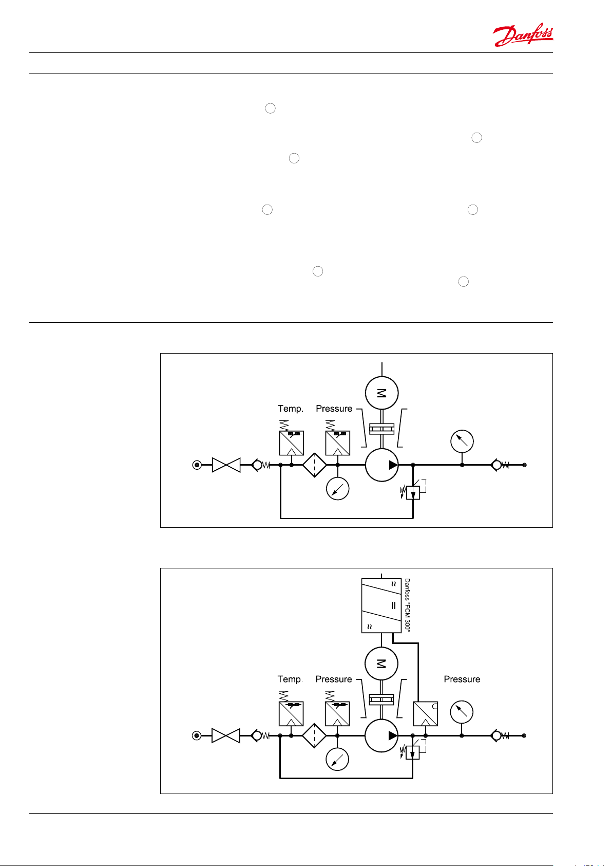
3. P&ID
2.18 Low-pressure hose
18
To avoid vibrations in the system Danfoss always
use a exible low-pressure hose from the
connection block to the pump inlet.
2.19 MBS 3050 pressure transmitter
19
The pressure transmitter is connected to the
internal PID controller of the FCP 106 Drive
Motor, which is set up for constant pressure
Constant speed versions:
2.21 Check valve - outlet
21
The connection block is mounted with a check
valve and a male connector for a 12 mm pipe. By
removing the male connector the outlet can be
changed to G 3/4” female.
2.22 Swivel union 3/4”
22
The swivel union allows establishing the water
supply from the top, back, front or bottom.
Variable speed versions:
6
AI309730711498en-0 00901 | 02.2021
Page 7
Data sheet | Plug & Spray unit NPS
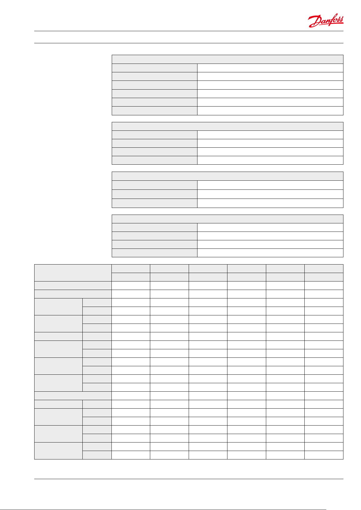
4. Technical data
Water supply
Connection ø19 mm hose tting or G 3/4” female thread
Pressure min. 2 barg (28 psig), max. 4 barg (56 psig)
Filter 10 μm absolute, β ≥ 5,000, 5” or 10” (10, 12.5 VS)
Pressure switch 1.6 barg (23 psig), 250 V AC/24 V DC, 0.5 A
Temperature switch 50 °C ± 5 °C, 250 V AC/24 V DC, 0.5 A
High pressure outlet 12 mm pipe
High-pressure pump
Max. discharge pressure 100 barg (1,450 psig), continuous
Min. pump speed 1,000 rpm
Max. pump speed 3,000 rpm, 2,400 rpm, NPS 10, 12.5 VS
Discharge connection G3/8“ female, 3/8“ NPT adaptor on request
Pressure relief valve
Typ e VRH 5 (30) CA Cartridge
Capacity max. 30 l/min / 1,800 l/h / 8 gpm
Adjustment range 25–100 barg / 363–1450 psig (25–140 barg / 363–2031 psig)
Environmental conditions
Water temperature supply +3 °C – +50 °C / 37 °F – 122 °F
Ambient temperature +3 °C – +50 °C / 37 °F – 122 °F, VS units max. 40 °C / 104 °F
Storage temperature -25 °C – +65 °C / 13 °F – 149 °F with frost protection!
Operation and storage humidity 5–95% rF, non condensing
Typ e
Ordering code 180U3300 180U3301 180U3302 180U3303 180U3304 180U3305
Pump type PAHT 2 PAHT 2 PAHT 3.2 PAHT 4 PAHT 6.3 PAHT 10
Min. ow at
100 barg / 1450
Max. ow at
100 barg / 1450
Motor type Pole 6 4 4 4 4 4
Rated power
Motor voltage
Motor current
FLA
Cos φ 0.72 0.77 0.79 0.79 0.82 0.83
Speed rpm 900 1,400 1,400 1, 400 1,420 1,420
Weight without
options
Shipping
Crate size
(H×W×D)
l/h 7.5 10.0 20.0 30.0 50.0 75.0
psig*
gal/h 2.0 2.6 5.3 7.9 13 .2 19. 8
l/h 75 100 200 300 500 750
psig*
gal/h 2.0 26.4 52.8 79.2 132.0 198 .0
kW @ 50 Hz 0.55 0.75 1. 50 1.50 2.20 3.00
kW @ 60 Hz 0.66 0.90 1.80 1.80 2.65 3.60
V @ 50 Hz 3×230/400 3×230/400 3×230/400 3×230/400 3×230/400 3×230/400
V @ 60 Hz 3x280/480 3x280/480 3x280/480 3x280/480 3x280/480 3x280/480
A 1.7 1.9 3.5 3.5 4.7 6.3
V 400 400 400 400 400 400
kg 55 55 58 58 67 73
lbs 121 121 12 8 128 148 161
kg 85 85 88 88 97 103
lbs 187 187 19 4 194 214 227
m 0.8 x 0.6 x 0.8 0.8 x 0.6 x 0.8 0.8 x 0.6 x 0.8 0.8 x 0.6 x 0.8 0.8 x 0.6 x 0.8 0.8 x 0.6 x 0.8
inch 31.5 x 23.6 x 31.5 31.5 x 23.6 x 31.5 31.5 x 23.6 x 31.5 31.5 x 23.6 x 31.5 31.5 x 23.6 x 31.5 31.5 x 23.6 x 31.5
NPS NPS NPS NPS NPS NPS
1CS 2CS 3.2CS 4CS 6.3CS 10CS
* Minimum and maximum ow increase with decreasing system pressure. Please observe technical data in pump data sheet.
AI309730711498en-0 00901 | 02.2021
7
Page 8

Data sheet | Plug & Spray unit NPS
Mounted with with Danfoss FCP 106 Drive Motor
Typ e
Ordering code 180U330 6 180U3307 180U3308 180U3309 18 0U3310 18 0U3311 18 0U3312
Pump type PAH T 12. 5 PAHT 2 PAHT 3.2 PAHT 4 PAHT 6.3 PAHT 10 PAHT 12 .5
Min. ow at
100 barg*
Max. ow at
100 barg*
Motor type Pole 4 2 2 2 2 4 4
Rated power
Motor voltage
Motor current
FLA
Cos φ 0.83 1 1 1 1 1 1
Speed rpm 1, 440
Weight without
options
Shipping
Crate size
(H×W×D)
l/h 100 10 20 30 50 75 100
gph 26.4 2.64 5.3 7.92 13.2 19.8 26.4
l/h 1,000 300 450 600 1,000 1,350 1,650
gph 264.0 79.2 119. 0 158.0 264.0 356.0 443.0
kW @ 50 Hz 4.00 1. 50 2.20 2.20 4.00 7. 50 7.50
kW @ 60 Hz 4.80 1. 80 2.65 2.65 4.80 9.00 9.00
V @ 50 Hz 3×400/690 3×230/400 3×230/40 0 3×230/4 00 3×400/690 3×400/690 3×400/690
V @ 60 Hz 3x480/830 3x280/480 3x280/480 3x280/480 3x480/830 3x480/830 3x480/830
A 8.2 3.3/2.6 4.7/3.7 4.7/3.7 7.9/6 .4 11/ 8 .7 11/8.7
V 400 380/480 380/480 380/480 380/480 380/480 380/480
kg 76 64 70 70 81 10 4 104
lbs 168 141 15 4 154 179 229 229
kg 106 94 10 0 100 111 134 134
lbs 234 207 220 220 245 295 295
m 0.8 x 0.6 x 0.8 0.8 x 0.6 x 0.8 0.8 x 0.6 x 0.8 0.8 x 0.6 x 0.8 0.8 x 0.6 x 0.8 0.8 x 0.6 x 0.8 0.8 x 0.6 x 0.8
inch
NPS NPS NPS NPS NPS NPS NPS
12. 5CS 2VS 3.2VS 4VS 6.3VS 10VS * * 12. 5VS **
1,000–3,000
31.5 x 23.6 x 31.5 31.5 x 23.6 x 31.5 31.5 x 23.6 x 31.5 31.5 x 23.6 x 31.5 31.5 x 23.6 x 31.5 31.5 x 23.6 x 31.5 31.5 x 23.6 x 31.5
1,000–3,000 1,000–3,000 1,000–3,000 1,000–2,400 1,000–2,400
* Minimum and maximum ow increase with decreasing system pressure. Please observe technical data in pump data sheet.
** Mounted with VRH 30 CA (180G0032)
8
AI309730711498en-0 00901 | 02.2021
Page 9

Data sheet | Plug & Spray unit NPS
5. Dimensions [mm]
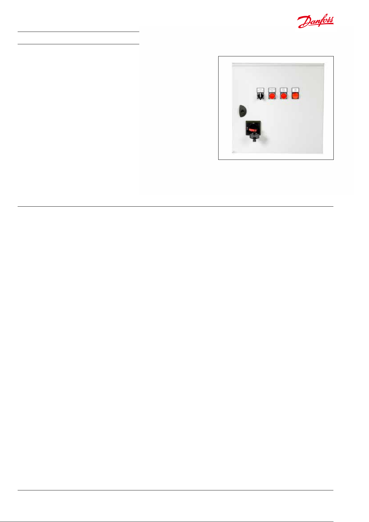
6. Local control panel
7. Options
The Plug & Spray VS units with the Danfoss
FCP 106 Drive Motor are pre-programmed from
the factory. However some parameters must be
adjusted during commissioning (i.e. for the PID
loop).
Danfoss recommends ordering at least one Local
Control Panel (LCP 102) per installation.
For xed installation of the LCP in a cabinet,
Danfoss oers a remote mounting kit with 3 m
cable.
Ordering codes:
VLT® Control Panel LCP 102
(Graphical LCP only): 130B1107
Remote Mounting Kit (LCP 102)
3 m cable, panel mounting bracket,
gasket and fastners: 134B0564
The Plug & Spray product program oers
numerous options and possibilities for customization.
Examples of options:
• Water supply solenoid valve
• Pressure reduction valve (supply)
• Zone or step control valves (please refer to
Danfoss’ wide program of high-pressure
solenoid valves).
For details, please contact your nearest Danfoss
representative.
Multiple valve block solution installed on base frame
AI309730711498en-0 00901 | 02.2021
9
Page 10
Data sheet | Plug & Spray unit NPS
8. Electrical connection
box
The electrical connection box can be directly
connected to a 3×400 V, 50 Hz power supply and
provides a simple, pre-wired “plug and play”
solution for integrating the Plug & Spray unit in a
humidication or adiabatic cooling system. The
electrical connection box is available for CS and
VS units.
The electrical connection box comprises
following basic components:
• Mains disconnect with fuses
• Hand-O-Auto switch (CS only)
• Motor overload protection (CS only)
• Operation hour counter (CS only)
• Inlet pressure monitoring with reset button
• Water temperature monitoring with reset
button
• Terminals for external start signal
(potential free contact)
• Contacts for fault relay
• LCP 102 in front door (VS units only, allows
monitoring operation hours and Hand-OAuto functionality)
10
AI309730711498en-0 00901 | 02.2021
Page 11

Data sheet | Plug & Spray unit NPS
The electrical connection box can be ordered from factory in two versions:
Wall
With 2 metres cable
Free standing
On supports
Ordering codes for any customized units are available on request, please contact your nearest
Danfoss representative.
AI309730711498en-0 00901 | 02.2021
11
Page 12
Danfoss A/S
High Pressure Pumps
Nordborgvej 81
DK-6430 Nordborg
Denmark
© Danfoss | DCS (im) | 2021.02
AI309730711498en-000901 | 12
 Loading...