

Data sheet
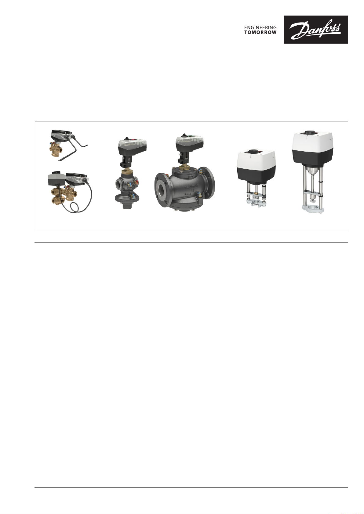
NovoCon® S, M, L and XL
Digital actuators
Novo Con® M Novo Con® LNovo Con® S Novo Con® XL
Table of contents
Description .................................................................................................2
Ordering ......................................................................................................4
Cross reference table AB-QM – Flow sens or - NovoCon® ...6
Technical data ...........................................................................................7
Design ...........................................................................................................9
Installation and orientation .............................................................10
Dip switches ...............................................................................................11
DIP Switch Settings ......................................................................11
DIP Switch Settings - Manual Addressing ........................... 12
Wiring ............................................................................................................13
Wiring considerations.................................................................14
Daisy ch ain & Power booster ............................................................ 18
LED Display ............................................................................................... 22
Application principle ........................................................................... 28
NovoCon® S I/O ............................................................................. 28
NovoCon® I/O and Multiplexers/Relays .............................. 28
Central Plant Changeover – 2 pipe system ....................... 28
ChangeOver6 - 4 pipe system ................................................. 29
ChangeOver6 Energy .................................................................. 29
Analog CO6 mode ....................................................................... 29
ChangeOver6 ................................................................................. 31
No mixing and shut off ....................................................................... 32
Application mode .................................................................................. 32
BACnet objects and Modbus registers usage ......................... 33
Design flow rate set ting ...........................................................33
Advanced configuration and features ................................ 34
Optimize BACnet network speed ..................................................35
Energy management ...........................................................................35
Power Manager ............................................................................ 35
Delta T Manager ........................................................................... 36
Commissioning/connection of flow sensor to: ...................... 38
NovoCon® S .................................................................................... 38
NovoCon® M .................................................................................. 39
NovoCon® L, XL ............................................................................. 40
Auto baud rate ......................................................................................... 41
Auto MAC Addressing - BACnet only ...........................................41
BACnet Obje cts - Analog Value ...................................................... 42
BACnet Obje cts - Multi Stat e Value .............................................. 43
BACnet Objects - Binary Value ........................................................ 45
BACnet Objects- Device Object ...................................................... 45
BACnet Obje cts - Analog Input ....................................................... 46
BACnet Obje cts - Analog Out put ...................................................46
BACnet Objects - Notification class.............................................. 46
BACnet Objects - Averaging ............................................................. 46
BACnet BIBBs serv ices ......................................................................... 46
Modbus registers - Configuration ................................................ 47
Modbus registers - Operating ......................................................... 50
Modbus registers - Information .....................................................51
Alarms & warning ..................................................................................52
Firmware update .................................................................................... 52
Valve Type Selection ............................................................................ 53
Temperature sensors ...........................................................................54
Tender text ................................................................................................54
Trouble shooting ....................................................................................56
Firmware update ......................................................................... 56
BACnet data ................................................................................... 56
Modbus RTU data ........................................................................ 56
Manual operation .................................................................................. 57
Dimensions ............................................................................................... 58
© Danfoss | 2022.01 AI368140926963en-010102 | 1

Data sheet NovoCon® S, M, L and XL Digital actuators
Description
NovoCon® S
NovoCon® S is a high accuracy multi-functional
field bus actuator, specifically designed for use
in combination with the Pressure Independent
Control Valve type AB-QM in sizes from DN 10-32.
The flow is modulated by the AB-QM pressure
independent control valve to avoid overflow and
reduced boiler and/or chiller efficiency.
The actuator with AB-QM is used to control water
supply to fan coil units, chilled beams, induction
units, small re-heaters, re-coolers, AHU’s and other
terminal units for zone control, in which heating/
chilled water is the controlled medium. Due to its
accuracy, remote functionality and flow indication
features, this product facilitates an accelerated
commissioning process, allows easy maintenance,
improves indoor comfort, increases energy savings
and allows for fair cost allocation of heat/cool
energy.
The high position accuracy of the actuator,
together with the pressure independent and linear
characteristic of the AB-QM valve, allow NovoCon®
S to be used as a flow indicator.
Setup of the actuator and valve parameters are
made via fieldbus. Control is achieved via field bus
or via analog inputs to NovoCon® S.
Typical applications are:
• Radiant ceiling panels, supplied by 4 pipes
(Heating supply and return and cooling supply
and return).
• Fan coil units, with single coils supplied by 4
pipes (Heating supply and return and cooling
supply and return).
General features:
• Remote commissioning/Pre-set/Flush features
• Flow, power emission and energy indication
• High position resolution and accuracy
• Energy management algorithms
• 4/2-pipe changeover applications
• I/O applications
• LED bar displaying status and alarms
• No tools required for mounting
• Maintenance-free lifetime
• Self-positioning process
• Low-noise operation
• Plug-in halogen free cables
• Auto MAC addressing for BACnet
• Auto baud rate detection
• Intrinsic alarm reporting for BACnet
• Valve blockage alarm
• Broken wire detection on analog control and
ground signal
• Choice of BACnet MS/TP or Modbus RTU in the
same product
• Mis-wiring protection on any wire up to 30 V
Combined with the Actuator NovoCon®
ChangeOver6, NovoCon® S offers a unique solution
in controlling both the AB-QM valve and a 6-port
motorised ball valve that performs a diverting
function between two water circuits in 4-pipe
changeover systems.
This diverting function, primarily used for radiant
panels, also allows the cooling and heating capacity
of a fan coil unit to be increased for the same
compact size compared to a double coil model
where the heating and cooling water circuits each
have their own coil.
The 6-port diverting valve and actuator work in
combination with an AB-QM PIBCV valve and
NovoCon® S bus actuator. The AB-QM balances the
flow and the NovoCon® S bus actuator controls
the flow. NovoCon® S also controls the 6-port
diverting valve actuator which switches between
heating and cooling. This unique functionality is
characterized by the following:
• There is only one single field bus and power
supply connection cable to the NovoCon® S
actuator. This powers both the NovoCon® S
and controls the 6-port actuator. Furthermore,
there is feedback from the 6-port actuator to
NovoCon® S.
• The NovoCon® S actuator automatically faultdetects, by means of comparing 0-10V control
& feedback signals, if the 6-port actuator is in
manual operation mode, removed from the
valve or if the 6-port valve is blocked.
• The NovoCon® S actuator has two Design Flow
Rate pre-settings: one for heating and another
for cooling.
• The NovoCon® S actuator indicates power
emission and logs energy consumption
for heating and cooling energy based on
flow, supply and return pipe temperature
measurement.
• While in maintenance mode, the 6-port actuator
is able to fully close the valve and prevent any
leakage, thereby saving on stop valves.
• Logic contained within the NovoCon® S actuator,
ensures that only one actuator in each pair
(NovoCon® S and 6-port valve actuator) drives.
This ensures that 2 actuators in the pair never
drive at the same time. This reduces voltage
booster demands in daisy chains.
• The NovoCon® S actuator detects if the 6-port
actuator cable is disconnected. If this is the case
an alarm is initiated.
Features CO6:
• NovoCon® S + ChangeOver6 actuator represents
only ONE device on the fieldbus network
needing no physical I/O
• No cross-flow between heating and cooling
• Simple connection and control
• Feedback for position status and alarms
• Quiet and reliable operation
• Maintenance free
• Teflon seal and polished chrome valve ball to
prevent valve sticking
• Blocked valve alarm
• Manual override
2 | AI368140926963en-010102 © Danfoss | 2022.01

Data sheet NovoCon® S, M, L and XL Digital actuators
Red
AI:2 / 33220
Read / writeable via fieldbus
Read / writeable via fieldbus
AI:2 / 33220
Description (continued)
NovoCon® S (continued)
NovoCon® M
Features Energy:
•
Supply and return temperature measurement
• Power emission indication reading
• Energy management functionality for both
heating and cooling e.g. minimum delta T
management
• Energy logging of both heating and cooling
Features I/O:
• Connect to other devices and present them
on the field bus, e.g. room thermostat,
window contact, CO2 sensor, humidity
sensors, fan control, 0-10V actuator etc.
• Select temperature units, Ohms or use as
BACnet object / Modbus register
Black
Blue
Grey
White
0-20mA
AI:0 / 33216
0-10V
AO:0 / 33286
Yellow
Orange
NovoCon® M is a high accuracy multi-functional
fieldbus actuator, specifically designed for use
in combination with the Pressure Independent
Control Valve type AB-QM NovoCon® in sizes
from DN 40-100 used in air handling units AHU,
chillers and distribution station applications.
The high position accuracy of the actuator,
together with the pressure independent and
linear characteristic of the AB-QM valve, allow
NovoCon® M to be used as a flow indicator.
Setup of the actuator and valve parameters
are made via fieldbus. Control is achieved via
fieldbus or via analog inputs to NovoCon® M.
potential free contacts. Closed circuit <900Ω,
open circuit 100kΩ.
• Available connections: 1 x analog output (V),
1 x analog input (V/mA) and 2 x resistance
based inputs (°C/°F/Ohms)
BACnet object / Modbus register
0-10V
0-10V
0-10V
AI:1 / 33218
10kΩ
10kΩ
0-20mA
AI:0 / 33216
0-10V
AO:0 / 33286
AI:1 / 33218
General features:
• Remote commissioning/Pre-set/Flush features
• Flow, power emission and energy indication
• High position resolution and accuracy
• Energy management algorithms
• Inputs/Outputs
- 3x Resistance Inputs (Pt1000, PT500, PT100,
NTC 10k Type 2 & 3)
- 1x Analog Input (0-10V or 0/4-20mA),
- 1x Analog Output (0-10V)
• LED displaying status and alarms
• No tools required for mounting on valve
• Maintenance-free lifetime
• Low-noise operation
• Auto MAC addressing for BACnet
• Auto baud rate detection
• Intrinsic alarm reporting for BACnet
• Valve blockage alarm
• Choice of BACnet MS/TP or Modbus RTU in
the same product
• Mis-wiring protection on any wire up to 30 V
NovoCon® L, XL NovoCon® L/XL is a high accuracy multi-
functional fieldbus actuator, specifically
designed for use in combination with the
Pressure Independent Control Valve type AB-QM
in sizes from DN 125-250 used in air handling
units AHU, chillers and distribution station
applications.
The high position accuracy of the actuator,
together with the pressure independent and
linear characteristic of the AB-QM valve, allow
NovoCon® L/XL to be used as a flow indicator.
Setup of the actuator and valve parameters
are made via fieldbus. Control is achieved via
fieldbus or via analog inputs to NovoCon® L/XL.
General features:
• Remote commissioning/Pre-set/Flush features
• Flow, power emission and energy indication
• High position resolution and accuracy
• Energy management algorithms
• Inputs/Outputs
- 3x Resistance Inputs (Pt1000, PT500, PT100,
NTC 10k Type 2 & 3)
- 1x Analog Input (0-10V or 0/4-20mA),
- 1x Analog Output (0-10V)
• LED displaying status and alarms
• Maintenance-free lifetime
• Low-noise operation
• Auto MAC addressing for BACnet
• Auto baud rate detection
• Intrinsic alarm reporting for BACnet
• Valve blockage alarm
• Choice of BACnet MS/TP or Modbus RTU in
the same product
• Mis-wiring protection on any wire up to 30 V
AI368140926963en-010102 | 3© Danfoss | 2022.01
Data sheet NovoCon® S, M, L and XL Digital actuators
Ordering
NovoCon® S
Typ e Code No.
NovoCon® S 003Z8504
Accessories
Typ e Length Connections Cable material Code No.
Cable NovoCon® Digital 1.5 m bus / power Halogen free 003Z8600
Cable NovoCon® Digital 5 m bus / power Halogen free 003Z8601
Cable NovoCon® Digital 10 m bus / power Halogen free 003Z8602
Cable NovoCon® Digital, daisy chain
Cable NovoCon® Digital, daisy chain
Cable NovoCon® Digital, daisy chain
Cable NovoCon® Digital, daisy chain
Cable NovoCon® Analog 1.5 m 0-10 V / power / voltage booster Halogen free 003Z8606
Cable NovoCon® Analog 5 m 0-10 V / power / voltage booster Halogen free 003Z8607
Cable NovoCon® Analog 10 m 0-10 V / power / voltage booster Halogen free 003Z8608
Cable NovoCon® I/O 1.5 m actuator / free wires Halogen free 003Z8612
Note! Cables are not i ncluded with actuator and m ust be ordered separately.
Cable NovoCon®
Energy
Cable NovoCon®
Energy
Cable NovoCon®
Temperature I/O
Note! If se parate Pt1000 temperature sensors a re needed, Danfoss has an ar ray of Pt100 0 sensors that can be used with Novo Con® S.
See Danfoss P t1000 sensor s ESMT, ESM-10, ESM-11, ESMB-12, ESMC, ESMU and code n o. 187F3418.
1.5 m Plug-in cable with Pt1000 surface temperature sensors PVC 003Z8610
1.5 m
1 m / Temp.
sensor 1.5m
0.5 m actuator / actuator Halogen free 003Z8609
1.5 m actuator / actuator Halogen free 003Z8603
5 m actuator / actuator Halogen free 003Z8604
10 m actuator / actuator Halogen free 003Z8605
Plug-in cable with Pt1000 Immersed /universal
temperature sensors (Ø 5,8m m)
Plug-in cable with Pt1000 surface temperature sensors
and free wires for input, output and power
PVC 003Z8611
Halogen free.
Sensor cables PVC
003Z8613
ChangeOver6 actuators
Actuator NovoCon ChangeOver
Actuator NovoCon ChangeOver6 Energy
Actuator NovoCon ChangeOver6 Flexible
6
1 m Plug-in Halogen free 003Z 8520
1 m
Temp. sensor 1.5 m
1.5 m
Plug-in incl. Pt1000 sur face
temperature sensors
Actuator / open wires Halogen free 003Z8522
Halogen free
Sensor cables PVC
003 Z8521
Typ e DN Fire load class Code No.
ChangeOver6 insulation
According to D/N 4102
Typ e DN
ChangeOver6 valve
15 B2 003Z3159
k
VS
Connection
(m3/h)
15 2.4 Rp ½ 003 Z3150
20 4.0 Rp ¾ 0 03Z3151
Code No.
NovoCon® Configuration Tool
Typ e
NovoCon® Configuration Tool cable 5 m
Length
Connections Cable material Code No.
USB /
actuator
Software available on www.novocon.com
Temperature sensors
Typ e
Immersed Pt 1000 / f 5.2 mm / 1.5 m cable,
pair, MID
Code No.
187F3 418
Service kit - combination with old AB-QM
Typ e Code No.
NovoCon® adapter for AB-QM, DN 10-32 (5 pcs.) 003Z0239
Accessories (Cable NovoCon® Energy)
Typ e Designation Code No.
Immersion brass pockets,
40 mm, Ø 6.0 pair.
Pockets for Cable
NovoCon® Energy
(003Z8611)
Halogen free. USB Conver ter, PVC 003Z8620
For pipes DN25/32.
Immersion brasspockets, 35 mm, Ø 5.2
pair, MID. For pipes
DN15 -32
087G6061
087G6053
4 | AI368140926963en-010102 © Danfoss | 2022.01
Data sheet NovoCon® S, M, L and XL Digital actuators
Ordering (continued) Actuator
NovoCon® M
Typ e Supply voltage Code No.
NovoCon® M 24V ac /dc 003Z8540
Temperature sensors
Typ e Code No.
Immersed Pt 1000 / Ø 5.2 mm / 1.5 m cable,
pair, MID
Immersed Pt 1000 / Ø 5.2 mm / 3.0 m cable,
pair, MID
Accessories
Designation Code No.
Immersion brass-pockets, 52 mm, Ø 5.2 pair,
MID. For pipes DN40-65
Immersion brass-pockets, 85 mm, Ø 5.2 pair,
MID. For pipes DN80-125
NovoCon® Configuration Tool
Typ e Length Connections Cable material Code No.
NovoCon® Configuration Tool cable 5 m USB / actuator Halogen free. USB Converter, PVC
Software available on www.novocon.com
NovoCon® L, XL
Actuators
Picture Ty pe
Temperature sensors
Typ e
Immersed Pt 1000 / Ø 5.2 mm / 3.0 m cable,
pair, MID
Valve t ype
NovoCon® L AB -QM D N125-150
NovoCon® L SU AB -QM D N125-150
NovoCon® L SD AB -QM D N125-150
NovoCon® XL AB- QM DN2 00-250
187F3 418
187F3419
087G6054
087G6055
Code No.
003Z8560
003Z8 561
003Z8562
003Z8563
Code No.
187F3419
Valves
Typ e Co de No.
AB-QM NovoCon DN40 PN16 3TP 0 03Z17 70
AB-QM NovoCon DN50 PN16 3TP 00 3Z1771
AB-QM NovoCon DN50 PN16 - Flange 3TP 00 3Z177 2
AB-QM NovoCon DN65 PN16 3TP 0 03Z17 73
AB-QM NovoCon DN65 PN16 3TP HF 00 3Z179 3
AB-QM NovoCon DN80 PN16 3TP 0 03Z17 74
AB-QM NovoCon DN80 PN16 3TP HF 00 3Z179 4
AB-QM NovoCon DN100 PN16 3TP 003 Z1775
AB-QM NovoCon DN100 PN16 3TP HF 00 3Z179 5
Note: The abo ve AB-QM NovoCo n valves must be used with N ovoCon® M.
003Z8620
Accessories
Designation Co de No.
Immersion brass-pockets, 85 mm, Ø 5.2 pair,
MID. For pipes DN80-125
Immersion brass-pockets, 120 mm, Ø 5.2 pair,
MID. For pipes DN150-200
Immersion stainless steel-pockets, 155mm,
Ø
5.2 pair, MID. For pipes DN250
087G6055
087G6056
087G6059
NovoCon® Configuration Tool
Typ e Length Connections Cable material Code No.
NovoCon®
Configuration Tool cable
Software available on www.novocon.com
5 m USB / actuator Halogen free. USB Converter, PVC 003Z8620
AI368140926963en-010102 | 5© Danfoss | 2022.01

Data sheet NovoCon® S, M, L and XL Digital actuators
Cross reference table AB-QM – Flow sensor - NovoCon®:
Valve
code
003Z8220
003Z 8221
003Z8222
003Z8223
003Z8224
003Z8320
003Z8321
003Z8322
003Z8323
003Z8324
003 Z1204
003 Z1224
003 Z1205
003 Z1225
00 3Z1770
00 3Z1771
003Z1773
00 3Z1793
00 3Z1774
00 3Z179 4
00 3Z1775
003Z1795
003Z0705
003 Z0715
003Z0706
003 Z0716
003Z0707
00 3Z0717
003Z0708
003 Z0718
Valve name
AB-Q M4 DN15 LF 0. 2 m3/h
AB-Q M4 DN15 0.65 m3/h
AB-Q M4 DN15 HF 1.2 m3/h
AB-Q M4 DN20 1.1 m3/h
AB-Q M4 DN20 HF 1.9 m3/h
AB-Q M4 DN15 LF 0. 2 m3/h
AB-Q M4 DN15 0.65 m3/h
AB-Q M4 DN15 HF 1.2 m3/h
AB-Q M4 DN20 1.1 m3/h
AB-Q M4 DN20 HF 1.9 m3/h
AB-Q M DN25 1.7 m3/h
AB-Q M DN25 HF 2.7 m3/h
AB-Q M DN32 3.2 m3/h
AB-Q M DN32 HF 4.0 m3/h
AB-Q M NovoCon DN40
7. 5 m3/h
AB-Q M NovoCon DN50
12. 5 m3/h
AB-Q M NovoCon DN65
20.0 m3/h
AB-Q M NovoCon DN65 HF
25.0 m3/h
AB-Q M NovoCon DN80
28.0 m3/h
AB-Q M NovoCon DN80 HF
40.0 m3/h
AB-Q M NovoCon DN100
38.0 m3/h
AB-Q M NovoCon DN100 HF
59.0 m3/h
AB-Q M DN125 90.0 m3/h
AB-Q M DN125 HF 110.0 m3/h
AB-Q M DN150 150.0 m3/h
AB-Q M DN150 HF 190.0 m3/h
AB-Q M DN200 220.0 m3/h
AB-Q M DN200 HF 285.0 m3/h
AB-Q M DN250 300.0 m3/h flange 003Z8563 NovoCo n XL 187F3532 SONO 3500 CT D N150 Qp 150.0 m3/h flange / 187F3419 087G6059
AB-Q M DN250 HF 370.0 m3/h flange 003Z8563 Novo Con XL 187F3532 SONO 3500 CT D N150 Qp 150.0 m3/h flange / 187F3419 087G6059
* IO cable with sur face sensor (Pt1000)
Valve
connection
thread 003Z850 4 NovoCon S 187F3771 Sono S30 DN15 Qp 0.6 m3/ h thread
thread 003Z850 4 NovoCon S 187F3771 Sono S30 DN15 Qp 0.6 m3/ h thread
thread 003Z850 4 NovoCon S 187F3772 Sono S30 D N15 Qp 1.5 m3/h thread
thread 003Z850 4 NovoCon S 187F3772 Sono S30 D N15 Qp 1.5 m3/h thread
thread 003Z850 4 NovoCon S
int. thread 003Z8504 Novo Con S 187F3771 Sono S30 DN15 Qp 0.6 m3/h thread
int. thread 003Z8504 Novo Con S 187F3771 Sono S30 DN15 Qp 0.6 m3/h thread
int. thread 003Z8504 Novo Con S 187F3772 Sono S30 DN15 Qp 1.5 m3/h thread
int. thread 003Z8504 Novo Con S 187F3772 Sono S30 DN15 Qp 1.5 m3/h thread
int. thread 003Z8504 Novo Con S 187F3772 Sono S30 DN15 Qp 1.5 m3/h thread
thread 003Z850 4 NovoCon S 187F3773 Sono S30 DN20 Qp 2. 5 m3/h thread
thread 003Z850 4 NovoCon S 187F3773 Sono S30 DN20 Qp 2. 5 m3/h thread
thread 003Z850 4 NovoCon S 187F3774 Sono S30 DN25 Qp 3. 5 m3/h thread
thread 003Z850 4 NovoCon S 187F3774 Sono S30 DN25 Qp 3. 5 m3/h thread
thread 003Z854 0 NovoCon M 187F3776 Sono S30 DN4 0 Qp 10.0 m3/h thread / 187 F3418 087G6054
thread 003Z854 0 NovoCon M 187F3776 Sono S30 DN4 0 Qp 10.0 m3/h thread / 187 F3418 087G6054
flange 0 03Z8540 Novo Con M 187F3777 Sono S 30 DN50 Qp 15.0 m3/h f lange / 187F3419 087G6054
flange 0 03Z8540 Novo Con M 187F3778 Sono S30 DN 65 Qp 25.0 m3/h f lange / 187F3419 087G6054
flange 0 03Z8540 Novo Con M 187F3778 Sono S30 DN 65 Qp 25.0 m3/h f lange / 187F3419 087G6055
flange 0 03Z8540 Novo Con M 187F3779 Sono S30 DN8 0 Qp 40.0 m3/h f lange / 187F3419 087G6055
flange 0 03Z8540 Novo Con M 187F3779 Sono S30 DN8 0 Qp 40.0 m3/h f lange / 187F3419 087G6055
flange 0 03Z8540 Novo Con M 187F3780 Sono S30 D N100 Qp 6 0.0 m3/h f lange / 187F3419 087G6055
flange 0 03Z8560 NovoCon L 187F3530 S ONO 3500 CT DN100 Qp 60.0 m 3/h flange / 187F3419 087G6055
flange 0 03Z8560 NovoCon L 187F3530 S ONO 3500 CT DN100 Qp 60.0 m 3/h flange / 187F3419 087G6055
flange 0 03Z8560 NovoCon L 187F3531 SONO 350 0 CT DN125 Qp 100.0 m3/h flange / 187F3419 087G6056
flange 0 03Z8560 NovoCon L 187F3531 SONO 350 0 CT DN125 Qp 100.0 m3/h flange / 187F3419 087G6056
flange 003Z8563 NovoCon XL 187F3531 SONO 3500 CT D N125 Qp 100.0 m3/ h f lange / 187F3419 087G6056
flange 003Z8563 NovoCon XL 187F3532 SONO 3500 C T DN150 Qp 150.0 m 3/h flange / 187F3419 087G6056
Actuator
code
Actuator
name
Flow
sensor
code
187F3772 Sono S30 DN15 Qp 1.5 m3/h thread
Flow sensor name
Flow
sensor
connection
cable
Temperature
sensor code
(Pt1000)
Immersion
pockets code
NovoCon S
003Z8613* / /
003Z8612 187F3 418 087G6053
003Z8613* / /
003Z8612 187F3 418 087G6053
003Z8613* / /
003Z8612 187F3 418 087G6053
003Z8613* / /
003Z8612 187F3 418 087G6053
003Z8613* / /
003Z8612 187F3 418 087G6053
003Z8613* / /
003Z8612 187F3 418 087G6053
003Z8613* / /
003Z8612 187F3 418 087G6053
003Z8613* / /
003Z8612 187F3 418 087G6053
003Z8613* / /
003Z8612 187F3 418 087G6053
003Z8613* / /
003Z8612 187F3 418 087G6053
003Z8613* / /
003Z8612 187F3 418 087G6053
003Z8613* / /
003Z8612 187F3 418 087G6053
003Z8613* / /
003Z8612 187F3 418 087G6053
003Z8613* / /
003Z8612 187F3 418 087G6053
6 | AI368140926963en-010102 © Danfoss | 2022.01
Data sheet NovoCon® S, M, L and XL Digital actuators
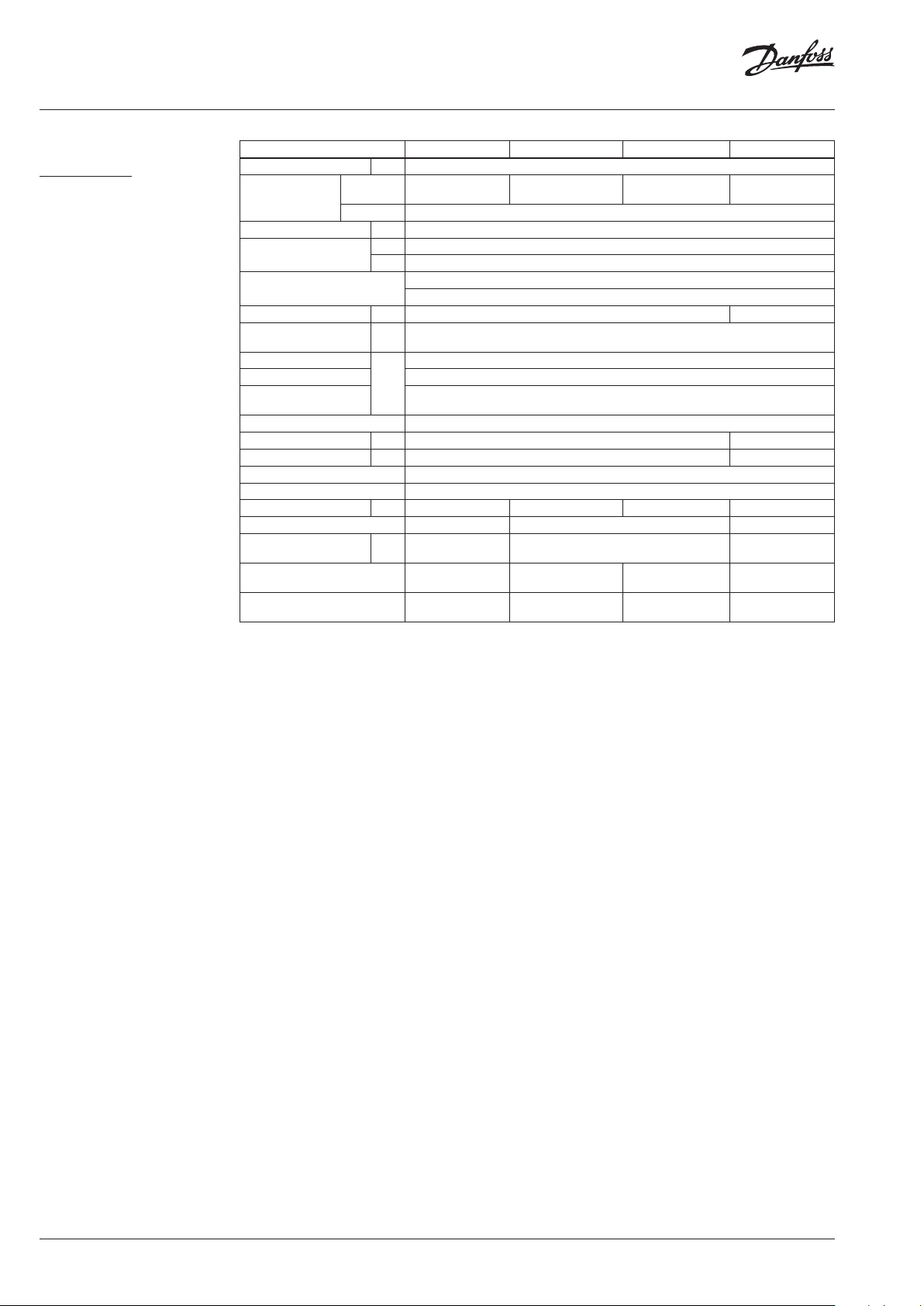
Technical data
NovoCon® S
Power supply range 24 V AC/DC, 50 / 60 Hz *
Power consumption
Protection class III safet y extra-low voltage
Control signal NovoCon® S
Impedance
Actuator sp eed selections (o pen to close)
Stroke 7 mm
Force 90 N
Position accuracy ± 0.05 mm
Ambient temp. range −10° C to 50° C
Ambient humidity 98% r.h., non-condensing (accordin g to EN 60730 -1)
Max. medium temp. 120 ° C
Storage temp. range –40 to 70 °C
Grade of enclosure IP 54 (IP 40 upside down)
Weight 0.4 kg
* NovoCon® S is designe d to operate at power deviatio ns up to ±25%.
0-10 VDC, 0-5 VDC, 2-10 VDC, 5-10 VDC, 2- 6 VDC, 6-10 VDC, 0-20 mA, 4 -20 mA
Operating: 2.7 VA@24VAC / 1.2 W@24VDC
Standby: 1.8 VA@24VAC / 0.7 W@24VDC
BACnet MS/TP, Modbus RTU
Rin AI:0 >100 kΩ (V); 500 Ω (mA)
Rout AO: 1500 Ω
3 sec/mm, 6 sec/mm, 12 sec/mm, 24 sec/mm, Constant Time
BACnet data
Typ e Description
BACnet device profile BACnet Application Specific Controller (B -ASC)
BACnet protocol BACnet Master Slave / Token Passing (MS/TP)
BACnet baud rates supported
Auto baud rate detection* / 9600 bps / 19200 bps / 38400 bps / 56700 bps / 76800 bps / 115200bps
Modbus RTU data
Supported baud rates
Supported transmission
modes
* Default
Auto baud rate detection* / 9600 bps / 19200 bps / 38400 bps / 56700 bps / 76800 bps / 115200bps
Parity: None (1-8-N -2) / Odd (1-8- O-1) / Even (1-8-E-1) / None (1-8-N-1) / Auto parity*
Data format: Parity (Start bit - Data bits - Parity - Stop bits)
NovoCon® M
Power supply V 24 ±25% ac/dc
Power consumption
Frequency Hz 50 /60±10 %
Control signal
Impedance
Closing force N 550
Max. stroke mm 20
Position accuracy mm ± 0.2
Actuator sp eed selections (open to
close)
Max. medium temperature
Ambient temperature –10 … 50
Storage and transport temperature –40 … 70
Ambient humidity 5-95% r.h., non-condensing (according to EN 60730-1)
Protection class III
Grade of enclosure IP 54
Weight kg 0.5
running VA <3.5@24Va c / <2.0@24Vdc
standby W 2.0 ac / 0.9 dc
VDC BACnet MS/TP, Modbus RTU, 0-10, 0-5, 2-10, 5-10, 2-6, 6-10
mA 0-20, 4 -20
Rin 90k Ω (V). 500 Ω (mA)
Rout 250Ω
s/mm 3, 6, 12, 24, Constant Time
120
°C
AI368140926963en-010102 | 7© Danfoss | 2022.01
Data sheet NovoCon® S, M, L and XL Digital actuators
Technical data (continued)
NovoCon® L, XL
Actuator type NovoCon® L NovoCon® L SD NovoCon® L SU Novo Con® XL
Power supply V 24; +10 … 15 %; AC/DC
Power consumption
Frequency Hz 50/60
Control signal
Impedance
Position accuracy mm ± 1 ± 1.8
Actuator speed selections
(open to close)
Max. medium temperature
Ambient temperature –10 … 50
Storage and transport
temperature
Ambient humidity 5-95% r.h., non-condensing (according to EN 60730-1)
Closing force N 2000 4000
Max. stroke mm 50 80
Protection class III
Grade of enclosure IP 54
Weight kg 5.4 9.6 8.9 6.3
Safety function - Yes -
Safety function runtime /
32 mm stroke
Manual operation
Power failure response
Operating:
Standby: 1.7VA@24VAC / 0 .7W@24V DC
9.6VA@24VAC /
7.2W@24VDC
Vdc BACnet MS/TP, Modbus RTU, 0 -10, 0-5, 2-10, 5-10, 2-6, 6-10
mA 0-20, 4 -20
s/
mm
°C
s - 120 -
Electrical and
mechanical
Stem remains in last
position
14.4VA@24VAC /
12W@24VDC
Rin 90k Ω (V). 500 Ω (mA)
3, 6, 12, 24, Constant Time
–40 … 70 (above 50°C, less than 3 days)
Electrical and
mechanical
Safety function Down,
pushes stem down
14.4VA@24VAC /
12W@24VDC
Rout 250Ω
120
Electrical and
mechanical
Safety function
Open, pulls stem up
13.9VA @24VAC /
10.8W@24VD C
Electrical and
mechanical
Stem remains in last
position
8 | AI368140926963en-010102 © Danfoss | 2022.01

Data sheet NovoCon® S, M, L and XL Digital actuators
Design
NovoCon® S
NovoCon® M
⑦
⑥
⑤
①
②
③
④
1. Removable lid
2. Bus and power connections
3. Status LED
4. Locking ring
5. Manual override
6. Reset button
7. DIP switches
1. Communication LED
2. Manual operation knob
3. Buttons and status LED
4. Valve connector
5. Position indicator
6. DIP switches (under cover)
7. Service cover
8. Removable gland support
NovoCon® L, XL
1. Manual operation knob
2. Buttons and status LED
3. Service cover
4. Removable gland support
5. End position indication ring
6. Stem connector
7. Valve connector
AI368140926963en-010102 | 9© Danfoss | 2022.01
Data sheet NovoCon® S, M, L and XL Digital actuators
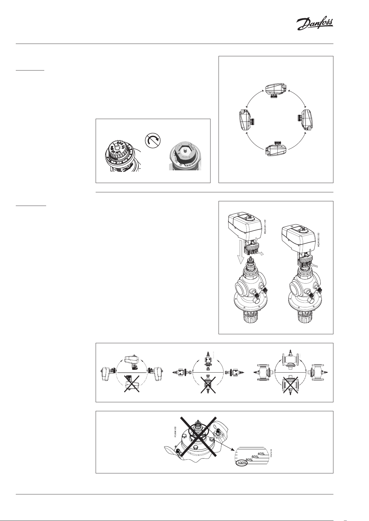
Installation and orientation NovoCon® S can be mounted in any position.
NovoCon® S
However, mounting orientation affects the IP
classification. Using NovoCon® S upside down in
cooling applications is not recommend due to
the risk condensation brings. See illustration.
Note!
IP classification is only valid when cable or plugs are
present in all connections.
IP 54
IP 54
No presetting should be done
on AB-QM valves. Valve must
be set to full open
(10 = AB-QM 4.0, 100% =
AB-QM)
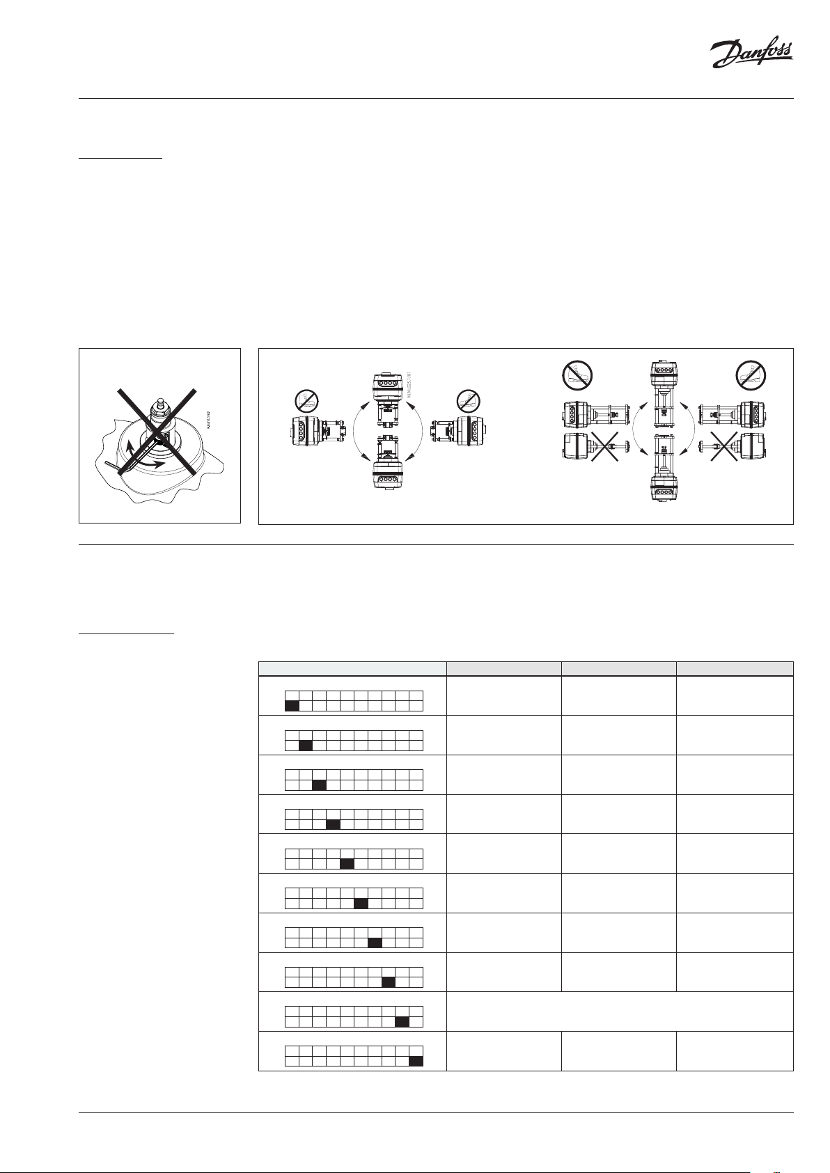
NovoCon® M
DN 15 - 32
DN 15, 20
0 - 10
No tool is required to mount the actuator on the
valve. Installation of the valve with the actuator
is allowed in the horizontal position or upwards.
Installation downwards is not allowed.
The actuator must not be installed in an
explosive atmosphere, at ambient temperature
lower than 0 °C or at ambient temperature higher
than 50 °C. It must not be subject to steam jets,
water jets or dripping liquid.
Note: The actuator may be rotated up to 360°
with respect to the valve stem by loosening the
retaining fixture. Once the actuator is in place,
retighten the retaining fixture.
Note: The cable and cable gland/grommet used,
must not compromise the actuator’s IP rating.
There must be no strain on the connectors.
The rubber cable grommet delivered from
factory do not compromise the IP rating but do
not provide full strain relief according to the LVD
directive.
Please observe local rules and regulations.
NO presetting!
DN 25, 32
0 - 100 %
③
IP 54
IP 40
①
②
⑤
④
DN 40 - 100
NO presetting!
100 %
10 | AI368140926963en-010102 © Danfoss | 2022.01
Data sheet NovoCon® S, M, L and XL Digital actuators
Installation (continued)
NovoCon® L, XL
DN 125 - 250
NO presetting!
–
+
100 %
Mechanical
Please check the allowed installation positions
for the valve and actuator. The actuator can be
installed in all positions (see below).
Installation of the actuator assembly is certified
for placement within the plenum airspace.
Use a M8/SW13 key (not supplied) to fit the
actuator to the valve body. Allow for necessary
clearance for maintenance purposes. To link
valve and actuator stems use a 4mm Allen
key (not supplied). The actuator has position
indication rings which should be pushed
together before el. connection; after calibration
cycle they indicate end positions of the stroke.
NovoCon® L NovoCon® XL
Electrical connection
Electrical connections can be accessed by
removing the service cover.
NovoCon® L/XL
Four cable entries are provided
- (1) M16x1.5
- (2) M20x1.5
- (1) 1/2”
Note in order to maintain the enclosure’s rating
appropriate electrical conduit connectors must
be installed.
Please observe local rules and regulations.
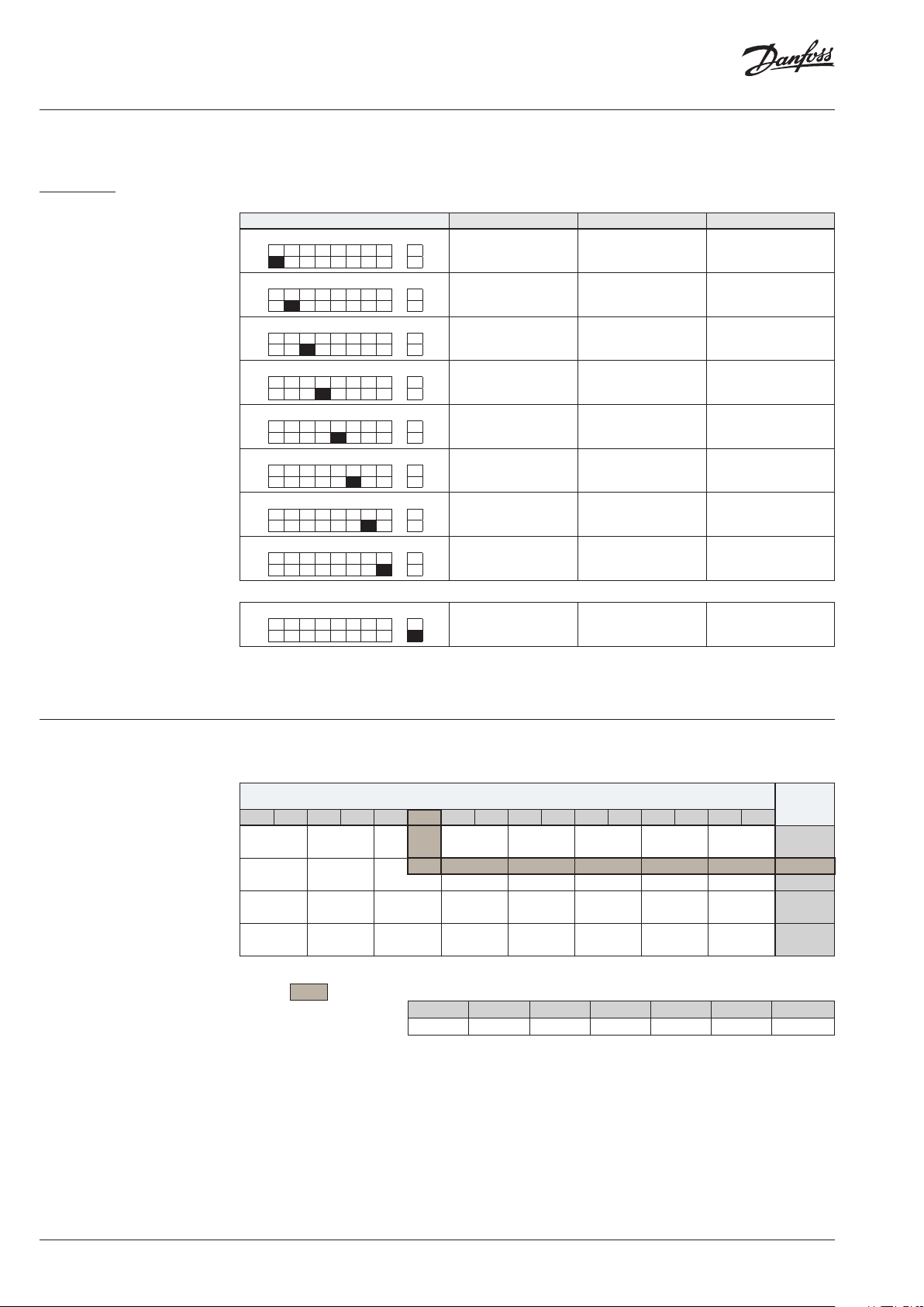
Dip switches
DIP Switch Settings
NovoCon® S, L, XL
The DIP switches located under the housing cover are for manual addressing.
The jumper next to the connectors is used for terminal resistor setting.
BACnet: Auto MAC addressing is default. For manual MAC addressing, use DIP Switches.
Modbus: Manual MAC addressing is default. Automatic addressing is not available for Modbus.
However, if an address has been assigned in BACnet before switching to Modbus, the
address will also be used in Modbus if the DIP switches are left in the default positions.
DIP Switch Configuration name OFF state (default) ON state
1 2 3 4 5 6 7 8 9 10
1.
1 2 3 4 5 6 7 8 9 10
2.
1 2 3 4 5 6 7 8 9 10
3.
1 2 3 4 5 6 7 8 9 10
4.
1 2 3 4 5 6 7 8 9 10
5.
1 2 3 4 5 6 7 8 9 10
6.
1 2 3 4 5 6 7 8 9 10
7.
1 2 3 4 5 6 7 8 9 10
8.
1 2 3 4 5 6 7 8 9 10
9.
1 2 3 4 5 6 7 8 9 10
10.
The actuato r possesses a resistor, DIP switch no. 8, th at can be activated in the last ac tuator on the bus for correct te rmination of the bus.
When the protocol is ch anged on DIP switch no. 10, a power c ycle is required to make the actu ator adopt the newly selec ted protocol.
BACnet addr ess / Modbus
ON
OFF
ON
OFF
ON
OFF
ON
OFF
ON
OFF
ON
OFF
ON
OFF
ON
OFF
ON
OFF
ON
OFF
unit ID bit 0
BACnet addr ess / Modbus
unit ID bit 1
BACnet addr ess / Modbus
unit ID bit 2
BACnet addr ess / Modbus
unit ID bit 3
BACnet addr ess / Modbus
unit ID bit 4
BACnet addr ess / Modbus
unit ID bit 5
BACnet addr ess / Modbus
unit ID bit 6
Termination r esistor (120Ω)
Logic ‘0’ Logic ‘1’
Logic ‘0’ Logic ‘1’
Logic ‘0’ Logic ‘1’
Logic ‘0’ Logic ‘1’
Logic ‘0’ Logic ‘1’
Logic ‘0’ Logic ‘1’
Logic ‘0’ Logic ‘1’
No
termination
Not used
- BACnet M S/TP Modbus R TU
Termination resistor enabled
AI368140926963en-010102 | 11© Danfoss | 2022.01
Data sheet NovoCon® S, M, L and XL Digital actuators
DIP Switch Settings
(continued)
NovoCon® M
BACnet: Auto MAC addressing is default. For manual MAC addressing, use DIP switches
Modbus: Manual MAC addressing is default. Automatic addressing is not available for Modbus.
However, if an address has been assigned in BACnet before switching to Modbus, the
address will also be used in Modbus if the DIP switches are left in the default positions.
DIP Switch Configuration name OFF state (default) O N state
1 2 3 4 5 6 7 8 R
1.
1 2 3 4 5 6 7 8 R
2.
1 2 3 4 5 6 7 8 R
3.
1 2 3 4 5 6 7 8 R
4.
1 2 3 4 5 6 7 8 R
5.
1 2 3 4 5 6 7 8 R
6.
1 2 3 4 5 6 7 8 R
7.
1 2 3 4 5 6 7 8 R
8.
BACnet addr ess / Modbus
ON
OFF
BACnet addr ess / Modbus
ON
OFF
BACnet addr ess / Modbus
ON
OFF
BACnet addr ess / Modbus
ON
OFF
BACnet addr ess / Modbus
ON
OFF
BACnet addr ess / Modbus
ON
OFF
BACnet addr ess / Modbus
ON
OFF
ON
OFF
unit ID bit 0
unit ID bit 1
unit ID bit 2
unit ID bit 3
unit ID bit 4
unit ID bit 5
unit ID bit 6
- BACn et MS/TP Modbus RT U
Logic ‘0’ Logic ‘1’
Logic ‘0’ Logic ‘1’
Logic ‘0’ Logic ‘1’
Logic ‘0’ Logic ‘1’
Logic ‘0’ Logic ‘1’
Logic ‘0’ Logic ‘1’
Logic ‘0’ Logic ‘1’
DIP Switch Settings
- Manual Addressing
1 2 3 4 5 6 7 8 R
R.
ON
Termination r esistor (120Ω) No termination
OFF
Termination r esistor enable d
The actuator p ossesses a resistor, located betwe en the connectors, DIP s witch no. 9 R on/off, that can be activate d in the last actuator
on the bus for corre ct termination of the bus .
When the protocol is ch anged on DIP switch no. 8, a po wer cycle is required to make th e actuator adopt the newl y selected protocol.
BACnet MAC address/Modbus Slave ID is set by DIP switch 1 to 7.
0 = OFF, 1 = ON
DIP switch
1, 2, 3, 4
0000 1000 0100 110 0 0 010 1010 011 0 111 0 0001 1001 0101 11 01 0 011 1011 0111 1111
0* 1 2 3 4
16 17 18 19 20
32 33 34 35
48 49 50 51 52
64 65 66 67 68 69 70 71 72 73 74 75 76 77 78 79 001
80 81 82 83 84 85 86 87 88 89 90 91 92 93 94 95 101
96 97 98 99 100 101 102 103 10 4 105 106 107 10 8 109 110 111 011
112 113 114 115 116 117 118 11 9 120 121 122 123 12 4 12 5 126 127 * 111
5
6 7 8 9 10 11 12 13 14 15 000
21
22 23 24 25 26 27 28 29 30
36 37 38 39 40 41
53
54 55 56 57 58 59 60 61 62
42 43 44 45 46
* Addresses no. 0 and 127 must not be used.
Example
Setting MAC address to 37:
DIP 1 D IP 2 D IP 3 D IP 4 DIP 5 DI P 6 DI P 7
ON OFF ON OFF OFF ON OFF
DIP switch
5,6,7
31 100
47 010
63 110
12 | AI368140926963en-010102 © Danfoss | 2022.01

Data sheet NovoCon® S, M, L and XL Digital actuators
Wiring
NovoCon® S
The wiring of BACnet MS/TP or Modbus RTU
(RS485) must be carried out in accordance with
applicable standard ANSI/TIA/EIA-485-A-1998.
Digital port
Galvanic separation shall be provided for
segments crossing buildings.
Common ground shall be used for all devices
Multifunctional
port
on the same network inclusive router,
gateways etc.
Digital port
All bus connections in the cables are made with
twisted wires.
The cable type used for NovoCon® analog, digital and I/O cables is AWG22/0.32mm2.
If other cables are used to extend the length, always use twisted pair wire for bus signal and include
ground for the bus signal. The recommended cable type is AWG22/0.32 mm2. If used for longer
distances please use a AWG20/0.5mm2 or AWG18/0.75mm2 cable. The cable’s impedance characteristic
shall be between 100-130Ω. The capacitance between conductors shall be less than 100 pf per meter.
The length of the cables influence on the communication speed. Longer cable lengths should result in
lower baud rates. The total maximum cable length allowed per network is 1200m.
Use a minimum 20 cm distance between 110V/230V/400V power line cables and bus cables.
NovoCon® S has mis-wiring protection on up to 30 V AC/DC on all wires, but be aware that if 30V AC
are connected to the Analog input, the external power supply will see this as a short circuit and blow
the fuse in the external power supply.
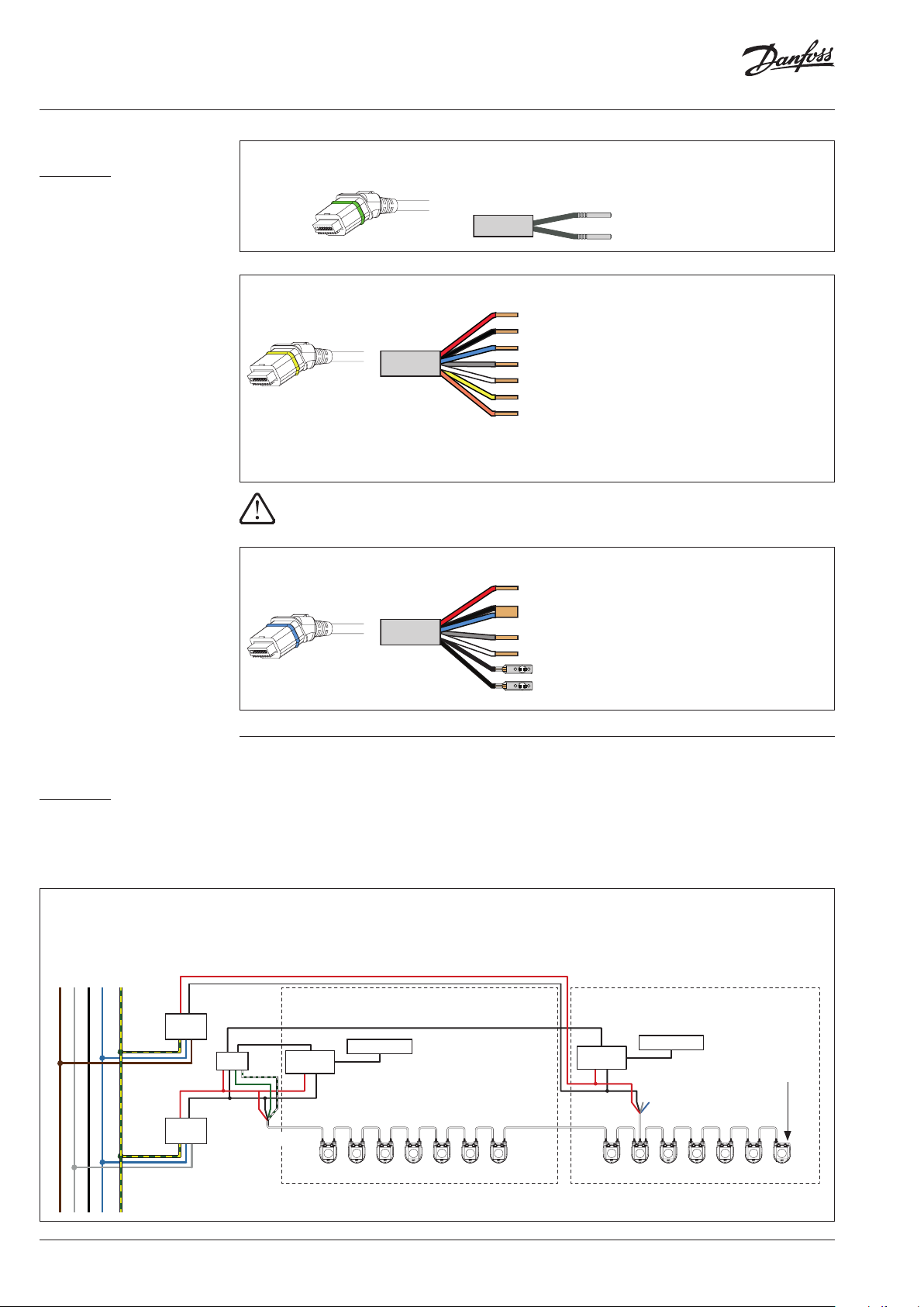
NovoCon® digital daisy chain cable
Black O-ring
Black O-ring
The digital daisy chain cable is used to connect power and BACnet/Modbus between two
NovoCon® S devices.
NovoCon® digital cable
Red: Power
White O-ring
Common ground for power
Black:
and bus signal wire
Green: ‘+’ non-inverting signal wire
Green/
‘-‘ inverting signal wire
White:
The digital cable is used to connect NovoCon® to other BACnet/Modbus devices. It is also used to
connect NovoCon to a longer length of power/communication cable other than standard sales codes.
NovoCon® analog cable
Red O-ring
The analog cable is used to connect power and analog control signal.
The analog cable can also be used as a voltage booster for NovoCon® S on the network.
Red: Power
Black: Power ground
Grey: Analog input
Blue: Analog input ground
Cable NovoCon® Energy with Pt1000 surface sensor
NovoCon® Energy cable - Pt1000 surface sensors
Green O-ring
AI368140926963en-010102 | 13© Danfoss | 2022.01
Data sheet NovoCon® S, M, L and XL Digital actuators
Wiring (continued)
NovoCon® S (continued)
Cable NovoCon® Energy with universal Pt1000 temperature sensor
NovoCon® Energy cable - Pt1000 immersed sensors
Green O-ring
Cable NovoCon® I/O
Red Power 24V (in/out)
Black
Blue
Power ground (in/out)
Ground T1, T2, V/mA input & V output signal
Grey V/mA input signal
Yellow O-ring
White V output signal
Yellow T1 or resistance input
Orange T2 or resistance input
The red and black wires can be used to boost the power on the line. They may also be used to power
external devices, a separate calculation must be made for available power.
To avoid electrical short-circuiting, ensure that loose cable-ends have been connected or
isolated before inserting the plug-in connector to the NovoCon® S actuator.
Cable NovoCon® Temperature I/O
Red Power 24V (in/out)
Black
Power ground (in/out)
Blue
Ground T1, T2, V/mA input & V output signal
Grey V/mA input signal
Blue O-ring
White V output signal
T1
T2
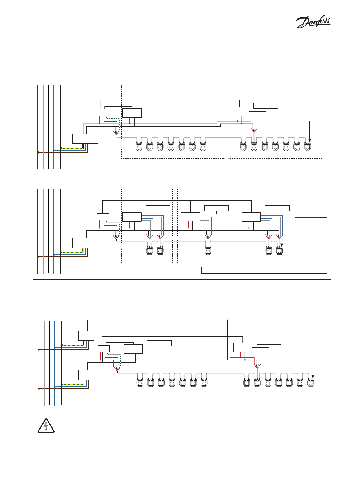
Wiring considerations
NovoCon® S
The important factors here are:
- Common ground
- 24VDC power supply is recommended
- In case more 24VAC power supplies are used
always separate the 24VAC power supplies if
different types of power supplies are used and /
or different phases are used.
Wiring with DC power supply: (recommended solution)
Digital application – 24V DC – PSU with power sharing capability, both on the same or different phases.
230/110V AC
L1 L2 L3
0
GND
24V DC
Ground
24V DC
PSU
DDC
24V DC
Ground
24V DC
PSU
Cable NovoCon® Digital
Bus
Room 1
Room
controller
Thermostat
Daisy chain cables between NovoCon® S
Room 2
Room
controller
Thermostat
X X
Cable NovoCon® Analog
Turn DIP switch
no. 8 ON for bus
termination of the
last unit on the bus.
14 | AI368140926963en-010102 © Danfoss | 2022.01
Data sheet NovoCon® S, M, L and XL Digital actuators
Wiring with DC or AC power supply:
230/110V AC
L1 L2 L3
0
230/110V AC
L1 L2 L3
0
GND
GND
24V DC / AC
Ground
24V DC / AC
PSU
24V DC / AC
Ground
24V DC / AC
PSU
Room 1 Room 2
Bus
DDC
Cable NovoCon®
Digital
Room
controller
Room 1 Room 2
Bus
DDC
Cable NovoCon® Digital
Room
controller
Digital application - One transformer
Thermostat
controller
Daisy chain cables between NovoCon® S
Analog Control Application - One transformer
Thermostat
Room
controller
X X X
Cable NovoCon® Analog
Thermostat
Cable NovoCon® Analog
Daisy chain cables between
NovoCon® S
Room
Room 3
Thermostat
XX
Cable NovoCon® Analog
Room
controller
X X
Thermostat
Turn DIP switch
no. 8 ON for bus
termination of the
last unit on the bus.
Connect Power
ground and
Analog input
ground on the
Controller.
24V power
can
also be
connected to
NovoCon® S
through the
analog cable,
but is not
required.
Turn DIP switch no. 8 ON for bus termination of the last unit on the bus.
Wiring with AC power supplies:
230/110V AC
L1 L2 L3
The power b oosters must be p rotected against over load, otherwise the power booster may be damag e if one of the othe r power boosters in the network is
disconnected.
GND
0
If the NovoCon® S network is supplied with two or more AC power boosters, c aution must be observe d when disconne cting one of the
transformers from the high voltage power line. A s the NovoCons are co nnected in a dai sy chain, there may be high voltage on the primary s ide
of the disconne cted power supp ly.
24V AC
PSU
24V AC
24V AC
PSU
24V AC
Ground
DDC
Ground
Digital application - Identical transformers, same phase
Room 1
Bus
Room
controller
Cable NovoCon®
Digital
Disconnect always both the primary and secondary side of the transformer.
Thermostat
Daisy chain cables between NovoCon® S
Room 2
Room
controller
Thermostat
Turn DIP switch
no. 8 ON for bus
termination of the
last unit on the bus.
XX
Cable NovoCon® Analog
Wires that ends in an "X" must be properly terminated.
AI368140926963en-010102 | 15© Danfoss | 2022.01
Data sheet NovoCon® S, M, L and XL Digital actuators
Wiring with AC power supply: (continued)
230/110V AC
L1 L2 L3
0
GND
24V AC
PSU
24V AC
24V AC
PSU
24V AC
Ground
Ground
Digital application - Identical or different transformers with different phases, but same ground
Room 1
Bus
DDC
Cable NovoCon®
Digital
Room
controller
Wires that ends in an "X" must be properly terminated.
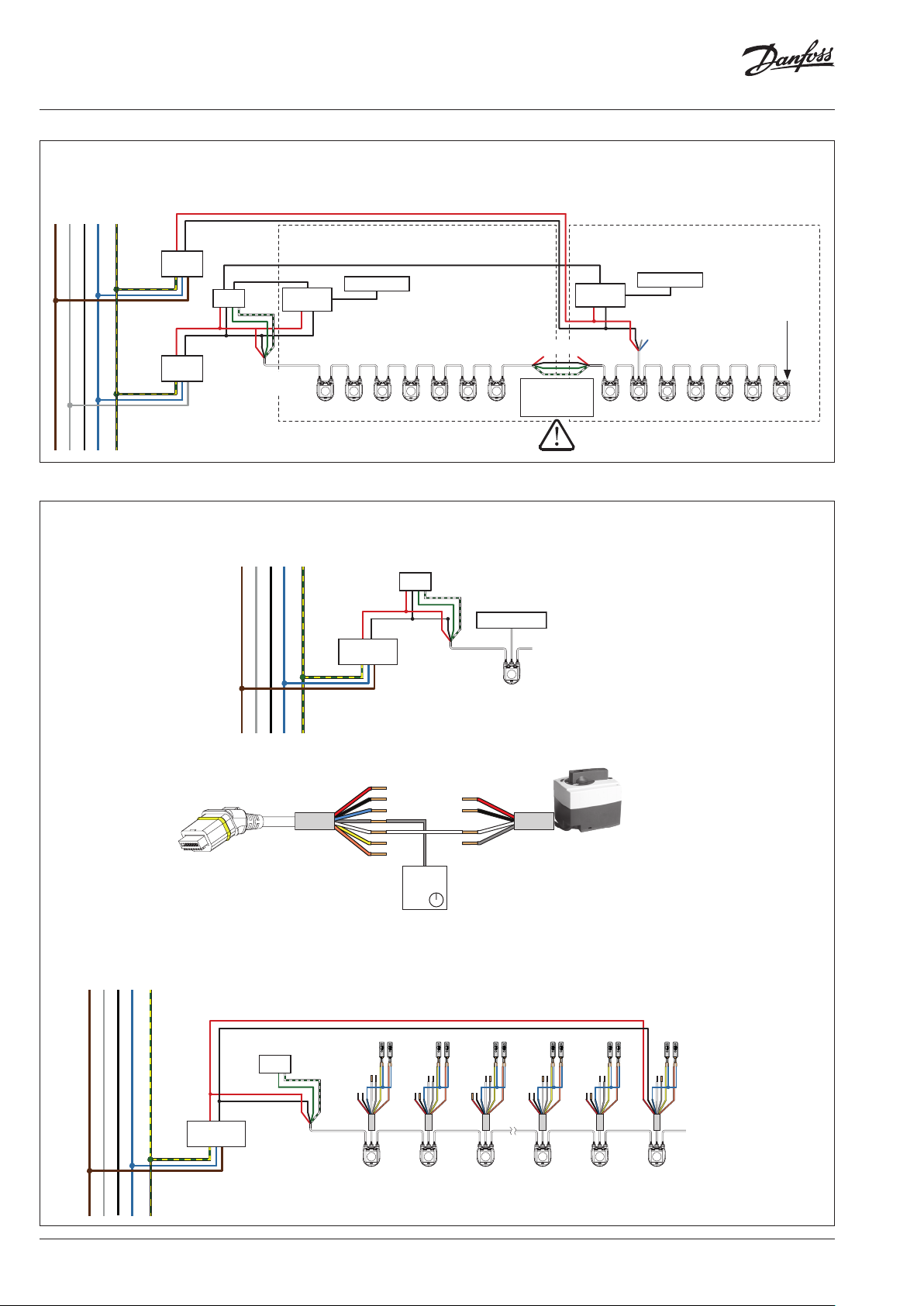
NovoCon® S ChangeOver6 application
230/110V AC
0
GND
L1 L2 L3
Thermostat
Daisy chain cables between NovoCon® S
NovoCon® S ChangeOver6 application
DDC
24V AC/DC
Ground
24V AC/DC
PSU
Cable NovoCon®
Digital
ChangeOver
Room 2
Room
controller
Cable NovoCon® Digital
X X
Disconnect
Power 24V, but
NOT ground
6
Additional products in
daisy chain if needed
Thermostat
XX
Cable NovoCon® Analog
Turn DIP switch
no. 8 ON for bus
termination of the
last unit on the bus.
Wiring Analog CO6 mode
Cable NovoCon® I/O
Wiring I/O application
230/110V AC
0
GND
24V D C/AC
L1 L2 L3
Yellow O-ring
Power
24V AC/DC
X
X
X
X
Actuator NovoCon®
ChangeOver6 Flexible
Room controller
Example using voltage booster and temperature sensors on the same NovoCon® S
24V D C/AC
Ground
PSU
DDC
Bus
Cable NovoCon®
Digital
T1 T2 T1 T2 T1 T2 T1 T2 T1 T2
XX
X
X
Cable NovoCon I/O
XX
X
X
XX
X
X
XX
X
X
T1 T2
XX
XXXX
Additional products in
daisy chain if needed
16 | AI368140926963en-010102 © Danfoss | 2022.01
Data sheet NovoCon® S, M, L and XL Digital actuators
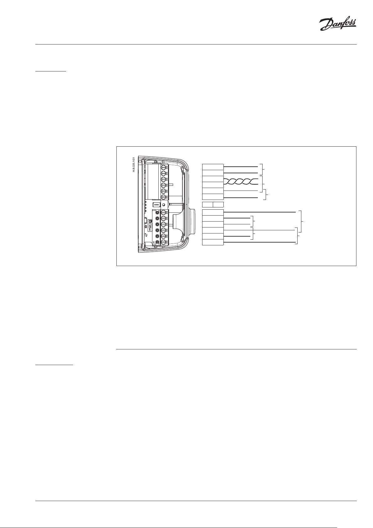
Wiring (continued)
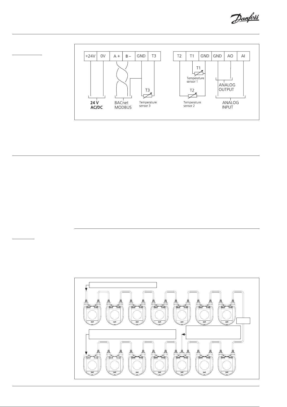
NovoCon® M
The wiring of BACnet MS/TP or Modbus RTU (RS485) must be carried out in accordance with applicable
standard ANSI/TIA/EIA-485-A-1998. Galvanic separation shall be provided for segments crossing
buildings. The bus connection ‘A+’ is the non-inverting signal and ‘B-‘ is the inverting signal wire.
Common ground shall be used for all devices on the same network including routers gateways etc.
The recommended cable type is AWG22/0.32 mm2 twisted pair. If used for longer distances, please use a
AWG20/0.5mm2 or AWG18/0.75 mm2 cable. The cable’s impedance characteristic shall be between
100-130 Ω. The capacitance between conductors shall be less than 100 pf per meter. The length of the
cables influence the communication speed. Longer cable lengths should result in lower baud rates. The
total maximum cable length allowed per network is 1200 m.
Use a minimum 20 cm separation distance between 110V/230V/400V power line cables and bus
cables. NovoCon® M has mis-wiring protection up to 30V AC/DC on all wires but be aware that if 30V
AC are connected to the Analog input, the external power supply will see this as a short circuit and
blow the fuse in the external power supply.
+24V
0V
A+
B−
GND
T3
R on R off
T2
T1
GND
GND
AO
AI
24V AC/DC
BACnet MS/TP or
Modbus RTU
Temperature
sensor 3
Temperature
sensor 1
Analog
output
Temperature
sensor 2
Analog input
NovoCon® L, XL
GND is common for a ll signals
Danfoss recommends that NovoCon® M should be used on its own sub-network for optimal
performance.
General requirements and recommendations:
• Use the termination resistor (between the 2 connectors) at the end of each daisy chain.
• Generally, one power supply is preferred.
• If two power supplies are used, they must have the same polarity and the same common ground.
• A common ground must be used for all devices on the same sub-network, including routers and
gateways.
• Galvanic separation shall be provided for segments crossing buildings.
• Total maximum sub-network cable length is 1200m.
The wiring of BACnet MS/TP or Modbus RTU (RS485) must be carried out in accordance with applicable
standard ANSI/TIA/EIA-485-A-1998. The bus connection ‘A+’ is the non-inverting signal and ‘B-‘ is the
inverting signal wire.
NovoCon® L/XL has a galvanic separated power supply, but common ground is recommended to use
for all devices on the same network including routers gateways etc.
The cable’s impedance characteristic for communication shall be between 100-130 Ω. The capacitance
between conductors shall be less than 100 pf per meter. The length of the cables influence the
communication speed. Longer cable lengths should result in lower baud rates. The total maximum
cable length allowed per network is 1200 m.
Use a minimum 20 cm separation distance between 110V/230V/400V power line cables and bus
cables. NovoCon® L/XL has mis-wiring protection up to 30V ac/dc on all wires but be aware that if 30V
ac are connected to the Analog input, the external power supply will see this as a short circuit and
blow the fuse in the external power supply.
AI368140926963en-010102 | 17© Danfoss | 2022.01
Data sheet NovoCon® S, M, L and XL Digital actuators
Wiring (continued)
NovoCon® L, XL (continued)
GND is common for a ll signals
Danfoss recommends that NovoCon® L/XL should be used on its own sub-network for optimal
performance.
General requirements and recommendations:
• Use the termination resistor (DIP switch 8) at the end of each daisy chain.
• Total maximum sub-network cable length is 1200m.
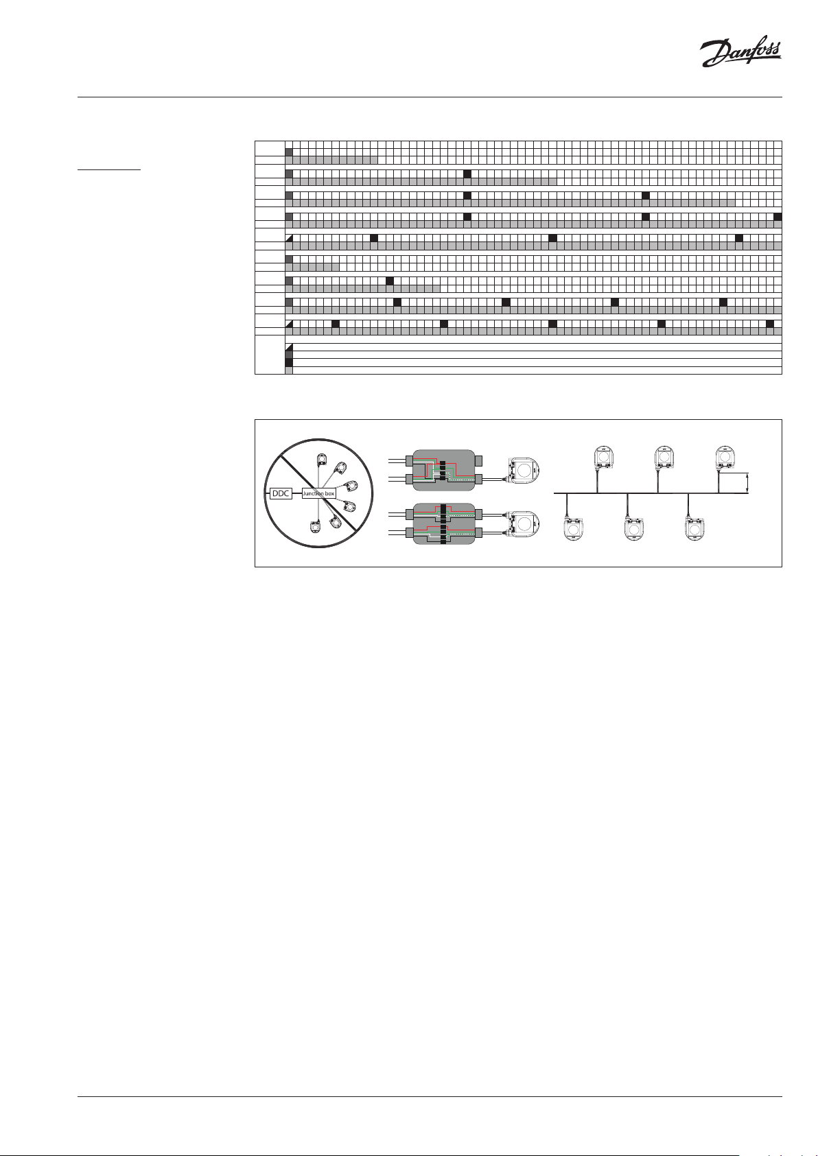
Daisy chain & Power booster
NovoCon® S
T-junctions
T-junction connections (stub lines) are not recommended.
In the event of T-Junction connections being used the following limitations must be adhered to:
- max T-junction cable length 1.5m (shortest standard digital cable)
- total length of Network max 640m (+ 100m stub length)
- max baud rate 76 kb/s 1)
- max number of devices on network 64 1)
- main cable should be standard RS485 bus, twisted pair, min thickness AWG22 / 0.32mm2.
1)
When using less than 32 devices you may attempt to raise the speed to 115 kb/s.
Star topology
Star topology is not according to the RS485 standard and should not be used with NovoCon® S, M
and L/XL.
DC Power supply (recommended)
When daisy chaining with 10m NovoCon® cables
and using a 24V DC power supply, additional
voltage boosters/power supply is needed when
12 NovoCons in series is exceeded. See table
below.
AC Power supply
When daisy chaining with 10m NovoCon® cables
and using a 24V AC power supply, additional
voltage boosters/power supply is needed when
7 NovoCons in series is exceeded. See table below.
Important: The power supply used must be able
to deliver 60% more power than the nominal
rating of NovoCon® S.
Controller and 24 Volt AC or DC Power supply
U=24V
Remember to enable DIP switch 8 for bus termination on the
last NovoCon
® S in the daisy chain
Voltage booster/power supply,
temperature sensors added directly
or through the Cable NovoCon® I/O
18 | AI368140926963en-010102 © Danfoss | 2022.01
Data sheet NovoCon® S, M, L and XL Digital actuators
T-junction
Daisy chain & Power booster
(continued)
NovoCon® S (continued)
When all devices on the sub-network are NovoCon® S, refer to the examples below for guidance.
1 2 3 4 5 6 7 8 9 10 11 12 13 14 15 16 17 18 19 20 21 22 2324 25 2627 28 2930 31 32 33 3435 36 3738 39 4041 42 43 4445 4647 48 4950 51 52 53 5455 56 5758 59 6061 62 63 64
24 Volt DC
24 Volt DC
24 Volt DC
24 Volt DC
24 Volt DC
24 Volt AC
24 Volt AC
24 Volt AC
24 Volt AC
Bus communication from the controller
Power supply w ith daisy chain fr om controller
Usage of anal og cable as volta ge booster
NovoCo n® S
If NovoCon® S is used to power external devices, a separate calculation must be made for power booster amount and
location.
max
Daisy chain
1.5m
If the supply voltage to the first device in the daisy chain is lower than 24V AC/DC, or long thin cables
other than NovoCon® cables are used, then the quantity of devices in the daisy chain may have to be
reduced.
The recommended maximum quantities of NovoCon® S are 64 pcs in one daisy chain connection.
If other BACnet devices are added with NovoCon® S in the same daisy chain connection, Danfoss
recommends a maximum of 32 pcs. to ensure sufficient network speed.
Danfoss recommends that NovoCon® S should be used on its own sub-network for optimal
performance.
General requirements and recommendations:
• Use Danfoss daisy chain cable to connect two NovoCon® S devices.
• Use Danfoss digital cable to connect NovoCon® S with another BACnet device.
• The current in cables should not exceed 3Arms at 30°C.
• Use the termination resistor (DIP switch 8) at the end of daisy chain.
• Voltage boosting may be achieved via any port.
• Generally, one power supply is preferred.
• If two power supplies are used, they must have the same polarity and the same common ground.
• A common ground must be used for all devices on the same sub-network, including routers and
gateways.
• Galvanic separation shall be provided for segments crossing buildings.
• Total maximum sub-network cable length is 1200m.
AI368140926963en-010102 | 19© Danfoss | 2022.01

Data sheet NovoCon® S, M, L and XL Digital actuators
Daisy chain & Power booster
(continued)
NovoCon® M
DC Power supply (recommended)
When daisy chaining with 10m AWG20/0,5 mm2
twisted pair cable and using a 24V DC power
supply, additional voltage boosters/power
supply is needed when 12 NovoCons in series is
exceeded.
AC Power supply
Please secure:
• Common ground
• 24VDC power supply is recommended
• In case more 24VAC power supplies are used
always separate the 24VAC power supplies if
different types of power supplies are used and /
or different phases are used.
When daisy chaining with AWG20/0,5 mm2
twisted pair cable and using a 24V AC power
supply, additional voltage boosters/power
supply is needed when 7 NovoCons in series is
exceeded.
Important: The power supply used must be able
to deliver 60% more power than the nominal
rating of NovoCon® M.
NovoCon® M in daisy chain NovoCon® M in daisy chain with NovoCon® S
NovoCon® S
+24V
0V
A+
B−
GND
T3
R on R off
T2
T1
GND
GND
AO
AI
NovoCon® S
GND is common for a ll signals
+24V
0V
A+
B−
GND
T3
R on R off
T2
T1
GND
GND
AO
AI
BACnet
MS/TP or
Modbus
RTU
If the Novo Con® M network is su pplied with t wo or more AC power bo osters, cau tion must be obs erved when
disco nnecting one o f the transfor mers from the hi gh voltage power l ine. As the Novo Cons are connec ted in a daisy
chain , there may be hig h voltage on the pr imary side of t he disconne cted power sup ply. Disconne ct always both
the prim ary and secon dary side of t he transforme r.
The powe r boosters mus t be protected ag ainst overloa d, otherwi se the power boos ter may be damag e if one of the
other po wer boosters i n the network is d isconnect ed.
BACnet MS/ TP or
+24V
0V
A+
B−
GND
T3
R on R off
T2
T1
GND
GND
AO
AI
GND is common for a ll signals
24V AC/DC
Max. 1.5 m
BACnet MS/ TP or
Modbus R TU
Modbus R TU
Modbus R TU
24V AC/DC
Junction box
BACnet MS/ TP or
24V AC/DC
20 | AI368140926963en-010102 © Danfoss | 2022.01

Data sheet NovoCon® S, M, L and XL Digital actuators
Daisy chain & Power booster
(continued)
NovoCon® L, XL
AC Power supply
Important: The power supply used must be able
to deliver 60% more power than the nominal
rating of NovoCon® L/XL.
NovoCon® L/XL in daisy chain
B−
A+
GND
GND is common for a ll signals
If the Novo Con® L/XL netw ork is supplie d with two or more AC p ower booster s, caution mus t be observed w hen
disco nnecting one o f the transfor mers from the hi gh voltage power l ine. As the Novo Cons are connec ted in a daisy
chain , there may be hig h voltage on the pr imary side of t he disconne cted power sup ply. Disconne ct always both
the prim ary and secon dary side of t he transforme r.
The powe r boosters mus t be protected ag ainst overloa d, otherwi se the power boos ter may be damag e if one of the
other po wer boosters i n the network is d isconnect ed.
BACnet
MS/TP or
Modbus RTU
Please secure:
• In case more 24V ac power supplies are used
always separate the 24V ac power supplies if
different types of power supplies are used and /
or different phases are used.
GND
A+
B−
24V AC/DC
BACnet MS/TP or
Modbus RTU
GND is common for a ll signals
Junction box
24V AC/DC
24V AC/DC
BACnet MS/TP or
Modbus RTU
Max. 1. 5m
BACnet MS/TP or
Modbus RTU
AI368140926963en-010102 | 21© Danfoss | 2022.01

Data sheet NovoCon® S, M, L and XL Digital actuators
LED Display
NovoCon® S
BACnet/Modbus (RS485) activity
BACnet/Modbus (RS485) activity
No light from LED: Actuator sees no activit y on the network.
LED turn on and off quickly, 10x/second:
Normal operation on the network communication is OK.
LED turn on and off slowly with green light, 3x /second: Normal operation on the
network - communication over longer time directly with this actuator.
BACnet/Modbus (RS485) activity with ERRORS
LED turns on and off slowly, 3x/second, with RED color: Actuator sees activit y,
but with errors.
LED turn on and off quickly, 10x/second, with RED color: Communication is OK, EXCEPT
that another device may be using the same MAC address.
Position of valve/actuator
AB-QM valve is fully closed.
AB-QM is open 1-24% of Design Flow.
AB-QM is open 25-49% of Design Flow.
AB-QM is open 50-74% of Design Flow.
AB-QM is open 75-99% of Design Flow.
AB-QM valve is open 100% of Design Flow.
Flush is active
All LEDs turns on/off with specific period.
22 | AI368140926963en-010102 © Danfoss | 2022.01

Data sheet NovoCon® S, M, L and XL Digital actuators
LED Display (continued)
NovoCon® S (continued)
Movement of valve/actuator
Information from actuator
NovoCon® S is closing the valve
All green LEDs are turned ON, then turned OFF one at the time (repeatedly).
NovoCon® S is opening the valve
All green LEDs are turned OFF, then turned ON one at the time (repeatedly).
NovoCon® S is calibrating
Green light moves forward and backwards, one by one.
De-air is active
Yellow LEDs are turned ON one by one, then turned OFF one by one (repeatedly).
Blinking function, all green LEDs turns on/off. Used to physically identif y individual
actuator on the bus.
Error during closing
Debris might be trapped under the AB-QM valve cone. Flushing may solve the problem.
Temperature inside NovoCon® S is out of the recommended range
LEDs change between showing the alarms and showing normal operation. Ambient
temperature has likely exceeded 60°C.
Internal NovoCon® S error
LEDs change between showing the alarms and showing normal bet ween operation. Try:
A: Re-calibrate.
B: Turn power off and on.
C: If the error does not disappear actuator replacement can be necessary.
Error during NovoCon® S calibration
LEDs change between showing the alarms and showing normal operation. Verify if the
NovoCon® S is correctly at tached to the valve and recalibrate.
Power supply is outside limits
LEDs change between showing the alarms and showing normal operation. Use analog
cables as voltage booster.
No Control Signal
In analog control the broken control wire is detec ted.
In CO6 mode or Inverted CO6 mode the ChangeOver6 actuator is not connected or damaged.
ChangeOver6 actuator
The ChangeOver6 actuator is in manual override or unable to reach position.
LEDs change between showing the alarms and showing normal operation.
AI368140926963en-010102 | 23© Danfoss | 2022.01

Data sheet NovoCon® S, M, L and XL Digital actuators
LED Display (continued)
NovoCon® S (continued)
NovoCon® M
Pressing the mode button during normal operation
Calibration/Reset/Flush
Press reset button. All LED's are turned off.
Keep pressing the reset button for
1 second: 1 LED ON
2 seconds: 2 LEDs ON = Start calibration (Reset).
3 seconds: 3 LEDs ON
4 seconds: 4 LEDs ON = Start flushing.
5 seconds or more = Return to normal operation.
Factory reset - reset to default settings
Press and hold the reset button and then power up the actuator, all LED's are initially
turned off.
Keep pressing the reset button until 4 LED's are turned on = Reset to default settings.
When fac tory reset is per formed it is shown by:
1 short f lash with all yellow position LED’s.
Note that af ter factory reset a calibration will be automatically be performed and all
settings are reverted to factory settings.
BACnet/Modbus (RS485) activity
BACnet/Modbus (RS485) activity
No light from LED: Actuator sees no activit y on the network.
LED turn on and off quickly, 10x/second:
Normal operation on the network communication is OK.
LED turn on and off slowly with green light, 3x /second: Normal operation on the
network - communication over longer time directly with this actuator.
Position of valve/actuator
Movement of valve/actuator
BACnet/Modbus (RS485) activity with ERRORS
LED turns on and off slowly, 3x/second, with RED color: Actuator sees activit y,
but with errors.
LED turn on and off quickly, 10x/second, with RED color: Communication is OK, EXCEPT
that another device may be using the same MAC address.
AB-QM valve is fully closed.
AB-QM is open 1-24% of Design Flow.
AB-QM is open 25-49% of Design Flow.
AB-QM is open 50-74% of Design Flow.
AB-QM is open 75-99% of Design Flow.
AB-QM valve is open 100% of Design Flow.
Flush is active
All LEDs turns on/off with specific period.
NovoCon® is closing the valve
All green LEDs are turned ON, then turned OFF one at the time (repeatedly).
NovoCon® is opening the valve
All green LEDs are turned OFF, then turned ON one at the time (repeatedly).
NovoCon® is calibrating
Green light moves forward and backwards, one by one.
De-air is active
Yellow LEDs are turned ON one by one, then turned OFF one by one (repeatedly).
24 | AI368140926963en-010102 © Danfoss | 2022.01

Data sheet NovoCon® S, M, L and XL Digital actuators
LED Display (continued)
NovoCon® M (continued)
Information from actuator
Blinking function, all green LEDs turns on/off. Used to physically identif y individual
actuator on the bus.
Error during closing
Debris might be trapp ed under the AB-QM valve cone. Flushing may solve the
Temperature inside NovoCon® is out of the recommended range
LEDs change between showing the alarms and showing normal operation. Ambient
temperature has likely exceeded 60°C.
Internal NovoCon® error
LEDs change between showing the alarms and showing normal bet ween operation. Try:
A: Re-calibrate.
B: Turn power off and on.
C: If the error does not disappear actuator replacement can be necessary.
Error during NovoCon® calibration
LEDs change between showing the alarms and showing normal operation. Verify if the
NovoCon® M is correctly at tached to the valve and recalibrate.
Power supply is outside limits
LEDs change between showing the alarms and showing normal operation.
No Control Signal
In analog control mode a broken control wire is detected.
LEDs change between showing the alarms and showing normal operation.
problem.
Pressing the mode button during normal operation
Calibration/Reset/Flush
Press reset button. All LED's are turned off.
Keep pressing the reset button for
1 second: 1 LED ON
2 seconds: 2 LEDs ON = Start calibration (Reset).
3 seconds: 3 LEDs ON
4 seconds: 4 LEDs ON = Start flushing.
5 seconds or more = Return to normal operation.
Factory reset - reset to default settings
Press and hold the reset button and then power up the actuator, all LED's are initially
turned off.
Keep pressing the reset button until 4 LED's are turned on = Reset to default settings.
When fac tory reset is per formed it is shown by:
1 short f lash with all yellow position LED’s.
Note that af ter factory reset a calibration will be automatically be performed and all
settings are reverted to factory settings.
AI368140926963en-010102 | 25© Danfoss | 2022.01

Data sheet NovoCon® S, M, L and XL Digital actuators
LED Display (continued)
NovoCon® L, XL
BACnet/Modbus (RS485) activity
BACnet/Modbus (RS485) activity
No light from LED: Actuator sees no activit y on the network.
LED turn on and off quickly, 10x/second:
Normal operation on the network communication is OK.
LED turn on and off slowly with green light, 3x /second: Normal operation on the
network - communication over longer time directly with this actuator.
BACnet/Modbus (RS485) activity with ERRORS
LED turns on and off slowly, 3x/second, with RED color: Actuator sees activit y,
but with errors.
LED turn on and off quickly, 10x/second, with RED color: Communication is OK, EXCEPT that another
device may be using the same MAC address.
Position of valve/actuator
AB-QM valve is fully closed.
AB-QM is open 1-49% of Design Flow.
AB-QM is open 50-99% of Design Flow.
AB-QM valve is open 100% of Design Flow.
Flush is active
All LEDs turns on/off with specific period.
Movement of valve/actuator
NovoCon® is closing the valve
All green LEDs are turned ON, then turned OFF one at the time (repeatedly).
NovoCon® is opening the valve
All green LEDs are turned OFF, then turned ON one at the time (repeatedly).
NovoCon® is calibrating
Green light blink alternately.
De-air is active
Yellow LEDs blink alternately.
Stand-by mode
Information from actuator
Blinking function, all green LEDs turns on/off. Used to physically identif y individual actuator on the
bus.
26 | AI368140926963en-010102 © Danfoss | 2022.01

Data sheet NovoCon® S, M, L and XL Digital actuators
LED Display (continued)
NovoCon® L, XL (co ntinued)
Information from actuator (continued)
Error during closing
Debris might be trapp ed under the AB-QM valve cone. Flushing may solve the
Error during NovoCon® calibration
LEDs change between showing the alarms and showing normal operation. Verify if the NovoCon® L/
XL is correctly attached to the valve and recalibrate.
Temperature inside NovoCon® is out of the recommended range
LEDs change between showing the alarms and showing normal operation. Ambient temperature
has likely exceeded 60°C.
Internal NovoCon® error
LEDs change between showing the alarms and showing normal bet ween operation. Try:
A: Re-calibrate.
B: Turn power off and on.
C: If the error does not disappear actuator replacement can be necessary.
Power supply is outside limits
LEDs change between showing the alarms and showing normal operation.
No Control Signal
In analog control mode a broken control wire is detected.
LEDs change between showing the alarms and showing normal operation.
Pressing the mode button during normal operation
Calibration/Reset/Flush
Press MODE button. All LED's are turned off.
Keep pressing the reset button for
1 second: 1 LED ON = Standby mode
2 seconds: 2 LEDs ON = Start calibration (Reset).
3 seconds: 1 LEDs ON
4 seconds: Start flushing. If f lushing should be stopped before the default timeout on 1 hour, press
again for 1 sec.
Factory reset - reset to default settings
Press and hold the MODE button and then power up the actuator, all LED's are initially turned off.
Keep pressing the MODE button for 4 seconds = Reset to default set tings.
When fac tory reset is per formed it is shown by:
1 short f lash with all yellow position LED’s.
Note that af ter factory reset a calibration will be automatically be performed and all settings are
reverted to factory settings.
problem.
AI368140926963en-010102 | 27© Danfoss | 2022.01

Data sheet NovoCon® S, M, L and XL Digital actuators
Door ContactDamper
Multiplex
Application principle
NovoCon® S I/O
Application principle
NovoCon® I/O and
Multiplexers/Relays
When combining the NovoCon® S and the Cable NovoCon® I/O, many options are possible
Operation example (DDC command)
NovoC on® S
Resistance input s can also be used
as galvanic insula ted digital inputs
for detecti on of window contact,
condensation s witch etc.
Connected: <90 0 Ohm.
Disconnecte d 100 kO hm.
Object /Register
AV:1 / 33280 85 DDC write s % opening value of t he AB-QM valve
AO:0 / 33286 5.5
Read on the BMS example
Object /Register
AO:0 / 33286 5.5 Voltage outpu t from NovoCon® S to remo te device
AI:0 / 33216 6.5
AI:1 / 33218 11 60 Resis tance value (Ohm) rec eived from remote d evice 1
AI:2 / 33220 12 63 Resistan ce value (Ohm) receive d from remote devi ce 2
Write value Description
DDC writ es level of voltage o n NovoCon® S analog o utput,
which is se nt to the connecte d remote device
Read value Description
Voltage le vel on the analog con trol input measur ed by
the actu ator
(may also be mA)
Multiplexers and relays (analog-digital-analog convertors) in combination with NovoCon® S, may be
used to gather information on, or control on/off devices.
Using NovoCon’s 0-10V output signal (AO:0 / 33286), multiplexer relays convert this signal in order
to switch devices on or off e.g. 7V signal from NovoCon® S is converted inside the multiplexer so
device1=on, device 2=on, device3=off. E.g. 4V signal from NovoCon® S is converted inside the
multiplexer so the device1=on, device 2=off, device3=off.
Using NovoCon’s 0-10V input signal (AI:0 / 33216) received from the multiplexers, the DDC can
decipher the meaning of the voltage signal e.g. 7V signal to NovoCon® S from the multiplexer is
deciphered by the DDC as meaning device1=on, device 2=on, device3=off. 4V signal to NovoCon® S
from the multiplexer is deciphered by the DDC as meaning device1=on, device 2=off, device3=off.
Application principle:
Central Plant Changeover –
2 pipe system
Fieldbus
Heating/
Cooling Coil
er/Multiplexer relays
Boiler
Temp.
Alarms
Fan Speed
Chiller
Digital Outputs
Fan coil unit
NovoC on® S
Actuator
Objec t /
Register
MSV:9 /
32810
MSV:3 /
32802
AV:30 /
32796
AV:31 /
32798
MSV:10 /
32 811
Window Contact
Digital Inputs
D/AA/DA/DD/A
Multiplexer/Multiplexer relays
Temp.
Condensation
Write/
read value
Selected
Val ve Typ e
Description
Digital /
The Heati ng and Cooling Des ign flow
Analog
values b elow may be used.
ISO valve se lected = l/h, ° C , kW and kg/m3.
ANSI valve s elected = GPM, ° F, kBTU a nd lb/ft
250 D esign flow set ting of Heating e. g. 250 l/h
400 Des ign flow setti ng of Cooling e.g. 4 00 l/h
When the s ystem is changed f rom central
Heating to c entral Cooling th e affected
Cooling
NovoCons m ay be written to so th e correct
Design flow will be adopted.
PIR
3
28 | AI368140926963en-010102 © Danfoss | 2022.01

Data sheet NovoCon® S, M, L and XL Digital actuators
Radiant Panels
Q
400 l/
0V 10V5V
200 l/
Application principle
ChangeOver6 - 4 pipe system
Application principle
ChangeOver6 Energy
ChangeOver
ChangeOver
Fieldbus
NovoC on® S
Separate maximum flow pre-setting for heating and for cooling
Setup
DDC
NovoCon® S
Objec t /
Register
MSV:9 /
32810
MSV:3 /
32802
AV:30 /
32796
AV:31 /
32798
Write/
read value
CO6 mode
Selected
Val ve Typ e
Description
While in CO6 m ode, the V/mA input and ou tput
signals ar e used purely for co ntrolling the
6-port valve actuator
ISO valve se lected = l/h, ° C , kW and kg/m3.
ANSI valve s elected = g/min, ° F, kBT U and lb/ft
250 D esign flow set ting of Heating e. g. 250 l/h
400 Des ign flow setti ng of Cooling e.g. 4 00 l/h
Setup
Object /Register
MSV:9 / 32810 CO6 mode
AV:32 / 33288 Power emission
AV:33 / 33290 Heating Energy Counter Accumulate Energy counter for heating
AV:34 / 33292 Cooling Energy Counter Accumulate Energy counter for cooling
MSV:3 / 32802
AI:1 / 33218 Temperature Select b etween tempe rature units or ohm s
AI:2 / 33220 Temperature Selec t between tem perature units o r ohms
AV:30 / 32796 250 Desi gn flow setti ng of Heating e.g. 250 l /h
AV:31 / 32798 400 D esign flow set ting of Cooling e.g . 400 l/h
Write/read value Description
Selec ted Valve Type
While in CO6 m ode, the V/mA input and ou tput
signals ar e used purely for co ntrolling the 6 -port
valve actuator
Calculat es energy based o n values from fl ow
feedba ck (AV:2) and temperatur e (AI:1 and AI:2)
ISO valve se lected = l/h, ° C , kW and kg/m3.
ANSI valve s elected = g/min, ° F, kBT U and lb/ft
3
3
Application principle
Analog CO6 mode
With the Object MSV:9 / register 32810 state 7 or 8 both NovoCon® S and the NovoCon® ChangeOver6 can
be controlled by a single voltage output from a room controller.
NovoCon® S can be customized to match the voltage values outputted by any room controller to both
changeover and control the flow. This is done by configuring the objects AV:50-53 / register 32848-32854.
h
NovoC on® S
h
ChangeOver
0 l/h
Setup
Object /Register
MSV:9 / 32810 Analog CO6 mode The flow and cha ngeover signal is co ntrolled by a singl e analog input.
MSV:3 / 32802 Valve type
AV:30 / 32796
AV:31 / 32798 400 D esign flow set ting of Cooling e.g . 400 l/h
BV:2 / 32786 Direct
AV:50 / 32848 0 The control sign al (V) for heati ng 100% open when MS V:9 / register 32810 = State 7 or 8.
AV:51 / 32850 3.3 Th e control signal (V ) for heating 0% o pen when MSV:9 / reg ister 32810 = State 7 or 8.
AV:52 / 32852 6 .7 The contro l signal (V) fo r cooling 0% open w hen MSV:9 / registe r 32810 = State 7 or 8 .
AV:53 / 32854 10 T he control signal ( V) for coolin g 100 % open when MSV:9 / re gister 32810= State 7 or 8.
Write/read value Description
ISO valve se lected = l/h, ° C , kW and kg/m3.
200
ANSI valve s elected = g/min, ° F, kBT U and lb/ft3
Design f low setting of H eating e.g. 200 l/h
Used to swi tch the heating and co oling control sig nal from the Room co ntroller. Must be
set befo re AV:50-53 / register 328 48-32854.
AI368140926963en-010102 | 29© Danfoss | 2022.01

Data sheet NovoCon® S, M, L and XL Digital actuators
Q
400 l/
0V 10V5V
200 l/
Q
400 l/
0V 10V5V
200 l/
Application principle
Analog CO6 mode (continued)
NovoC on® S
ChangeOver
0 l/h
Setup
Object /Register
MSV:9 / 32810 Analog CO6 mode The flow and cha ngeover signal is co ntrolled by a singl e analog input.
MSV:3 / 32802 Valve type
AV:30 / 32796
AV:31 / 32798 400 D esign flow set ting of Cooling e.g . 400 l/h
BV:2 / 32786 Inverse
AV:50 / 32848 10 The contr ol signal (V) fo r heating 100% open w hen MSV:9 / registe r 32810 = State 7 o r 8.
AV:51 / 32850 6.7 Th e control signal ( V) for heating 0% o pen when MSV:9 / reg ister 32810 = State 7 or 8.
AV:52 / 32852 3. 3 The contro l signal (V) for c ooling 0% open wh en MSV:9 / register 32810 = State 7 o r 8.
AV:53 / 32854 0 T he control signal ( V) for cooling 100 % open when MSV:9 / re gister 32810= State 7 or 8.
Write/read value Description
ISO valve se lected = l/h, ° C , kW and kg/m3.
200
ANSI valve s elected = g/min, ° F, kBT U and lb/ft3
Design f low setting of H eating e.g. 200 l/h
Used to swi tch the heating and co oling control sig nal from the Room co ntroller.
Must be se t before AV:50-53 / reg ister 32848-32854 .
h
h
NovoC on® S
ChangeOver
h
h
0 l/h
Setup
Object /Register
MSV:9 / 32810
MSV:3 / 32802 Valve type
AV:30 / 32796
AV:31 / 32798 400 D esign flow set ting of Cooling e.g . 400 l/h
BV:2 / 32786 Direct
AV:50 / 32848 0 The control sign al (V) for heati ng 100% open when MS V:9 / register 32810 = State 7 or 8.
AV:51 / 32850 3.3 Th e control signal (V ) for heating 0% o pen when MSV:9 / reg ister 32810 = State 7 or 8.
AV:52 / 32852 6 .7 The contro l signal (V) fo r cooling 0% open w hen MSV:9 / registe r 32810 = State 7 or 8 .
AV:53 / 32854 10 T he control signal ( V) for coolin g 100 % open when MSV:9 / re gister 32810= State 7 or 8.
Write/read value Description
Analog inverted
CO6 mode
200
The flo w and changeover si gnal is controlled b y a single analog inp ut.
ISO valve se lected = l/h, ° C , kW and kg/m3.
ANSI valve s elected = g/min, ° F, kBT U and lb/ft3
Design f low setting of H eating e.g. 200 l/h
Used to swi tch the heating and co oling control sig nal from the Room co ntroller.
Must be se t before AV:50-53 / reg ister 32848-32854 .
30 | AI368140926963en-010102 © Danfoss | 2022.01

Data sheet NovoCon® S, M, L and XL Digital actuators
Q
400 l/
0V 10V5V
200 l/
Application principle
Analog CO6 mode (continued)
Application principle
ChangeOver
6
NovoC on® S
ChangeOver
h
h
0 l/h
Setup
Object /Register
MSV:9 / 32810
MSV:3 / 32802 Valve type
AV:30 / 32796
AV:31 / 32798 400 D esign flow set ting of Cooling e.g . 400 l/h
BV:2 / 32786 Inverse
AV:50 / 32848 10 The contr ol signal (V) fo r heating 100% open w hen MSV:9 / registe r 32810 = State 7 o r 8.
AV:51 / 32850 6.7 Th e control signal ( V) for heating 0% o pen when MSV:9 / reg ister 32810 = State 7 or 8.
AV:52 / 32852 3. 3 The contro l signal (V) for c ooling 0% open wh en MSV:9 / register 32810 = State 7 o r 8.
AV:53 / 32854 0 T he control signal ( V) for cooling 100 % open when MSV:9 / re gister 32810= State 7 or 8.
Write/read value Description
Analog inverted
CO6 mode
200
The flo w and changeover si gnal is controlled b y a single analog inp ut.
ISO valve se lected = l/h, ° C , kW and kg/m3.
ANSI valve s elected = g/min, ° F, kBT U and lb/ft3
Design f low setting of H eating e.g. 200 l/h
Used to swi tch the heating and co oling control sig nal from the Room co ntroller. Must be
set befo re AV:50-53 / register 328 48-32854.
The ChangeOver6 is a 6-port valve with a rotary actuator that switches the flow between heating
and cooling. An AB-QM pressure independent balancing and control valve with an actuator is used
to balance the system and modulate the flow. When using the NovoCon® S for flow control, both
NovoCon® S and the Actuator NovoCon® ChangeOver6 are represented on the fieldbus network and
need no physical I/O for control.
Anti-sticking requirements:
Cooling:
To reduce the risk of the ball
valve sticking due to water
quality, the valve must be
partially rotated at least every
7 days. This is a factory default
setting and is handled by the
object MSV:11 / register 32812.
Heating:
AI368140926963en-010102 | 31© Danfoss | 2022.01

Data sheet NovoCon® S, M, L and XL Digital actuators
No mixing and shut off
Source 1 open Shut off So urce 2 open
Normally cooling is connected to port 1 and 4 and heating to port 5 and 6. If, for some reason, this
is not the case, then Inverted CO6 mode (MSV:9/32810) must be used instead.
CO6, contrary to other ball valves, includes a shut off function. This function should only be used
during maintenance and not during operation. This replaces the need for four ball valves.
The Shut off command can only be performed when the Flow Rate Setpoint (AV:1/33280) is 0.
Application mode
State 3: CO6 Mode
Normally cooling is connected
to ports 1 and 4 and heating
to ports 5 and 6.
If that is not possible, then this
may be switched and state
4: Inverted CO6 Mode must
be selected.
NovoCon® S and the ChangeOver6 actuator communicate with voltage control and feedback signal.
Whole functionality is available by using simple bus commands. For easier technical understanding,
please see below detailed explanation of the communication between NovoCon® S and the
ChangeOver6 actuator.
CO6 mode
Close
Source 1 Source 2 Angle
Cooling connected to port 1 and 4 Heating connected to port 5 and 6
Inverted CO6 mode
Heating
Close
Cooling
Source 1 Source 2 Angle
Heating connected to port 1 and 4 Cooling connected to port 5 and 6
Signal from NovoCon® S to the Actuator NovoCon® ChangeOver
Stop the motor Cooling Shut- off Heating
CO6 mode 1.0 V 2.5 V 5.5 V 8.5 V
Inverte d CO6 mode 1. 0 V 8.5 V 5. 5 V 2.5 V
6
Feedback signal from the Actuator NovoCon® ChangeOver
Unable t o move
1.0 V 2. 5 V 4.0 5.5 V
Cooling
Moving direction:
Cooling to Heating
6
Shut-off
Moving direction:
Heating to Cooling
7.0 V 8.5 V
Heating
32 | AI368140926963en-010102 © Danfoss | 2022.01

Data sheet NovoCon® S, M, L and XL Digital actuators
BACnet objects and Modbus
registers usage
- Design flow rate setting
NovoCon® S
NovoCon® M
General
There are simple BACnet and Modbus settings that are essential to the basic setup configuration of
NovoCon® in order to communicate and control. These are contained in the BACnet objects or in
decimal format Modbus registers.
Initial configuration
Application mode:
MSV:9 / 32810
Digital control (default),
Analog control,
Inverte d CO6 mode,
NovoCon® S
CO6 withou t alarms,
Inverte d CO6 without alarms ,
Analog CO6 mode,
Analog inve rted CO6 mode
CO6 mode,
Selec t Valve Type
MSV:3 / 32802
(default AB -QM 4.0
ISO DN 15)
Select application
MSV:10 / 32811
Heating (default)
Cooling
Design Flow Rate
AV:30 / 32796
Heating
AV:31 / 32798
Cooling
Activate calibration
MSV:0 / 33284 st ate 2
or use manu al
calibration
Initial configuration
Application mode:
MSV:9 / 32810
Digital control (default),
Analog control
NovoCon® M
Selec t Valve Type
MSV:3 / 32802
(default A B-QM
NovoCon® DN40)
Select application
MSV:10 / 32811
Heating (default)
Cooling
Design Flow Rate
AV:30 / 32796 Heating
AV:31 / 32798 Cooling
Activate calibration
MSV:0 / 33284 st ate 2 or
use manual calibration
NovoCon® L, XL
Initial configuration NovoCon® L
Application mode:
MSV:9 / 32810
Digital control (default),
NovoC on® L
Analog control
Selec t Valve Type
MSV:3 / 32802
(default A B-QM DN125)
Select application
MSV:10 / 32811
Heating (default)
Cooling
Desig n Flow Rate
AV:30 / 32796 Heating
AV:31 / 32798 Cooling
Initial configuration NovoCon® XL
Application mode:
MSV:9 / 32810
Digital control (default),
NovoC on® XL
Analog control
Selec t Valve Type
MSV:3 / 32802
(default A B-QM DN200)
Select application
MSV:10 / 32811
Heating (default)
Cooling
Desig n Flow Rate
AV:30 / 32796 Heating
AV:31 / 32798 Cooling
Activate calibration
MSV:0 / 33284 st ate 2
or use manu al
calibration
Activate calibration
MSV:0 / 33284 st ate 2
or use manu al
calibration
AI368140926963en-010102 | 33© Danfoss | 2022.01

Data sheet NovoCon® S, M, L and XL Digital actuators
BACnet objects and Modbus
registers usage (continued)
- Advanced configuration
and features
If the default setup of the actuator isn’t suitable, special attention has to be payed to the following objects:
MSV:9 / 32810 Application mode
MSV:3 / 32802 Selected Valve Type
MSV:10 / 32811 Application command & status
AV:30 / 32796 Design Flow Rate Heating
AV:31 / 32798 Design Flow Rate Cooling
MSV:0 / 33284 Actuator Mode and special features
AI:1 / 33218 T1 value, temperature or resistance input
AI:2 / 33220 T2 value, temperature or resistance input
AI:3 / 33222 T3 value, temperature or resistance input
AV:32 / 33288 Power emission
MSV:13 / 32815 Energy management
Application mode:
The default Application mode is Digital Control. In this mode the NovoCon® M is controlled via
fieldbus and the voltage inputs and outputs are available to connect other devices. Alternatively, in
Analog Control mode the NovoCon is expecting an analog control signal.
Selection of AB-QM valve type:
After selecting Application mode (see above), it is then necessary to select the AB-QM valve type
that the actuator is mounted on. This is done with the object MSV:3 / 32802 Selected Valve Type.
The present value of MSV:3 / 32802 may be set to values between 1 and 9. Each number represents a
specific AB-QM valve type, which can be found in the table: Valve type selection. The default value for
MSV:3 / 32802 is 1 i.e. AB-QM ISO DN40 valve.
Selection and setting of engineering units:
If there is a need to change the default engineering units, this is done in BACnet via the object’s
engineering units property or in separate objects, and in Modbus via separate registers. See the
BACnet and Modbus tables for more details.
Setting the Design Flow Rate:
The designed maximum flow rate of the controlled system should be set if the nominal flow of
the valve does not correspond to the designed maximum flow rate. The Design Flow Rate is set by
changing the present value of:
• AV:30 / 32796 Design Flow Rate for Heating applications
• AV:31 / 32798 Design Flow Rate for Cooling applications
Temperature measurements:
AI:1 / 33218 Temperature T1 or resistance input, AI:2 / 33220 Temperature T2 or resistance input
and AI:3 / 33222 Temperature T3 or resistance input are used to measure the temperature with
temperature sensors. The resistance value may also be shown directly if selected, allowing these
inputs to be used for other purposes than measuring temperature e.g. window contacts or other
potential free contacts. Closed circuit <900Ω, open circuit 100kΩ.
Power emission:
AV:32 / 33288 Power emission is used to show the present hydronic power emission of the terminal unit,
based on calculations from water flow rate and the temperature difference between supply and return pipes.
Energy Counter:
Either the Cooling or Heating thermal energy used is counted and logged under AV:33 / 33290 or
AV:34 / 33292. This function is enabled and disabled with MSV:12 / 32814.
Flushing a system:
Actuator Mode and Special Features MSV:0 / 33284 has an option which allows the user to flush the system
via the fieldbus. To start flushing the system, set MSV:0 / 33284 to 3, Flush. The actuator will then open up
the AB-QM valve completely. Flush will end when:
• MSV:0 / 33284 is set back to 1 = Normal operation
• Or the power is cycled.
• Or the flush function times-out after 1 hour.
When flushing ends, the actuator returns to normal operation.
De-Airing of a system:
With MSV:0 / 33284, is it also possible to start the De-Air function in the actuator. This function will
open and close the AB-QM valve a number times, helping getting rid of trapped air in the hydronic
system. Start De-Air by setting MSV:0 / 33284 to 4. De-air will run undisturbed until it ends. The state
of the actuator will then go back to normal operation i.e. MSV:0 / 33284 = 1, Normal.
Controlling the actuator:
Under normal operation (Digital Control) of the actuator, where the flow through the AB-QM valve is
to be controlled, the object Flow Rate Setpoint AV:1 / 33280 is used. The default setting for the Flow
Rate Setpoint engineering unit is %.
This is the most suitable setting as the controller does not need to know anything about the Design
Flow Rate setting of the actuator. The output signal from the controller needs only to be set up so it
regulates from 0 to 100% of the Heating Design Flow Rate AV:30 / 32796 or Cooling Design Flow Rate
AV:31 /32798. Alternative Design Flow Rate AV:0 / 32768 can be used.
To change the flow rate through the valve, the present value of AV:1 / 33280 is written-to, in the range
0 – 100%.
If the engineering unit selected for AV:1 / 33280 must be l/h, the Flow Rate Setpoint through the valve
must be written-to in integers representing l/h. An example of this could be a controller writing values
to the actuator in the range 0 to 7500 l/h for a DN40 valve.
Alarms and warnings:
System issues can be detected by using BACnet object values BV:10 to BV:24 or Modbus register 33536, see
BACnet and Modbus tables for more details.
34 | AI368140926963en-010102 © Danfoss | 2022.01

Data sheet NovoCon® S, M, L and XL Digital actuators
kW
Time
l/
d
Optimize BACnet network
speed
Energy management
MSV:13 / 32815
Reducing Unnecessary PollforMaster Traffic
The MAX_MASTER setting in NovoCon® S can be set above the number of the highest used MAC
address in the MS/TP sub network. The MAX_MASTER property is found in the Device object and has
a default value of 127. If used, it should be noted that the MAX_MASTER property value should be
adjusted accordingly at a later stage prior to adding more devices to the network when the highest
MAC address exceeds the MAX_MASTER property value.
Important: Before MAX_MASTER can be set, ensure ALL network device MAC addresses are below
the intended MAX_MASTER property value. Failure to do this may result in network communication
problems.
Allocating Correct INFO_FRAMES
Setting for Controller:
Network Routers and Controller devices that transport traffic in the MS/TP network require a higher
number of INFO_FRAMES than NovoCon® S. Therefore, these devices should have a higher value than
NovoCon® S. A general rule of thumb for the sub network router’s MAX_INFO_FRAMES property
value is equal to the amount of MS/TP devices in the router’s sub network. The MAX_INFO_FRAMES
property is found in the Device object of MS/TP devices. NovoCon’s default MAX_INFO_FRAMES
value is 1.
General Information - Energy Limitation States:
For all ‘limitation’ states within MSV:13/32815, a warning will be activated and made visible on the
bus to inform the user that NovoCon® has taken control of the flow rate through the AB-QM valve.
Whilst under NovoCon® control, the valve will not be closed at any time i.e. closing % constraints are
contained within its algorithms, although an external device’s control signal will always be able to
close the valve. If the energy limitation settings are unobtainable without NovoCon® closing itself, a
warning will be activated to inform the user that the set-point value is ‘out of range’. Please note that
NovoCon® will not automatically relinquish control of the flow rate as soon as the set-point is achieved
if the external device e.g. DDC differs greatly with that of NovoCon’s® calculated flow rate/opening %.
TIP: This information may be used by the user to improve the external control device’s PID.
General Information - Energy Control States:
For all ‘control’ states, except Power control, within MSV:13/32815, NovoCon® takes full control over the flow
rate through the AB-QM valve and will not accept a control signal from an external device. Whilst under
NovoCon® control, the valve will not be fully closed at any time i.e. closing % constraints are contained
within its algorithms. If the energy control settings are unobtainable without NovoCon® closing or opening
itself fully, a warning will be activated to inform the user that the set-point value is ‘out of range’.
If MSV:13 (energy application) is switched from "not used" to:
- power limitation/control or delta temp. lim./control: T1 function and T2 function are locked to Supply/
return temperature – these cannot be changed until app is disabled.
- return temp. limitation/control: The terminal corresponding to "return temperature function" is locked
and cannot be changed until energy app is disabled.
Power Manager
State 1: Not active
Energy management applications are disabled.
State 2: Power limitation (chilled water example)
NovoCon® S calculates the instantaneous hydronic power used and will then, when required, override
the DDC control signal and limit the flow rate / hydronic power according to the user defined values
in object / register AV:35 or 36 / 32832 or 32834. The hydronic power is limited by closing the valve
until the kW value measured, once again, falls below the defined limit. There are user defined limits
for both Cooling Power and Heating Power. When this limitation is active, the warning object BV:23 /
bit 23 in register 33536 will be set to ‘on’.
Application example: When the “Power” is limited in this way we are able to prevent over
consumption (during peak load) and balance design power distribution.
Object/
Register
Energy saving
h
DDC
Control
NovoCon
Control
40kW limit seng
Time
NovoCon override perio
DDC
Control
MSV:9 /
32810
MSV:3 /
32802
AV:31 /
32798
MS V:13 /
328 15
AV:36 /
32834
AV:4 6 /
32862
Write/read
Selected
Val ve Typ e
Cooling Desig n flow setting o f Cooling e.g. 40 0 l/h
Limitation
Cooling m ax.
power value
Description
value
NovoCon /AB- QM opening de gree
Digital
command v ia BUS
ISO valve se lected = l/h, ° C , kW and kg/m3.
ANSI valve s elected = g/min, ° F and kBTU.
Power
The Cooli ng max hydronic pow er value
that NovoC on will not exceed e. g. 2kW
The valu e that NovoCon will en sure the
calcula ted power emissio n will
not excee d e.g. 4kW
Energy management minimum flow in
10%
percent age of Design fl ow Rate.
State 3: Power control
Power emission is controlled directly in kW, kBTU or % and not l/hr / GPM. The flowrate through the
valve is controlled by the Flow Rate setpoint AV:1 in kW or kBTU/h (selected in MSV:21 / 32788) and is
based on the flowrate and temperature inputs which are used to calculate the power consumption.
Application example: Tempering a space (e.g. in storage hall) where we can set and keep the energy
output constant.
AI368140926963en-010102 | 35© Danfoss | 2022.01

Data sheet NovoCon® S, M, L and XL Digital actuators
°C
Nov
n
c
o
ntrol
Nov
o
C
n
t
rol
N
andma
i
t
a
i
onsta
n
t
∆
T
°C
return
suppl
Time
Energy management
MSV:13 / 32815 (continued)
Delta T Manager
State 4: Min. Delta T limitation (heating water example)
NovoCon® S, when required, overrides the DDC control signal and maintains a minimum temperature
difference between the flow and return temperatures by starting to close the valve when the user
defined minimum delta T is not achieved. As the flow temperature increases/decreases, so will the
calculated minimum set-point for the return temperature. This always ensures a minimum energy
transfer to the FCU irrespective of the flow temperature. This state may also be used in CO6 mode and
will apply the appropriate value whilst in cooling/heating mode.
For heating, the delta T value is set in object / register AV:37 / 32836. When conditions allow for this
limitation to be activated, the warning object BV:23 / bit 23 in register 33536 will be set to ‘on’.
Application example: When we would like to improve the efficiency of boiler/chiller we can define the
Minimum Delta T in the system with respect to outside temperatures.
HW Flow
Min. ∆T Seng
HW Return
l/h
Min ∆T band seng
Energy saving Energy saving
DDC
NovoCon
control
oCo
control
DDC
control
Time
Time
NovoCon
con
control
Object/
Register
MSV:9 /
32810
MSV:3 /
32802
MSV:10 /
32 811
AV:30 /
32796
MSV:13 /
328 15
o
DDC
control
AV:37 /
32836
AV:46 /
32862
Write/
read value
Selected
Val ve Typ e
Heating
Description
NovoCon /AB- QM opening de gree
Digital
command v ia BUS
ISO valve se lected = l/h, ° C and kW.
ANSI valve s elected = GPM, ° F and kBTU.
Any control a lgorithms used a re with
AI:1>AI:2 in mind
250 Design f low setting of H eating e.g. 250 l/h
Min. Del ta T
limitation
Heating D elta
T value
Constant ly ensures the fl ow and return
temperature difference do not fall below
a specif ied value
The delt a T value that NovoCo n will not
fall bel ow e.g. 20°C
Energy management minimum flow in
10%
percent age of Design fl ow Rate.
State 4: Min. Delta T limitation (chilled water example)
Application example: When we would like to improve the efficiency in the system we can define the
Minimum Delta T in the system.
Object/
Register
MSV:9 /
32810
Min ∆T
seng
y
l/h
DDC
control
Energy saving Energy saving
NovoCon
Min ∆T limitaon acvated
DDC
control
Time
NovoCon
Min ∆T lim. ac.
MSV:3 /
32802
MSV:10 /
32 811
AV:31 /
32798
MSV:13 /
328 15
AV:38 /
32838
AV:46 /
32862
Write/read
Digital
Selected
Val ve Typ e
Cooling
Description
value
NovoCon /AB- QM opening de gree
command v ia BUS
ISO valve se lected = l/h, ° C , kW and kg/
m3.
ANSI valve s elected = g/min, ° F, kBT U
and lb/f t3
Any control a lgorithms used a re with
AI:1>AI:2 in mind
400 Design fl ow setting of Coo ling e.g. 400 l/h
Min. del ta T
limitation
Cooling D elta
T value
Constant ly ensures the fl ow and return
temperature difference do not fall below
a specif ied value
The delt a T value that NovoCo n will no
fall bel ow e.g. 5°C
Energy management minimum flow in
10%
percent age of Design fl ow Rate.
State 5: Set Delta T control (heating water example)
NovoCon® S constantly overrides the DDC control signal when activated and maintains a constant
temperature difference between the flow and return temperatures by opening and closing the valve.
When the flow temperature increases/decreases, so will the calculated delta T set-point for the return
temperature. This always ensures a constant delta T across the FCU irrespective of the flow temperature.
This state may also be used in CO6 mode and will apply the appropriate value whilst in cooling/heating
mode.
The constant delta T for heating is set in object / register AV:37 / 32836 and for cooling AV:38 / 32838.
Application example: Tempering a space (e.g. in storage hall) where we can set and keep a constant Delta T.
Object/
°C
HW Flow
Set∆Tseng
HW Return
Time
l/h
ovoCon is acng as DDC controller
NovoCon is acng as DDC controller
andmaintains constant ∆T
n
nsc
Time
Register
MSV:9 /
32810
MSV:3 /
32802
MSV:10 /
32 811
AV:30 /
32796
MSV:13 /
328 15
AV:37 /
32836
AV:46 /
32862
Write/read
Digital
Selected
Val ve Typ e
Heating
Description
value
NovoCon /AB- QM opening de gree
command v ia BUS
ISO valve se lected = l/h, ° C and kW.
ANSI valve s elected = GPM, ° F and kBTU.
Any control a lgorithms used a re with
AI:1>AI:2 in mind
250 Design f low setting of H eating e.g. 250 l/h
Set Delt a T
control
Heating D elta
T value
Constant ly ensures the fl ow and return
temperature difference do not deviate
from a spe cified value
The delt a T value that NovoCo n will use as
setpoi nt e.g. 20°C
Energy management minimum flow in
10%
percent age of Design fl ow Rate.
When this limitation is active, the warning object BV:23 / bit 23 in register 33536 will be set to ‘on’.
36 | AI368140926963en-010102 © Danfoss | 2022.01

Data sheet NovoCon® S, M, L and XL Digital actuators
°C
Time
°C
l/
Nov
oCondoe
s
n
t
acc
e
p
t
D
D
C
flow
c
o
ntrolan
d
mai
t
a
i
s
c
n
sta
ntR
etu
rnT
Energy management
MSV:13 / 32815 (continued)
State 6: Return T limitation (chilled water example)
NovoCon® S ensures the min. return temp. which is set in register / object AV:40 / 32842.
This function will mainly be used for a Cooling application where the return temperature is higher than
the flow temperature. NovoCon® S overrides the DDC control signal when activated and maintains a
minimum return temperature by starting to close the valve when the user defined minimum return
temperature is not achieved. When conditions allow for this limitation to be active, the warning object
BV:23 / bit 23 in register 33536 will be set to ‘on’.
Application example:
To improve chiller efficiency and ensure proper flow temperature for cooling systems, we can prescribe
minimum return temperature to avoid COP reduction as well as low Delta T syndrome.
Object/
Register
CW Return
CW Flow
l/h
DDC
control
NovoCon
control
Time
Time
Min. Return °C
DDC
control
MSV:9 /
32810
MSV:3 /
32802
MSV:10 /
32 811
AV:31 /
32798
MSV:13 /
328 15
AV:40 /
32842
AV:46 /
32862
Write/read
Selected
Val ve Typ e
Cooling
Description
value
NovoCon /AB- QM opening de gree
Digital
command v ia BUS
ISO valve se lected = l/h, ° C and kW.
ANSI valve s elected = GPM, ° F and kBTU.
Any control a lgorithms used a re with
AI:1<AI:2 in mind
400 Design fl ow setting of Coo ling e.g. 400 l/h
Min. Return T
limitation
Cooling T 2
Ensures the r eturn temperat ure does not
fall bel ow a specified v alue
The valu e that NovoCon will en sure T2
value
will not fa ll below e.g. 13°C
Energy management minimum flow in
10%
percent age of Design fl ow Rate.
State 6: Return T limitation (heating water example)
NovoCon® S ensures the max return temp. set in register / object AV:39 / 32840.
This function will mainly be used for a Heating application where the return temperature is lower than
the flow temperature. NovoCon® S overrides the DDC control signal when activated and maintains a
maximum return temperature by starting to close the valve when the user defined maximum return
temperature is not achieved. When conditions allow for this limitation to be active, the warning object
BV:23 / bit 23 in register 33536 will be set to ‘on’ .
Application example: Heating systems that require a maximum return temperature for efficient heat
source generation e.g. condensing boilers and heat pumps.
Object/
h
HW Flow
HW Return
DDC
control
Energy saving
NovoCon
control
DDC
control
Energy saving
Max. Return
Time
NovoCon
control
Register
MSV:9 /
32810
MSV:3 /
32802
MSV:10 /
32 811
AV:30 /
32796
MSV:13 /
328 15
AV:39 /
32840
AV:46 /
32862
Write/read
Selected
Val ve Typ e
Heating
Max. Return T
limitation
Heating T 2
Description
value
NovoCon /AB- QM opening de gree
Digital
command v ia BUS
ISO valve se lected = l/h, ° C and kW.
ANSI valve s elected = GPM, ° F and kBTU.
Any control a lgorithms used a re with
AI:1>AI:2 in mind
250 Design f low setting of H eating e.g. 250 l/h
Ensures the r eturn temperat ure does not
rise above a s pecified va lue
The valu e that NovoCon will en sure T2
value
will not ri se above e.g. 60°C
Energy management minimum flow in
10%
percent age of Design fl ow Rate.
State 7: Set Return T control (heating water example)
A constant return temperature T2 value is set in object / register AV:39 / 32840 (Heating) or AV:40 /
32842 (Cooling). NovoCon® S constantly overrides the DDC control signal and maintains a constant
return temperature by opening and starting to close the valve when the user defined Return T is
exceeded or not achieved. When the flow temperature increases/decreases, the Return T set-point
remains the same. This will ensure a constant return temperature back to the energy source.
Application example: When we intend to use the return water for secondary usage e.g. pre-heat on a AHU
or a standalone terminal unit in which the T2 value is used as the temperature set-point to be maintained.
°C
HW Flow
HW Return
Object/
Register
MSV:10 /
Time
l/h
NovoCon doesnt accept DDC flow control and
n
n
o
maintains constant Return T
Time
MSV:13 /
MSV:9 /
32810
MSV:3 /
32802
32 811
AV:30 /
32796
328 15
AV:39 /
32840
AV:46 /
32862
Write/read
Selected
Val ve Typ e
Heating
Description
value
NovoCon /AB- QM opening de gree
Digital
command v ia BUS
ISO valve se lected = l/h, ° C and kW.
ANSI valve s elected = GPM, ° F and kBTU.
Any control a lgorithms used a re with
AI:1>AI:2 in mind
250 Design f low setting of H eating e.g. 250 l/h
Set Return T
control
Heating T 2
Constant ly ensures the retu rn temperature
does not d eviate from a speci fied value
The retur n T value that NovoCo n will use
value
as setpo int e.g. 40°C
Energy management minimum flow in
10%
percent age of Design fl ow Rate.
AI368140926963en-010102 | 37© Danfoss | 2022.01

Data sheet NovoCon® S, M, L and XL Digital actuators
Commissioning/connection
of flow sensor to:
NovoCon® S
NovoCon® S supports connection of flow sensor directly to NovoCon® IO cable. Flow sensor must be
connected to AI and AO terminal. NovoCon must be set to digital mode (MSV:9/32810 = 2), output
functionality set to Inactive (BV:3/32817 = 0) and value of output (AO:0/33286 = 10) on 10 V. You also
need to select AI (MSV: 41/32821) input for connecting flow sensor.
To get right flow sensor value it is very important to set right value of liters per pulse on NovoCon®
(AV: 43/32864). Usually this is written on flow sensor specification sheet. If we would like to use flow
sensor for calculating energy we must also set register MSV12/32814*.
AI
Cable NovoCon® I/O
Yellow O-ring
Red Power 24V (in/out)
SonoSensor 30
19
18
Terminal Nr. Description
18 Volume pulse output (+)
19 Ground (-)
Black Power ground (in/out)
Blue Ground T1, T2 V/mA input & V output signal
Grey V/mA input signal
White V output signal
Yellow T1 or resistance input
Orange T2 or resistance input
Object/Register Write/read value Description
MSV:9 / 32810 2: Digital mode Application mode
BV:3 / 32817 0: Inactive Output feedback
AO:0 / 33286 10 Value on out put
MSV:41 / 32821 3: Flow sensor AI input
AV:43 / 32864 0.04 (depends on flow sensor) Pulse volume (liter/pulse)
MSV:12 / 32814 3: ON , flow sensor on re turn pipe Energy counting method*
*Energy counting method
MSV: 12 / 32814
State 1: Off
NovoCon® S is not calculating energy.
State 2: On, indicated flow
NovoCon® S is calculating energy based on temperature difference between T1 and T2 and using
indicated flow.
State 3: On, flow sensor on return pipe
NovoCon® S is calculating energy based on temperature difference between T1 and T2 and using flow
from flow sensor installed on return pipe.
State 4: On, flow sensor on supply pipe
NovoCon® S is calculating energy based on temperature difference between T1 and T2 and using flow
from flow sensor installed on supply pipe.
38 | AI368140926963en-010102 © Danfoss | 2022.01

Data sheet NovoCon® S, M, L and XL Digital actuators
Commissioning/connection
of flow sensor to: (continued)
NovoCon® M
NovoCon® M supports connection of flow sensor directly to NovoCon® inputs. Flow sensor must be
connected to T3 and GND terminal. NovoCon must be set to digital mode (MSV:9/32810 = 2). You also
need to select T3 (MSV: 44/32821) input for connecting flow sensor.
To get right flow sensor value it is very important to set right value of liters per pulse on NovoCon®
(AV: 43/32864). Usually this is written on flow sensor specification sheet. If we would like to use flow
sensor for calculating energy we must also set register MSV12/32814*.
T3
NovoCon M
+24V
0V
A+
B−
GND
T3
R on R off
T2
T1
GND
GND
AO
AI
SonoSensor 30
19
18
Terminal Nr. Description
18 Volume pulse output (+)
19 Ground (-)
Object/Register Write/read value Description
MSV:41 / 32824 3: Flow sensor T3 inp ut
AV:43 / 32864 0.04 (depends on flow sensor) Pulse volume (liter/pulse)
MSV:12 / 32814 3: ON , flow sensor on re turn pipe Energy counting method*
*Energy counting method
MSV: 12 / 32814
State 1: Off
NovoCon® M is not calculating energy.
State 2: On, indicated flow
NovoCon® M is calculating energy based on temperature difference between T1 and T2 and using
indicated flow.
State 3: On, flow sensor on return pipe
NovoCon® M is calculating energy based on temperature difference between T1 and T2 and using
flow from flow sensor installed on return pipe.
State 4: On, flow sensor on supply pipe
NovoCon® M is calculating energy based on temperature difference between T1 and T2 and using
flow from flow sensor installed on supply pipe.
AI368140926963en-010102 | 39© Danfoss | 2022.01

Data sheet NovoCon® S, M, L and XL Digital actuators
Commissioning/connection
of flow sensor to: (continued)
NovoCon® L, XL
NovoCon® L/XL supports connection of flow sensor directly to NovoCon® inputs. Flow sensor must be
connected to T3 and GND terminal. NovoCon must be set to digital mode (MSV:9/32810 = 2). You also
need to select T3 (MSV: 44/32821) input for connecting flow sensor.
To get right flow sensor value it is verry important to set right value of liters per pulse on NovoCon®
(AV: 43/32864). Usually this is written on flow sensor specification sheet. If we would like to use flow
sensor for calculating energy we must also change register MSV12/32814*.
T3
GND is common for all signals
Object/Register Write/read value Description
MSV:41 / 32824 3: Flow sensor T3 inp ut
AV:43 / 32864 0,04 (depends on flow sensor) Pulse volume (liter/pulse)
MSV:12 / 32814 3: ON , flow sensor on re turn pipe Energy counting method*
NovoCon L/XL
SONO 3500 CT
56
57
Terminal Nr. Description
56 Volume pulse output (+)
57 Ground (-)
*Energy counting method
MSV: 12 / 32814
State 1: Off
NovoCon® L/XL is not calculating energy.
State 2: On, indicated flow
NovoCon® L/XL is calculating energy based on temperature difference between T1 and T2 and using
indicated flow.
State 3: On, flow sensor on return pipe
NovoCon® L/XL is calculating energy based on temperature difference between T1 and T2 and using
flow from flow sensor installed on return pipe.
State 4: On, flow sensor on supply pipe
NovoCon® L/XL is calculating energy based on temperature difference between T1 and T2 and using
flow from flow sensor installed on supply pipe.
Settings connected to flow sensor (NovoCon S/M/L/XL):
If either T1 or T2 ohmic input terminal is used for flow sensor or disabled:
energy app can't be switched to power lim./control or delta temp. lim./control, but might be switched
to return temp. lim./control.
The former depends whether if the return temperature function is selected on the other terminal,
which is not used for flow sensor connection.
If analog input terminal function is used for flow sensor or disabled, the following application
modes in MSV:9 are not available:
1: Analog control - AI used for control signal
3: CO6 mode - AI used for CO6 status
4: Inverted CO6 mode - AI used for CO6 status
7: Analog CO6 mode - AI used for control signal
8: Inverted analog CO6 mode - AI used for control signal
In other words, the MSV:9 can't be switched to "Analog control" or to the CO6 modes except mode
5&6 (CO6 without alarms).
If MSV:9 application mode is used in "Analog control" or in combination with CO6 except states
5 and 6 (CO6 without alarms):
The AI terminal function is locked to state 2 "Analog input (voltage or current)" and can't be changed.
40 | AI368140926963en-010102 © Danfoss | 2022.01

Data sheet NovoCon® S, M, L and XL Digital actuators
Auto baud rate
NovoCon® should be connected
after, or at the same time as,
other devices. NovoCon® will
then adapt to it's network's
baud rate automatically.
Baud rate MSV:6 / 32804 must be set to 1 (default).
If the NovoCon® observes activity on the bus within 45 seconds after powering up, then it adopts the baud
rate presently used on the network by other BACnet devices. If the actuator does not see activity on the
network within this time, it generates a token and sends the token out at the default baud rate of 38400bps.
Auto Baud rate
Yes
Receiving data correct -
no framing errors?
No
Change baudrate
Activit y on the
bus?
Yes
Has a random time of 45
No
to 60 seconds elapsed?
Generate Token @
Use current
baudrate
No
Yes
38400bps
End Auto Baud rate
Auto MAC Addressing
- BACnet only
MAC address assignment method MSV:5 must be set to 1 (default).
The NovoCon® actuator observes for occupied MAC addresses on the sub-network and then
automatically assigns an available MAC address to the actuator only on first Power up. Assuming the
address has not already been manually selected by DIP Switches. If a MAC address collision arises an
Auto MAC addressing is enabled. This function will start the search for an available MAC address again.
When an available MAC address is found, an “I-Am” notification will be sent out via BACnet.
Please note that consecutive MAC addresses may not always be assigned.
Auto MAC addressing
Obser ve Poll for Master an d
Reply to Po ll For Master
Found another master
on the network
Yes
Listen to Poll For Master a nd
Reply for Poll For Master.
Generate table with possible
free MAC addresses
Listened for Poll for M aster
in a complete cycle?
Yes
Select randomly one of free
MAC address es and send out an
lam with selected MAC address.
No
No
Set MAC address = 1
Start generate
Token
Collision
MAC address
Collision o n MAC
address detected?
Yes
Auto MAC address
enabled?
Yes
Start Auto
MAC address
function
End Collisio n MAC
address
No
No
End of Auto MAC addressing .
AI368140926963en-010102 | 41© Danfoss | 2022.01

Data sheet NovoCon® S, M, L and XL Digital actuators
BACnet Objects - Analog Value
Ident
AV:0 Design Flow Rate
AV:1 Flow Rate Setpoint
AV:2 Flow Rate feedback %, L/h, GPM R 0
AV:3 Control Fal lback Time 72: Minutes R/W 0
AV:4 Alpha Value 95: No unit s R/W 0.05 1.0 1.0 0.01
AV:5
AV:6
AV:7 MAC Address 95: No u nits R/W 1 12 6 na 1 MAC Address u sed for BACnet commun ication. Yes
AV:8 Temper ature in the Actua tor °C, °F R -20 10 0 °C 0.5
AV:9 Total Operating Hours Hours R 0 MAX na 1 Total Operati ng Hours of the ac tuator. Yes
AV:10 Minutes since la st power-up Minutes R 0 MAX na 1 Minutes s ince the last power- up of the actuator. No
AV: 11 Minutes since last calibration Minutes R 0 MAX na 1 Minutes si nce the last time the a ctuator was cali brated to an AB- QM valve. Yes
AV:12 Minutes since fully closed Minutes R 0 MA X na 1 Minutes si nce the last time the AB -QM valve was f ully closed. Yes
AV:13 M inutes Since fully O pened M inutes R 0 MAX na 1 Minutes sin ce the last time the AB -QM valve was fu lly opened. Yes
AV:14 Lifetime estimate na R 0 MAX na 0.01
AV:15 Server Message Count na R 0 MAX na 1 Server Message Count No
AV:16 Server Message Received na R 0 MAX na 1 Server Message Received No
AV:17 Server Error Count na R 0 MAX na 1 Ser ver Error Count No
AV:18 Server Message sent na R 0 MAX na 1 Ser ver Message sent No
AV:19 Server Timeout Error na R 0 MAX na 1 Server Timeout Error No
AV:20
AV:21
AV:22
AV:23
AV:24
AV:25
AV:26
AV:27 Alarm summary count No units R na na 0 na
AV:30 Heating Design Flow Rate
AV:31 Cooling Design Flow Rate
AV:32 Power emission
Object /
Parameter name
Valve closing o r opening
time
Voltage of int ernal power
supply
Serial Num ber of the
actuator
The name of th e Selected
valve is show n here
Valve positi on at nominal
flow
Maximum v alue for the
Design Flow R ate
The name of th e User
Defi ned Valve is shown her e
Valve positi on at nominal
flow for Us er Defined Valve
Maximum v alue for the
Design Flow i n the User
Defin ed Valve
Unit
98: %
136: L/h
89: GPM
98: %
136: L/h
89: GPM
48: kW
157: kBTU/h
73: Seconds R/W 18 70 0 na 1
Volts R 12 50 na 0 .01
L/h or GPM , Unit type
comes from M SV:3
Select ed Valve Type
Millimetre R na na na 1 Position i n mm for nominal fl ow of the selecte d AB-QM valve. na
136: L/h or 89: GPM .
Unit typ e written here
is copied to th e Valve
Table. Default: L/h
30: Millimetre R/W 1. 5 5.8 4 0.01
98: % R/W 10 0 150 100 1
98: %
136: L/h
89: GPM
98: %
136: L/h
89: GPM
48: kW
157: kBTU/h
Read/
Write
R/W
R/W 0
na R na na na 1
R na na na 1 Nomi nal flow of the sel ected AB-Q M valve is shown in the p resent value. na
%
R na
R/W 1
R/W
R/W
R 0 na na 0 .01
Min Max
AB-QM 4. 0 DN15-DN32:
10% of nominal f low
AB-QM D N10-DN32: 20%
of nominal f low
AB-QM D N40-DN250: 4 0%
of nominal f low
AB-QM 4. 0 DN15-DN32:
10% of nominal f low
AB-QM D N10-DN32: 20%
of nominal f low
AB-QM D N40-DN250:
40% of nomi nal flow
AB-QM 4. 0 DN15-DN32:
10% of nominal f low
AB-QM D N10-DN32: 20%
of nominal f low
AB-QM D N40-DN250:
40% of nomi nal flow
Setting R ange
Maximum f rom Valve
table
100% or Desig n Flow
value
If L/h (GPM) is s elected
then the val ve flow rate is
set to the sel ected valve’s
(MSV:3) maximu m value.
Otherwise 100%
60
Setting R ange
Maximum f rom Valve
table
NovoCon S: 50 00
NovoCon M: 90000
NovoCon L /XL:
Setting R ange
Maximum f rom Valve
table
Setting R ange
Maximum f rom Valve
table
Default
State
Nominal
value from
the Valve
table in
L/h
100% 0 .01
L/h or GPM
depending
on the
selected
valve
10 1
%
600 0.1
Nominal
value from
the Valve
table in
L/h
Nominal
value from
the Valve
table in
L/h
Resolution
Description
Recommen ded to use AV:30 for Heati ng and/or AV:31 for cooling.
Pre-set v alue for the Desig n Flow Rate when contro l signal is at 100%, if th e
Application mode is Analog or Digital control otherwise not used.
0.1
Units can b e changed via the obj ect’s engine ering units pro perty and/
or MSV:20. The u nits L/h (ISO va lves) or GPM (ANSI valves) com es from the
object MS V:3 Selected Val ve type.
The Flow Rate S etpoint (max. f low rate) through the A B-QM valve.
Units can b e changed via the obj ect’s engine ering units pro perty and/or
MSV: 21.
In case the Ene rgy managemen t functions are ac tive the Flow Rate Se tpoint
will follow t he actual set ting controlled b y the Energy Manag ement functio n.
NOTE: For kW o r kBTU/h to become a ctive, MSV:13 Power Controlle r (state:3)
must be chos en.
Flow rate indi cation based on th e position of the Ac tuator stem. Unit s can be
0.001
changed via the object’s engineering units property and/or MSV:22.
This objec t is supporte d by COV.
Time bef ore actuator reac ts to a missing anal og control signal . i.e. when
MSV:9=1 Analo g control and not rece iving an analog co ntrol signal.
Value used fo r shaping the cur ve in Manual Defi ned Function (MDF ) mode to fit the
characte ristic curve of a h eat exchanger. Linea r setting: MDF=1.Se e curve below tab le.
If AV:1 is in L/h in Digi tal mode, the alph a setting is igno red. See Alpha val ue diagram.
The time the a ctuator needs t o move from 0% to 100% of De sign Flow Rate.
Use with MSV:4 .
Rectif ied voltage wh ich powers the ac tuator.
Too low voltage: 16.1-17.5V.
Too high voltag e: 38.3-43.4V.
Used to check p ower booster nu mbers in the layout .
Temperature measured inside the actuator.
Units can be changed via the object’s engineering units property.
Calculate d percentage of ex pended lifet ime. At 100% the valve an d actuator
have reached t he estimated mini mum lifetime. Re placement of valv e and
actuator is recommended.
Descript ion of this objec t holds the serial n umber of the actu ator programmed at the time of production.
Maximum l evel the Design Flow R ate can be increase d to for the selec ted
1
AB-QM v alve.
Name and No minal Flow for the Use r Defined Valve.
This Objec t is used only if No voCon® is not used with a n AB-QM valve. Pl ease
contact yo ur Danfoss repres entative to verif y if the desired con nection is
possible.
Position in mm f or nominal flow o f the User Defin ed Valve.
This Objec t is used only if No voCon® is not used with a n AB-QM valve. Pl ease
contact yo ur Danfoss repres entative to verif y if the desired con nection is
possible.
Maximum l evel the Design Flow c an be increased to f or the User Defin ed
Valve. This Ob ject is used onl y if NovoCon® is not used w ith an AB-QM
valve. Pleas e contact your Dan foss representa tive to verify if th e desired
connection is possible.
Numerical overview about pending errors detected.
Coding for AV:27 Ala rm summary count i s:
If BV:10 is active then AV:27 is 1.0.
If BV:11 is active then AV:27 is 2.0.
If BV:12 is active then AV:27 is 4.0 .
If BV:13 is active then AV:27 is 8. 0.
If BV:14 is active then AV:27 is 16.0.
If BV:15 is active then AV:27 is 32.0 .
If BV:16 is active then AV:27 is 6 4.0.
If BV:17 is active then AV:27 is 128.0.
If BV:18 is active then AV:27 is 25 6.0.
If BV:19 is active then AV:27 is 512.0.
If BV:20 is act ive then AV:27 is 1024.0.
If BV:21 is active t hen AV:27 is 2048.0.
If BV:22 is act ive then AV:27 is 4096.0.
If BV:23 is act ive then AV:27 is 8192.0.
If BV:24 is acti ve then AV:27 is 16384.0.
If BV:25 is act ive then AV:27 is 32768.0.
If BV:26 is acti ve then AV:27 is 65536.0.
e.g. if both BV:11 & BV:12 are active then AV:27 is 6.0 .
This objec t is supporte d by COV
Pre-set v alue for the Desig n Flow Rate in heating m ode, when the contro l
signal is at 100 %. MSV:10 must be set to Heatin g.
0.1
The units L /h (ISO valves) or GPM (A NSI valves) comes from t he object MSV:3
Select ed Valve type
Pre-set v alue for the Desig n Flow Rate in cooling m ode, when the contr ol
signal is at 100 %. MSV:10 must be set to Coolin g.
0.1
The units L /h (ISO valves) or GPM (A NSI valves) comes from t he object MSV:3
Select ed Valve type.
The hydroni c power emission of t he terminal unit, b ased on calculat ions
from water f low rate and the temp erature diff erence betwe en supply (AI:1)
and return (A I:2) pipes. If AV:41 Glycol co rrection is use d, Power emission wi ll
be adjusted accordingly.
Units can be changed via the object’s engineering units property.
Persistent
Yes/ No
Yes
No
No
Yes
Yes
Yes
No
No
Yes
na
na
Yes
Yes
Yes
No
Yes
Yes
No
42 | AI368140926963en-010102 © Danfoss | 2022.01

Data sheet NovoCon® S, M, L and XL Digital actuators
BACnet Objects - Analog Value (continued)
Ident
AV:33
AV:34
AV:35 H eating max. Power
AV:36 Co oling max. powe r
AV:37 Heating D elta T
AV:38 Coolin g Delta T
AV:39 Heating T2
AV:40 Co oling T2
AV:41 G lycol Factor 95: N o units R/W 0.5 2 1 Glycol correction factor Sel ect appropria te factor from 0. 5-2 if a glycol mixt ure is used. Ye s
AV:42 Position feedback 98: % R 0 100 na Position of th e Actuator stem in p ercentage Flow ra te indication in p ercentage base d on the position of th e Actuator stem. No
AV: 43 Pulse volume
AV: 44 Volu me counter m3 R 0 na 0 Total accumulated water volume
AV: 45 Pulse counte r pulse R 0 na 0 Total accumulated number of pulses Total acc umulated number o f pulses receive d from flow senso r Yes
AV:46
AV:47 Control-Gain P 95: No units R/W na na 7 Set proportional part for control
AV:48 Control-Gain I 95: No units R/W na na 0.35 Set integ ral part for contr ol
AV:50 *
AV:51*
AV:52*
AV:53*
*
Only for Novo Con S
Object /
Parameter name
Heating Energy
counter
Cooling Energy
counter
Energy management
min flow
Analog CO6 He ating
poi nt 100%
Analog CO6 He ating
point 0%
Analog CO6 Co oling
point 0%
Analog CO6 Co oling
poi nt 100%
147: k BTU
147: k BTU
157: k BTU /h
157: k BTU /h
Litre/pulse
95: No units R/W 0 10 0 Signal po int for Analog CO6 mo de
95: No units R/W 0 10 3.3 Signal point fo r Analog CO6 mode
95: No units R/W 0 10 6.7 Signal point f or Analog CO6 mode
95: No units R/W 0 10 10 Signal poi nt for Analog CO6 mod e
Read/
Unit
19: k Wh
126: MJ
19: k Wh
126: MJ
48: kW
48: kW
62: °C
64 °F
62: °C
64 °F
62: °C
64 °F
62: °C
64 °F
(l/p)
98: % R/W 0 10 0 10
Min Max
Write
R 0 na na Accumulative Energy counter for heating.
R 0 na na Accumulative Energy counter for cooling.
R/W 0 na 0
R/W 0 na 0
R/W na na 15
R/W na na 5
R/W na na 35
R/W na na 13
R/W 0 na 0 Pulse vo lume of connecte d flow sensor
Default
Description Information
State
Pre-set v alue for the desig n flow rate, in
heating mode.
Pre-set v alue for the desig n flow rate, in
cooling mode.
Set-point value for the temperature difference
betwee n the flow and retu rn pipes
Set-point value for the temperature difference
betwee n the flow and retu rn pipes
Set-point v alue for Heating T 2
(Heating return pipe temperature)
Set-point v alue for Cooling T 2
(Cooling return pipe temperature)
Energy management minimum flow in
percenta ge of AV:30 or AV:31 Design flow ra te.
Activate d/Deactiva ted via MSV:12. Units set via MS V:27.
If AV:41 Glycol corre ction is used, He ating Energy count er will be adjuste d accordingly.
Activate d/Deactiva ted via MSV:12. Units set via MS V:27.
If AV:41 Glycol corre ction is used, Coo ling Energy counte r will be adjusted a ccordingly.
When using MS V:13 stat e Power limiter this is th e maximum allowe d hydronic energy
output. T his value is intende d to limit the heatin g power through the t erminal unit.
When using MS V:13 stat e Power limiter this is th e maximum allowe d hydronic energy
output. T his value is intende d to limit the coolin g power through the t erminal unit.
For MSV:13 state Min. de lta T management a nd Set Delta T contr ol, this is the value th e
control is ba sed on for heating .
For MSV:13 state Min. de lta T management a nd Set Delta T contr ol, this is the value th e
control is ba sed on for cooling .
For MSV:13 state Max. R eturn T manageme nt and Set return T con trol, this is the valu e
the control is b ased on for heati ng.
For MSV:13 state Min. Re turn T managemen t and Set return T cont rol, this is the value
the control is b ased on for cooli ng.
Adapts auto matically to the se lected AB- QM valve, but can be o verwritten m anually. If
set to 0 NovoCo n only count pulses a nd do not perfor m flow measurem ents based on
received p ulses. This can be u sed to connect e.g . water meter or ene rgy meter.
Total accumulat ed water volume pas sed through the va lve, combined fro m both
heating and cooling
Minimum all owed flow while t he Energy manage ment function M SV:13 is ac tive.
Exceptio ns, the object ha s no effect if :
The energ y limitation is ina ctive or the Power con trol energy mgmt . function is se lected.
In this case, t he min. flow limit i s set to 2% of the Design f low rate.
Sets the pr oportional p art for control of t he object MSV:13 Energy man agement
functions.
Sets the int egral part for co ntrol of the objec t MSV:13 Energy management f unctions.
I paramete r in sec. = (Pgain / Igai n) * 2 sec.
Default : 7/0.35 * 2sec. = 40 sec.
The control s ignal for heating 10 0% open when MSV:9 = St ate 7 or 8. Overlapi ng heating
and coolin g control curves ar e not accepted.
The control s ignal for heating 0 % open when MSV:9 = St ate 7 or 8. Overlapi ng heating
and coolin g control curves ar e not accepted.
The control s ignal for coolin g 0% open when MSV:9 = St ate 7 or 8. Overlapi ng heating
and coolin g control curves ar e not accepted.
The control s ignal for coolin g 100% open when MSV:9 = St ate 7 or 8. Overlapi ng heating
and coolin g control curves ar e not accepted.
Persistent
Yes/ No
Yes
Yes
Yes
Yes
Yes
Yes
Yes
Yes
Yes
Yes
Yes
Yes
Yes
Yes
Yes
Yes
Yes
BACnet Objects
- Multi State Value
AV:4 / 32772 Alpha Value Curve
Object /
Ident
Parameter name
Actuator Mode
MSV:0
and special
features
Analog Cont rol
MSV :1
signal ty pe and
range
Missing Cont rol
MSV:2
Signal Fallback
Action
Selected Valve
MSV:3
MSV:4 Actuator Speed R/W
MSV:5
MSV:6 Baud Rate R/W
MSV:7 LED Control R/W
1)
Opens the valve f ully for one hour or until a ne w state is selected
2)
Opens and clo ses the valve 5 times at maximum sp eed
Type
MAC Address
assignment
method
Read/
Write
1: No rmal
R/W
2: Calibration
3: Flush
1: 0-5 VDC
2: 0-10 VDC
R/W
3: 2-10 VDC
4: 5-10 VDC
1: No action
2: CLOSE
R/W
3: OPEN
4: 50% of Desig n Flow
R/W See t able “Valve Type Sel ection”
1: 3 sec/mm
2: 6 sec/mm
3: 12 sec/mm
1: DIP Switch Set tings or Auto Addres sing
R/W
2: User conf iguration over BACne t or Auto
Addressing
1: Auto Baud Rate De tection
2: 9600 bps
3: 19200 bps
4: 38400 b ps
5: 57600 bps
6: 76800 bps
7: 115200 bp s
1: Normal LED mod e
2: Show alarms o nly
3: All LED’s OFF
4: Blink
Sta te Te xt Default State Description
4: De-Air
5: Alarm
1)
5: 2-6 VDC
6: 6-10 VDC
7: 0-20 mA
8: 4-20 mA
4: 24 sec/mm
5: Constant T ime
2)
BV:2 / 32786 Direct or Inverse operation mode
1: No rmal
2: 0-10 VDC Us ed to select the a nalog control sig nal input type an d range. Ye s
1: No action
Related to
NovoCon type
4: 24 sec/mm
1: DIP Switch
Setting s or Auto
Addressing
1: Auto Baud
Rate Detection
1: Normal LED
Shows prese nt mode of actuat or. Calibration, f lushing and de- air
may be star ted from here.
The actio n that the actuato r will commence upo n a missing
analog cont rol signal when MS V:9=1.
This is the AB -QM valve typ e that the actuato r is set-up to control . Yes
The amount o f time the actuato r takes to move 1mm or
alternati vely, a specifie d constant time fun ction (see AV:5).
The Consta nt Time value rang e is 18-700 seconds.
Method us ed to set the BACnet MAC ad dress.
If the MAC addr ess is not set by DIP Swit ch, the actuator w ill
automatically assign itself an available MAC address.
Baud Rate use d for BACnet communic ation. Ye s
Used to sele ct the LED display re quired. Yes
mode
Persistent
Yes/ No
Yes, except
state 3,4
& 5
Yes
Yes
Yes
AI368140926963en-010102 | 43© Danfoss | 2022.01

Data sheet NovoCon® S, M, L and XL Digital actuators
BACnet Objects - Multi State Value (continued)
Ident
MSV:8
MSV:9 Application mode R/W
MSV :10
MS V:11* CO6 auto e xercise R/W
MS V:12
MSV :13 Energy management R/W
MSV :14
MSV :15**
MSV:20
MSV: 21
MSV:22
MSV:23 Units of Temperature R/W
MSV:24 Units of T1 R/ W
MSV:25 Units of T2 R/W
MSV:26 Units of Powe r R/W
MSV:27
MSV:28** Units of T3 R/W
MSV : 41 AI inp ut R/W
MSV: 42 T1 inp ut R/W
MSV: 43 T2 input R/W
MSV: 44** T3 inp ut R/W
* Only for Novo Con S
** Only for No voCon M, L/XL
Object /
Parameter name
Select field bus
protocol
Application command
& status
Energy counting
method
T1, T2 temperat ure
sensor type
T3 temper ature
sensor type
Units of Des ign Flow
Rate
Units of Flow R ate
Setpoint
Units of Act ual Flow
feedback
Units of Ener gy
counter
*** Not suitabl e for SONO 3500 CT!
1)
A zero Flow Rate Setp oint command (AV:1) closes the AB- QM, so that there is neithe r heating nor cooling. Do n ot use the CO6 maintenance shut-of f function for this purp ose.
The CO6 val ve shut-off fu nction shoul d only be used for m aintenance a nd only when the w ater tempera ture in termin al unit is equal t o ambient temp erature or
the terminal unit is not mounted . A water tempera ture change i nside of a close d coil could res ult in rising pr essure and po ssible dama ge of to the termin al unit.
Read/
Sta te Te xt Default State Description
Write
1: DIP switch
R/W
2: BACnet
3: Modbus
1: Analog contro l
2: Digital control
3: CO6 mode*
4: Inverted CO 6 mode*
5: CO6 without al arms*
6: Inverte d CO6 without alarms *
7: Analog CO6 mod e*
8: Analog inve rted CO6 mode*
1: He ating
2: Cooling
3: CO6 Shut Of f *
R/W (1-4)
4: CO6 Start ex ercise*
R (5-8)
5: CO6 Moving tow ards Cooling*
6: CO6 Moving tow ards Heating*
7: CO6 Alarm*
8: CO6 Exercis ing*
1: ON
2: OFF
1: Off
2: On, indic ated flow
R/W
3: On, flow s ensor on return pi pe
4: On, flow s ensor on supply pi pe
1: Not active
Power Manager:
2: Power limit ation
3: Power control
Delta T Manager:
4: Min. Delt a T limitation
5: Set Delta T co ntrol
6: Return T li mitation
7: Set Return T control
Select t emperature sens or type:
1: NTC10k Type 2
2: NTC10k Type 3
R/W
3: Pt1000
4: PT500* *
5: PT10 0**
Select t emperature sens or type:
1: NTC10k Type 2
2: NTC10k Type 3
R/W
3: Pt1000
4: PT500
5: PT10 0
1: L/ h
R/W
2: %
1: L/ h
R/W
2: %
3: GPM
1: L/ h
R/W
2: %
3: GPM
1: °C
2: °F
1: °C
2: °F
1: °C
2: °F
1: kW
2: kBTU/ h
1: kW h
R/W
2: MJ
1: °C
2: °F
1: Disabled
2: Analog inp ut (voltage/curre nt)
3: Flow sensor***
1: Disabled
2: Supply temperature
3: Return temperature
4: Flow sensor
1: Disabled
2: Supply temperature
3: Return temperature
4: Flow sensor
1: Disabled
2: Control temperature
3: Flow sensor
1)
3: GPM 1: L/h Engi neering Units us ed for the Design Fl ow AV:0, AV:30 and AV:31 Ye s
4: kW
5: kBTU/ h
3: Ohm 1: ° C Engineering Units used for AI:1 Yes
3: Ohm 1: ° C Engineering Units used for AI:2 Yes
3: kBTU 1: kW h Engineering Uni ts used for AV:33 and AV:34 Yes
3: Ohm 1: ° C Engineering Units used for AI:3 Yes
1: DIP switch
2: Digital control
1: He ating
1: Not used
3: Pt1000 Select the t ype of Temperature s ensor connect ed to T1 and T2. Yes
3: Pt1000 Select the t ype of Temperature s ensor connect ed to T3 Yes
2: Analog input Dif ferent option s for analog input t erminal Ye s
2: Supply temp.
3: Return temp.
2: Control temp.
Select ion of field bus p rotocol.
See also the D IP Switch Settin gs section of the d ata sheet.
When the pro tocol is changed , a power cycle is re quired to make the a ctuator adop t the newly sele cted protoco l.
Select the actuator application mode.
Stat e 1: Analog Co ntrol. Flow is contro lled with an analo g signal e.g. 0-10V. Design Flo w Rate set via AV:30 Heatin g and/or AV:31
Cooling. Al ternative AV:0 can be us ed.
State 2: Di gital Control. AV:1 is used to co ntrol the flow. Des ign Flow Rate set via AV:30 H eating and/or AV:31 Cooling. A lternative
AV:0 can be used .
State 3*: CO6 mode. AV:1 is used to contro l the flow. Heating D esign Flow Rate set v ia AV:30 and AV:31 for Cooling Desi gn Flow Rate.
Heating is co nnected to the CO6 va lve to ports 5 & 6 and co oling to port s 1 & 4.
State 4*: Inverted CO6 mo de. AV:1 is used to control the f low. Heating Design Fl ow Rate set via AV:30 and AV:31 for Co oling Design
Flow Rate. Por ts are inverted in r elation to State 3.
State 5*: CO6 without alar ms. AV:1 is used to control the f low. Heating Desig n Flow Rate set via AV:30 and AV:31 for Co oling Design
Flow Rate. Thi s state may be used if t he Analog Input is re quired to be used o ther than CO6 feedb ack. Be aware that i n this state the
status for t he CO6 valve is not show n.
State 6*: Inverted CO6 wit hout alarms. AV:1 is used to con trol the flow. Heat ing Design Flow Rate s et via AV:30 and AV:31 for Cooling
Design Flow R ate. Ports are inver ted in relation to St ate 3. This state may b e used if the Analo g Input is required t o be used other than
CO6 feedba ck. Be aware that in th is state the status f or the CO6 valve is not sh own.
State 7*: Analog CO6 mod e. The flow is contr olled from the Ro om controller via t he analog input sig nal. Heating Des ign Flow Rate
set via AV:30 and AV:31 for Co oling Design Flow R ate. BV:2 is in this case us ed to switch the contr ol signal.
Be aware that i n this state the stat us for the CO6 valve is not s hown.
State 8*: Analog inver ted CO6 mode. The f low is controlled f rom the Room contro ller via the analo g input signal. He ating Design
Flow Rate set v ia AV:30 and AV:31 for Cooling Desi gn Flow Rate. In this st ate the Cooling and h eating is connec ted opposite of st ate
7. When changing to th is state the values i n AV:50-53 are reversed . BV:2 is in this case use d to switch the contro l signal. Be aware th at
in this state t he status for the CO6 v alve is not shown.
States 1 to 4 are com mands for the Actu ator NovoCon® Chang eOver6 and impact Energy management Application
MSV :13.
States 5 to 8 are fe edback from the Ac tuator NovoCon® Cha ngeOver6.
State 3, shut-off mode may only be used for maintenance and is only possible when the Flow Rate Setpoint is
0%.
In Central Cha ngeOver appli cations, state 1 an d 2 are used to command h eating or cooling .
ON: The ChangeOver6 valve will b e moved from curren t position to shut of f and back again on ce per week to maint ain
1: ON
free movem ent, if CO6 mode is sel ected.
OFF: Exercis ing the valve shoul d be handled by BMS.
Stat e 1: Off
NovoCon® is not c alculating ene rgy.
State 2: On , indicated flo w
NovoCon® is cal culating energ y based on temper ature differe nce between T1 and T 2 and using indica ted flow.
State 3: On, f low sensor on ret urn pipe
1: Of f
NovoCon® is cal culating energ y based on temper ature differe nce between T1 and T 2 and using flow f rom flow sensor
installe d on return pipe.
State 4: On, flow sensor on supply pipe
NovoCon® is cal culating energ y based on temper ature differe nce between T1 and T 2 and using flow f rom flow sensor
installed on supply pipe.
Activate f unctions to opti mize system per formance. The c alculated flo w from the activa ted energy func tions is limited
to AV:46 Energy ma nagement min fl ow, except the func tion Power control th at has a limitation at m in. 2% of the Design
Flow Rate.
If neede d the PI values can be f ine tuned in obje cts AV:47 and AV:48.
Stat e 1: Not act ive
State 2: If p ower is above the set v alue in AV:35/36, NovoCon wi ll regulate to the sp ecified limit AV:35 an d/or AV:36.
When this lim itation is acti ve, the warning BV:23 w ill be set to 'on'.
State 3: The f lowrate throu gh the valve is contro lled by AV:1 in %, kW or kBTU/h (se lected in MSV:26) an d is based on
the flowr ate and temperatu re inputs.
State 4: If d elta T value in AV:37 and/or AV:38 is e xceeded, NovoCo n will begin to clos e the valve until the AV:37 and /or
AV:38 values are r eached. When this l imitation is ac tive, the warning BV: 23 will be set to 'on'.
State 5: The c onstant delta T is s et in AV:37 and/or AV:38 and NovoCon w ill regulate with in these limits. W hen this
control is ac tive, the warning B V:23 will be set to 'on'.
State 6: Nov oCon ensures the min . or max. return te mp. T2 set in AV:39 & AV:40. In MSV:10 / 32811 Heating/coolin g
applicat ion must be selec ted. When this li mitation is acti ve, the warning BV:23 w ill be set to ‘on’.
State 7: A constant T2 v alue is set in AV:39 and/or AV:40. N ovoCon will reg ulate to maintain th ese values cons tant.
Engineer ing Units used for t he desired Flow AV:1.
2: %
NOTE: If kW or k BTU/h chosen the n MSV:13 Power Controller (state: 3) also becomes ac tive
1: L/ h Engineering Units used for AV:2 Yes
1: °C En gineering Unit s used for AV:8, AV:37-40 Yes
1: kW Engineering Units used for AV:32 Yes
Differ ent options for T1 ter minal
If MSV:24 or MSV:2 5 or MSV:26 is on value 3, th en value is for resis tance, not tempe rature.
Differ ent options for T2 te rminal
If MSV:24 or MSV:2 5 or MSV:26 is on value 3, th en value is for resis tance, not tempe rature.
Differ ent options for T3 te rminal
If MSV:24 or MSV:2 5 or MSV:26 is on value 3, th en value is for resis tance, not tempe rature.
Persistent
Yes/ No
Yes
Yes
Yes
Yes
Yes
Yes
Yes
Yes
Yes
Yes
44 | AI368140926963en-010102 © Danfoss | 2022.01

Data sheet NovoCon® S, M, L and XL Digital actuators
BACnet Objects - Binary Value
Ident
Objec t /
Parameter name
Read/
Write
Active
Tex t (1)
BV:2 Dire ct or Inverse ope ration Mode R/W Inverse Direct Dire ct
BV:3 Analog fee dback signal R/W Active Inac tive Inactive
Warning: Temp erature of the
BV:10
actuato r is out of recommen ded
range
R ON OFF na The Temper ature inside the Ac tuator is out of the re commended ran ge.
BV :11 Alarm: No Control Signal R ON OFF na Th e actuator has det ected that it has n o analog control sig nal.
BV: 12 Alarm: Error during Closing R ON O FF na The actu ator is unable to reac h it’s intended clo sing position. Ch eck for valve blo ckages.
BV:13 Warning: Pre-set Conf lict R ON OFF na
Warning: Vol tage of power supp ly
BV:14
Warning: Vol tage of power supp ly
BV:15
is too high
is too low
R ON OFF na
R ON OFF na
BV:16 Alarm: Error during Calibration R ON OFF na
Warning: BACn et MAC-address
BV :17
BV:18
BV:19
BV:20*
BV: 21*
BV:22
BV:23
BV:24
Confli ct was Detecte d
Warning: Faul ts on the BACnet
was detected
Alarm: An internal Error has been
Alarm: CO6 in m anual override or
detected
CO6 unable t o move
Alarm: CO6 actuator not
connected or damaged
Warning: Temp. s ensors are
missing or interchanged
Warning: Energy limitation is
Warning: Energy management
controll er out of range
active
R ON OFF na Two or more dev ices on the same BACnet s ub-networ k have the same MAC-addres s.
R ON OFF na Problems with communication on the network are detected.
R ON OFF na Re- calibrate or powe r cycle actuato r to reset - actuato r replacement may b e necessary
R ON OFF na
R ON OFF na The ChangeOver6 actuato r is not connecte d or is damaged.
R ON OFF na Temp. senso rs are missing or inte rchanged
R ON OFF na
R ON OFF na
BV: 25 Warn ing: Flow out of exp ectations R ON O FF na Warning for l ower or higher fl ow than expecte d
BV: 26 Warning: No flow d etected R ON OFF na No flow detected with flow sensor
* Only for Novo Con S
Inactive
Text (0)
Default
Description
State
Selec tion between D irect and Invers e operation mo de. See Direct /Inverse diagr am.
For the sta tes Analog CO6 mode a nd Inverted Anal og CO6 mode this obje ct is used to switch t he
control signal.
By acti vating this featur e, the analog outpu t signal (AO:0) and th e position of the val ve opening
become l inked. The volta ge output type a nd range is linked to t he MSV:1 present value. T his
feature ma y be used for FCU fan con trol for example a nd is only made avail able when MSV:9
Applica tion Mode are in Stat e 1: Anal og control or State 2: D igital control.
If BV:3 is ac tive and the analog o utput signal (AO:0 ) is written to manua lly it must be relin quished
i.e. write “ NULL” to return to the origi nal setting of BV:3 .
Confli ct between th e Mechanical AB -QM valve sett ing and the NovoCon®. The m echanical valv e
settin g must be 100% or above . The warning will a lso be activate d if the Selecte d Valve Type has
diffe rent stroke than the a ctually valve us ed validated dur ing calibratio n.
Voltage of p ower supply is meas ured to be too high.
When the m easured voltage e xceeds 43.4V the alar m will be turned ON f or too high voltag e.
When the m easured voltage i s once more below 38 .3V, the alarm will be tu rned OFF.
Voltage of p ower supply is meas ured to be too low.
If voltag e drops below 14.5V (N ovoCon S) or 19.0 (NovoCon M/ L/XL), alarm is ac tivated.
If voltag e drops below 14.0V (Nov oCon S) or 13.0 (NovoCon M/L /XL), alarm is ac tivated and moto r
disabled.
If voltag e goes above 15.5V (Novo Con S) or 18.2V (NovoCon M /L/XL), alarm d eactivates and m otor
is enabled.
There was a n error during cal ibration of the ac tuator. E.g. the Novo Con® actuator is not m ounted
on the valv e or the valve is stuck .
ChangeOver6 actuato r is in manual overri de or is unable to reach p osition.
When the re ason for the alarm i s removed it may take up to 2 m inutes before th e alarm is cleared.
Limitat ion is active. E.g . Power limitation , min. delta T or min/m ax return T manage ment limitatio n.
Power, delta T o r return T setpoin t out of range or the se tpoint can’t be a chieved.
Action: C heck that setpoi nt is achievable wi th the given flow ra tes and temperatu res.
Persistent
Yes/ No
Yes
Yes
No
No
No
No
No
No
No
No
No
No
No
No
No
No
No
No
No
BACnet Objects
- Device Object
List with some selected important Device Object properties.
Property Value
Objec t ID Instance Ra nge: 0 to 4194302 R/W
Obje ct-Name
Combinat ion of “NovoCon S” +
Type and Obje ct ID
Firmware revision Current firmware version R BACnet sof tware revisio n.
Application S/W version
Location
Description
Current Ap plication SW
version
This stri ng is empty when
actuato r is new.
Danfoss NovoCon actuator
with BACnet M S/TP
Segmentation-supported SEGMENTATION R Abl e to transmit and rece ive segmented me ssages.
Max-master
Default: 127
Range: 0-127
Max ADPU le ngth 480 R Maximum allowed ADPU length.
Max segments accepted 5 R Max segments accepted
Read/
Description
Write
This prop erty is norm ally called Devi ce Instance numbe r or
Unique ID.
Product name.
R/W
Max. 25 ch aracters.
R Actuator Application Software version.
Free tex t can be used to descr ibe location etc .
R/W
Max. 50 ch aracters.
Product description.
R/W
Max. 50 ch aracters.
The MAX _master set ting in NovoCon® can b e set above the
R/W
highest u sed MAC address in th e MS/TP sub netw ork.
AI368140926963en-010102 | 45© Danfoss | 2022.01
Persistent
Yes/ No
Yes
Yes
Yes
Yes
Yes
Yes
Yes
Yes
Yes
Yes

Data sheet NovoCon® S, M, L and XL Digital actuators
BACnet Objects
- Analog Input
BACnet Objects
- Analog Output
BACnet Objects
- Notification class
Ident
AI:0
AI:1 T1 value
AI:2 T2 value
AI:3** T3 value
Ident
AO:0
Ident Object / Parameter name Description
NC:0 Alarm Notifier, Subscribe here for alarms Subscribe devices for receiving alarms
Objec t /
Parameter name
Voltage or Cu rrent
on analog i nput
Objec t /
Parameter name
Voltage on a nalog
output
Read /
Unit
5:
Volts
2: mA
62: °C
64: °F,
4:
Ohms
Unit
Volts R/W 0 10 Volt
Write
R 0
R
Read /
Write
Min Max
-10° C
10° F
900Ω
Min Max
10V
20mA
120 °C
250°F
10k Ω
Default
units
Volts
Default
units
Description
Voltage( V) or Current(mA) l evel on the analog co ntrol input,
measure d by the actuator.
Units com es from MSV:1 Analog Cont rol signal type a nd range.
This obje ct is support ed by COV.
In CO6 and Inver sed CO6 mode mA can not be selecte d.
Temperatur e/resistance mea sured from conne cted sensors . For
Power emiss ion AV:32, AI:1 is temperature o n the flow pipe an d
AI:2 is temp erature on the ret urn pipe.
When use d as potential free c ontacts: Clos ed circuit <900Ω ,
open circ uit 100kΩ.
Recommended max. cable length 3m.
°C
Units can b e changed via the o bject’s engin eering units
proper ty or via objec ts MSV:24 and MSV:25.
The uppe r temperature lim it for NTC 10k Type 2 sensor s is
90°C /194° F. The upp er temperature l imit for NTC sensor 10k
Type 3 is 95°C/2 03°F.
This obje ct is support ed by COV.
Description
Output Voltage value.
Note: In CO6 mo des the present va lue is not writeab le.
Persistent
Yes/ No
No
No
Persistent
Yes/ No
No
NC:0 is an obj ect where other BACnet devi ces can subscribe to be informed di rectly from this device if an al arm or warning is activated or
cleared. A ma ximum of 4 devices can subscribe to t his service. Subscriber s of this object will be info rmed if any of the Warning or Alarms
BV:10 to BV:24 is activated o r cleared.
When the notif ication class NC:0 is going to b e used to notify about cha nges with status of Warnings and Alar ms (BV:10 – BV24), is it
necessary to su bscribe for notifications f or the entire day and week: From 0 0:00:00:0 0 to 23:59:59:99 and all 7 d ays of the week. This is
because the ac tuator does not have a clock bu ilt in and will therefore not b e able to handle notificat ions with respect to time.
BACnet Objects
- Averaging
BACnet BIBBs services
Ident
AVO: 0
Service BIBBs Init/E xe
ReadProperty DS-RP-B exe
WritePropert y DS-WP-B exe
Who-Is DM- DDB-A init
Who-Is DM-DDB-B exe
I-Am DM-DDB-B init
I-Am DM-DDB-A exe
Who-Has DM-DOB-B exe
I-Have DM-DOB-B init
DeviceCommunicationControl DM-DCC-B e xe
ReinitializeDevice
ConfirmedEventNotification AE-N-I-B init
UnconfirmedEventNotification AE-N-I-B init
AcknowledgeAlarm AE-ACK-B exe
GetEventInformation AE -INFO-B exe
Objec t /
Parameter name
Voltage of i nternal
power supply
1)
Min.
Averag e
Value
value
Updated according to actual
measurements
DM-RD-B exe
Max.
Value
Window
Interval
Window
Sample
1 Day 24
Service BIBBs Init/Exe
GetAlarmSummary AE-ASUM-B exe
GetEnrollmentSummary AE-ESUM-B exe
AddListElement DM-LM-B exe
RemoveListElement DM-LM-B exe
ReadPropertyMultipl e DS-RPM-B exe
WritePropertyMultiple DS-WPM-B exe
SubscribeCOV
Restart DM-R-B exe
AtomicWriteFile na exe
1)
NovoCon® suppor ts BACnet warm reset (power c ycle) and
2)
Description
Average of th e rectifie d voltage
that power s the actuator.
DS- COV-B exe
Persistent
Yes/ No
Cold reset (factor y reset). Note that after Cold/ factory reset a
calibration wil l be automatically per formed and all settings w ill
be reverted to fa ctory settings.
2)
COV is implemented fo r the following: Analog In puts AI:0, AI:1
and AI:2, and for th e following Analog Values AV:2 and AV:27.
No
46 | AI368140926963en-010102 © Danfoss | 2022.01

Data sheet NovoCon® S, M, L and XL Digital actuators
Modbus registers - Configuration
Modbus
Read/
register
0x8000
32768
0x80 02
32770
0x8004
32772
0x8006
327 74
0x8008
32776
0x80 0A
32778
0x800C
32780
0x 8012
32786
0x 8013
32787
0x 8014
32788
0x 8015
32789
0x8 016
32790
0x 8017
32791
0x 8018
32792
0x 8018
32818 **
0x 8019
32793
0x 801A
32794
0x8 01C
32796
0x8 01E
32798
Modbus
Write
function
R/W 3,4 & 16 FLOAT
R/W 3,4 & 6 WORD
R/W 3,4 & 16 FLOAT Alpha Value
R/W 3,4 & 16 WORD
R 3,4 & 6 FLOAT
R 3 & 4 FLOAT
R/W 3,4 & 6 FLOAT
R/W 3,4 & 6 WORD
R/W 3,4 & 6 WORD
R/W 3,4 & 6 WORD
R/W 3,4 & 6 WORD
R/W 3,4 & 6 WORD
R/W 3,4 & 6 WORD Units of T1
R/W 3,4 & 6 WORD U nits of T2 Engineering Units used for 33220.
R/W 3,4 & 6 WORD U nits of T3 Engineering Units used for 33222.
R/W 3,4 & 6 WORD Unit s of Power Units used to read th e power usage. 0: kW
R/W 3,4 & 6 WORD Endian type Word ord ering for LONG and FLOAT typ es 0: Big
R/W 3,4 & 16 FLOAT
R/W 3,4 & 16 FLOAT
** Only for NovoCon M , L/XL
Modbus
Da ta Typ e
Objec t /
Parameter
name
Design Flo w
Rate
Control Fall back
Time
Valve closin g or
opening time
Nominal Fl ow of
the user de fined
valve
Valve posit ion
at nomina l flow
for User De fined
Valve
Maximu m value
for the De sign
Flow in the Use r
Defi ned Valve
Direc t or Inverse
operation Mode
Units of an d
display th e
Design Flo w
Rate
Units of an d
display Flo w
Rate Setpoint
Units of an d
display th e Flow
Rate feedback
Units of
temperature
Heating Design
Flow Rate
Cooling Design
Flow Rate
Description
Recomme nded to use 32796 for Hea ting
and/or 32798 for co oling.
Pre-se t value for the Desi gn Flow Rate
when contr ol signal is at 100%. Un it
foll ows 32787
Time be fore actuator re acts to a missing
analog control signal
Value used f or shaping the cur ve in
Manual De fined Functi on (MDF) mode
to fit the c haracteristi cs curve of a heat
exchang er. If 33280 is in L/h in Digi tal
mode, the a lpha setting is i gnored.
The time th e actuator nee ds to move
from 0% to 100 % of Design Flow Rate. Us e
with 328 03.
The Nomi nal flow of the use r defined
valve is sho wn here.
This Obje ct is used only if N ovoCon® is not
used with a n AB-QM valve. P lease contact
your Danfoss representative to verify if
the desired connection is possible.
Position i n mm for nominal fl ow of the
User Def ined Valve.
This Obje ct is used only if N ovoCon® is not
used with a n AB-QM valve. P lease contact
your Danfoss representative to verify if
the desire d connection is p ossible.
Maximu m level the Design Flo w Rate can
be increa sed to for the User De fined Valve.
This Obje ct is used only if N ovoCon® is not
used with a n AB-QM valve. P lease contact
your Danfoss representative to verify if
the desire d connection is p ossible.
Selec tion between D irect and Invers e
operation mode. See Direct/Inverse
diagram.
Units use d to set and display th e Design
Flow Rate. Un its for L/h & GPM com es
from Sel ected Valve Type.
Units use d to set and display Flo w Rate
Setpoint
Units use d to set and display th e Flow
Rate feedback
Selec t between °C or ° F to set and display
temperature
Units use d to read the temper ature or
resistance value.
Pre-se t value for the Desi gn Flow Rate
when the co ntrol signal is at 100% .
32810 must be set to He ating or Cooling.
Unit foll ows 32787
Default
State
Nominal
value from
the Valve
table in L /h
10 Mi nutes
1.0 na
na Seconds
na
4 M illimetre
100
0: Direc t
0: L/h
1: %
0: L/h
0: °C
0: °C
Nominal
value from
the Valve
table in L /h
Unit Description of usage
AB-Q M 4.0 DN15-DN32: 10% of nominal f low
%, L/h , GPM
L/h or GPM ,
Unit typ e
comes fro m
Valve Table
Unit typ e
follows 32787
selection:
% or (L/h o r
GPM)
0: Direc t
1: In vers e
0: L/h
2: GPM
0: L/h
2: GPM
3: kW
4: kBTU/h
0: L/h
2: GPM
AB-Q M DN10 -DN32: 20% of nomina l flow
AB-Q M DN40-DN250 : 40% of nominal
flow
Control Fall back Time in minute s, i.e.. 0 … 60
corresp ond to 0 … 60 minutes
Alpha Value c urve, i.e. 0.05 … 1.00
corresp ond to 0.05 … 1.00. Alpha = 1.0 0
is liniar. Alph a = 0.2 is equal to the LOG
functi on. See Alpha val ue diagram.
Valve closin g or opening time i n seconds i.e..
18 … 700 corresp ond to 18 … 700 seconds
Nominal f low e.g. in Liters p er hour i.e. 0 ..60 0
corresp ond to 0 …600 L/h
Valve posit ion for nominal f low in millimetre ,
i.e. 0.5 … 5. 8 correspond to 0. 5 … 5.8
millimetre
i.e. 100 ..150 corresp ond to 100 …150 %
Selec tion between D irect and Invers e
operation mode. See Direct/Inverse diagram.
Enginee ring Units used fo r the Design Flow
1: %
Rate.
Enginee ring Units used fo r the desired Flow
1: %
33280.
Note: If kW o r kBTU/h chosen th en 32815
Power Contro ller (state 3) also be comes active.
1: %
Engineering Units used for 33282.
0: °C
Enginee ring Units for 33796, 32836 . 32838,
1: °F
32840 & 32842.
Engineering Units used for 33218.
0: °C
1: °F
2: Ohms
0: kW,
1: kB TU/h
0: Big
1: Little
%, L/h , GPM
Engineering Units for 33288.
Used endi an type for fl oat and long regis ters
AB-Q M 4.0 DN15-DN32: 10% of nominal f low
AB-Q M DN10 -DN32: 20% of nomina l flow
AB-Q M DN40-DN250 : 40% of nominal
flow
Persistent
Yes/ No
Yes
Yes
Yes
Yes
Yes
Yes
Yes
Yes
Yes
Yes
Yes
Yes
Yes
Yes
Yes
Yes
AI368140926963en-010102 | 47© Danfoss | 2022.01

Data sheet NovoCon® S, M, L and XL Digital actuators
Modbus registers - Configuration (continued)
Modbus
Read/
Modbus
register
0x802A
32810
0x802B
32 811
0x802C
328 12*
0x802E
32814
0x802F
328 15
0x8020
32800
0x8 021
32801
0x8022
32802
Write
R/W 3,4 & 6 WORD
R/W 3,4 & 6 WORD
R/W 3,4 & 6 WORD
R/W 3,4 & 6 WORD
R/W 3,4 & 6 WORD
R/W 3,4 & 6 WORD
R/W 3,4 & 6 WORD
R/W 3,4 & 6 WORD
function
Modbus
Da ta Typ e
* Only for Novo Con S
A zero Flow Rate Setpo int command (33280) closes the AB-QM , so that there is neither heati ng nor cooling, do not use the CO6 mai ntenance shut-off func tion for this purpose.
The CO6 val ve shut-off fu nction shoul d only be used for m aintenance a nd only when the w ater tempera ture in termin al unit is equal t o ambient temp erature or
the term inal unit is not m ounted. A wate r temperatur e change insid e of a closed coi l could result i n rising press ure and possi ble damage of to t he terminal un it.
Objec t /
Parameter
name
Application
mode
Application
command &
status
CO6 auto
exercise
Energy counting
method
Energy
management
Analog Co ntrol
signal t ype and
range
Missing Co ntrol
Signal Fallback
Action
Selected Valve
Typ e
Description
1: Analog contr ol
2: Digital control
3: CO6 mode*
4: Inverte d CO6 mode*
5: CO6 withou t alarms*
6: Inverte d CO6 without alar ms*
7: Analog CO6 mo de*
8: Analog i nverted CO6 mode*
1: He atin g
2: Cooling
3: CO6 Shut Of f *1)
4: CO6 Start e xercise*
5: CO6 Moving to wards Cooling*
6: CO6 Movin g towards Heating*
7: CO6 Alarm*
8: CO6 Exerc ising*
1: ON
2: OFF
1: Off
2: On, indi cated flow
3: On, flo w sensor on return p ipe
4: On, fl ow sensor on supply p ipe
1: Not active
Power Manager:
2: Power limi tation
3: Power contro l
Delta T Manager:
4: Min. De lta T limitation
5: Set Delt a T control
6: Return T l imitation
7: Set Retur n T control
Used to sel ect the analog co ntrol
signal inp ut type and ran ge
The act ion that the actua tor
will comme nce upon a missing
analog control signal.
This is the AB -QM valve ty pe that
the actu ator is set-up to contr ol
Default
State
2: Digital
1: He atin g
1: ON
1: Of f
1: Not used
2: 0-10
VDC
1: No
action
2: AB-Q M
4.0 ISO
DN 15
Description of usage
Select the actuator application mode.
Sta te 1: Analo g Control. Flow is contr olled with an anal og signal e.g. 0-10V.
Design Flo w Rate set via regis ter 32796 Heating and/or 32798 Co oling.
Alternat ive 32738 can be used.
State 2: D igital Control. R egister 33280 is used to c ontrol the flow. De sign Flow
Rate set vi a register 32796 Heatin g and/or 32798 Cooling. Al ternative 32738
can be use d.
State 3*: CO6 mode. Regi ster 33280 is used to contr ol the flow. Heatin g Design
Flow Rate se t via register 32796 and r egister 32798 for Cooli ng Design Flow
Rate. Heat ing is connected t o the CO6 valve to por ts 5 & 6 and cooling to po rts
1 & 4.
State 4*: Inverted CO6 m ode. Register 33280 i s used to control the f low.
Heating D esign Flow Rate set v ia register 32796 and 32798 for C ooling Design
Flow Rate. Por ts are inverte d in relation to State 3.*
State 5*: CO6 without al arms. Register 33280 i s used to control the f low.
Heating D esign Flow Rate set v ia register 32796 and 32798 for C ooling Design
Flow Rate. T his state may be used i f the Analog Input i s required to be use d
other than CO 6 feedback. Be a ware that in this stat e the status for the CO 6 valve
is not show n.*
State 6*: Inverted CO6 w ithout alarms. re gister 33280 is used to co ntrol the
flow. Heat ing Design Flow Rate s et via register 32796 a nd 32798 for Cooling
Design Flo w Rate. Ports are inve rted in relatio n to State 3. This state m ay be
used if th e Analog Input is req uired to be used oth er than CO6 feedba ck. Be
aware that i n this state the stat us for the CO6 valve is not s hown.*
State 7*: Analog CO6 mo de. The flow is cont rolled from the R oom controller
via the ana log input signal . Heating Design Flo w Rate set via regis ter 32796 and
32798 for Cooli ng Design Flow Rate. R egister 32786 is in this ca se used to switch
the control signal.
Be aware tha t in this state the st atus for the CO6 valve is n ot shown.*
State 8*: Analog inver ted CO6 mode. The f low is controlle d from the Room
controll er via the analog in put signal. Heati ng Design Flow Rate se t via register
32796 and 32798 for Coo ling Design Flow Ra te.
In this sta te the Cooling and he ating is connecte d opposite of sta te 7.
When chan ging to this state th e values in registe r 32848-32854 are reve rsed.
Registe r 32786 is in this case used to s witch the control si gnal. Be aware that i n
this state t he status for the CO6 v alve is not shown.*
States 1 to 4 are co mmands for the Ac tuator NovoCon® Chan geOver6 and
impact Energy management Application register 32815.
States 5 to 8 are f eedback from th e Actuator NovoCo n® ChangeOver6.
State 3, shut-off mode may only be used for maintenance and is only
possible when the Flow Rate Setpoint is 0%.
In Central C hangeOver app lications, stat e 1 and 2 are used to comman d
heating or cooling.
1: ON: The Chang eOver6 valve wi ll be moved from cur rent position to sh ut
off and b ack again once per we ek to maintain fre e movement, if CO6 mo de is
selected.
2: OFF: Exerc ising the valve sho uld be handled by BM S.
Sta te 1: Off
NovoCon® is n ot calculating en ergy.
State 2: O n, indicated fl ow
NovoCon® is calculating energy based on temperature difference between T1
and T2 and u sing indicated f low.
State 3: On , flow sensor on r eturn pipe
NovoCon® is calculating energy based on temperature difference between T1
and T2 and u sing flow from f low sensor insta lled on return pip e.
State 4: On, flow sensor on supply pipe
NovoCon® is calculating energy based on temperature difference between T1
and T2 and using flow from flow sensor installed on supply pipe.
Activat e functions to op timize system pe rformance. Th e calculated fl ow from the
activa ted energy func tions is limited to r egister 32862 Energ y management min
flow, exce pt the function Po wer control that has a li mitation at min. 2% o f the
Design Flo w Rate.
If need ed the PI values can b e fine tuned in reg ister 32856 and 32858.
Sta te 1: Not ac tive.
State 2: I f power is above the se t value in registe r 32832 or register 32834,
NovoCon wi ll regulate to the sp ecified limit r egister 32832 and/or 32834. W hen
this limit ation is active, th e warning bit 23 in re gister 33536 will be set to 'o n'.
State 3: T he flowrate thro ugh the valve is contr olled by registe r 33280 i n %,
kW or kBT U/h (selected in 32793) and is b ased on the flow rate and temperat ure
inputs.
State 4: I f delta T value in re gister 32836 and/or 32838 is exc eeded, NovoCon
will beg in to close the valve un til the register 32836 a nd/or 32838 values are
reached . When this limitat ion is active, the w arning bit 23 in reg ister 33536 will
be set to 'on'.
State 5: T he constant delta T i s set in register 32836 a nd/or 32838 and NovoCon
will regu late within these li mits. When this co ntrol is active, th e warning bit 23
in regist er 33536 will be set to 'on'.
State 6: N ovoCon ensures the mi n. or max. retur n temp. T2 set in 32840 &
32842. In regi ster 32811 Heat ing/cooling appli cation must be se lected.
When this l imitation is act ive, the warning bi t 23 in register 33536 will b e set to
‘on ’.
Stat e 7: A constant T2 v alue is set in 32840 an d/or 32842. NovoCon will r egulate
to maintai n these values cons tant.
Selec t 1, 2 or… base d on the table belo w:
1: 0-5 VDC
2: 0-10 VDC
3: 2-10 VDC
Selec t 1, 2 or… base d on the table belo w:
1: No action
2: CLOSE
3: OPEN
4: Go to 50% of D esign Flow Rate
See tabl e Valve Type Selecti on Yes
4: 5-10 VDC
5: 2-6 VDC
6: 6-10 VDC
7: 0-20 mA
8: 4-20 mA
Persistent
Yes/ No
Yes
Yes
Yes
Yes
Yes
Yes
Yes
48 | AI368140926963en-010102 © Danfoss | 2022.01

Data sheet NovoCon® S, M, L and XL Digital actuators
Modbus registers - Configuration (continued)
Modbus
Read/
register
Write
0x802 3
R/W 3,4 & 6 WORD
32803
0x8024
R/W 3,4 & 6 WORD Baud Rate Baud Rate used for b us communicatio n
32804
0x802 5
R/W 3,4 & 6 WORD
32805
0x8026
R/W 3,4 & 6 WORD Slave ID Slave ID used f or communicatio n. na na Sl ave ID used for commun ication Yes
32806
0x8027
R/W 3,4 & 6 WORD
32807
0x8028
R/W 3,4 & 6 WORD BUS protocol
32808
0x8029
R/W 3,4 & 6 WORD LED Control Use d to select the LED di splay required.
32809
0x8030
R/W 3,4 & 6 WORD
32816
0x 8031
R/W 3,4 & 6 WORD
328 17
0x8033
R/W 3,4 & 6 WORD
32819
0x8034
R/W 3,4 & 6 WORD
32820* *
0x8035
R/W 3 , 4 & 6 WORD AI in put Diff erent options fo r analog input term inal
32821
0x8036
R/W 3 , 4 & 6 WORD T1 input Dif ferent optio ns for T1 terminal
32822
0x8 037
R/W 3 , 4 & 6 WORD T2 input Dif ferent optio ns for T2 terminal
32823
0x8038
R/W 3 , 4 & 6 WORD T3 input Dif ferent optio ns for T3 terminal
32824**
0x804C
R/W 3, 4 & 16 FLOAT Glycol Factor Glycol correction factor 1 na
3284 4
0x8050
R/W 3,4 & 16 FLOAT
32848 *
0x80 52
R/W 3,4 & 16 FLOAT
32850*
0x8054
R/W 3,4 & 16 FLOAT
32852*
0x8056
R/W 3,4 & 16 FLOAT
32854*
0x8058
R/W 3,4 & 16 FLOAT Control-Gain P Set proportional part for control 7 na
32856
0x80 5A
R/W 3,4 & 16 FLOAT Control-Gain I Set inte gral part for con trol 0.35 na
32858
0x805E
R/W 3,4 & 16 FLOAT
32862
0x8060
R/W 3, 4 & 16 FLOAT Pulse volume Pulse vol ume of connecte d flow sensor 0 Litre/pulse
32864
0x8500
W 6 WORD Reset
34048
Modbus
function
Modbus
Typ e
* Only for Novo Con S
** Only for No voCon M, L/XL
*** Not suitabl e for SONO 3500 CT!
Objec t /
Data
Parameter
Actuato r
Speed
Selec t UART
mode
ID asignm ent
method
Units of se t
Energy counter
Analog
feedback
signal
temperature
sensor type
T3 temperature
sensor type
Analog CO6
Heating p oint
Analog CO6
Heating p oint 0%Signal po int for Analog CO6 mo de* 3.3 na
Analog CO6
Cooling p oint 0%Signal po int for Analog CO6 mo de* 6.7 na
Analog CO6
Cooling p oint
Energy
management
min flow
Description
name
The amou nt of time the actua tor takes to
move 1mm or alter natively, a specif ied
constant t ime function (s ee 32774).
The Const ant Time value ra nge is 18-700
seconds.
Supported transmission modes 5: Auto parit y na
Slave
The Slave ID a ddress selec tion method.
Selec t field bus proto col to be used.
See also th e DIP Switch Setti ngs section of
the data sh eet.
When the p rotocol is change d, a power
cycle is re quired to make the ac tuator adopt
the newly selected protocol.
Units use d to set energy coun ter 0: kWh
Set analo g output accordin g to valve
position
T1, T2
Selec t the type of Temper ature sensor
connec ted to T1 and T2.
Selec t the type of Temper ature sensor
connec ted to T3.
Signal po int for Analog CO6 mo de* 0 na
100%
Signal po int for Analog CO6 mo de* 10 na
100%
Energy management minimum flow in
percent age of register 32796 or 32798
Design f low Rate.
Warm reset = Po wer cycle.
Cold rese t = Fac tory reset.
Note that af ter factor y reset a calibrat ion
will be aut omatically be pe rformed and a ll
settin gs will be reverte d to factory se ttings.
Default
State
4: 24 sec/mm na
1: Auto
Baud Rate
Detection
1: DIP Switch
Settings
1: DIP switch na
1: Normal LED
mode
0: Inact ive na
3: Pt1000 na
3: Pt1000 na
2: Analog
input
2: Supply
temp.
3: Return
temp.
2: Control
temp.
10 %
na na
Unit Description of usage
0: kWh
1: MJ
2: kBTU
Selec t 1, 2 or… base d on the table belo w:
1: 3 sec/mm
2: 6 sec/mm
5: Constant T ime (set by registe r 0x8006)
Selec t 1, 2 or… base d on the table belo w:
1: Auto Baud Rate D etection
na
2: 9600 bp s
3: 19200 bps
4: 3840 0 bps
Selec t 1, 2, 3 or 4 b ased on the table b elow:
1: 1- 8-N -2
2: 1 -8- O-1
3: 1-8-E-1
Data form at: (Start bit-Da ta bits-Parit y-Stop bits)
1: DIP Switch Set tings
2: User conf iguration over M odbus
na
If DIP Switc hes are in an invalid p osition the actu ator will
automati cally check if a Slave I D is present in the Use r
Configuration.
Selec t 1, 2 or 3 ba sed on the table b elow:
1: DIP switch
2: BACnet
3: Modbus
Selec t 1, 2 or… base d on the table belo w:
1: Normal LED mo de
na
2: Show alar ms only
3: All LED’s OFF
4: Blink (can b e used to locate the a ctuator)
Enginee ring Units used fo r 33290 & 33292. Yes
0: Inact ive
1: Active
By acti vating this featur e, the analog outpu t signal (33286)
and the pos ition of the valve op ening become li nked.
The volt age output typ e and range is linke d to the 32800
present v alue. This featur e may be used for FCU fan co ntrol
for example and is only made available when 32810
Applica tion Mode are in Stat e 1: Anal og control or State 2:
Digital control.
If 32817 is active and th e analog output si gnal (33286 )
must be wr itten to manuall y, it is ne cessary to chan ge the
settin g of 32817 to inac tive.
Select temperature sensor type:
1: NTC10k Type 2
Select temperature sensor type:
1: NTC10k Type 2
2: NTC10k Type 3
1: Disabled
na
2: Analog i nput (voltage/curr ent)
3: Flow sensor***
1: Disabled
na
2: Supply temperature
1: Disabled
na
2: Supply temperature
1: Disabled
na
2: Control te mperature
sensor
Selec t appropriate fa ctor from 0.5 -2 if a gl ycol mixture
is used.
The contro l signal for heatin g 100% open when re gister
32810 = State 7 or 8. Over laping heating an d cooling
control cu rves are not accept ed.
The contro l signal for heatin g 0% open when reg ister
32810 = State 7 or 8. Over laping heating an d cooling
control cu rves are not accept ed.
The contro l signal for cooli ng 0% open when reg ister
32810 = State 7 or 8. Over laping heating an d cooling
control cu rves are not accept ed.
The contro l signal for cooli ng 100% open when re gister
32810 = State 7 or 8. Over laping heating an d cooling
control cu rves are not accept ed.
Sets the p roportiona l part for control o f register 32815
Energy management functions.
Sets the i ntegral part fo r control of regist er 32815 Energ y
management functions.
I parame ter in sec. = (Pgain / Ig ain) * 2 sec.
Defaul t: 7/0. 35 * 2sec. = 40 sec.
Minimum allowed flow while the Energy management
functi on register 32815 is active.
Excepti ons, the object h as no effect i f:
The ener gy limitation is in active or the Power co ntrol
energy m gmt. function i s selected. In t his case, the min.
flow lim it is set to 2% of the Desi gn flow rate.
0 …100 correspond to 0 … 100 %.
Adapts au tomatically to the s elected AB- QM valve, but can
be overw ritten manuall y. If set to 0 NovoCon onl y count
pulses an d do not perform f low measureme nts based on
receive d pulses. This can b e used to connect e .g. water
meter or energy meter.
0x5741 / 22337: Warm reset
0x434F / 17231: Cold reset.
3: 12 sec/mm
4: 24 sec/mm
5: 57600 bps
6: 76800 bps
7: 115200 bps
4: 1-8-N -1
5: Auto parit y
2: NTC10k Type 3
3: Pt1000
3: Pt1000
4: PT500
5: PT 100
3: Return temperature
4: Flow sensor
3: Return temperature
4: Flow sensor
3: Flow sensor Yes
4: PT500
5: PT 100
Persistent
Yes /No
Yes
Yes
Yes
Yes
Yes
Yes
Yes
Yes
Yes
Yes
Yes
Yes
Yes
Yes
Yes
Yes
Yes
Yes
Yes
Yes
Yes
na
AI368140926963en-010102 | 49© Danfoss | 2022.01

Data sheet NovoCon® S, M, L and XL Digital actuators
Modbus registers - Operating
Modbus
Read/
register
0x820 0
33280
0x8202
33282
0x8204
33284
0x8206
33286
0x8208
33288
0x820A
33290
0x820C
33292
0x820E
33294
0x8 210
33296
0x 8212
33298
0x8040
32832
0x8 042
32834
0x8044
32836
0x8046
32838
0x8048
32840
0x804A
32842
Modbus
Write
function
R/W 3,4 & 16 FLOAT
R 3 & 4 FLOAT
R/W 3,4 & 6 WORD
R/W 3,4 & 16 FLOAT
R 3,4 & 16 FLOAT Power emission
R 3,4 & 16 FLOAT
R 3,4 & 16 FLOAT
R 3 & 4 FLOAT Position feedback Positi on of the Actuator s tem in percentag e na %
R 3, 4 FLOAT Volume counter Total accumulated water volume 0 L
R 3, 4 FLOAT Pulse counter Total accumulated number of pulses 0 pulse
R/W 3,4 & 16 FLOAT
R/W 3,4 & 16 FLOAT
R/W 3,4 & 16 FLOAT Hea ting Delta T
R/W 3,4 & 16 FLOAT Co oling Delta T
R/W 3,4 & 16 FLOAT Heat ing T2
R/W 3,4 & 16 FLOAT Coo ling T2
Modbus
Da ta Typ e
Objec t /
Parameter name
Flow Rate
Setpoint
Flow Rate
feedback
Actuator Mode
and special
features
Voltage o n analog
output
Heating Energy
counter
Cooling Energy
counter
Heating m ax.
Power
Cooling m ax.
power
Description
The Flow Rat e Setpoint throu gh the AB-QM val ve.
Unit foll ows 32788.
In case the E nergy manageme nt functions ar e active
the Flow Rate S etpoint will fol low the actual se tting
controlled by the Energy Management function.
Flow Rate Ind ication based o n the position of the
Actuator stem.
Unit foll ows 32789
Shows pres ent mode of actu ator. Calibration, Fl ush
and de- air may be starte d from here
Output Vol tage value in Digi tal and Analog mo de
32810.
Note: In CO6 an d Inversed CO6 mode t he present
value is no t writeable
The hydron ic power emission o f the terminal unit ,
based on c alculations fro m water flow rate an d the
tempera ture differen ce between supp ly (33218) and
return (33220) pi pes.
Positive va lues reflec t heating power emi ssion.
Negativ e values refle ct cooling power e mission.
Units can be changed via the object’s engineering
units property.
Energy counter for heating na
Energy counter for cooling na
Pre-se t value for the desi gn power, in heating mo de,
when contr ol signal is at 100%
Pre-se t value for the desi gn power, in cooling mo de,
when contr ol signal is at 100%
Set-point value for the temperature difference
betwe en the flow and ret urn pipes
Set-point value for the temperature difference
betwe en the flow and ret urn pipes
Set-poi nt value for Heatin g T2 (Heating retu rn pipe
temperature)
Set-poi nt value for Coolin g T2 (Cooling retur n pipe
temperature)
Default
1:Normal na
Unit Description of usage
State
%, L/h ,
100%
GPM, kW,
kBTU/ h
%, L/h ,
na
GPM
na Volt s
na
kBTU/ h
kWh, MJ,
kBTU
kWh, MJ,
kBTU
0
kBTU/ h
0
kBTU/ h
15 °C or °F
5 °C or °F
35 ° C or °F
13 °C or °F
Flow Rate Se tpoint in percent ,
i.e.0 … 100 cor respond to 0 … 100%
Flow Rate fe edback in percent , i.e. 0 … 100
corresp ond to 0 … 100%.
If L/h (GPM) i s selected in 32787 then t he
valve fl ow rate is set to the sel ected valve’s
32776 maximum va lue. Otherwis e 100%
Selec t 1, 2 or… base d on the table belo w:
1: No rmal
2: Calibration
3: Flush
4: De-Air
5: Alarm
Voltage level
i.e. 0.00 … 10. 00 correspond to 0 .00 …
10.0 0 V
Power in kW or k BTU/h.
If regis ter 32844 Glycol cor rection is
used, Powe r emission will be a djusted
accordingly.
kW,
i.e. -1000.00 … 10 00.00 corresp ond to
-1000.00 … 1000.00 kW
or in kBTU/ h,
i.e. -1000.00 … 10 00.00 corresp ond to
-1000.00 … 1000.00 kBTU/h
Accumulative Energy counter for heating.
i.e. 0.00 … 10 00.00 corresp ond to 0.00 …
1000.00 kWh.
If regis ter 32844 Glycol cor rection is use d,
Heating En ergy Counter emiss ion will be
adjusted accordingly.
Activated/Deactivated via registe r 32814.
Accumulative Energy counter for cooling.
i.e. 0.00 … 10 00.00 corresp ond to 0.00 …
1000.00 kWh.
If regis ter 32844 Glycol cor rection is use d,
Cooling En ergy Counter emiss ion will be
adjusted accordingly.
Activated/Deactivated via registe r 32814.
Design Flo w Rate feedback in p ercent,
0 …100 correspond to 0 … 100 %.
Total accumul ated water volume pa ssed
through th e valve, combined f rom both
heating and cooling
Total accumul ated number of puls es
receive d from flow senso r
When usin g register 32815 state Power
limiter th is is the maximum all owed
hydronic e nergy output. T his value is
kW,
intende d to limit the heating p ower
through the terminal unit.
i.e. 0.00 … 10. 00 correspond to 0 .00 …
10.0 0 kW
When usin g register 32815 state Power
limiter th is is the maximum all owed
hydronic e nergy output. T his value is
kW,
intende d to limit the cooling p ower
through the terminal unit.
i.e. 0.00 … 10. 00 correspond to 0 .00 …
10.0 0 kW
For regis ter 32815 stat e Minimum Delta
T managem ent and Set Delta T c ontrol,
this is the va lue the control is bas ed on for
heating.
i.e. 5 … 50 corr espont to 5°C … 50°C
For regis ter 32815 stat e Minimum Delta
T managem ent and Set Delta T c ontrol,
this is the va lue the control is bas ed on for
cooling.
i.e. 5 … 50 corr espont to 5°C … 50°
For regis ter 32815 stat e Max. Return T
managem ent and Set return T c ontrol,
this is the va lue the control is bas ed on for
heating.
i.e. 5 … 50 corr espont to 5°C … 50°
For regis ter 32815 stat e Min. Return T
managem ent and Set return T c ontrol,
this is the va lue the control is bas ed on for
cooling.
i.e. 5 … 50 corr espont to 5°C … 50°
Persistent
Yes /No
No
No
Yes ,
except st ate
3,4 & 5
No
No
Yes
Yes
No
Yes
Yes
Yes
Yes
Yes
Yes
Yes
Yes
50 | AI368140926963en-010102 © Danfoss | 2022.01

Data sheet NovoCon® S, M, L and XL Digital actuators
Modbus registers - Information
Modbus
Read/
register
0x810 0
33024
0x810 2
33026
0x810 4
33028
0x 8120
33056
0x 8140
33088
0x8 160
3312 0
0x 8180
33152
0x 81A0
33184
0x810 8
33032
0x810 A
33034
0x810 B
33035
0x 81C0
33216
0x 81C2
33218
0x 81C4
33220
0x 81C6
33222*
0x84 02
33794* *
0x8404
33796
0x8406
33798
0x8408
33800
0x 8410
33808
0x 8412
33810
0x 8414
338 12
0x 8416
33814
Modbus
Write
function
R 3 & 4 FLOAT
R 3 & 4 FLOAT
R 3 & 4 FLOAT
R/W 3 & 4 STRING D evice name
R 3 & 4 STRING Model name
R 3 & 4 STRING Vendor name
R/W 3, 4 & 16 STRING
R 3, 4 STRING Serial number
R 3, 4 LO NG Product ID
R 3 & 4 WOR D SW version
R 3 & 4 WOR D HW ver sion
R 3 & 4 FLOAT
R 3 & 4 FLOAT T1 value
R 3 & 4 FLOAT T2 value
R 3 & 4 FLOAT T3 value
R 3 & 4 FLOAT
R 3 & 4 FLOAT
R 3 & 4 LONG
R 3 & 4 LONG Lifetime estimate
R 3 & 4 LONG
R 3 & 4 LONG
R 3 & 4 LONG
R 3 & 4 LONG
* Only for Novo Con S
** Only for NovoCon M , L/XL
Modbus
Da ta Typ e
Objec t /
Parameter name
Nominal f low of
the sele cted valve
type
Valve posit ion at
nominal flow
Maximu m value
of the Desi gn
Flow Rate
Locatio n
description
Voltage or
Current on a nalog
input
Voltage of
internal p ower
supply
Temperatur e in
the actu ator
Total Opera ting
Hours
Minutes si nce last
power- up
Minutes si nce last
calibration
Minutes si nce
fully closed
Minutes Si nce
Fully Opened
Description
Nominal f low of the selec ted valve typ e
Position i n mm for nominal fl ow of the
selected valve
Maximu m level the Design Flo w Rate
can be inc reased to for the se lected
valve
Product name
Type of the ac tuator
Name of the M anufacture
Free tex t can be used to descr ibe
locatio n etc. E.g. Room 1
Serial nu mber of the actua tor
Serial nu mber of the actua tor
Soft ware version of the a ctuator
Hardwar e version of the ac tuator
Voltage( V) or Current(mA) l evel on the
analog co ntrol input, meas ured by the
actuato r. In CO6 modes mA cannot b e
selected.
Temperature/resistance measured
from conn ected Pt1000 sens ors. For
Power emiss ion 33288, register 33218 is
tempera ture on the flow pi pe and 33220
is temper ature on the return p ipe.
Measure d rectified v oltage which
powers th e actuator
Temperatur e measured inside t he
Actuato r
Total Opera ting Hours of the ac tuator
Calculat ed percentage of e xpended
lifetime
Minutes si nce the last power-u p of the
actuator
Minutes si nce the last time the a ctuator
was calib rated to an AB-Q M valve
Minutes si nce the last time the A B-QM
valve was f ully closed
Minutes si nce the last time the A B-QM
valve was f ully opened
Default
State
L/h or GPM , Unit
450
type co mes from
Valve Table
na Millime tre
Settin g Range
Maximu m from
Valve tabl e
NovoCon S
CO6 na
Danfoss A/S na
na na
na 1
na 1
na na
na na
na Vo lts / mA
°C °C, ° F, Ohms
na Vol ts
na na
Hours Hours
% na
Minutes M inutes
Minutes M inutes
Minutes M inutes
Minutes M inutes
Unit Description of usage
Nominal f low e.g. in Litres p er hour
i.e. 0 ..450 co rrespond to 0 …450 L/h .
Valve posit ion for nominal f low in millimetre ,
i.e.. 0. 5 … 5.8 correspond to 0 .5 … 5.8 millimet re.
Maximu m level of the Design Fl ow Rate
%
in percent ,
i.e. 20 … 100 corr espond to 20 … 100%.
na
ASCII coded STRING
ASCII coded STRING
ASCII coded STRING
ASCII cod ed STRING. Ma x. 50 character s.
Descrip tion of this objec t holds the seria l number of
the actuator, programmed at the production time.
Unique Pro duct id. The las t part of the seri al
num ber.
ASCII cod ed WORD
ASCII cod ed WORD
Voltage le vel measured
i.e. 0.00 … 10. 00 correspond to 10.0 0 … 10.00 V
or in mA,
i.e. 0.00 … 2 0.00 correspon d to 0.00 … 20.00 mA
Temperatur e measured in °C i.e. -10°C … . 120°C
or resist ance measured i.e . 900Ω … 10kΩ.
The uppe r temperature lim it for NTC 10k Type 2
sensor s is 90°C/194°F. The uppe r temperature lim it
for NTC sens or 10k Type 3 is 95°C/203°F.
When use d as potential free c ontacts: Clos ed
circuit <9 00Ω, open circ uit 100kΩ.
The uppe r temperature lim it for NTC 10k Type 2
sensor s is 90°C/194°F. The uppe r temperature lim it
for NTC sens or 10k Type 3 is 95°C/203°F.
Recommended max. cable length 3m.
Recti fied voltage w hich powers the ac tuator.
Too low voltag e: 16.1-17.5V
Too high volta ge: 38.3-43. 4V
Temperature measured inside the actuator.
Unit is dec ided by 32790.
Total Opera ting Hours of the ac tuator
At 100% the val ve and actuator have r eached the
estimated minimum lifetime. Replacement of valve
and actuator is recommended.
Minutes si nce the last power-u p of the actuator
Minutes si nce the last time the a ctuator was
calibra ted to a valve
Minutes si nce the last time the v alve was fully clos ed
Minutes si nce the last time the v alve was fully
opened
Persistent
Yes /No
na
na
na
Yes
Yes
Yes
Yes
Yes
Yes
Yes
Yes
No
No
No
No
Yes
Yes
No
Yes
Yes
Yes
AI368140926963en-010102 | 51© Danfoss | 2022.01

Data sheet NovoCon® S, M, L and XL Digital actuators
Alarms & warning
Modbus
Read/
register
Write
0x8300
33536
R 3& 4 LONG
* Only for Novo Con S
Modbus
function
Modbus
Da ta Typ e
Object / Parameter name Description
Alarm: No Control Signal Th e actuator has de tected that is has no a nalog control sig nal 0 : OFF Bit 0: 0:OFF; 1:ON No
Alarm: Error during Closing
Alarm: Error during Calibration
Alarm: An internal Error
has been d etected
Alarm: CO6 in m anual override or
CO6 unable t o move*
Alarm: CO6 ac tuator not conne cted
or damaged*
Alarm: Temp. se nsors are missing o r
interchanged
Warning: Temp erature of the act uator
is out of reco mmended rang e
Warning: Pre-set Conflict
Warning: Vol tage of power supp ly
is too high
Warning: Vol tage of power supp ly
is too low
Warning: Faults on communication
was detected
Warning: Invalid Slave ID setting Sla ve ID assignment was d one incorrect ly to either 0 or 127 0: OFF Bit 22: 0:OFF; 1:ON No
Warning: Energy limitation is active
Warning: Energy management
controll er out of range
Warning: Fl ow out of expect ations Warning for lower o r higher flow than e xpected 0: OFF Bit 25 0: OFF 1:ON No
Warning: N o flow detecte d Flow s ensor does not rec ognize any flow, thro ugh flow senso r 0: OFF B it 26 0: OFF 1:ON No
The act uator is unable to rea ch it’s intended cl osing position . Check for
valve blockages.
There was a n error during cal ibration of the ac tuator. E.g. the Novo Con®
actuato r is not mounted on th e valve or the valve is s tuck
Re-c alibrate or power c ycle actuator t o reset - actuator r eplacement
may be nece ssary
ChangeOver6 actuato r is in manual overri de or is unable to reach
position.
When the re ason for the alarm i s removed it may take up to 2 m inutes
before t he alarm is cleared .
The ChangeOver6 actuato r is not connecte d or is damaged. 0: O FF Bit 5: 0:OFF; 1:ON No
Temp. sensor s are missing or interc hanged 0: OFF Bit 6: 0: OFF; 1:ON No
The Tempera ture inside the Act uator is out of the reco mmended rang e 0: OFF Bit 16: 0:OFF; 1:ON No
Warning: Co nflict bet ween the Mechani cal AB-QM val ve setting
and the Novo Con®. The mechanical v alve setting mu st be 100% or
above. Th e warning will also b e activated if th e Selected Valve Typ e
has dif ferent stroke than t he actually val ve used validated d uring
calibration.
Voltage of p ower supply is meas ured to be too high. W hen the measured
voltage e xceeds 43.4V the alar m will be turned ON f or too high voltag e.
When the m easured voltage i s below 38.3V the al arm will be turne d OFF
Voltage of p ower supply is meas ured to be too low.
If voltag e drops below 14.5V (N ovoCon S) or 19.0 (NovoCon M/ L/XL),
alarm is ac tivated. If volt age drops below 14.0V ( NovoCon S) or 13.0
(NovoCon M /L/XL), alarm i s activated and m otor disabled.
If voltag e goes above 15.5V (Novo Con S) or 18.2V (NovoCon M /L/XL),
alarm deactivates and motor is enabled.
Problems with Communication on the network are detected 0: OFF B it 21: 0:O FF; 1:ON No
Limitat ion is active. E.g . Power limitation , min. delta T or min/m ax
return T management limitation.
Power, delta T o r return T setpoin t is out of range or the s etpoint
cannot be achieved.
Action: C heck that setpoi nt is achievable wi th the given flow ra tes and
temperatures.
Default
State
0: OFF B it 1: 0: OFF; 1:O N No
0: OFF Bit 2 : 0:OFF; 1:ON No
0: OFF Bit 3 : 0:OFF; 1:ON No
0: OFF Bit 4 : 0:OFF; 1:ON No
0: OFF Bit 17: 0: OFF; 1:ON No
0: OFF Bit 18: 0:O FF; 1:ON No
0: OFF Bit 19: 0:O FF; 1:ON No
0: OFF Bit 23: 0: OFF; 1:ON No
0: OFF Bit 24: 0: OFF; 1:ON No
Description
of usag e
Persistent
Yes /No
Firmware update
Manual update
Using BACnet MS/TP
Ident
MS V:19
Ident
FIL:0 File W
Objec t /
Parameter name
Firmware update R/W
Objec t /
Parameter name
Read/
Write
Read/
Write
St ate Te xt
1: No rmal
2: Prepare
3: Ready
4: Error
5: Received
6: Update
St ate Te xt
File used to u pdate
the firmware
Default
State
Commands & s tatus for firmw are update.
Method u sed to update the f irmware:
• Send ‘Pre pare’ command to MS V:19. NovoCon ® w ill prepare for the
1: No rmal
Default
firmwa re update and chang e status to ‘Ready ’.
• Send fi le to FIL:0. If success ful, status sho uld be ‘Receive d’.
• Send ‘Up date’ command. No voCon ® will reboot a nd update the
firmwa re. The status sho uld be ‘Normal ’ after a successf ul firmware
update.
State
na Used to tr ansfer the new fi rmware to NovoCon ®.
Description
Description
Using Modbus RTU
Modbus
register
0x8 501
34049
Read/
Modbus
Write
function
R/W 3, 4 & 6 WORD
Modbus
Da ta Typ e
Objec t /
Parameter
name
Firmware
update
Description
1: No rmal
2: Prepare
3: Ready
4: Error
5: Received
6: Update
Default
State
Commands & s tatus for Firmwar e update.
Method u sed to update the Fir mware:
• Send ‘Pre pare’ command to 34 049. NovoCon ® will
prepare f or the firmware u pdate and change st atus to
1: No rmal
‘R ead y’.
• Send fi le using Modbus fu nction 21. If successfu l, status
should be ‘Received’.
• Send ‘Up date’ command. No voCon ® will reboot a nd
update th e software. Th e status should b e ‘Normal’ af ter a
successful software update
Description of usage
When using modbus function 21 (0x15) to update the firmvare in NovoCon® it is nessecasy to perform
the upload in smaller sections due to modbus limitations in file size, please see the modbus standard for
more details.
Broadcast, update multiple NovoCon® by sending the firmware to Slave Id 0, is supported in modbus.
However each NovoCon® must be Prepared before the firmware upload is performed.
Danfoss NovoCon® Conguration tool
Easy configuration, commissioning and firmware updates can be performed with the Danfoss
configuration tool. Please see separate operating manual.
52 | AI368140926963en-010102 © Danfoss | 2022.01

Data sheet NovoCon® S, M, L and XL Digital actuators
Valve Type Selection
Values for flow are valid
for water applications.
For glycol mixtures,
please use correction
factor.
NovoCon® S
Index Name Nominal Flow Units Valve position for nominal flow [mm] Setting Range Maximum [%]
1 AB- QM 4.0 ISO DN 15LF 20 0 L/h 4 100
1)
2
AB-Q M 4.0 ISO DN 15 650 L/h 4 100
3 AB -QM 4.0 ISO DN 15HF 12 00 L/h 4 100
4 AB-QM 4.0 ISO D N 20 1100 L /h 4 100
5 AB- QM 4.0 ISO DN 20HF 19 00 L/h 4 100
6 AB-QM 4.0 ISO D N 25 2200 L /h 4 100
7 AB- QM 4.0 ISO DN 25HF 3800 L /h 4 100
8 AB-QM 4.0 IS O DN 32 3800 L/h 4 100
9 AB -QM 4.0 ISO DN 32HF 5000 L/h 4 100
10 AB- QM ISO DN 10LF 15 0 L/h 2.25 12 0
11 AB-QM I SO DN 10 275 L/h 2 .25 120
12 AB -QM ISO DN 15LF 275 L/h 2. 25 120
13 AB -QM ISO DN 15 450 L /h 2.25 12 0
14 AB-QM IS O DN 15HF 113 5 L/h 4 11 0
15 AB- QM ISO DN 20 900 L/h 2.25 12 0
16 AB -QM ISO DN 20HF 170 0 L /h 4 110
17 AB- QM ISO DN 25 170 0 L /h 4.5 110
18 AB -QM ISO DN 25HF 2700 L/h 4.5 110
19 AB- QM ISO DN 32 3200 L/h 4.5 110
20 AB-Q M ISO DN 32HF 4000 L/h 4.5 110
21 AB -QM ANSI ½" LF 1.2 GPM 2 .25 100
22 AB-QM ANSI ½" 2 GPM 2.25 10 0
23 A B-QM ANSI ½" HF 5 GPM 4 100
24 AB- QM ANSI ¾" 4 GPM 2.25 10 0
25 A B-QM ANSI ¾" HF 7. 5 GPM 4 100
26 AB-QM ANSI 1" 7.5 GPM 4.5 100
27 AB -QM ANSI 1" HF 12 GPM 4.5 100
28 AB-QM ANSI 1¼" 14.1 GPM 4.5 100
29 AB-Q M ANSI 1¼" HF 17. 5 GPM 4.5 100
2)
30
1)
Default
2)
The “Use r Defined Valve ” is used only if Novo Con® S is not used with an AB -QM valve. Plea se contact your Da nfoss represent ative to verify if t he
desired connection is possible.
When an ANSI v alve is selecte d the units for fl ow and temperatu re are default chan ged from l/h to GPM an d Celsius to Fahrenheit , and vice versa
when an ISO v alve is selecte d.
User Def ined Valve NF UF VPNF SRM
NovoCon® M
NovoCon® L, XL
Index Name Nominal Flow Units
1)
1
AB-Q M NovoCon DN40 PN16 3TP 7,500 L/h 10 100
Valve position for
nominal flow [mm]
Setting Range
Max imum [%]
2 AB- QM NovoCon DN50 PN16 3TP 12,500 L/h 10 100
3 AB- QM NovoCon DN65 PN16 3TP 20,000 L/h 15 100
4 AB- QM NovoCon DN65 PN16 3TP HF 25,000 L/h 15 10 0
5 AB- QM NovoCon DN80 PN16 3TP 28,000 L/h 15 100
6 AB- QM NovoCon DN80 PN16 3TP HF 40,000 L/h 15 10 0
7 AB -QM NovoCon DN100 PN16 3TP 38,000 L/h 15 10 0
8 AB- QM NovoCon DN100 PN16 3TP HF 59,000 L/h 15 100
2)
9
1)
Default
2)
The “Use r Defined Valve ” is used only if Novo Con® M is not used with an AB -QM NovoCon® val ve. Please contac t your Danfoss repr esentative to
verif y if the desired conn ection is possi ble.
Index Name Nominal Flow Units
1)
1
User Def ined Valve NF UF VPNF SRMax
Valve position for
nominal flow
(mm)
Setting Range
Maximum
(%)
AB-Q M DN125 PN16 3TP 90,000 L/h 30 110
2 AB -QM DN125 PN16 3TP HF 110,000 L/h 30 110
3 AB-QM D N150 PN16 3TP 145,000 L/h 30 110
4 AB -QM DN150 PN16 3TP HF 190,000 L/h 30 110
2)
AB-Q M DN200 PN16 3TP 200,000 L/h 30 110
5
6 AB- QM DN200 PN16 3TP HF 270,000 L/h 30 110
7 AB -QM DN250 PN16 3TP 300,000 L/h 30 11 0
8 AB- QM DN250 PN16 3TP HF 370,000 L/h 30 110
3)
9
1)
Default val ve for NovoCon® L (valves ind ex no. 5-8 cannot b e selected).
2)
Default val ve for NovoCon® XL (valves ind ex no. 1-4 cannot be s elected).
3)
The “User D efined Valve” is use d only if NovoCon® L/ XL is not used with an AB -QM valve. Please co ntact your Danfoss re presentative to verif y if the desired
connecti on is possible.
User Def ined Valve NF UF VPNF SRMax
AI368140926963en-010102 | 53© Danfoss | 2022.01

Data sheet NovoCon® S, M, L and XL Digital actuators
Temperature sensors
NovoCon® S
Functional description
The sensor unit consists of a platinum
element, the resistance value of wich, changes
proportionally with the temperature.
Pt 1000 ohm sensor (1000 ohm at 0°C).
The sensor is adjusted and meets the tolerance
requirements of EN 60751 Class B.
The accuracy of temperature measurement is
approximately 0.5° in typical operating range.
It is unlikely, that during calculation of ∆T,
deviation of both sensors would be summed up.
Therefore, it is estimated that ∆T measurement
accuracy is 0.5° when the sensors are mounted
correctly.
It is not recommended to use longer wires on
temperature sensors than 3m due to risk of
electromagnetic interference. If long or thin wires
are used it may be necessary to make an offset of
the temperature reading in the BMS system.
R (Ty p.)
Ohm
1117 30 86 0.45
1078 20 68 0.40
1039 10 50 0.35
1000 0 32 0.30
961 −10 14 0. 35
922 −20 −4 0.40
882 −3 0 −22 0.45
Tem p.
°C
Tem p.
°F
Tolerance.
°C
Surface temperature sensor
Installation Ty pe
Immersed (direct) or
in pocket (indirect)
Pt
10
Diameter
D (mm)
Ø
5.2 45
Ø
5.8 40
Length
L (mm)
Tender text
NovoCon® S
Modulating, high accuracy, geared actuator with field bus (BACnet MS/TP and Modbus RTU)
connectivity used to control pressure independent balancing and control valves type
AB-QM DN10-250.
Control signal digital: BACnet MS/TP, Modbus RTU. Control signal analog:
0-10V/2-10V, 0-20 mA/4-20 mA
Direct connection to 6-port ball valve actuator with position feedback signal 1)
Direct connection to 2x Pt1000 surface/immersed sensors and power emission indication 2)
Direct connection I/O: 2x resistance, AO and AI
3)
Actuator functionality is remotely accessible via the field bus:
- Design flow pre-setting
- Flushing the valve and terminal unit
- Error during closing intrinsic alarm reporting
- Alarm if CO6 6-port ball valve actuator is blocked, in manual override or disconnected 1)
- Supply and return temperature readings, power emission indication 2)
- Energy counter (kWh, MJ, kBTU)
- Alarm high/low deltaT and temperature sensors disconnected
2)
2)
- Alpha characteristics setting
- Speed selection 3/6/12/24 s/mm
- Opening/closing time selection from 18s to 700s
- Auto MAC addressing (BACnet only)
- Auto Baud rate detection
- Flow indication based on measured stroke in l/h
Eu.bac interchangeability approved in combination with PIBCV valve
Supply Voltage: 24V DC/AC 50/60Hz
Spindle position accuracy: ±0.05mm
Cables: Halogen free plug-in available in 1.5m, 5m and 10m length
Temperature sensors: plug-in 2x Pt1000 surface or immersed 1.5m length
64 actuators can be connected to the same network
Supports BACnet service Change of Value (COV)
Supports remote Firmware updates
IP Class: 54
Stroke: 7mm
BACnet Testing Laboratories (BTL) listed BACnet MS/TP fieldbus device
Manual override function
Configuration tool available easy configuration, commissioning and firmware updates
Commissioning tool available for addressing, parametrization and hydronic continuous commission
1)
CO6 application
2)
Energy application
3)
Remote I/O application
54 | AI368140926963en-010102 © Danfoss | 2022.01

Data sheet NovoCon® S, M, L and XL Digital actuators
Tender text (continued)
NovoCon® M
NovoCon® L, XL
Modulating, high accuracy, geared actuator with bus connectivity used to control pressure
independent control valves type AB-QM NovoCon® DN 40-100.
Control signal digital: BACnet MS/TP, Modbus RTU. Control signal analog: 0-10V/2-10V, 0-20mA/4-20mA
Actuator functionality is remotely accessible via the fieldbus:
- design flow pre-setting
- flushing the valve and terminal unit
- error during closing/opening/calibration alarm
- LIN/LOG/α-setting characteristics setting
- selectable speed
- opening/closing time selection
- auto MAC addressing (BACnet)
- auto Parity detection (Modbus)
- auto Baud rate detection
- Flow and energy indication
Supply Voltage 24V ac/dc
64 actuators can be connected to the same network
IP Class: 54
Stroke: 20mm
Manual override function
Click on mounting
LED status indication
BACnet Testing Laboratories (BTL) listed BACnet MS/TP fieldbus device
Modulating, high accuracy, geared actuator with bus connectivity used to control pressure
independent control valves type AB-QM DN125-250.
Control signal digital: BACnet MS/TP, Modbus RTU. Control signal analog: 0-10V/2-10V, 0-20mA/4-20mA
Actuator functionality is remotely accessible via the fieldbus:
- design flow pre-setting
- flushing the valve and terminal unit
- error during closing/opening/calibration alarm
- LIN/LOG/α-setting characteristics setting
- selectable speed
- opening/closing time selection
- auto MAC addressing (BACnet)
- auto Parity detection (Modbus)
- auto Baud rate detection
- Flow and energy indication
- Safety function in NovoCon® L SU/SD. Spring up or spring down for AB-QM DN125-150 valves.
Supply Voltage 24V ac/dc
64 actuators can be connected to the same network
IP Class: 54
Stroke: 50 mm
Manual override function
LED status indication
AI368140926963en-010102 | 55© Danfoss | 2022.01

Data sheet NovoCon® S, M, L and XL Digital actuators
Trouble shooting
BACnet Fieldbus check:
It is possible to check the fieldbus state by examining error messaging related to the actuator in order
to verify communication and detect early potential fieldbus related problems. This is done by the
object values AV:15 to AV:19.
Quality of the BACnet network:
An important thing for good operation of the actuator is a well functioning network. Some values
that tell you about the quality of the network can be found in the objects AV:15 to AV:19. The most
important values are AV:17 Server Error Count and AV:19 Server Timeout Error. These two values
should be much lower than AV:15, AV:16 and AV:18. As a general rule, it is important that AV:17 and
AV:19 are not constantly increasing their count.
Quality of power supply:
The object / register AV:6 / 33794 may be used to check if the power supply and cabling, used to
supply the actuator with power, is according to specification requirements. The present value of
AV:6 / 33794 represents the current voltage measured inside the actuator. This is the voltage that the
actuator monitors at all times and subsequently reacts on if outside the recommended range. See in
the table below how the actuator reacts at different voltage levels.
Voltage (Pr esent value of AV:6 / 33794
Voltage below 14.5V (NovoCon S) or
19.0 (NovoCon M/L/XL)
Voltage below 16.1V 14.0V (NovoCon S) or
13.0 (NovoCon M/L/XL)
When voltage rises above 15.5V(NovoCon
S) or 18.2V (NovoCon M/L/ XL) again
When voltage rises above 43.4V
When voltage drops below 38.3V again
Reaction
Start alarm indication with LED. Initiate and alarm BV: 15 / 33536 Bit 19 and that
the supply voltage is too low.
Motor is stopped. The LEDs indicating alarm and actuator still initiating alarm
BV:15 / 33535 Bit 19 if the voltage hasn't dropped too low.
Motor can run again. LED alarm indication stops and returns to normal operation.
Alarm BV:15 / 33536 Bit 19 returns to normal operation.
Start alarm indication with LED. Initiate an alarm BV:14 / 33536 Bit 18.
LED alarm indication stops and returns to normal operation. Alarm BV:14 / 33536
Bit 18 returns to normal operation.
NB: the voltage level will be constantly changing depending on the operational activity of the entire
group of actuators and other devices connected. The supply voltage will go up and down in value if:
- Power supply is not strong and stable
- If long cables are used in a daisy chain setup
A higher number of actuators running at the same time will reduce the supply voltage (for the last
devices on a daisy chain cable, in particular).
The actuator’s voltages are considered to be OK when all values of AV:6 / 33794 are above 18V, when
all actuators are moving the motor/running. To ensure voltage in each device is OK under worst case
operational conditions, the following is recommended:
- Run all the actuators on the daisy chain cable at the same time. While all are running, check each
value of AV:6 / 32794. These values should still be above 18V and no previously mentioned voltage
level alarms should be initiated or indicated. If LEDs indicate an alarm state or a BACnet/Modbus
alarm is initiated, or a value less than 18V is observed, then cabling should be reviewed.
- Check the values of AVO:0. This BACnet object holds 3 values: Average measured voltage,
Maximum measured voltage and Minimum measured voltage. The most important value here is
the Minimum measured voltage. It can tell you the lowest voltage that has been measured during
operation of the actuator.
Firmware update Get the most out of your NovoCon® digital actuators and keep the firmware up to date with the
most recent firmware version, which can be downloaded at www.novocon.com by selecting the tab:
Support files.
Warning: Calibration must be done after successful upgrade of firmware.
BACnet data
Modbus RTU data
Typ e Description
BACnet device profile BACnet Application Specif ic Controller (B-ASC)
BACnet protocol BACnet Master Slave / Token Passing (MS/TP)
BACnet baud rates supported
Typ e Description
Supported baud rates
Supported transmission
modes
* Default
Auto baud rate detection* / 9600 bps / 19200 bps / 38400 bps / 56700 bps / 76800 bps / 115200bps
Auto baud rate detection* / 9600 bps / 19200 bps / 38400 bps / 56700 bps / 76800 bps / 115200bps
Parity: None (1-8-N -2) / Odd (1-8- O-1) / Even (1-8-E-1) / None (1-8-N-1) / Auto parity*
Data format: Parity (Start bit - Data bits - Parity - Stop bits)
56 | AI368140926963en-010102 © Danfoss | 2022.01

Data sheet NovoCon® S, M, L and XL Digital actuators
Manual operation
Mechanical and electrical
operation are not allowed to
be used at the same time!
The actuators can be manually positioned when in Stand-By mode or when there is no power supply
(mechanically).
NovoCon® S
Mechanical manual operation
Manual operation is possible when NovoCon
is not powered. Cover of NovoCon needs to be
OPEN
CLOSE
UP
DOWN
lifted to reach manual gear. Rotating gear to left
will OPEN mounted valve and turning on right
will closes it.
NovoCon® M
Mechanical manual operation
Manual operation is possible when NovoCon is
not powered. Rotating knob to left will lift steam
of valve UP and turning on right will push steam
DOWN.
BB
AA
AA
BB
NovoCon® L, XL
Mechanical manual operation
The actuators have a knob & crank on the top of
the housing which enables manual positioning
of the actuator.
Use Mechanical manual operation only when
the power is disconnected.
Mode
Electrical manual operation
The actuators have two buttons on the top of
the housing that are used for electrical manual
positioning (up or down) if the actuator is in
Stand-By mode. First press the MODE button
until the actuator goes to Stand-By mode (red
LED is lit). By pressing the upper button the
stem will be extended and by pressing the lower
button the stem will be retracted.
AI368140926963en-010102 | 57© Danfoss | 2022.01

Data sheet NovoCon® S, M, L and XL Digital actuators
94
80
Dimensions
NovoCon® S
95
113
112
80
H
DN 15, 20
DN
15 130 .1
20 131.3
25 153
32 16 4
NovoCon S
H
DN 25, 32
H (mm)
58 | AI368140926963en-010102 © Danfoss | 2022.01

Data sheet NovoCon® S, M, L and XL Digital actuators
Dimensions (continued)
NovoCon® M
147
L
1
3
H
159
1
H
b
2
H
82
DN 40, 50
min . 180
NovoCon® M + AB-QM NovoCon®
L1H1H2H
DN
mm ISO 228/1
b
3
40 11 0 141.5 141 247. 5 G 2
50 130 141. 5 141 24 7.5 G 2½
SW
1
H
1
1
H
R
SW
2
d
DN 40 50
R 1⁄ 2
SW
SW
1
2
64 80
70 82
d 48.3 60.3
2
H
L
1
2
H
mm
L
1
200 244
L2 204 234
H
L
2
1
H
2
141.5 141
141.5 141
3
H
1
H
a
2
H
L
1
DN 50-10 0
L1H1H2H
DN
mm (EN 1092-2)
NovoCon® M + AB-QM NovoCon®
a
3
50 230 141.5 141 247. 5 165
65 290 187 132 293 185
80 310 190 139. 5 296 200
100 350 202 152 308 220
AI368140926963en-010102 | 59© Danfoss | 2022.01

Data sheet NovoCon® S, M, L and XL Digital actuators
Dimensions (continued)
NovoCon® L, XL
NovoCon® L
NovoCon® XL
369
191
353
191
450
186
493
478
min. 575
186
60 | AI368140926963en-010102 © Danfoss | 2022.01

Data sheet NovoCon® S, M, L and XL Digital actuators
AI368140926963en-010102 | 61© Danfoss | 2022.01

Data sheet NovoCon® S, M, L and XL Digital actuators
© Danfoss | DCS-SGDPT/SI | 2022.0162 | AI368140926963en-010102
 Loading...