

Page 1
Operating Guide
NovoCon® Configuration Tool
Table of Contents
1. Introduction ............................................................................................................................................................... 2
2. Getting started ......................................................................................................................................................... 2
2.1. Electrical connection of the NovoCon® Configuration Tool .................................................................... 2
2.2. NovoCon® S connection to the PC ..................................................................................................................... 2
2.3. NovoCon® M, L or XL connection to the PC ................................................................................................... 3
3. Installation .................................................................................................................................................................. 3
3.1. Windows driver installation ................................................................................................................................. 3
3.2. Increasing communication stability ................................................................................................................. 4
3.3. Setup of Modbus/BACnet communication .................................................................................................... 5
3.4. Setup of PC Software .............................................................................................................................................. 5
4. Modbus user interface ........................................................................................................................................... 6
4.1 Connection settings ................................................................................................................................................ 6
4.2 Configuration tab .................................................................................................................................................... 7
4.3 Operation tab ............................................................................................................................................................ 7
4.4 Browser tab ................................................................................................................................................................ 8
4.5 Firmware Upgrade tab ........................................................................................................................................... 8
4.6 Import CSV Configuration tab ............................................................................................................................ 9
5. BACnet user interface ............................................................................................................................................. 11
5.1. Connection settings ................................................................................................................................................ 11
5.2. Configuration tab .................................................................................................................................................... 12
5.3. Operation tab ............................................................................................................................................................ 12
5.4. Browser tab ................................................................................................................................................................ 13
5.5. Firmware Upgrade tab ........................................................................................................................................... 13
5.6. Import CSV Configuration tab ............................................................................................................................ 14
© Danfoss | 2020.09 AQ340025382575en-010102 | 1
Page 2
Operating Guide NovoCon® Configuration Tool
1. Introduction
2. Getting started
The Danfoss NovoCon® Configuration Tool can be used for providing easy connection, commissioning
and control of the NovoCon® actuators through a field bus connection. To communicate with the
NovoCon® actuators on the network, a USB to RS485 cable and a PC with the Danfoss NovoCon®
Configuration Tool software installed, are needed.
Figure 1
This document describes the wiring, installation procedure and how to use the NovoCon®
Configuration Tool cable and software.
Before getting started, please check if you have all listed components from the table below.
Equipment
NovoCon® actuator
Windows 10 computer
NovoCon® Configuration Tool cable
NovoCon® Configuration tool software
The latest versi on of the NovoCon® Configuratio n tool software can be do wnloaded from ww w.novocon.co m
2.1. Electrical connection
of the NovoCon®
Configuration Tool
2.2. NovoCon® S
connection to the PC
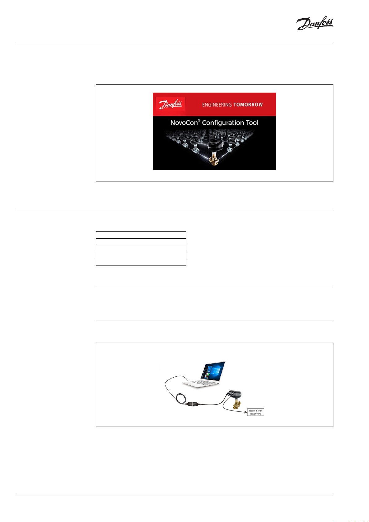
Check if the NovoCon® actuators are already powered by the network, according to specifications.
If you’re using USB Configuration Tool, you should connect actuator as bellow (Figure 2).
Figure 2
NOTE: If you are using the Configuration Tool you need to provide the power from the network of NovoCon®.
In case the actuators are not powered from the network you can connect a 24V AC or DC power supply with a 6,5x2mm
adaptor (+ on the inner connector) to the power connector mounted on the NovoCon® Configuration Tool cable.
2 | AQ340025382575en-010102 © Danfoss | 2020.09
Page 3
Operating Guide NovoCon® Configuration Tool
2.3. NovoCon® M, L or XL
connection to the PC
3. Installation
3.1. Windows driver
installation
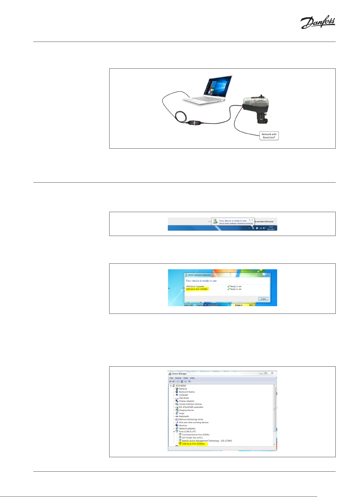
If you’re using new Configuration Tool, you should connect the NovoCon® M, L or XL, the figure shows
a NovoCon® M actuator (Figure 3).
Figure 3
NOTE: If you are using the Configuration Tool you need to provide the power from the network of NovoCon®.
In case the actuators are not powered from the network you can connect a 24V AC or DC power supply with a 6,5x2mm
adaptor (+ on the inner connector) to the power connector mounted on the NovoCon® Configuration Tool cable.
Step 1.
Plug-in the USB cable and you will receive text box message (Figure 4).
Figure 4
Step 2.
Click on the text box message and a new pop-up window will appear (Figure 5).
Figure 5
Please remember the COM port number, because it’s going to be used in subsequent steps. (on Figure
5 the port number is COM36). This is our communication port which is used for communication with
NovoCon®. Click ‘Close’.
Step 3.
If the USB driver is installed properly you can also find the COM port number under Device manager
(Control Panel System and Security Device manager).
Figure 6
AQ340025382575en-010102 | 3© Danfoss | 2020.09
Page 4
Operating Guide NovoCon® Configuration Tool
3.2. Increasing
communication
stability
For better and more stable communication (especially using the Modbus protocol), complete the
following steps:
1. Go to Device Manager in your Windows taskbar searcher.
Figure 7
2. On the Device Manager window, go to the tab »Ports (COM & LPT) « and right click on the port you
have connected your commissioning dongle (USB).
Figure 8
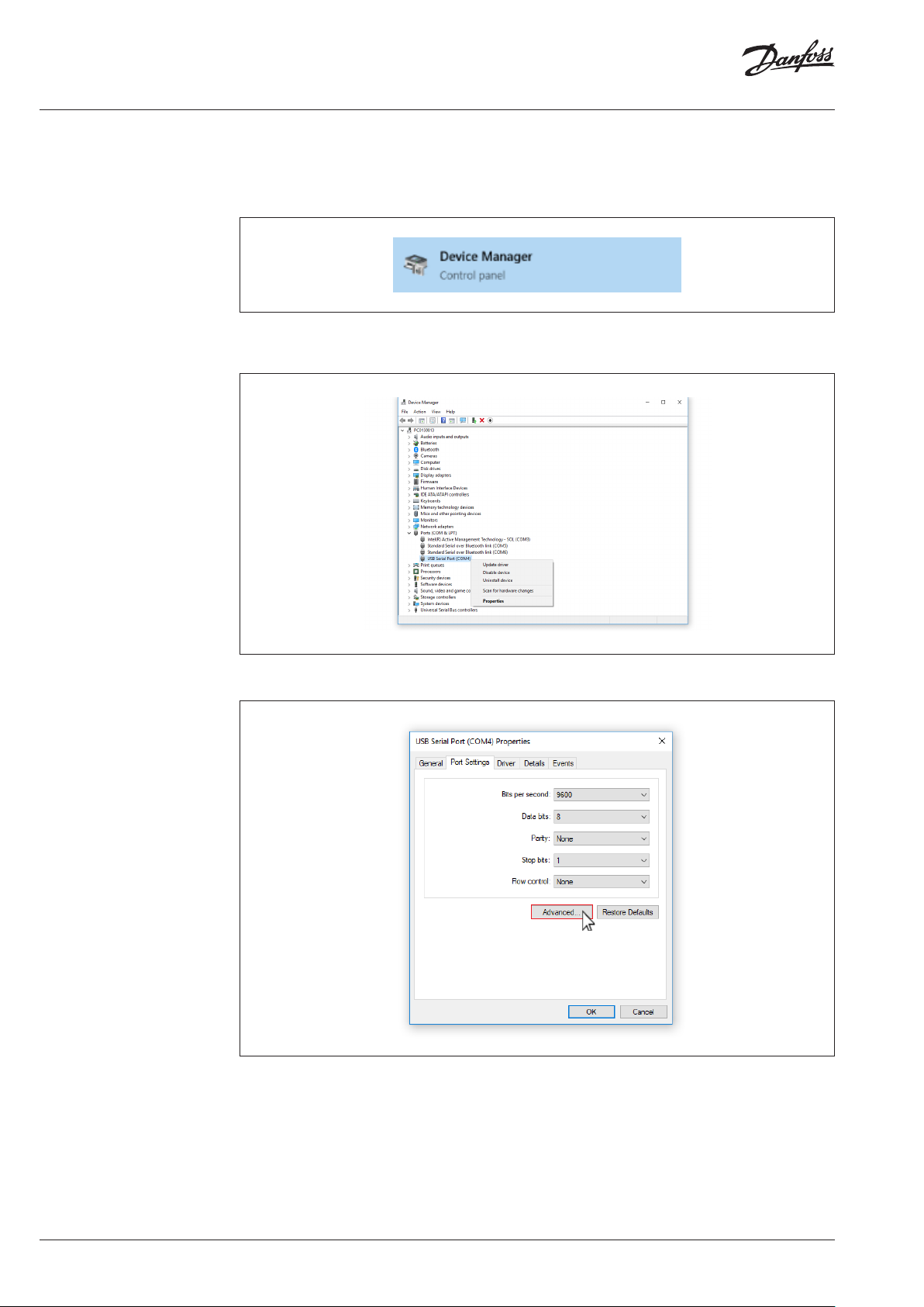
3. In the properties window of your COM port, click »port settings« and then »Advanced«.
Figure 9
4 | AQ340025382575en-010102 © Danfoss | 2020.09
Page 5
Operating Guide NovoCon® Configuration Tool
3.2. Increasing
communication
stability (continuous)
3.3. Setup of
Modbus/BACnet
communication
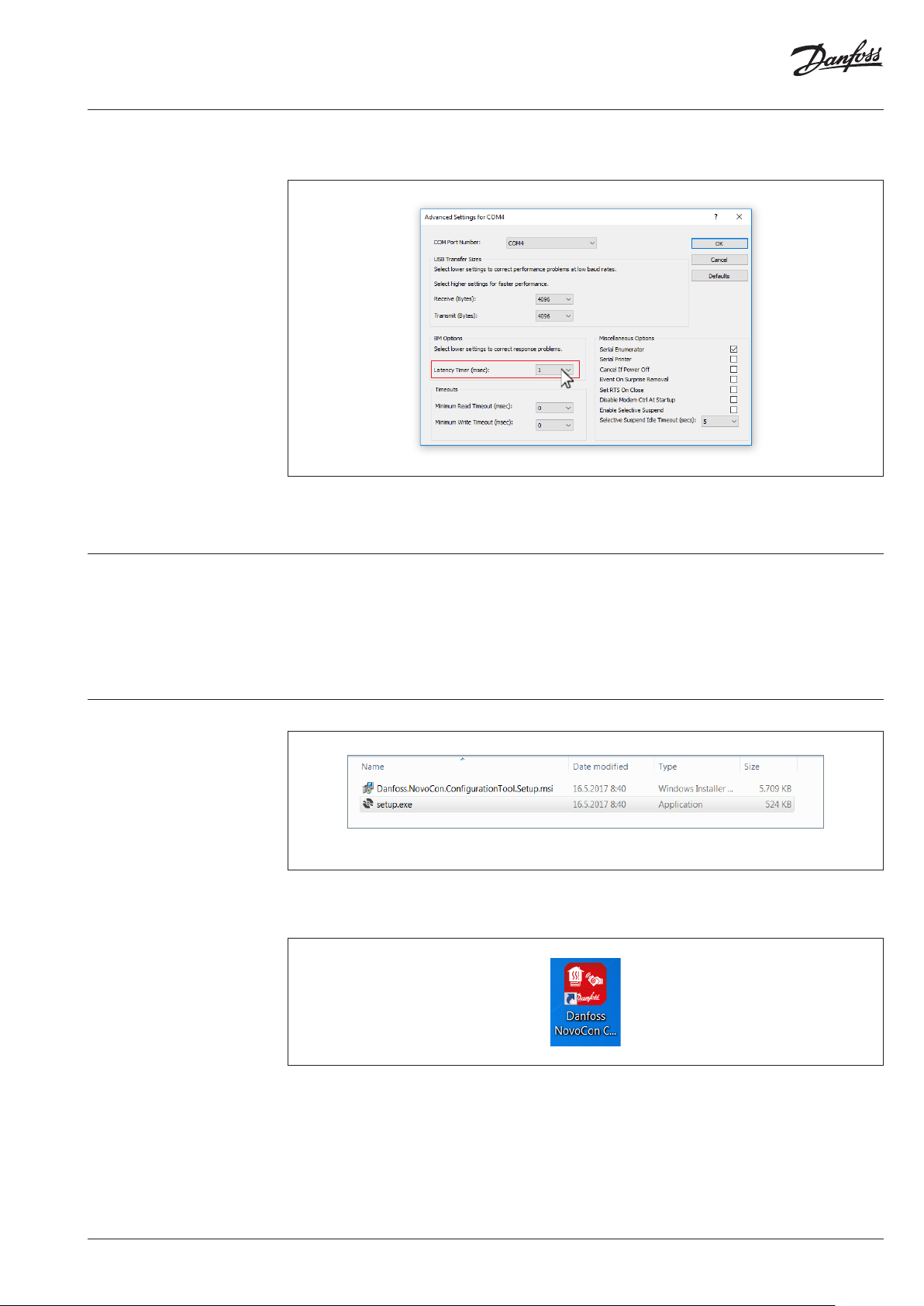
4. In the »Advance Settings for COMX« change »Latency Timer (msec):« parameter to the lowest
possible. In the example below, this is 1.
Figure 10
NOTE: This must be done for each Configuration Tool USB cable that you connect to the PC. If you connect a different
Configuration Tool cable to the PC, this configuration must be performed again.
Either Modbus or BACnet communication protocol must be defined as the communication protocol
for all NovoCon® devices on the network. This is set done manually by turning the 10th DIP switch on
each NovoCon® S (or the 8th.DIP switch for NovoCon® M) to ON (Modbus) or OFF (BACnet). If Modbus
is selected, the Modbus slave ID for each NovoCon® must then be set manually via the DIP switches.
For more information, please refer to NovoCon® data sheets. All devices on the network may be
powered up now.
3.4. Setup of PC Software
Figure 11
Double-click on setup.exe to start the installation. The installer will guide you through the installation
of the NovoCon® Configuration Tool. After installation, the Danfoss NovoCon Configuration Tool icon
should appear on your desktop.
Figure 12
AQ340025382575en-010102 | 5© Danfoss | 2020.09
Page 6

Operating Guide NovoCon® Configuration Tool
4. Modbus user interface
4.1 Connection settings
After double clicking on NovoCon® Configuration Tool icon, the following window will appear:
Figure 13
Step 1.
Protocol: From the radio buttons choose communication protocol.
Step 2.
Port: From the dropdown menu choose the correct COM port. The correct COM port can be checked
by clicking on symbol and Device manager will open.
Step 3.
Baud rate: Set to network Baud rate.
Step 4.
UART: Leave unchanged/default.
Step 5.
Addresses: Set from 1 to the last device address on the network (address 0 is the PC)
Click OK to save the changes. The program should start searching for devices on the network. Every
device that is found within the expected Modbus address range should then appear in the left
column (Figure 14).
There are some key modules/elements in the NovoCon® configuration software tool:
1. Configuration tab
2. Operat ion tab
3. Browser t ab
4. Energy tab
5. Update software tab (Firmware Upgrade)
6. Import CSV Configuration
NOTE: DISABLE sleep or low-power mode while PC is working/communicating with devices. Otherwise uploading
settings or new sof tware installation may interrupt the process!
6 | AQ340025382575en-010102 © Danfoss | 2020.09
Page 7

Operating Guide NovoCon® Configuration Tool
4.2 Configuration tab
Choose one of the NovoCons® from the list. The CONFIGURATION tab will be displayed. The most
frequently used registers can now be set. This tab is used for fast configuration of the valve (Figure 14).
Figure 14
4.3 Operation tab In the OPERATION and ENERGY tab the Application Mode, Energy Management Applications, the
actual flow rate, the temperature inside actuator, the temperatures T1 and T2, as well as alarms can be
set or read. From this tab it is possible to perform quick actions such as putting the actuator in normal,
calibrate, flush and de-air modes. (Figure 15a and Figure 15b).
Figure 15a
Figure 15b
AQ340025382575en-010102 | 7© Danfoss | 2020.09
Page 8

Operating Guide NovoCon® Configuration Tool
4.4 Browser tab
In the BROWSER tab there is a list of all available Modbus registers. The Browser tab allows the user to
configure more advanced settings. Predefined values for registers, that are not grayscale, can be set
(Figure 16).
Figure 16
4.5 Firmware Upgrade tab In the FIRMWARE UPGRADE tab, the selected NovoCons® may be updated to the latest compatible
firmware, or indeed another compatible earlier firmware version. Selected NovoCons® may be
updated individually or multiple at the same time by a broadcasting. This is done by checking the
Broadcast checkbox (Figure 17).
Figure 17
8 | AQ340025382575en-010102 © Danfoss | 2020.09
Page 9

Operating Guide NovoCon® Configuration Tool
4.6 Import CSV
Configuration tab
In the IMPORT CSV CONFIGURATION tab, the selected NovoCons® may be linked with the user’s CSV
pre-settings. After linking and importing the CSV file on for selected NovoCons® the Import report
may be opened or saved. Here it is possible to registers what were successfully written, as well as
errors, warnings etc. (Figure 18).
Figure 18
Excel template files for import of settings, are stored here: C:\Program Files (x86)\Danfoss\NovoCon
Config Tool\CSVImport
File name: NovoConConfigToolBACnetConfiguration_S4.04 and below
- supports NovoCon® S up to SW ver. 4.04
- Valve table AB-QM ISO DN10LF – DN32 and ANSI DN½” LF - DN1¼” HF
File name: NovoConConfigToolBACnetConfiguration_S
- support NovoCon® S from SW ver. 4.10
- Valve table AB-QM 4.0 ISO DN 15LF – DN 32HF, AB-QM ISO DN 10LF – DN 32 and ANSI DN ½” LF DN 1¼” HF
File name: NovoConConfigToolBACnetConfiguration_M
- support NovoCon® M
- Valve table NovoCon AB-QM ISO DN40 – DN100HF
File name: NovoConConfigToolBACnetConfiguration_L_XL
- support NovoCon® L/XL
- Valve table NovoCon AB-QM ISO DN125 – DN250HF
Save the settings in CSV format UTF-8.
Note: Excel template files for importing settings on NovoCons are the same for Modbus and BACnet communication
protocols.
AQ340025382575en-010102 | 9© Danfoss | 2020.09
Page 10
Operating Guide NovoCon® Configuration Tool
4.6 Import CSV
Configuration tab
(continuous)
The following steps will show how to transfer your .csv file to selected NovoCons®:
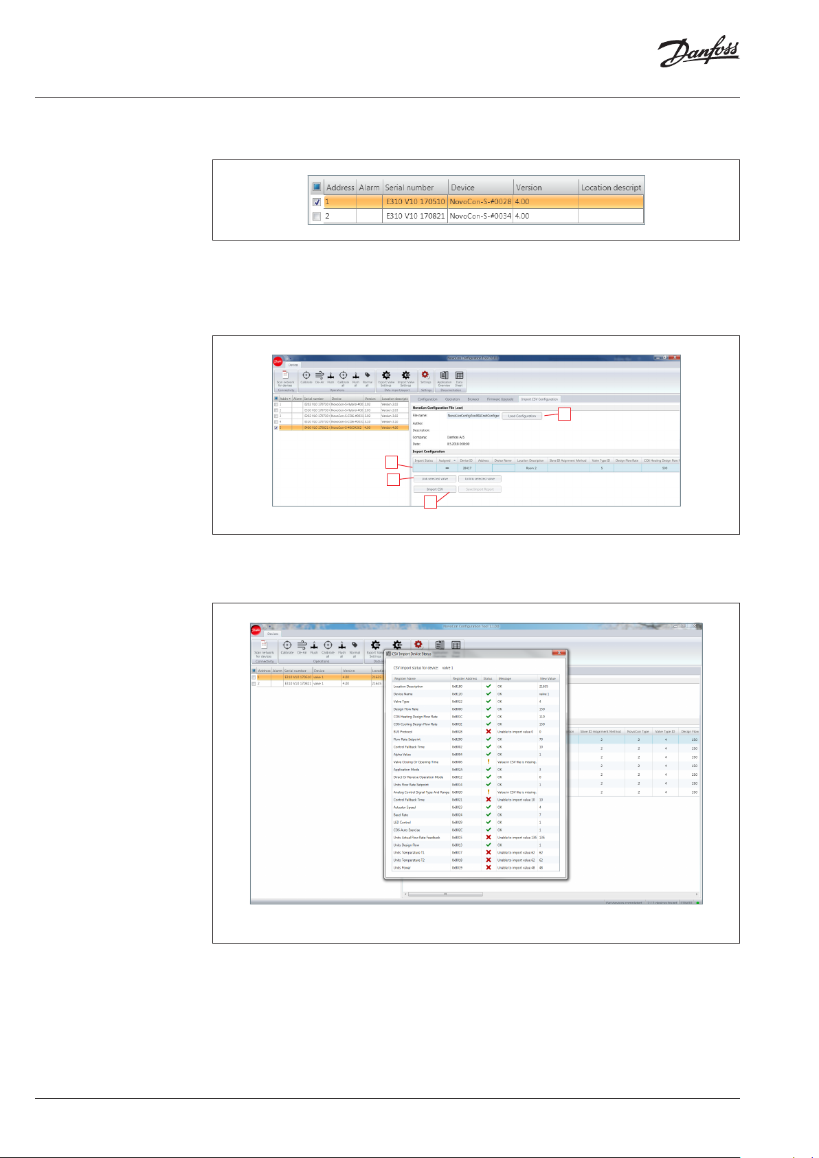
I. Select the NovoCon(s)® in which you want to import the CSV file (figure 19).
Figure 19
II. Select the NovoCon® that you want to import the CSV file (figure 20):
1. Load the CSV file,
2. Select the actuator configuration,
3. Link the configuration to the selected NovoCon®,
4. Import the CSV file to a NovoCon®.
1
2
3
4
Figure 20
III. After importing the CSV file on to the actuator, the Import Report may be checked. This will
show the correct\failure\warning imported data by clicking the exclamation mark in the Import
Status window (figure 21). The report may be saved by clicking Save Import Report.
Figure 21
10 | AQ340025382575en-010102 © Danfoss | 2020.09
Page 11

Operating Guide NovoCon® Configuration Tool
5. BACnet user interface
5.1. Connection settings
After double click on the NovoCon Configuration Tool icon, following window will appear:
Figure 22
Step 1.
Protocol: From the radio buttons choose communication protocol.
Step 2.
Port: From the dropdown menu choose the COM port. The COM port number can be checked it by
clicking on symbol and Device manager will open.
Step 3.
Baud rate: set to the network Baud rate.
Step 4.
Addresses: set from 1 to the last device address on the network (address 0 is the PC)
Click OK to save the changes. The program should start searching for devices on the network. Every
device that is found within the stated BACnet address range should then appear in the left column
(Figure 23).
There are some key modules/elements in the NovoCon® configuration software tool:
1. Configuration tab
2. Operation tab
3. Browser tab
4. Energy tab
5. Update software tab (Firmware Upgrade)
6. Import CSV Configuration
NOTE: DISABLE sleep or low-power mode while the PC is working/communicating with devices. Otherwise uploading
settings or new sof tware installations may be interrupted!
AQ340025382575en-010102 | 11© Danfoss | 2020.09
Page 12

Operating Guide NovoCon® Configuration Tool
5.2. Configuration tab
5.3. Operation tab
Choose one of the NovoCons® from the list. The CONFIGURATION tab will be displayed. The most
frequently used objects can now be set. This tab is used for fast configuration of the valve (Figure 23).
Figure 23
In the OPERATION and ENERGY tab the Application Mode, Energy Management Applications, the
actual flow rate, the temperature inside actuator, the temperatures T1 and T2, as well as alarms can be
set or read. From this tab it is possible to perform quick actions such as putting the actuator in normal,
calibrate, flush and de-air modes. (Figure 24a and Figure 24b).
Figure 24a
Figure 24b
12 | AQ340025382575en-010102 © Danfoss | 2020.09
Page 13

Operating Guide NovoCon® Configuration Tool
5.4. Browser tab
In the BROWSER tab there is a list of all available BACnet objects. The Browser tab allows the user to
configure more advanced settings. Predefined values for objects, that are not grayscale, can be set
(Figure 25).
Figure 25
When moving with the mouse cursor over the objects list, little help pop-ups appear. In the bracket
you get all of the information for the chosen object such as BACnet address (for example MSV:9),
description and description of usage. This is the same information shown in the NovoCon® datasheet.
5.5. Firmware Upgrade tab
In the FIRMWARE UPGRADE tab, the selected NovoCons® may be updated to the latest compatible
firmware, or indeed another compatible earlier firmware version. Selected NovoCons® will be updated
one by one (Figure 25).
Figure 25
AQ340025382575en-010102 | 13© Danfoss | 2020.09
Page 14

Operating Guide NovoCon® Configuration Tool
5.6. Import CSV
Configuration tab
In the IMPORT CSV CONFIGURATION tab, the selected NovoCons® may be linked with the user’s CSV
pre-settings. After linking and importing the CSV file for selected NovoCons® the Import report may
be opened or saved. Here it is possible to registers that were successfully written, as well as errors,
warnings etc. (Figure 26).
Figure 26
When moving with the mouse cursor over the objects list, little help pop-ups appear. In the bracket
you get all of the information for the chosen object such as BACnet address (for example MSV:9),
description and description of usage. This is the same information shown in the NovoCon ® datasheet.
File name: NovoConConfigToolBACnetConfiguration_S4.04 and below
- supports NovoCon® S up to SW ver. 4.04
- Valve table AB-QM ISO DN10LF – DN32 and ANSI DN½” LF - DN1¼” HF
File name: NovoConConfigToolBACnetConfiguration_S
- support NovoCon® S from SW ver. 4.10
- Valve table AB-QM 4.0 ISO DN 15LF – DN 32HF, AB-QM ISO DN 10LF – DN 32 and ANSI DN ½” LF DN 1¼” HF
File name: NovoConConfigToolBACnetConfiguration_M
- support NovoCon® M
- Valve table NovoCon AB-QM ISO DN40 – DN100HF
File name: NovoConConfigToolBACnetConfiguration_L_XL
- support NovoCon® L/XL
- Valve table NovoCon AB-QM ISO DN125 – DN250HF
Save the settings in CSV format UTF-8.
Note: Excel template files for importing settings on NovoCons are the same for Modbus and BACnet communication
protocols.
14 | AQ340025382575en-010102 © Danfoss | 2020.09
Page 15

Operating Guide NovoCon® Configuration Tool
5.6. Import CSV
Configuration tab
(continuous)
Next few steps will show how to transfer your .csv file on selected NovoCon®:
I. Select NovoCon(s)® to which you want import CSV file (figure 27).
Figure 27
II. Select NovoCon® that you want import CSV file (figure 28):
1. Load the CSV file,
2. Select actuator configuration,
3. Link configuration to selected NovoCon®,
4. Import CSV file to a NovoCon®.
Figure 28
III. After importing the CSV file to the actuator, the Import Report may be checked. This will show
the correct\failure\warning imported data by clicking the exclamation mark in the Import Status
window (figure 29). The report may be saved by clicking Save Import Report.
Figure 29
AQ340025382575en-010102 | 15© Danfoss | 2020.09
Page 16

Operating Guide NovoCon® Configuration Tool
© Danfoss | DHS-SRMT/SI | 2020.0916 | AQ340025382575en-010102
 Loading...