

Page 1
Data sheet
Multifunctional Thermostatic Circulation Valve
MTCV - Lead free brass
Introduction
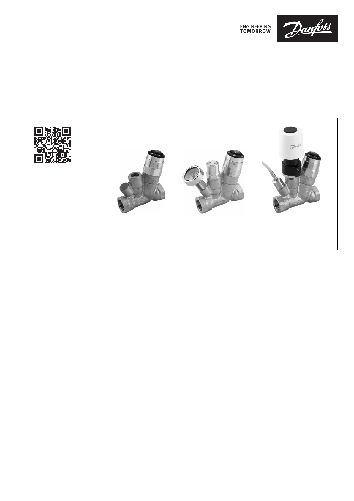
Fig. 1
Basic version - A
The MTCV is a multifunctional thermostatic
balancing valve used in domestic hot water
installations with circulation.
The MTCV provides a thermal balance in hot
water installations by keeping a constant
temperature in the system, thus limiting the flow
in the circulation pipes to the minimum required
level.
To meet the increasing demands placed on the
quality of drinking water, Danfoss MTCV valves
are made from corrosion resistant and Lead Free
materials:
Main functions of the MTCV • Thermostatic balancing of hot water systems
within the temperature range of 35 - 60 °C version A.
• Automatic (self-acting) thermal disinfection
at temperatures above 68°C with safety
protection of the installation to prevent the
temperature rising above 75 °C (automatically
shuts-off circulation flow) - version “B”.
• Automatic disinfection process, electronically
controlled, with the possibility of
programming the disinfection temperature
and duration - version “C”.
•
Automatic flushing of the system by temporarily
lowering the temperature setting to fully open
the MTCV valve for a maximum flow.
• Temperature measurement possibility.
Fig. 2 *
Self-acting version with automatic
disinfection function - “B”
* thermomete r is an accessory
Fig. 3
Version with electronically
controlled disinfection process - “C”
• Valve body made from rg5 bronze material
• Components made from no Lead Brass
• Main cone made from advanced engineering
polymere POM-C.
Simultaneously, the MTCV can realize a
disinfection process by means of 2 features:
• An automatic (self-acting) disinfection
module - thermo-element (fig.2).
• An electronic controller with thermal actuator
TWA and temperature sensors PT1000 (fig.3).
• Preventing of unwanted tampering.
• Constant temperature measurement and
monitoring - version “C”.
• Shut-off function of the circulation riser by
means of optional fittings with a built-in ball
valve.
• Modular upgrading of the MTCV valve during
operation, under pressurized conditions.
• Servicing - when necessary the calibrated
thermo-element can be replaced.
© Danfoss | 2019.04
VD.D3.L2.02 | 1
Page 2
Data sheet MTCV - Lead free brass
Function
Fig. 4 MTCV basic version - A
The MTCV - is a thermostatic self-acting,
proportional valve. A thermo-element (fig. 6
elem. 4) is placed in the valve cone (fig. 6 elem. 3)
to react to temperature changes.
When increases the water temperature above
the set point value, the thermo-element expands
and the valve’s cone moves towards the valve
seat, thus limiting circulation flow.
When decreases the water temperature below
the set point value, the thermo-element will
open the valve and allow more flow in the
circulation pipe. The valve is in equilibrium
(nominal flow = calculated flow) when the water
temperature has reached the value set on the
valve.
The MTCV regulating characteristic is shown in
fig. 13, version A.
When the water temperature is 5 °C higher than
the set point value, the flow through the valve
stops.
A special sealing of the thermo-element
protects it against direct contact with water,
which prolongs the durability of the thermoelement and at the same time secures a precise
regulation.
A safety spring (fig. 6 elem. 6) protects the
thermo-element from being damaged when the
water temperature exceeds the value on the set
point.
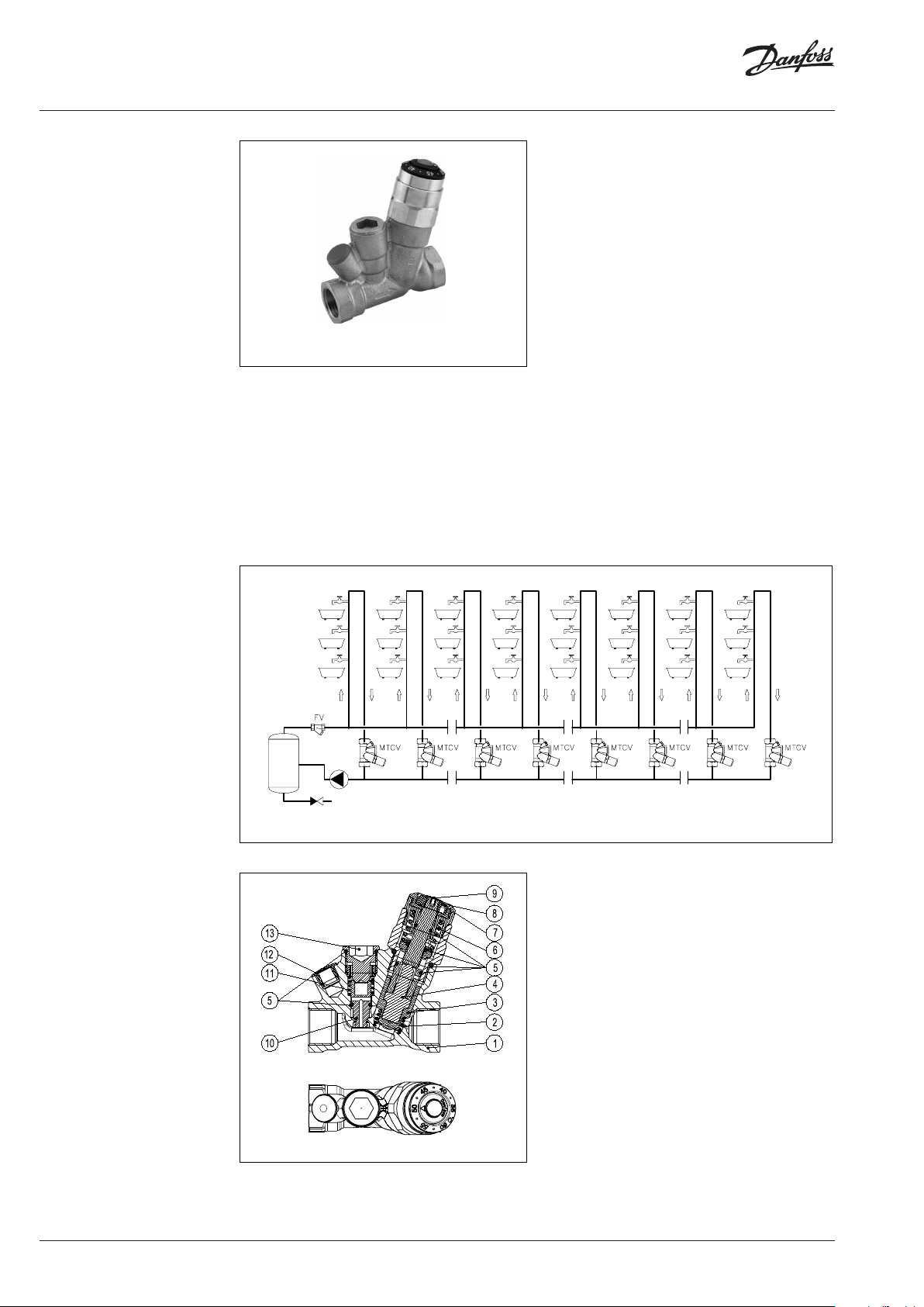
Design
1. Valve body
2. Spring
3. Cone
4. Thermo-element
5. O-ring
6. Safety spring
7. Setting ring
8. Setting knob
9. Plug for covering the setting
10. Cone for disinfection module
11. Safety spring
12. Plug for thermometer
13. Plug for disinfection module
2 | © Danfoss | 2019.04
Fig. 5 Example of MTCV / basic version / placement in domestic hot water system
Fig. 6 Design - basic version - A
VD.D3.L2.02
Page 3
Data sheet MTCV - Lead free brass
TVM-W
TVM-W
TVM-W
TVM-W
TVM-W
TVM-W
TVM-W
TVM-W
TVM-W
TVM-W
TVM-W
TVM-W
TVM-W
TVM-W
TVM-W
TVM-W
TVM-W
TVM-W
FV
S
S
M
S
M
S
ECL...
MTCV MTCV
MTCV MTCV MTCV MTCV
Function
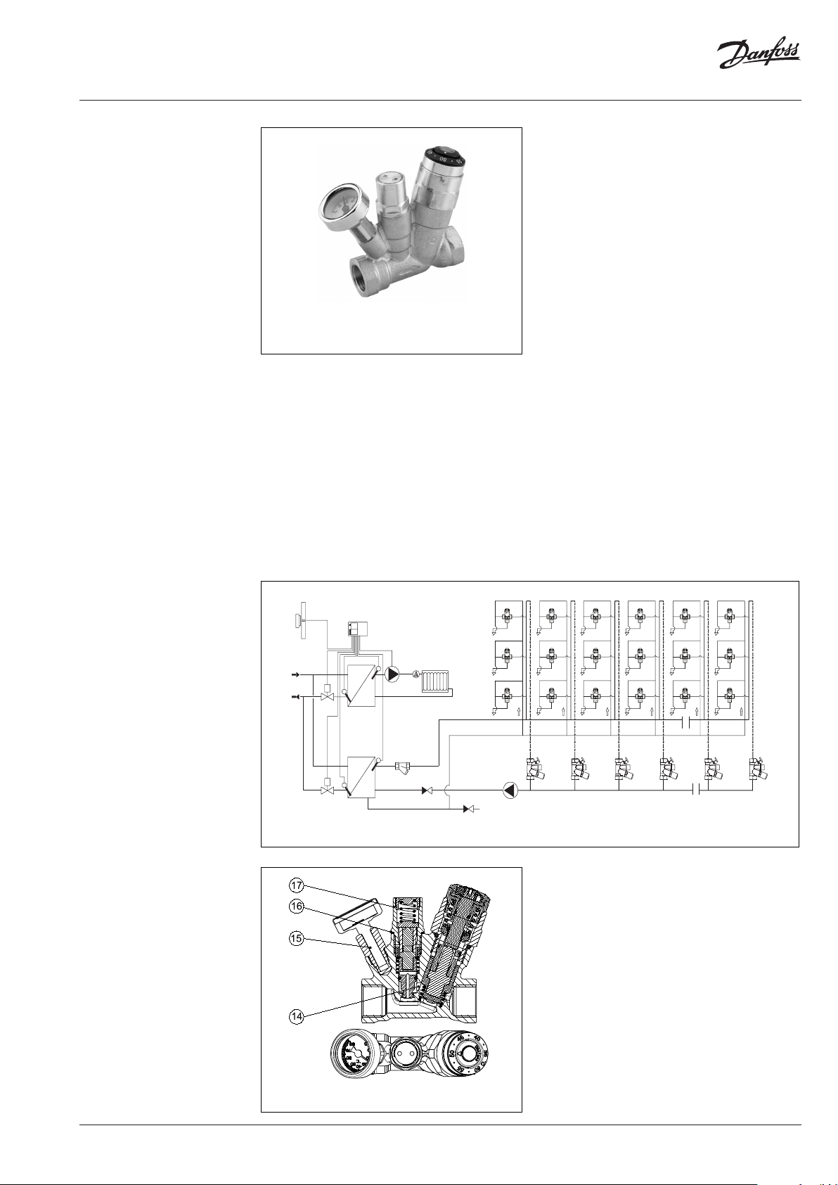
Fig.7 MTCV self-acting version with automatic thermal
disinfection function - B
* thermomete r is accessory
The MTCV standard version - A can easily and
quickly be upgraded to the thermal disinfection
function against the Legionella bacteria in hot
water systems.
After removing the plug from the disinfection
plug (fig. 6 elem. 13)-(this can be done during
working conditions, under pressure) the
thermostatic disinfection module can be
mounted (fig. 9 elem. 17).
The disinfection module will control the flow
according to its regulating characteristics,
(fig. 13, version B) thus performing a thermal
disinfection of the hot water installation.
The mounted disinfection module automatically
opens a by-pass of Kv min = 0.15 m3/h, which
allows flow for the disinfection. In the A version
of the MTCV this by-pass is always closed in
order to avoid sedimentation of dirt and calcium.
The MTCV can thus be upgraded with the
disinfection module even after a long period of
working in the A version without risking blocking
the bypass.
The regulation module in basic version A works
within the temperature range 35-60 °C. When
the temperature of the hot water increases
above 65°C the disinfection process starts meaning the flow through the main seat of the
MTCV valve stops and the bypass opens for the
“disinfection flow”. The regulating function is
now performed by the disinfection module,
which opens the bypass when the temperature is
above 65 °C.
The disinfection process is performed until a
temperature of 70 °C is reached. When the hot
water temperature is increased further, the flow
through the disinfection bypass is reduced (the
process of thermal balancing of the installation
during disinfection) and when reaching 75 °C
the flow stops. This is to protect the hot water
installation against corrosion and sedimentation
of calcium as well as to lower the risk of scalding.
A thermometer can optionally be mounted in both
version A and B in order to measure and control
the temperature of the circulating hot water.
Design
1-13 As described in fig. 6
14 Bypass for disinfection
15 Thermometer
16 Gasket Cu
17 Disinfecting module
VD.D3.L2.02
Fig. 8 Scheme of hot water installation with circulation - self acting version.
Fig. 9 Design - self-acting version with automatic
thermal disinfection function - B
© Danfoss | 2019.04 | 3
Page 4
Data sheet MTCV - Lead free brass
Function
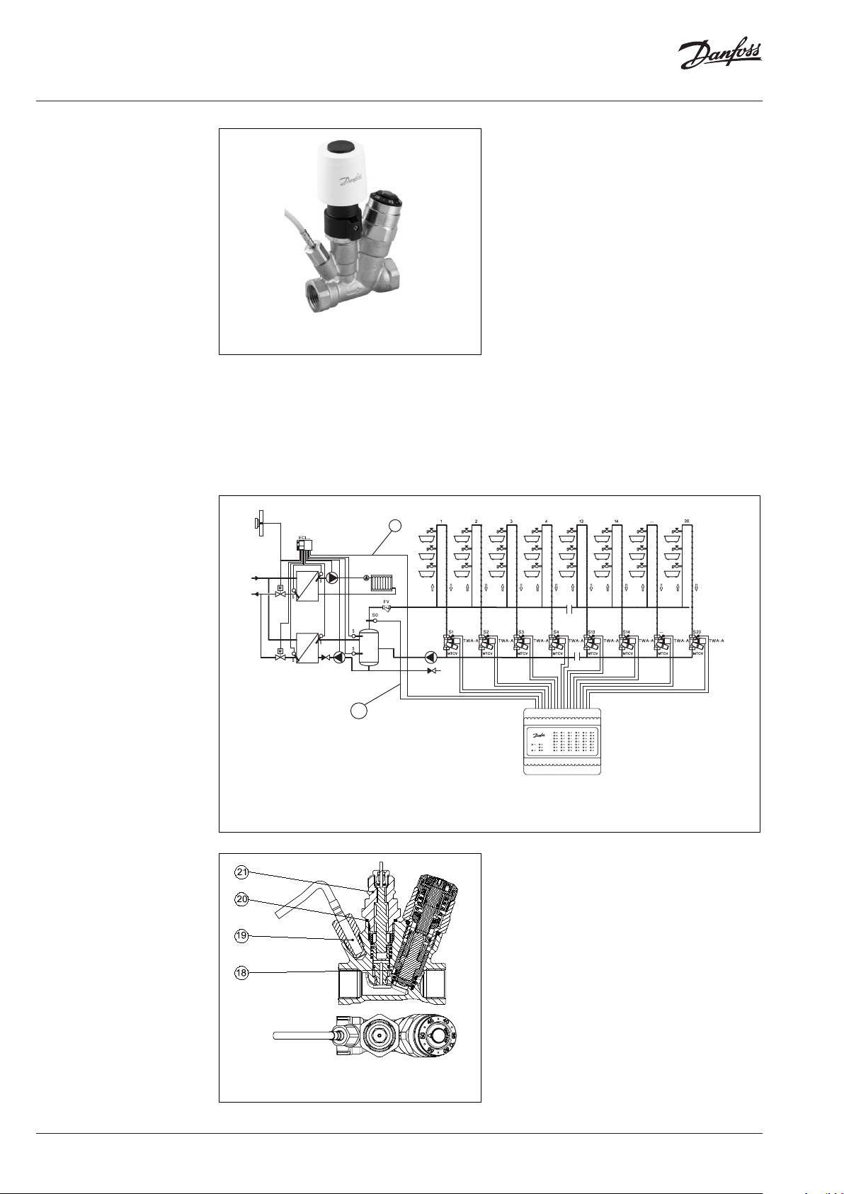
Fi g.10 Version with electronically controlled
disinfection process - C
The MTCV version “A” and “B” can be upgraded
to an electronic regulated disinfection process
(version C).
After removing the disinfection plug (fig. 6
elem. 13) the adapter can be mounted (fig. 12
elem. 21) and the thermo actuator TWA can be
mounted.
B
A temperature sensor PT 1000 has to be mounted
in the thermometer head (fig. 12 elem. 19).
Thermo-actuator and sensor are connected to
the electronic regulator CCR2+ which allows
an efficient and effective disinfection process
in each circulation riser. The main regulation
module works within the temperature range
35-60 °C. When the disinfection process/thermalwater treatment starts CCR2+ controls the flow
through MTCV via thermo-actuators TWA.
Benefits of an electronic regulated disinfection
process with CCR2+ are:
• Providing full control over the disinfection
process in each individual riser.
• Optimisation of total disinfection time.
• Optional choice of temperature for the
disinfection.
• Optional choice of time for the disinfection.
• On-line measurement and monitoring of the
water temperature in each individual riser.
• Enabling the possibility of connecting to the
controller in the heat substation or boiler
room (i.e. Danfoss ECL) or to a BMS (Modbus).
Design
1-13 As described in fig. 6
18 Bypass; (position closed)
19 Temperature sensor PT 1000
20 Gasket Cu
21 Adapter to connect thermo-
actuator TWA
*
A
Fi g. 11 - scheme of installation for disinfection and registration temperature
A) in dependent system (only se nsor S0 needed)
B) depende nt system (sensor S0 and connectio n to weather or another control n eeded)
4 | © Danfoss | 2019.04
Fi g.12 Version with electronically controlled
disinfection process - C
VD.D3.L2.02
Page 5

Data sheet MTCV - Lead free brass
Technical data Max. working pressure ........................................ 10 bar
Test pressure ...........................................................16 bar
Max. flow temperature .......................................100 °C
kVS at 20 °C:
- DN20 ............................................................ 1.8 m3/h
- D N15 .............................................................1. 5 m3/h
Hysteresis .................................................................... 1.5 K
Ordering
Valve - basic ve rsion A Code No.
DN 15 003Z4 515
DN 20 003Z4520
Accessories and spare parts
Accessory Comments
Thermostatic disinfection module - B DN 15/DN 20
Fittings with shut-of f ball valve
(for allen key 5 mm), DN 15
Thermometer with adapter DN 15/DN 20
Socket for ESMB PT1000 DN 15/DN 20
Adapter for thermo-actuator DN 15/DN 20
Material of parts in contact with water:
Valve body ...................................................................Rg5
Spring housing, etc. ............Cuphin alloy (CW724R)
O-rings ...................................................................... EPDM
Spring, bypass cones ........................... Stainless steel
Cone .......................... POM-C (Acetal Homopolymer)
Code No.
003 Z2021
G ½ × Rp ½
G ¾ × Rp ¾ 003 Z1028
003 Z1027
003 Z1023
003 Z1024
003 Z1022
CCR2+ Controller also see enclosure VD.D3.K1.02 003 Z3851
CCR+ Slave Unit also see enclosure VD.D3.K1.02 003Z38 52
Temperature sensor ESMB Universal
Temperature sensor ESMC contact 08 7N 0011
Fittings for soldering Cu 15 mm
Fittings for soldering Cu 18 mm
Fittings for soldering Cu 22 mm
Fittings for soldering Cu 28 mm
Thermoactuator TWA-A/NC, 24V also see enclosure VD.57.U4.02 088H3110
also see enclosure VD.D3.K1.02
DN 15
int. R 1/2”
DN 20
int. R 3/4”
08 7B11 84
003Z1034
003Z1035
003Z1039
003 Z1040
VD.D3.L2.02
© Danfoss | 2019.04 | 5
Page 6

Data sheet MTCV - Lead free brass
25 35 45 55 65 75 85
K
vs
K
vmin
K
vdis
basic
disinfection
version B
version
C
vri
n A
temperature ˚C
presetting 50 ˚C
flow
Regulating characteristics
Fig.13 The MTCV regulating characteristics
Kv
min
Main function setting
• Basic version A
• Version B:
Kv
= 0.15 m3/h - min. flow through the
min
bypass when main regulation module
is closed.
*Kv
*Kv
= 0.60 m3/h for DN 20,
dis
= 0.50 m3/h for DN 15 - max. flow of the
dis
disinfection process by a temperature
of 70 °C.
Setting ring
1
Ring with a reference point
2
Plastic cover - unwanted
3
tampering protection
Hole for screwdriver
4
Temperature setting screw -
5
Allen-key 2.5 mm
References temperature
6
setting point
4
Fig.14 MTCV setting of the temperature
Temperature range: 35-60 °C
MTCV´s factory pre-setting 50 °C
The temperature setting can be made after
removing the plastic cover (3), by lifting it with a
screwdriver using the hole (4). The temperature
setting screw (5) must be turned with an allenkey to match the wanted temperature on the
scale with the reference point. The plastic cover
(3) must be pressed back into place after the
setting has been made.
• Version C:
* Kv
= 0.60 m3/h for DN 20 and DN 15 -
dis
flow through the MTCV when the
disinfection module is fully opened
(regulation at thermo-actuator TWA-NC).
* Kv
- Kv during disinfection process
dis
3
1
5
2
6
It is recommended to control the set temperature
with a thermometer. The temperature of the hot
water from the last tapping point on the riser
must be measured*. The difference between the
measured temperature at the last tapping point
and the temperature set on the MTCV is due to
heat losses in the circulation pipe between the
MTCV and the tapping point.
* where T VM valves (thermostatic mixing val ves) are installed t he
temperature mu st be measured before the T VM valve.
6 | © Danfoss | 2019.04
VD.D3.L2.02
Page 7

Data sheet MTCV - Lead free brass
0
10
20
30
40
50
60
70
0 0.20 0.40 0.60 0.80 1.00 1.20 1.40 1.60
Flow temperature ˚C
setting
at 60 ˚C
setting at 50 ˚C
setting
at 35 ˚C
Kv (m
3
/h)
55
60
65
70
75
80
0 0.10 0.20 0.30 0.40 0.500 0.60
Flow temperature ˚C
Kv (m3/h)
version B
version C
Setting procedure
Pressure and flow chart
MTCV - DN 15
The required temperature setting of the MTCV
depends on the required temperature at the last
tap and the heat losses from the tap to MTCV in
the same riser.
Example:
Required temperature at the last tap: 48 °C
Heat losses from the last tap to the MTCV: 3 K
Differential pressure 1 bar, DN 15
Required:
correct setting of MTCV
Solution:
Correct setting of MTCV: 48 - 3 = 45 °C
Note:
After new setting use the thermometer to check if
the required temperature at the tap is reached and
correct the MTCV setting accordingly.
Fig. 15
Table 1
preset preset preset preset preset preset
60 °C 55 °C 50 °C 45 °C 40 °C 35 °C
65 60 55 50 45 40 0
62.5 57. 5 52.5 47. 5 42. 5 37. 5 0.238
60 55 50 45 40 35 0.427
57. 5 52.5 47. 5 42. 5 37. 5 32.5 0.632
55 50 45 40 35 30 0.795
52.5 47. 5 42. 5 37. 5 32.5 0.963
50 45 40 35 30 1.087
47. 5 42.5 37.5 32.5 1.202
45 40 35 30 1.28 3
42.5 37. 5 32.5 1.351
Flow temperature °C
40 35 30 1.394
37. 5 32.5 1.437
35 30 1.469
32.5 1.500
30 1.500
Differential pressure 1 bar, DN 15 - disinfection process
Fig. 16
kv
(m3/h)
VD.D3.L2.02
© Danfoss | 2019.04 | 7
Page 8

Data sheet MTCV - Lead free brass
70
2.00
Flow temperature ˚C
80
0.70
Flow temperature ˚C
Differential pressure 1 bar, DN 20Pressure and flow chart
MTCV - DN 20
60
Fi g. 17
Tab le 2
Flow temperature °C
50
40
30
20
10
0
0 0.20 0.40 0.60 0.80 1.00 1.20 1.40 1.60 1.80
preset preset preset preset preset preset
60 °C 55 °C 50 °C 45 °C 40 °C 35 °C
65 60 55 50 45 40 0
62.5 57. 5 52.5 47. 5 42. 5 37. 5 0. 251
60 55 50 45 40 35 0. 442
57. 5 52.5 47. 5 42. 5 37. 5 32.5 0.645
55 50 45 40 35 30 0.828
52.5 47. 5 42. 5 37. 5 32.5 1.000
50 45 40 35 30 1.164
47. 5 42.5 37.5 32.5 1.32 2
45 40 35 30 1.46 2
42.5 37. 5 32.5 1.577
40 35 30 1.667
37. 5 32.5 1.733
35 30 1.753
32.5 1.761
30 1.761
Ex. 1
0.366
setting at 50 ˚C
setting
at 35 ˚C
Kv (m
3
/h)
setting
at 60 ˚C
kv
(m3/h)
Differential pressure 1 bar, DN 20 - disinfection process
75
70
65
60
55
0 0.10 0.20 0.30 0.40 0.50 0.60
Fig . 18
Kv m3/h
version B
version C
8 | © Danfoss | 2019.04
VD.D3.L2.02
Page 9
Data sheet MTCV - Lead free brass
p
.
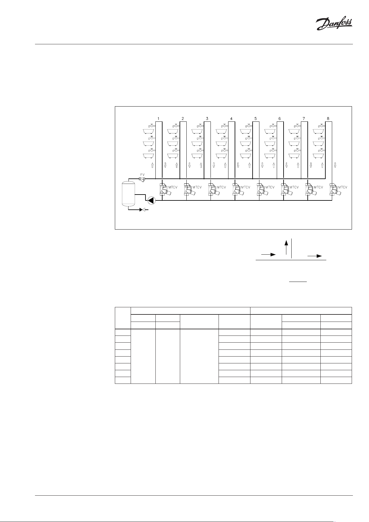
Example of calculation
Example:
The calculation is done for a
3-storey building with 8 risers.
The following assumptions were
used in order to simplif y
calculation:
• Heat losses per meter of the
pipe,
q1 =10 W/m *
* during calcula tion it is required to
calculate heat lo sses according to the
country-specific standards.
Usually the calculated heat loses are dependent
on :
- The dimension of the pipe
- The materials used in insulations
- The ambient temperature where the pipe is
located
- The efficiency and condition of insulation
Fig. 19 Scheme of installation
• Inlet of hot water temperature, T
• Temperature drop through the system,
= 55 °C
sup
∆T= 5 K
• Distance between risers, L = 10 m
• Height of the risers, l = 10 m
• Installation scheme as shown below:
I Basic operation
o
˙
V
Calculation:
• calculation of heat losses in each riser
(Qr) and header (Qh)
Qr = l riser x q = ( 10 + 10 ) x 10 = 200 W
Qh = l horiz. x q = 10 x 10= 100 W
• The table 3 shows the results of the
calculations:
˙
V
c
&
V+=
c
˙
V
p
V
o
.o.
VV
Tab le 3
heat losses
riser
In risers In header
Qr (W) Qh (W ) Vo (l/h) Vc (l /h)
1
2 2100 0.09 38 376
3 1800 0.1 40 339
4 150 0 0 .12 43 299
200 100 300
5 120 0 0 .14 47 256
6 900 0.18 52 210
7 600 0.25 63 157
8 300 0.4 94 94
Total in each part
(W)
ΣQ total
(W)
2400 - 36 412
Factor risers
Flow in each part Total f low
VD.D3.L2.02
© Danfoss | 2019.04 | 9
Page 10

Data sheet MTCV - Lead free brass
V
&
V
&
Example of calculation
(continuous)
• The total flow in the hot water circulation
system is calculated using formula:
&
Q
&
V
∑
=
Δ
tcr
hww
ΣQ - total heat loses in installation, (kW)
thus:
total
&
V
C
4.2
=
518.41
××
= 0.114 l/s = 412 l/h
The total flow in hot water circulation system
is: 412 l/h - the circulation pump shall be sized
for this flow.
• The flow in each riser is calculated using
formula:
Flow in the riser number 1:
Q
&&
VV
o
×=
co
QQ
+
po
thus:
1
&
412V
0
200
×=
2100200
+
= 35.84 l/h ≅36 l/h
Flow in remaining risers should be calculated
in the same way.
• The pressure drop in the system
Following assumptions were made to simplify
calculation:
- Linear pressure drop, p
(Linear pressure is the same for all pipes)
= 60 Pa/m
l
- Local pressure drop is equal to 33 % of
total linear pressure drop, pr = 0.33 p
thus:
pr = 0.33 × 60 = 19.8 Pa/m ≅ 20 Pa/m
l
- For the calculation used
p
= pr + pl = 60 + 20 = 80 Pa/m
basic
- Local pressure drop across the MTCV is
calculated on the basis of:
⎛
⎜
=
Δp
MTCV
⎜
⎝
Kv
⎞
×
V01.0
0
⎟
⎟
⎠
2
&
where:
Kv - according to fig. 19 page 10
in this case
Kv = 0.366 m3/h for preset 50 °C
- flow through the MTCV at the flow
0
temperature 50 °C (l/h)
• When designed flow have been calculated,
use the fig. 17 on page 9.
Please note:
during pressure drop calculation across the valve
the temperature of circulation water has to be
observed. MTCV - Multifunction Thermostatic
Circulation Valve has variable Kv value which is
dependent on two values: the preset temperature
and the temperature of the flow temperature.
When the
across MTCV is calculated using the following
and Kv are known, the pressure drop
0
formula:
⎛
⎜
=
Δp
MTCV
⎜
⎝
Kv
⎞
×
V01.0
0
⎟
⎟
⎠
2
&
thus:
2
9401.0
×
Δp
∆p
⎛
=
⎜
MTCV
⎝
MTCV
⎞
⎟
366.0
⎠
kPa 6.59
=
= (0.01 x 94 / 0.366 )2 = 6.59 kPa
• Differential pressure across the pump:
Where:
∆p
*p
*p
pump
= ∆p
circuit
+ ∆p
MTCV
= 14.4 + 6.59 = 21 kPa
- pressure drop in critical circuit
circuit
(table 4)
- includes pressure drop across all
pump
devices in circulation installation like:
boiler, strainer etc.
10 | © Danfoss | 2019.04
Tab le 4
riser
In risers
(kPa)
1
2 12. 8 38 1. 07
3 11. 2 40 1.19
4 9.6 43 1.38
5 8.0 47 1.64
6 6.4 52 2.01
7 4.8 63 2.96
8 3.2 94 6.59
1.6 1.6
pressure drop across the MTCV
In heade r
(kPa)
p
circuit
(kPa)
14.4 36 0.97
V0-flow
(l/h)
∆mMTCV pressure drop
(kPa)
Total pressure
pump
(kPa)
21
VD.D3.L2.02
Page 11

Data sheet MTCV - Lead free brass
V
&
V
&
Example of calculation
(continuous)
II Disinfection
The heat losses and pressure drop should be
calculated according to new conditions.
- inlet hot water temperature during
disinfection T
- ambient temperature *T
(*T
- according to standard and norm
amb
obligatory)
= 70 °C
dis
amb
= 20 °C
thus:
Δp
MTCV
Due to lower flow comparing to basic
condition (412 l/h), pressure drop in the
installation, p
Δp
where :
1. The heat losses are calculated from the
formula:
q1 = Kj x l x ∆T1 → Kj x l = q1/∆T1
for basic process
q2 = Kj x l x ∆T2 → Kj x l = q2 /∆T2
for disinfection process
Thus :
⎛
Δ
T
2
⎜
=
=
qq
q
12
1
⎜
Δ
T
1
⎝
⎞
−
TT
ambdis
⎟
⎟
−
TT
ambsup
⎠
for given case:
C 20C 70
°−°
=
2
⎜
⎝
⎛
(W/m) 10q
⎞
W/m 14.3
=
⎟
C 20C 55
°−°
⎠
In this case during disinfection process heat
losses increase for around 43 %.
w - velocity of the water (m/s)
By comparing conditions during basic
operation and disinfection one can estimate:
pp ×=
where :
V
- disinfection flow (l/h)
dis
VC - basic flow (l/h)
Thus:
- for first part of installation
1
80p
dis
This calculation should be done for all
critical circuit. The table 5 shows the result of
calculation.
2. Required flow
Due to sequence disinfection process (step by
step) only critical circuit should be calculated.
For given case:
Q
= Qr + Qh
dis
Q
= ((10+10) + (8 × 10)) × 14.3 W/m =
dis
1430 W = 1.43 kW
The flow:
1.43
&
V
=
dis
54.18
×
==
l/h 246l/s 0.0684
3. The required pressure
The required pressure during the disinfection
For the critical circuit:
p
dis(circuit)
+ 2.20 + 3.93 + 21.92 = 32.70 kPa
p
= 32.70 + 16.81 = 49.51 kPa
dispump
= p
The pump should be chosen to cover both
requirements:
• basic operation,
= 412 l/h and p
0
• disinfection operation
= 246 l/h and P
0
process should be checked
p
dispump
where:
Δp
MTCV
= p
=
dis(circuit)
⎛
⎜
⎜
⎝
Kv
×
+ ∆p
&
V01.0
0
MTCV
2
⎞
⎟
⎟
⎠
Tab le 5
pressure drop the circuit during disinfection process
flow (l/h)
basic disinfection
412 246 29
376 246 34 0.68
339 246 42 0.84
299 246 54 1.08
256 246 74 1.4 8
210 246 110 2.20
157 246 196 3.93
94 246 548 40 21.92
new pressure drop
(Pa/m)
length
(m)
20
2
×
2460.01
0.6
⎞
⎟
⎠
kPa 16.81
=
should be recalculated.
2
V
dis
2
V
c
2
⎞
Pa/m 29
=
⎟
⎠
⎛
=
⎜
⎝
circuit
2
w
2
basicdis
246
⎛
×=
⎜
412
⎝
= 0.57 + 0.68 + 0.84 + 1.08 + 1.48
+ ∆p
dis(circuit)
pressure drop
(kPa)
0.57
∑ 32.70
MTCV
= 21 kPa
pump
= 49.51 kPa
pump
Total pressure drop
in critical circuit
32.70
VD.D3.L2.02
© Danfoss | 2019.04 | 11
Page 12

Danfos
produc
Al
Danfoss A/S
Heating Segment • heating
Data sheet MTCV - Lead free brass
Dimensions
Internal thread
DN 15
DN 20
Fig. 20
A a H H1 L L1
IS O 7/1 mm
Rp ⁄ Rp ⁄ 79 129 75 215 0.56
Rp ⁄ Rp ⁄ 92 12 9 80 230 0.63
Weight
(kg)
s can accept no responsibility for possible errors in catalogues, brochures and o ther printed material. Danfoss reserves the right to alter its products w ithout notice. This also applies to
ts already on order provided that such alterations can be m ade without subsequential changes being necessary in specications already agreed.
l trademarks in this material are p roperty of the respective companies. Danfoss and all D anfoss logotypes are trademarks of Danfoss A/S. All rights reser ved.
12 | © Danfoss | DHS-SRMT/SI | 2019.04
.danfoss.com • +45 7488 2222 • E-Mail: heating@danfoss.com
VD.D3.L2.02
 Loading...