

Page 1
Operating Guide
VLT® Multiaxis Servo Drive MSD 510 System
Page 2

Page 3

ContentsOperating Guide | VLT® Multiaxis Servo Drive MSD 510 System
Contents
1 Introduction 14
1.1 Purpose of the Operating Guide 14
1.2 Additional Resources 14
1.3 Copyright 14
1.4 Approvals and Certifications 15
1.5 Areas of Application 16
1.6 Software 16
1.7 Terminology 17
2 Safety 18
2.1 Safety Symbols 18
2.2 Safety Instructions and Precautions 18
2.2.1 Operational Safety 19
2.3 Important Safety Warnings 19
2.4 Qualified Personnel 21
2.5 Due Diligence 21
2.6 Intended Use 21
2.6.1 Prohibited Application Areas 22
2.7 Forseeable Misuse 22
2.8 Service and Support 22
3 System Description 23
3.1 Overview of the VLT® Multiaxis Servo Drive System MSD 510 23
3.1.1 Application Examples 24
3.1.2 Maximum Number of Modules 25
3.2 Power Supply Module PSM 510 25
3.2.1 Overview 25
3.2.2 Connectors on the Top of PSM 510 27
3.2.3 Connectors on the Bottom of PSM 510 27
3.3 Servo Drive Module SDM 511/SDM 512 27
3.3.1 Overview 27
3.3.2 SDM 511/SDM 512 Types 28
3.3.3 Components 29
3.3.3.1 Cooling 29
3.3.4 Connectors on SDM 511 29
3.3.4.1 Connectors on the Top of SDM 511 30
3.3.4.2 Connectors on the Bottom of SDM 511 30
3.3.5 Connectors on SDM 512 31
3.3.5.1 Connectors on the Top of SDM 512 31
3.3.5.2 Connectors on the Bottom of SDM 512 32
AQ262450196490en-000101 / | 3Danfoss A/S © 2019.10
Page 4

ContentsOperating Guide | VLT® Multiaxis Servo Drive MSD 510 System
3.4 Decentral Access Module DAM 510 32
3.4.1 Overview 32
3.4.2 Connectors on the Top of DAM 510 33
3.4.3 Connectors on the Bottom of DAM 510 34
3.5 Auxiliary Capacitors Module ACM 510 34
3.5.1 Overview 34
3.5.2 Connectors on the Top of ACM 510 35
3.6 Expansion Module EXM 510 36
3.7 Local Control Panel (LCP) 37
3.7.1 Overview of the Local Control Panel 37
3.7.2 Layout of the Local Control Panel 37
3.7.2.1 A: Display Area 37
3.7.2.2 B: Display menu keys 40
3.7.2.3 C: Navigation keys and indicator lights (LEDs) 41
3.7.2.4 D: Operation keys and reset 41
3.8 Cables 42
3.8.1 Hybrid Cable 42
3.8.2 Ethernet Cable 42
3.8.3 LCP Cable 43
3.9 Cable Layout and Routing 43
3.9.1 Maximum Cable Lengths 43
3.9.2 Wiring of Output Filter 44
3.9.3 Standard Cabling Concept for 2 Decentral Access Modules (DAM 510) 44
3.10 Software 44
3.11 Fieldbus 45
3.11.1 EtherCAT® 45
3.11.2 Ethernet POWERLINK® 47
3.11.3 PROFINET® 47
4 Mechanical Installation 48
4.1 Items Supplied 48
4.2 Transport 48
4.3 Inspection on Receipt 48
4.4 Safety Measures during Installation 48
4.5 Installation Environment 49
4.5.1 System Components 49
4.6 Preparation for Installation 49
4.6.1 System Modules 49
4.6.2 Drilling Templates 50
4.7 Installation Procedure 50
4.7.1 Space Requirements for System Modules 50
4.7.2 Installation Aids and Tools Required 52
AQ262450196490en-000101 /4 | Danfoss A/S © 2019.10
Page 5

ContentsOperating Guide | VLT® Multiaxis Servo Drive MSD 510 System
4.7.3 Fitting Instructions for System Modules 52
5 Electrical Installation 57
5.1 Warnings for Electrical Installation 57
5.2 Electrical Environmental Conditions 57
5.3 Grounding 58
5.3.1 Grounding for Electrical Safety 58
5.3.2 Grounding for EMC-Compliant Installation 60
5.4 Mains Supply Requirements 61
5.4.1 Fuses 61
5.4.2 Circuit Breakers 62
5.5 Auxiliary Supply Requirements 62
5.5.1 Fuses 62
5.6 Safety Supply Requirements 62
5.7 UL Requirements 63
5.8 Connecting the Servo Drive Module SDM 511/SDM 512 64
5.8.1 Connecting the Motor Cable 64
5.8.2 Connecting the Brake/Thermistor Cable 66
5.8.3 Connecting the Cables on the Top of the Servo Drive Modules SDM 511/SDM 512 67
5.9 Connecting the Power Supply Module PSM 510 68
5.9.1 AC Line Choke 68
5.9.1.1 Connecting 1 PSM 510 to the AC Choke 68
5.9.1.2 Connecting 2 PSM 510 Modules to the AC Choke 69
5.9.1.3 Connecting 2 PSM 510 Modules to the AC Choke with System Splitting 70
5.9.2 Connecting the Cables on the Power Supply Module PSM 510 71
5.9.2.1 Connecting the Cables on the Top of the Power Supply Module PSM 510 71
5.9.2.2 Connecting the Cables on the Bottom of the Power Supply Module PSM 510 72
5.10 Connecting the Decentral Access Module (DAM 510) 73
5.10.1 Connecting the Cables on the Top of the Decentral Access Module DAM 510 73
5.10.2 Connecting the Feed-In Cable 73
5.11 Connecting the Auxiliary Capacitors Module ACM 510 75
5.12 Connecting the Expansion Module EXM 510 76
5.13 Connecting the Brake Resistor on the PSM 510 77
6 Commissioning 80
6.1 Warnings for Commissioning 80
6.2 Pre-Commissioning Checklist 80
6.3 SDM 511/SDM 512 Configuration Parameter and Drive Commissioning 80
6.3.1 Configuration Parameter Subtool 80
6.3.2 Drive Commissioning Subtool 81
6.4 EtherCAT® ID Assignment 82
6.5 Ethernet POWERLINK® ID Assignment 82
AQ262450196490en-000101 / | 5Danfoss A/S © 2019.10
Page 6

ContentsOperating Guide | VLT® Multiaxis Servo Drive MSD 510 System
6.5.1 Overview 82
6.5.2 Single Device ID Assignment 82
6.5.2.1 Setting the Node ID Directly on a Servo Drive or on the System Modules 82
6.5.2.2 Setting the Node ID for a Single Servo Drive via the Power Supply Module (PSM 510) or Decentral Access
Module (DAM 510) via the LCP 82
6.5.3 Multiple Device ID Assignment 83
6.5.3.1 Setting the Node IDs of all Servo Drives and System Modules on a Decentral Access Module (DAM 510)/
Power Supply Module (PSM 510) Line 84
6.6 PROFINET® ID Assignment 84
6.7 Power-Up Time 85
6.8 System Module Charging Time 85
6.9 Switching on the MSD 510 System 86
6.9.1 Procedure for Switching on the MSD 510 System 86
6.10 Libraries 86
6.11 Programming with Automation Studio™ 87
6.11.1 Requirements for Programming with Automation Studio™ 87
6.11.2 Creating an Automation Studio™ Project 87
6.11.3 Including the Servo Motion Libraries into an Automation Studio™ Project 88
6.11.4 Constants within the DDS_Drive Library 88
6.11.5 Instantiating AXIS_REF_DDS in Automation Studio™ 90
6.11.6 Instantiating PSM_REF in Automation Studio™ 90
6.11.7 Instantiating DAM_REF in Automation Studio™ 91
6.11.8 Instantiating ACM_REF in Automation Studio™ 91
6.11.9 Importing a Servo Drive into Automation Studio™ 91
6.11.9.1 Version V3.0.90 92
6.11.9.2 Version V4.x 93
6.11.10 Importing PSM 510, DAM 510 and ACM 510 into Automation Studio™ 93
6.11.10.1 Version V3.0.90 94
6.11.10.2 Version V4.x 95
6.11.11 I/O Configuration and I/O Mapping 96
6.11.12 Setting the PLC Cycle Time 98
6.11.13 Connecting to the PLC 99
6.12 Programming with TwinCAT® 99
6.12.1 Requirements for Programming with TwinCAT® 99
6.12.2 Creating a TwinCAT® Project 99
6.12.3 Including the TwinCAT® Library into a TwinCAT® Project 100
6.12.4 Constants within the DDS_Drive Library 101
6.12.5 Instantiating AXIS_REF_DDS in TwinCAT® 103
6.12.6 Instantiating PSM_REF in TwinCAT® 103
6.12.7 Instantiating DAM_REF in TwinCAT® 103
6.12.8 Instantiating ACM_REF in TwinCAT® 104
6.12.9 Adding a PLC Project to TwinCAT® System Manager 104
6.12.10 Importing Devices to TwinCAT® 104
AQ262450196490en-000101 /6 | Danfoss A/S © 2019.10
Page 7

ContentsOperating Guide | VLT® Multiaxis Servo Drive MSD 510 System
6.12.11 I/O Configuration and I/O Mapping 108
6.12.12 Attaching the Input and Output Variables to the Physical Data Points 108
6.12.13 Transferring the Mappings back to the PLC Program 110
6.12.14 Setting the PLC Cycle Time in TwinCAT® PLC Control 110
6.12.15 Configuration as a TwinCAT® NC Axis 111
6.12.15.1 I/O Configuration for Servo Drives used as NC Axes 111
6.12.16 Connecting to the PLC 112
6.13 Programming Guidelines for Automation Studio™ and TwinCAT® 112
6.14 Programming with SIMOTION SCOUT® 113
6.14.1 Requirements for Programming with SIMOTION SCOUT® 113
6.14.2 Connecting to the PLC 113
6.14.3 Creating a SIMOTION SCOUT® Project 113
6.14.4 Including the Servo Motion Libraries into a SIMOTION SCOUT® Project 114
6.14.5 Importing Devices into SIMOTION SCOUT® 116
6.14.6 Assigning IP Configuration and Device Name 118
6.14.7 Creating a Sync Domain 121
6.14.8 Configuring a Topology 124
6.14.9 Defining Send Clock and Update Time 126
6.14.9.1 Configuring the Send Clock Time 126
6.14.9.2 Configuring the Update Time 127
6.14.10 Accessing Inputs and Outputs 127
6.14.11 Programming using the Danfoss VLT® Servo Motion Library 128
6.14.12 Instantiating AXIS_REF_DDS in SIMOTION SCOUT® 129
6.14.13 Instantiating PSM_REF in SIMOTION SCOUT® 129
6.14.14 Instantiating DAM_REF in SIMOTION SCOUT® 130
6.14.15 Instantiating ACM_REF in SIMOTION SCOUT® 130
6.14.16 Global Compiler Settings 131
6.14.17 Assigning Tasks 131
6.15 Programming Guidelines for SIMOTION SCOUT® 133
6.16 VLT® Servo Toolbox Software 134
6.16.1 Overview 134
6.16.2 System Requirements 134
6.16.3 Installing the VLT® Servo Toolbox Software 134
6.16.4 VLT® Servo Toolbox Communication 135
6.16.4.1 Overview 135
6.16.4.2 Firewall 135
6.16.4.3 Indirect Communication 135
6.16.4.4 Direct Communication 139
6.17 VLT® Servo Toolbox Commissioning 142
6.17.1 Step 1: Opening the Main Window 142
6.17.2 Step 2: Connecting to Network 144
6.17.3 Step 3: Scanning for Devices 145
AQ262450196490en-000101 / | 7Danfoss A/S © 2019.10
Page 8

ContentsOperating Guide | VLT® Multiaxis Servo Drive MSD 510 System
6.18 Motion Library 145
6.18.1 Function Blocks 145
6.18.2 Simple Programming Template 146
7 Operation 147
7.1 Operating Modes 147
7.1.1 Supported Operating Modes 147
7.1.2 Motion Functions 148
7.2 Operating Status Indicators 148
7.2.1 Operating LEDs on SDM 511 and SDM 512 148
7.2.2 Operating LEDs on the PSM 510 149
7.2.3 Operating LEDs on the DAM 510 150
7.2.4 Operating LEDs on the ACM 510 152
8 Functional Safety Concept 153
8.1 Functional Description 153
8.2 Safety Precautions 153
8.3 Qualified Personnel for Working with Functional Safety 154
8.4 Applied Standards and Compliance 154
8.5 Abbreviations and Conventions 155
8.6 Installation 156
8.6.1 Protective Measures 156
8.7 Application Example 156
8.8 Commissioning Test 157
8.8.1 Commissioning Test using Libraries 157
8.8.2 Commissioning Test using PROFINET® Devices 159
8.9 Operation of the STO Function 160
8.9.1 Error Codes 160
8.9.2 Fault Reset 161
8.10 Functional Safety Characteristic Data 161
8.11 Maintenance, Security, and User Accessibility 161
9 Diagnostics 163
9.1 Faults 163
9.2 Troubleshooting 163
9.2.1 Troubleshooting for the Servo Drive Modules SDM 511/SDM 512 163
9.2.1.1 Drive not Running/Starting Slowly 163
9.2.1.2 Drive Hums and Draws High Current 164
9.2.1.3 Drive Stops Suddenly and Restart is not Possible 164
9.2.1.4 Motor Rotating in Wrong Direction 164
9.2.1.5 Motor not Generating Expected Torque 164
9.2.1.6 Drive Screaming 164
9.2.1.7 Uneven Running 165
AQ262450196490en-000101 /8 | Danfoss A/S © 2019.10
Page 9

ContentsOperating Guide | VLT® Multiaxis Servo Drive MSD 510 System
9.2.1.8 Vibration 165
9.2.1.9 Unusual Running Noises 165
9.2.1.10 Drive Speed Drops Sharply under Load 165
9.2.1.11 Brake not Releasing 165
9.2.1.12 Holding Brake not Holding the Servo Drive 166
9.2.1.13 Delayed Brake Engagement 166
9.2.1.14 Noises when Power-Off Brake is Engaged 166
9.2.1.15 LEDs not Lighting Up 166
9.2.1.16 Drive Protection Trips Immediately 166
9.2.2 Troubleshooting for the Servo System 167
9.2.2.1 LCP Display is Dark/Not Functioning 167
9.2.2.2 Open Power Fuses or Circuit Breaker Trip 167
9.2.2.3 DC-link Voltage Too High (Error 0x3210/0x103) 168
9.2.2.4 DC-link Voltage Too Low (Error 0x3220/0x104) 168
9.2.2.5 DC-link Overcurrent (Error 0x2396/0x15C) 168
9.2.2.6 DC link Overpower (Error 0x2313/0x161) 169
9.2.2.7 PT Power Overload (Error 0x2314/0x162) 169
9.2.2.8 UAUX Overcurrent (Error 0x2391/0x125) 169
9.2.2.9 UAUX Overvoltage (Error 0x3292/0x133) 169
9.2.2.10 UAUX Undervoltage (Error 0x3294/0x135) 170
9.2.2.11 Mains Phase Loss (Error 0x3130/0x12F) 170
9.2.2.12 Grounding Fault 170
9.2.2.13 Brake Resistor Error 170
9.2.2.14 Brake Chopper Error 171
9.2.2.15 Internal Fan Error 171
9.3 Error Codes 171
9.3.1 No error (0x0000 / 0x0) 171
9.3.2 Generic err (0x1000 / 0x100) 172
9.3.3 Overcurrent on output (0x2310 / 0x101) 172
9.3.4 High current overload (0x2311 / 0x15F) 172
9.3.5 I2T current overload (0x2312 / 0x160) 172
9.3.6 High power overload (0x2313 / 0x161) 172
9.3.7 PT power overload (0x2314 / 0x162) 173
9.3.8 Short circuit (0x2320 / 0x163) 173
9.3.9 Earth leakage (0x2330 / 0x151) 173
9.3.10 AUX overcurrent (0x2391 / 0x125) 173
9.3.11 AUX user limit current (0x2393 / 0x127) 174
9.3.12 AUX user limit current warning (0x2394 / 0x128) 174
9.3.13 AUX fuse failure (0x2395 / 0x129) 174
9.3.14 DC overcurrent trip (0x2396 / 0x15C) 174
9.3.15 Output power trip (0x2397 / 0x12B) 174
9.3.16 I2T overload motor (0x239B / 0x102) 175
AQ262450196490en-000101 / | 9Danfoss A/S © 2019.10
Page 10

ContentsOperating Guide | VLT® Multiaxis Servo Drive MSD 510 System
9.3.17 Mains phase loss (0x3130 / 0x12F) 175
9.3.18 DC link overvoltage (0x3210 / 0x103) 175
9.3.19 Overcurrent trip SW (0x3210 / 0x103) 175
9.3.20 DC link undervoltage (0x3220 / 0x104) 176
9.3.21 UDC charging error (0x3230 / 0x152) 176
9.3.22 DC Link Voltage unbalanced (0x3280 / 0x153) 176
9.3.23 UAUX high voltage (0x3291 / 0x132) 176
9.3.24 UAUX overvoltage (0x3292 / 0x133) 177
9.3.25 UAUX low voltage (0x3293 / 0x134) 177
9.3.26 UAUX undervoltage (0x3294 / 0x135) 177
9.3.27 UDC high voltage (0x3295 / 0x136) 177
9.3.28 UDC low voltage (0x3296 / 0x137) 178
9.3.29 UAUX charging error (0x3297 / 0x154) 178
9.3.30 UDC shutdown error (0x3298 / 0x165) 178
9.3.31 UAUX shutdown error (0x3299 / 0x155) 178
9.3.32 UAUX undervoltage hardware (0x329A / 0x156) 179
9.3.33 Automated fault reset failure (0x329B / 0x168) 179
9.3.34 Device overtemperature (0x4210 / 0x157) 179
9.3.35 Too low temperature (0x4220 / 0x138) 180
9.3.36 Overtemperature: Power module (0x4290 / 0x105) 180
9.3.37 Overtemperature: Control card (0x4291 / 0x106) 180
9.3.38 Overtemperature: Power card (0x4292 / 0x107) 180
9.3.39 Inrush overtemperature: DC link (0x4293 / 013C) 180
9.3.40 Inrush overtemperature AUX line (0x4294 / 0x13D) 181
9.3.41 Overtemperature: Motor (0x4310 / 0x108) 181
9.3.42 UAUX undervoltage (0x5112 / 0x109) 181
9.3.43 Charge switch failure voltage (0x5121 /0x158) 181
9.3.44 EE Checksum Error (parameter missing) (0x5530 / 0x10A) 182
9.3.45 Parameter error (0x6320 / 0x10B) 182
9.3.46 Conf par ver (0x6382 / 0x15D) 182
9.3.47 Configuration parameters limits error (0x6383 / 0x164) 182
9.3.48 Power EEprom configuration error (0x6384 / 0x166) 183
9.3.49 Brake chopper failure (0x7111 / 0x141) 183
9.3.50 Brake chopper overcurrent (0x7112 / 0x167) 183
9.3.51 Brake resistor maximum power limit (0x7181 / 0x142) 183
9.3.52 Brake resistor user power limit (0x7182 / 0x143) 184
9.3.53 Brake mains voltage too high (0x7183 / 0x159) 184
9.3.54 Internal position sensor error (0x7320 / 0x10C) 184
9.3.55 External position sensor error (0x7380 / 0x10D) 185
9.3.56 Following error (0x8611 / 0x10E) 185
9.3.57 Homing error on entering homing mode (0x8693 / 0x10F) 185
9.3.58 Homing error on start homing method (0x8694 / 0x110) 185
AQ262450196490en-000101 /10 | Danfoss A/S © 2019.10
Page 11

ContentsOperating Guide | VLT® Multiaxis Servo Drive MSD 510 System
9.3.59 Homing error distance (0x8695 / 0x111) 185
9.3.60 Mechanical brake failure (0xFF01 / 0x112) 186
9.3.61 Short circuit in mechanical brake control (0xFF02 / 0x113) 186
9.3.62 External interface power failure (0xFF0A / 0x114) 186
9.3.63 Communication interrupted (0xFF10 / 0x14F) 186
9.3.64 Fan feedback inconsistent (0xFF21 / 0x145) 187
9.3.65 Fan lifetime critical (0xFF22 / 0x15A) 187
9.3.66 Timing violation 1 (0xFF60 / 0x115) 187
9.3.67 Timing violation 2 (0xFF61 / 0x116) 187
9.3.68 Timing violation 3 (0xFF62 / 0x117) 188
9.3.69 Timing violation 4 (0xFF63 / 0x118) 188
9.3.70 Timing violation 5 (0xFF64 / 0x119) 188
9.3.71 Timing violation 6 (0xFF65 / 0x11A) 188
9.3.72 Timing violation 7 (0xFF66 / 0x168) 188
9.3.73 Timing violation 8 (0xFF67 / 0x16B) 189
9.3.74 Timing violation 9 (0xFF68 / 0x16C) 189
9.3.75 Firmware: Package description mismatch (0xFF70 / 0x11B) 189
9.3.76 Firmware: Power cycle needed (0xFF71 / 0x11C) 189
9.3.77 Firmware: Update started (0xFF72 / 0x11D) 190
9.3.78 Firmware: Update invalid (0xFF73 / 0x15B) 190
9.3.79 STO active while drive enabled (0xFF80 / 0x11E) 190
9.3.80 STO mismatch (0xFF81 / 0x11F) 190
9.3.81 P_STO error (0xFF85 / 0x120) 191
9.3.82 Guide value reversed (0xFF90 / 0x121) 191
9.3.83 Guide value implausible (0xFF91 / 0x122) 191
9.3.84 Sign of life error (0xFF95 / 0x14E) 191
10 Maintenance, Decommissioning, and Disposal 192
10.1 Warnings 192
10.2 Maintenance Tasks 192
10.3 Inspection during Operation 192
10.3.1 System Components 192
10.4 Repair 193
10.5 System Component Replacement 194
10.5.1 Dismounting the System Components 194
10.5.2 Fitting and Commissioning the System Components 196
10.6 Cable Replacement 196
10.6.1 Overview 196
10.6.2 Feed-In Cable Replacement 197
10.6.2.1 Disconnecting the Feed-In Cable 197
10.6.2.2 Replacing the Feed-In Cable 197
10.6.2.3 Connecting the Feed-In Cable 197
AQ262450196490en-000101 / | 11Danfoss A/S © 2019.10
Page 12

ContentsOperating Guide | VLT® Multiaxis Servo Drive MSD 510 System
10.6.3 Loop Cable Replacement 198
10.6.3.1 Disconnecting the Loop Cable 198
10.6.3.2 Replacing the Loop Cable 198
10.6.3.3 Connecting the Loop Cable 198
10.7 Fuse Replacement in Decentral Access Module (DAM 510) 198
10.8 Fan Replacement 200
10.9 Product Returns 201
10.10 Recycling 201
10.11 Disposal 201
11 Specifications 202
11.1 Nameplates 202
11.1.1 Example Nameplate on the Front of the System Modules 202
11.1.2 Example Nameplate on the Side of the System Modules 202
11.2 Power Supply Module (PSM 510) 204
11.2.1 Dimensions of PSM 510 204
11.2.2 Characteristic Data for PSM 510 204
11.3 Servo Drive Module (SDM 511/SDM 512) 205
11.3.1 Motor Overload Protection 205
11.3.2 Motor Overtemperature Protection 206
11.3.3 Dimensions 206
11.3.4 Characteristic Data SDM 511 207
11.3.5 Characteristic Data SDM 512 208
11.4 Decentral Access Module (DAM 510) 210
11.4.1 Dimensions of DAM 510 210
11.4.2 Characteristic Data for DAM 510 210
11.4.3 Hybrid Cable Protection 211
11.5 Auxiliary Capacitors Module (ACM 510) 212
11.5.1 Dimensions 212
11.5.2 Characteristic Data for ACM 510 212
11.6 Expansion Module (EXM 510) 213
11.6.1 Dimensions 213
11.6.2 Characteristic Data for EXM 510 213
11.7 Connectors on the System Modules 213
11.7.1 Backlink Connector 213
11.7.2 Brake Connectors 215
11.7.2.1 Brake Resistor Connector on PSM 510 215
11.7.2.2 Brake and Motor Temperature Sensor Connector on SDM 511/SDM 512 215
11.7.3 Ethernet Connectors 217
11.7.3.1 Ethernet Connectors on PSM 510 and ACM 510 218
11.7.3.2 Ethernet Connectors on DAM 510 218
11.7.3.3 Ethernet Connectors on SDM 511/SDM 512 219
AQ262450196490en-000101 /12 | Danfoss A/S © 2019.10
Page 13

ContentsOperating Guide | VLT® Multiaxis Servo Drive MSD 510 System
11.7.4 I/O Connectors 219
11.7.4.1 I/O Connector on PSM 510/ACM 510 219
11.7.4.2 I/O Connector on SDM 511/SDM 512 220
11.7.5 UAUX Connector 221
11.7.5.1 24/48 V Cable Cross Sections for PSM 510 222
11.7.6 LCP Connector (M8, 6-pole) 222
11.7.7 AC Mains Connector 223
11.7.7.1 Mains Cable Cross-Sections for PSM 510 224
11.7.8 Motor Connector 224
11.7.8.1 Motor Cable Cross-Sections for SDM 511 225
11.7.8.2 Motor Cable Cross-Sections for SDM 512 225
11.7.9 Relay Connector 225
11.7.9.1 Relay Connector on PSM 510/ACM 510 226
11.7.9.2 Relay Connectors on SDM 511/SDM 512 226
11.7.10 STO Connectors 227
11.7.10.1 STO Connectors on SDM 511 and SDM 512 227
11.7.10.2 STO Connectors on PSM 510 228
11.7.10.3 STO Connectors on the DAM 510 230
11.7.11 UDC Connector 232
11.7.12 AUX Connector 232
11.7.13 Motor Feedback Connectors 233
11.7.14 External Encoder Connectors 235
11.7.15 Expansion Module Connector 236
11.8 General Specifications and Environmental Conditions for MSD 510 System 237
11.9 Storage 238
AQ262450196490en-000101 / | 13Danfoss A/S © 2019.10
Page 14

Operating Guide | VLT® Multiaxis Servo Drive MSD 510 System
Introduction
1 Introduction
1.1 Purpose of the Operating Guide
The purpose of this operating guide is to describe the VLT® Multiaxis Servo Drive MSD 510 System.
This operating guide contains information about:
• Installation
• Commissioning
• Programming
• Operation
• Troubleshooting
• Service and Maintenance
This operating guide is intended for use by qualified personnel. Read the operating guide in full to use the servo system safely and
professionally, and pay particular attention to the safety instructions and general warnings.
This operating guide is an integral part of the servo system and also contains important service information. Therefore always keep this
operating guide available with the servo system.
Compliance with the information in the manual is a prerequisite for:
• Trouble-free operation
• Recognition of product liability claims
Therefore, read this operating guide before working with the MSD 510 system.
1.2 Additional Resources
Table 1: Additional Resources
Manual Description
VLT® Multiaxis Servo Drive MSD 510 System Operating Instructions
VLT® Servo Drive System ISD 510, DSD 510, MSD 510
Design Guide
VLT® Servo Drive System ISD 510, DSD 510, MSD 510
Programming Guide
Information about the installation, commissioning, and operation of the
MSD 510 servo system.
Information about the setup of the MSD 510 servo system and detailed
technical data.
Information about the programming of the MSD 510 servo system.
1.3 Copyright
VLT® is a Danfoss registered trademark.
14 | Danfoss A/S © 2019.10
AQ262450196490en-000101 / 175R1170
Page 15

Operating Guide | VLT® Multiaxis Servo Drive MSD 510 System
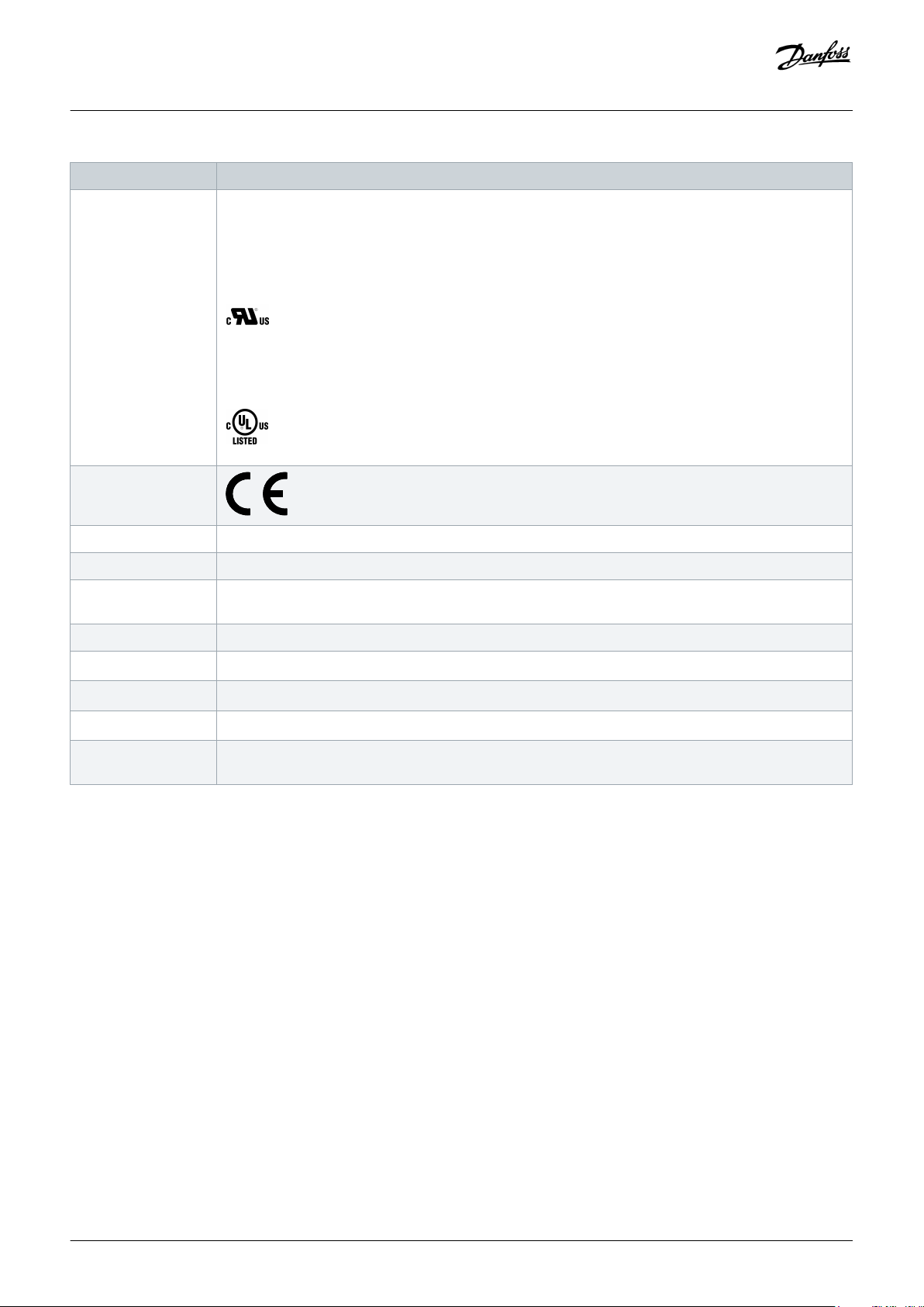
1.4 Approvals and Certifications
Table 2: Approvals and Certifications
Certification Description
IEC/EN 61800-3 Adjustable speed electrical power drive systems.
Part 3: EMC requirements and specific test methods.
IEC/EN 61800-5-1 Adjustable speed electrical power drive systems.
Part 5-1: Safety requirements - Electrical, thermal, and energy.
IEC/EN 61800-5-2 Adjustable speed electrical power drive systems.
Part 5-2: Safety requirements - Functional.
IEC/EN 61508-1 Functional safety of electrical/electronic/programmable electronic safety-related systems.
Part 1: General requirements.
IEC/EN 61508-2 Functional safety of electrical/electronic/programmable electronic safety-related systems.
Part 2: Requirements for electrical/electronic/programmable electronic safety-related systems.
Introduction
EN ISO 13849-1 Safety of machinery - Safety-related parts of control systems.
Part 1: General principles for design.
EN ISO 13849-2 Safety of machinery - Safety-related parts of control systems.
Part 2: Validation.
IEC/EN 60204-1 Safety of machinery - Electrical equipment of machines.
Part 1: General requirements.
IEC/EN 62061 Safety of machinery - Functional safety of safety-related electrical, electronic, and programmable electron-
ic control systems.
IEC/EN 61326-3-1 Electrical equipment for measurement, control, and laboratory use - EMC requirements.
Part 3-1: Immunity requirements for safety-related systems and for equipment intended to perform safetyrelated functions (functional safety) - General industrial applications.
IEC/EN 60529 Degrees of protection provided by enclosures (IP Code).
UL 508C UL Standard for Safety for Power Conversion Equipment.
(Only applies to ISD 510 servo drive sizes 1 and 2.)
Danfoss A/S © 2019.10
AQ262450196490en-000101 / 175R1170| 15
Page 16
Operating Guide | VLT® Multiaxis Servo Drive MSD 510 System
Certification Description
UL 61800-5-1 Adjustable speed electrical power drive systems.
Part 5-1: Safety requirements - Electrical, thermal, and energy.
ISD 510 servo drive sizes 3 and 4:
MSD 510:
CE
2014/30/EU Electromagnetic Compatibility (EMC) Directive.
Introduction
2014/35/EU Low Voltage Directive (LVD).
(2011/65/EU) amen-
Restriction of Hazardous Substances (RoHS).
ded (EU) 2015/863
2006/42/EC Machinery Directive (MD).
EtherCAT
®
Ethernet POWERLINK
PROFINET RT/IRT
PLCopen
®
®
Ethernet for Control Automation Technology. Ethernet-based fieldbus system.
®
Ethernet-based fieldbus system.
Ethernet-based fieldbus system.
Technical specification. Function blocks for motion control (formerly Part 1 and Part 2) Version 2.0 March
17, 2011.
1.5 Areas of Application
Potential areas of application are:
• Food and beverage machines
• Packaging machines
• Pharmaceutical machines
• Applications running with a group of servo drives
1.6 Software
Updates to the firmware, VLT® Servo Toolbox software, and PLC libraries may be available. When updates are available, they can be
downloaded from the danfoss.com website.
The VLT® Servo Toolbox software or the PLC libraries can be used to install the firmware on the servo drives or on the system modules.
16 | Danfoss A/S © 2019.10
AQ262450196490en-000101 / 175R1170
Page 17

Operating Guide | VLT® Multiaxis Servo Drive MSD 510 System
Introduction
1.7 Terminology
Table 3: Terminology
Term Description
ACM 510 Auxiliary Capacitors Module
DAM 510 Decentral Access Module that connects the Danfoss decentral servo drives (ISD 510 and DSD 510) to
the servo system via a hybrid cable.
DSD 510 Decentral Servo Drive
DSD 510 system compo-
Includes DSD 510 servo drives, PSM 510, DAM 510, and the optional ACM 510.
nents
EXM 510 Extension module
Feed-in cable Hybrid cable for connection from the DAM 510 to the 1st servo drive.
ISD 510 Integrated Servo Drive
ISD 510 system components Includes ISD 510 servo drives, PSM 510, DAM 510, and the optional ACM 510.
LCP Local Control Panel
Loop cable Hybrid cable for connecting servo drives in daisy-chain format.
MSD 510 Multiaxis Servo Drive
MSD 510 system compo-
Includes SDM 511/SDM 512, PSM 510, DAM 510, and the optional ACM 510.
nents
PLC Programmable Logic Controller (external device for controlling the servo system).
PSM 510 Power Supply Module that generates a 565–680 V DC supply.
SDM 511 Servo Drive Module (single axis)
SDM 512 Servo Drive Module (double axis)
System modules Includes PSM 510, DAM 510, and the optional ACM 510.
VIN PSM Input of PSM 510 (V AC).
V
PSM Output of PSM 510 (V DC).
OUT
Danfoss A/S © 2019.10
AQ262450196490en-000101 / 175R1170| 17
Page 18
Operating Guide | VLT® Multiaxis Servo Drive MSD 510 System
2 Safety
2.1 Safety Symbols
The following symbols are used in this guide:
WARNING
Indicates a potentially hazardous situation that could result in death or serious injury.
CAUTION
Indicates a potentially hazardous situation that could result in minor or moderate injury. It can also be used to alert against
unsafe practices.
NOTICE
Safety
Indicates important information, including situations that can result in damage to equipment or property.
2.2 Safety Instructions and Precautions
Compliance with the safety instructions and precautions is necessary at all times.
• Orderly and proper transport, storage, fitting, and installation, as well as careful operation and maintenance, are essential for the
trouble-free and safe operation of the servo system and its components.
• Only suitably trained and qualified personnel may work on the MSD 510 system and its components or in its vicinity.
• Only use accessories and spare parts approved by Danfoss.
• Comply with the specified ambient conditions.
• The information in this manual about the use of available components is provided solely by way of examples of applications and
suggestions.
• The plant engineer or system engineer is personally responsible for checking the suitability of the supplied components and the
information provided in this manual for the specific application concerned:
- For compliance with the safety regulations and standards relevant to the specific application.
- For implementing the necessary measures, changes, and extensions.
• Commissioning the servo system or its components is not allowed until it has been ascertained that the machine, system, or plant
in which they are installed conforms to the statutory provisions, safety regulations, and standards that apply to the application in
the country of use.
• Operation is only allowed in compliance with the national EMC regulations for the application concerned.
• Compliance with the limit values specified by national regulations is the responsibility of the producer of the plant, system, or
machine.
• Compliance with the specifications, connection conditions, and installation conditions in this manual is mandatory.
• The safety regulations and safety provisions of the country in which the equipment is used must be observed.
• To protect the user against electrical shock and to protect the servo system against overload, protective grounding is obligatory
and must be performed in accordance with local and national regulations.
18 | Danfoss A/S © 2019.10
AQ262450196490en-000101 / 175R1170
Page 19
Operating Guide | VLT® Multiaxis Servo Drive MSD 510 System
Safety
2.2.1 Operational Safety
Operational safety
• Safety-related applications are only allowed if they are explicitly and unambiguously mentioned in this manual.
• All applications that can cause hazards to people or damage to property are safety-related applications.
• The stop functions implemented in the software of the PLC do not interrupt the mains supply to the Power Supply Module
(PSM 510). Therefore, they must not be used for electrical safety for the servo system.
• The servo system can be brought to a stop by a software command or a zero speed setpoint, however DC voltage remains present
on the servo drives and/or mains voltage in the PSM 510. Also, when the system is stopped, it may start up again on its own if the
circuitry is defective or after the elimination of a temporary overload, a problem with the supply voltage, or a problem with the
system. If personal safety considerations (for example, risk of personal injury caused by contact with moving machine parts after an
unintended start) make it necessary to ensure that an unintended start cannot occur, these stop functions are not sufficient. In this
case, ensure that the servo system is detached from the mains network, and prevent unintended motor starting, for example by
using the Safe Torque Off function.
• The servo system may start running unintentionally during parameter configuration or programming. If this poses a risk to
personal safety (for example, risk of personal injury due to contact with moving machine parts), prevent unintended motor
starting, for example by using the Safe Torque Off function, or by safe disconnection of the servo drives.
• In addition to the L1, L2, and L3 supply voltage inputs on the PSM 510, the servo system has other supply voltage inputs, including
external auxiliary voltage. Before commencing repair work, check that all supply voltage inputs have been switched off and that
the necessary discharge time for the DC-link capacitors has elapsed.
2.3 Important Safety Warnings
The following safety instructions and precautions relate to the VLT® Multiaxis Servo Drive MSD 510 system. Read the safety instructions
carefully before starting to work in any way with the servo system or its components. Pay particular attention to the safety instructions
in the relevant sections of this manual.
WARNING
HAZARDOUS SITUATION
If the servo drive or the bus lines are incorrectly connected, there is a risk of death, serious injury, or damage to the unit.
Always comply with the instructions in this manual and national and local safety regulations.
-
WARNING
HIGH VOLTAGE
The MSD 510 system contains components that operate at high voltage when connected to the electrical supply network.
There are no indicators on the components that indicate the presence of mains supply. Incorrect installation, commissioning, or
maintenance may lead to death or serious injury.
Installation, commissioning, and maintenance may only be performed by qualified personnel.
-
WARNING
LEAKAGE/GROUNDING CURRENT HAZARD
Leakage/grounding currents are >3.5 mA. Improper grounding of the MSD 510 system modules may result in death or serious
injury.
For reasons of operator safety, use a certified electrical installer to ground the system correctly in accordance with the
-
applicable local and national electrical standards and directives, and the instructions in this manual.
Danfoss A/S © 2019.10
AQ262450196490en-000101 / 175R1170| 19
Page 20
Operating Guide | VLT® Multiaxis Servo Drive MSD 510 System
WARNING
DISCHARGE TIME
The MSD 510 system contains DC-link capacitors that remain charged for some time after the mains supply is switched off at
the Power Supply Module (PSM 510). Failure to wait the specified time after power has been removed before performing
service or repair work could result in death or serious injury.
To avoid electrical shock, fully disconnect the Power Supply Module (PSM 510) from the mains and wait for the capacitors
-
to fully discharge before carrying out any maintenance or repair work on the servo system or its components.
Minimum waiting time (minutes)
15
DANGER
Risque du choc électrique. Une tension dangereuse peut être présentée jusqu’à 15 min après avoir coupé l’alimentation.
-
Safety
WARNING
UNINTENDED START
The MSD 510 system contains servo drives, the PSM 510, and DAM 510 that are connected to the electrical supply network and
can start running at any time. This may be caused by a fieldbus command, a reference signal, or clearing a fault condition. Servo
drives and all connected devices must be in good operating condition. A deficient operating condition may lead to death,
serious injury, damage to equipment, or other material damage when the unit is connected to the electrical supply network.
Take suitable measures to prevent unintended starts.
-
WARNING
UNINTENDED MOVEMENT
Unintended movement may occur when parameter changes are carried out immediately, which may result in death, serious
injury, or damage to equipment.
When changing parameters, take suitable measures to ensure that unintended movement cannot pose any danger.
-
CAUTION
DANGER OF BURNS
The surface of the servo drives can reach high temperatures of over 90°C during operation.
Do not touch the servo drives until they have cooled down.
-
20 | Danfoss A/S © 2019.10
AQ262450196490en-000101 / 175R1170
Page 21

Operating Guide | VLT® Multiaxis Servo Drive MSD 510 System
Safety
NOTICE
RCD COMPATIBILITY
The MSD 510 system contains components that can cause a DC current in the protective earthing conductor, which may result
in malfunction in any devices connected to the system.
Where a residual current-operated protective (RCD) or monitoring (RCM) device is used for protection in case of direct or
-
indirect contact, use a type B RCD or RCM device on the supply side of the MSD 510 system components.
2.4 Qualified Personnel
Installation, commissioning, and maintenance may only be carried out by qualified personnel. For the purposes of this manual and the
safety instructions in this manual, qualified personnel are trained personnel who are authorized to fit, install, commission, ground, and
label equipment, systems, and circuits in accordance with the standards for safety technology and who are familiar with the safety
concepts of automation engineering.
Additionally, the personnel must be familiar with all the instructions and safety measures described in this manual.They must have
suitable safety equipment and be trained in first aid.
2.5 Due Diligence
The operator and/or fabricator must ensure that:
• The servo system and its components are used only as intended.
• The components are operated only in a perfect operational condition.
• The operating instructions are always available near the servo system in complete and readable form.
• The servo system and its components are fitted, installed, commissioned, and maintained only by adequately qualified and
authorized personnel.
• These personnel are regularly instructed on all relevant matters of occupational safety and environmental protection, as well as the
contents of the operating instructions and the instructions it contains.
• The product markings and identification markings applied to the components, as well as safety and warning instructions, are not
removed and are always kept in a legible condition.
• The national and international regulations regarding the control of machinery and equipment, that are applicable at the place of
use of the servo system, are complied with.
• The users always have all current information relevant to their interests about the servo system and its use and operation.
2.6 Intended Use
The components of the MSD 510 system are intended to be installed in machines used in industrial environments in accordance with
local laws and standards.
NOTICE
In a domestic environment, this product may cause radio interferences, in which case supplementary mitigation measures
-
may be required.
To ensure that the product is used as intended, the following conditions must be fulfilled before use:
Danfoss A/S © 2019.10
AQ262450196490en-000101 / 175R1170| 21
Page 22

Operating Guide | VLT® Multiaxis Servo Drive MSD 510 System
• Everyone who uses Danfoss products in any manner must read and understand the corresponding safety regulations and the
description of the intended use.
• Do not alter hardware from its original state.
• Do not reverse-engineer software products or alter their source code.
• Do not install or operate damaged or faulty products.
• Ensure that the products are installed in conformance with the regulations mentioned in the documentation.
• Observe any specified maintenance and service intervals.
• Comply with all protective measures.
• Only fit or install the components described in this operating guide. Third-party devices and equipment may be used only in
consultation with Danfoss.
2.6.1 Prohibited Application Areas
The servo system may not be used in the following application areas:
• Areas with potentially explosive atmospheres.
• Mobile or portable systems.
• Floating or airborne systems.
• Inhabited facilities.
• Sites where radioactive materials are present.
• Areas with extreme temperature variations or in which the maximum rated temperatures may be exceeded.
• Under water.
Safety
2.7 Forseeable Misuse
Any use not expressly approved by Danfoss constitutes misuse. This also applies to failure to comply with the specified operating
conditions and applications. Danfoss assumes no liability of any sort for damage attributable to improper use.
2.8 Service and Support
Contact the local service representative for service and support.
22 | Danfoss A/S © 2019.10
AQ262450196490en-000101 / 175R1170
Page 23
e30bg579.10
PSM
SDM 511
FS2
SDM 511
FS1
SDM 512
FS1
DAM 510
ACM 510
EXM 510
Operating Guide | VLT® Multiaxis Servo Drive MSD 510 System
System Description
3 System Description
3.1 Overview of the VLT® Multiaxis Servo Drive System MSD 510
The VLT® Multiaxis Servo Drive System MSD 510 is a high-performance central servo motion solution. The open system supports the
real-time Ethernet protocols EtherCAT®, Ethernet POWERLINK®, and PROFINET®.
Illustration 3: MSD Modules
The system comprises:
Danfoss A/S © 2019.10
AQ262450196490en-000101 / 175R1170| 23
Page 24

Operating Guide | VLT® Multiaxis Servo Drive MSD 510 System
• Power Supply Module (PSM 510)
• Drive Modules:
- Single axis Servo Drive Module (SDM 511)
- Double axis Servo Drive Module (SDM 512)
• Decentral Access Module (DAM 510)
• Auxiliary Capacitors Module (ACM 510)
• Expansion Module (EXM 510)
• Software:
- Firmware for the servo drive modules (SDM 511 and SDM 512)
- Firmware for the Power Supply Module (PSM 510)
- Firmware for the Decentral Access Module (DAM 510)
- Firmware for the Auxiliary Capacitors Module (ACM 510)
- VLT® Servo Toolbox
- PLC libraries for AutomationStudio™, TwinCAT®, SIMOTION Scout, and TIA Portal.
Some modules are available in 2 enclosure (frame) sizes with widths of 50 mm (FS1) or 100 mm (FS2) depending on the power size.
Depending on the application, the system can be used exclusively in a central system, or together with Danfoss Decentral Servo Drives
(ISD 510 and DSD 510) in a mixed system. Use of an AC choke is mandatory.
System Description
The system modules PSM 510, DAM 510, ACM 510, and drive modules SDM 511/SDM 512 are mounted to a backplate located in the
control cabinet. DC-link and the control voltage supply are integrated in the backplate. The 'click and lock' backplate concept offers
easy mounting and installation.
NOTICE
The MSD 510 modules cannot be used in servo systems from other manufacturers. Drives from other manufacturers cannot
-
be used in the MSD 510 system.
Contact Danfoss for further information.
-
NOTICE
The system modules have a protection rating of IP20 according to IEC/EN 60529 (except connectors, which are IP00). They
-
are only designed for use within a control cabinet. The system modules may be damaged if exposed to fluids.
3.1.1 Application Examples
There are numerous potential areas of application for the VLT® Multiaxis Servo Drive MSD 510 system as per the following examples.
Beverage machines
• Filling
• PET blow-moulding
Food and beverage packaging machines:
24 | Danfoss A/S © 2019.10
AQ262450196490en-000101 / 175R1170
Page 25

Operating Guide | VLT® Multiaxis Servo Drive MSD 510 System
• Flow wrapping
• Bag maker
• Tray sealing
• Shrink wrapping
Industrial and pharmaceutical packaging machines:
• Palletization
• Top loader
• Cartoning
• Tube filling
• Blister machine
• Liquid filling
• Solid dosing
3.1.2 Maximum Number of Modules
The maximum number of modules in the MSD 510 system is:
System Description
• PSM 510: 2 per system
• DAM 510: 3 per system (Depending on the system architecture it may be possible to add more. Contact Danfoss for further
information.)
• SDM 511/SDM 512: Depends on the current rating and output power of the servo drive modules and the AUX current consumption
during operation. Contact Danfoss for further information.
3.2 Power Supply Module PSM 510
3.2.1 Overview
PSM is the abbreviation for Power Supply Module. It is the power supply to the servo system. The PSM 510 supplies a DC power voltage
and guarantees high-density output. The DC-link and 24/48 V DC are distributed via the backlink in the backplates to all system
modules. The PSM 510 can be controlled via Ethernet-based fieldbus.
LEDs on the front of the PSM 510 show the operating status and warnings.
NOTICE
The MSD 510 system is designed for use within a control cabinet. If the STO function is used, the cabinet must be rated at
-
least IP54.
The PSM 510 has a protection rating of IP20 according to IEC/EN 60529 (except connectors, which are IP00).
-
The PSM 510 may be damaged if exposed to fluids.
-
All power cables are wired into the PSM 510, therefore at least 1 PSM 510 is required for each system.
The PSM 510 also performs service functions, such as voltage measuring, and is cooled by an internal fan.
The PSM 510 is available in 3 power sizes and delivers an output power of 10 kW, 20 kW, or 30 kW with 200% overload capacity for 3
seconds. Two PSM 510 modules can be used in parallel to achieve an output power of up to 60 kW.
Danfoss A/S © 2019.10
AQ262450196490en-000101 / 175R1170| 25
Page 26
2
1
3
4
5
6
7
8
9
e30bg581.11
Operating Guide | VLT® Multiaxis Servo Drive MSD 510 System
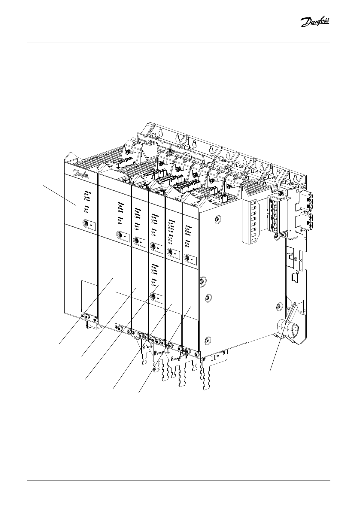
An example type code for the PSM 510 is: MSD510PSM510F2P10C0D6E20PLSXXXXXXXXXXXXX.
System Description
1 Backplate
3 Cable relief and shielding
5 Operating LEDs
7 PE screw
9 Internal/external brake resistor connector
Illustration 4: PSM 510
2 24/48 V input connector
4 Connectors: I/O, STO, relay, and Ethernet
6 LCP connector
8 AC mains supply connector
26 | Danfoss A/S © 2019.10
AQ262450196490en-000101 / 175R1170
Page 27
1 2
3
45
6
7
e30bg465.11
2
1
3
4
e30bg466.10
Operating Guide | VLT® Multiaxis Servo Drive MSD 510 System
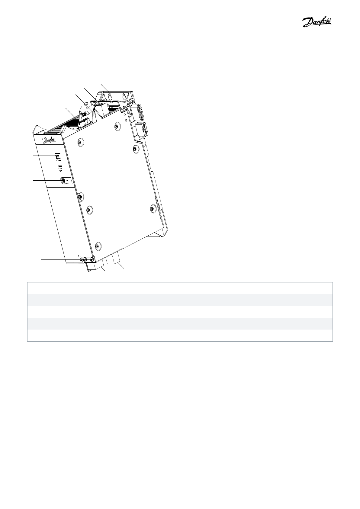
3.2.2 Connectors on the Top of PSM 510
System Description
1 Ethernet connector IN
3 24/48 V IN connector
5 STO connector OUT
7 Relay connector
Illustration 5: Connectors on the Top of PSM 510
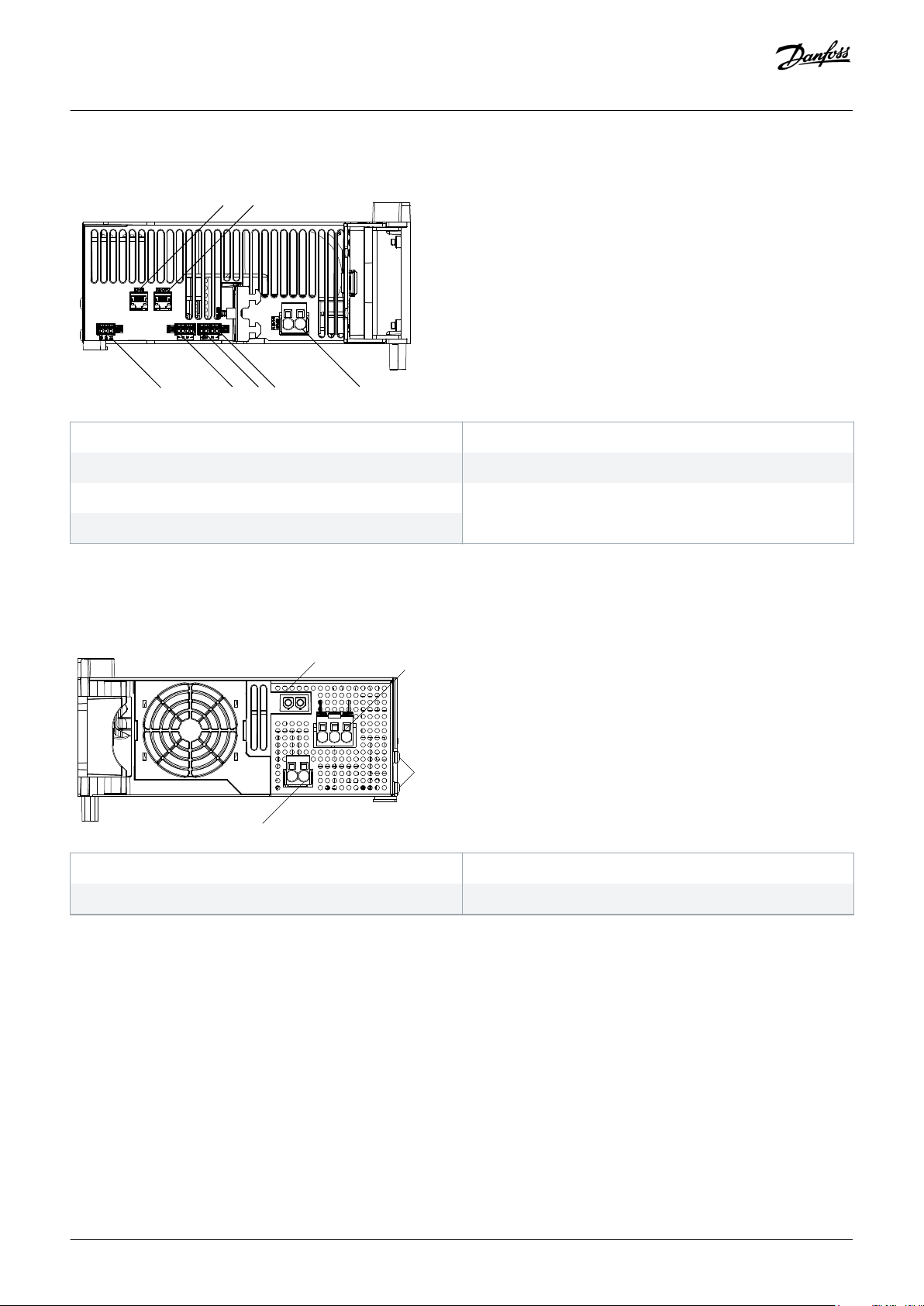
3.2.3 Connectors on the Bottom of PSM 510
1 Holder for internal brake resistor connector when not in use
2 Ethernet connector OUT
4 STO connector IN
6 I/O connector
2 AC mains supply connector
3 PE screws
Illustration 6: Connectors on the Bottom of PSM 510
4 Internal/external brake resistor connector
3.3 Servo Drive Module SDM 511/SDM 512
3.3.1 Overview
SDM is the abbreviation for Servo Drive Module. The SDM 511 is a single axis servo drive available in 5 power sizes and 2 enclosure
sizes (FS1 is 50 mm and FS2 is 100 mm). The SDM 512 is a double axis servo drive available in 3 power sizes and 1 enclosure size (FS1,
50 mm). A double axis module operates 2 servo motors independently. Several feedback options are available. The SDMs are equipped
with digital I/Os and Safe Torque Off (STO) and support several motor feedback encoders.
Danfoss A/S © 2019.10
AQ262450196490en-000101 / 175R1170| 27
Page 28
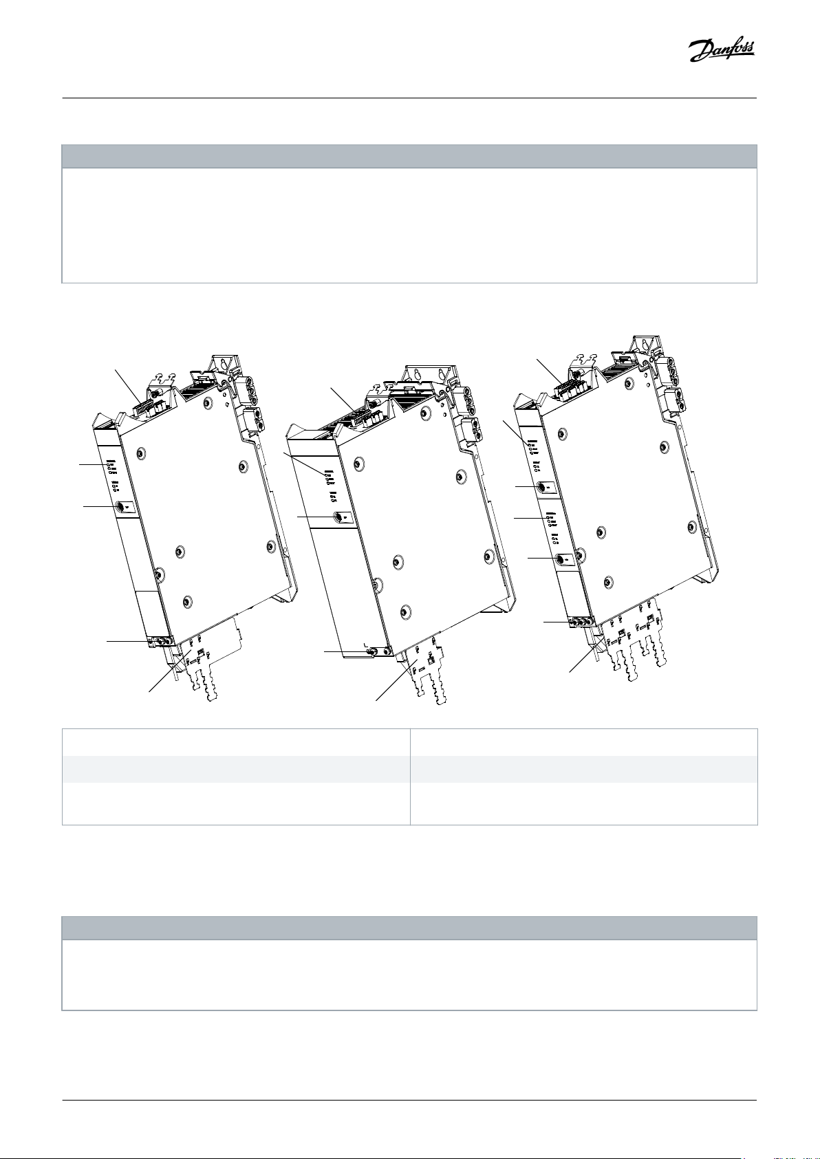
1
SDM 512 Frame Size 1
1
2
3
4
5
SDM 511 Frame Size 2
1
SDM 511 Frame Size 1
2
3
5
4
2
3
2
3
4
5
e30bg580.10
Operating Guide | VLT® Multiaxis Servo Drive MSD 510 System
NOTICE
The MSD 510 system is designed for use within a control cabinet. If the STO function is used, the cabinet must be rated at
-
least IP54.
The SDMs have a protection rating of IP20 according to IEC/EN 60529 (except connectors, which are IP00).
-
The SDMs may be damaged if exposed to fluids.
-
System Description
1 Connectors: I/O, STO, relay, Ethernet, and external encoder
3 LCP Connector
5 Connectors: Motor, motor feedback, thermistor, brake,
Illustration 7: SDM 511/SDM 512 Modules
3.3.2 SDM 511/SDM 512 Types
28 | Danfoss A/S © 2019.10
2 Operating LEDs
shielding, and cable relief
NOTICE
The Drive Configurator shows the valid configuration of servo drive variants. Only valid combinations are shown. Therefore,
-
not all variants detailed in the type code are visible.
4 PE screws
AQ262450196490en-000101 / 175R1170
Page 29
e30bg570.10
Operating Guide | VLT® Multiaxis Servo Drive MSD 510 System
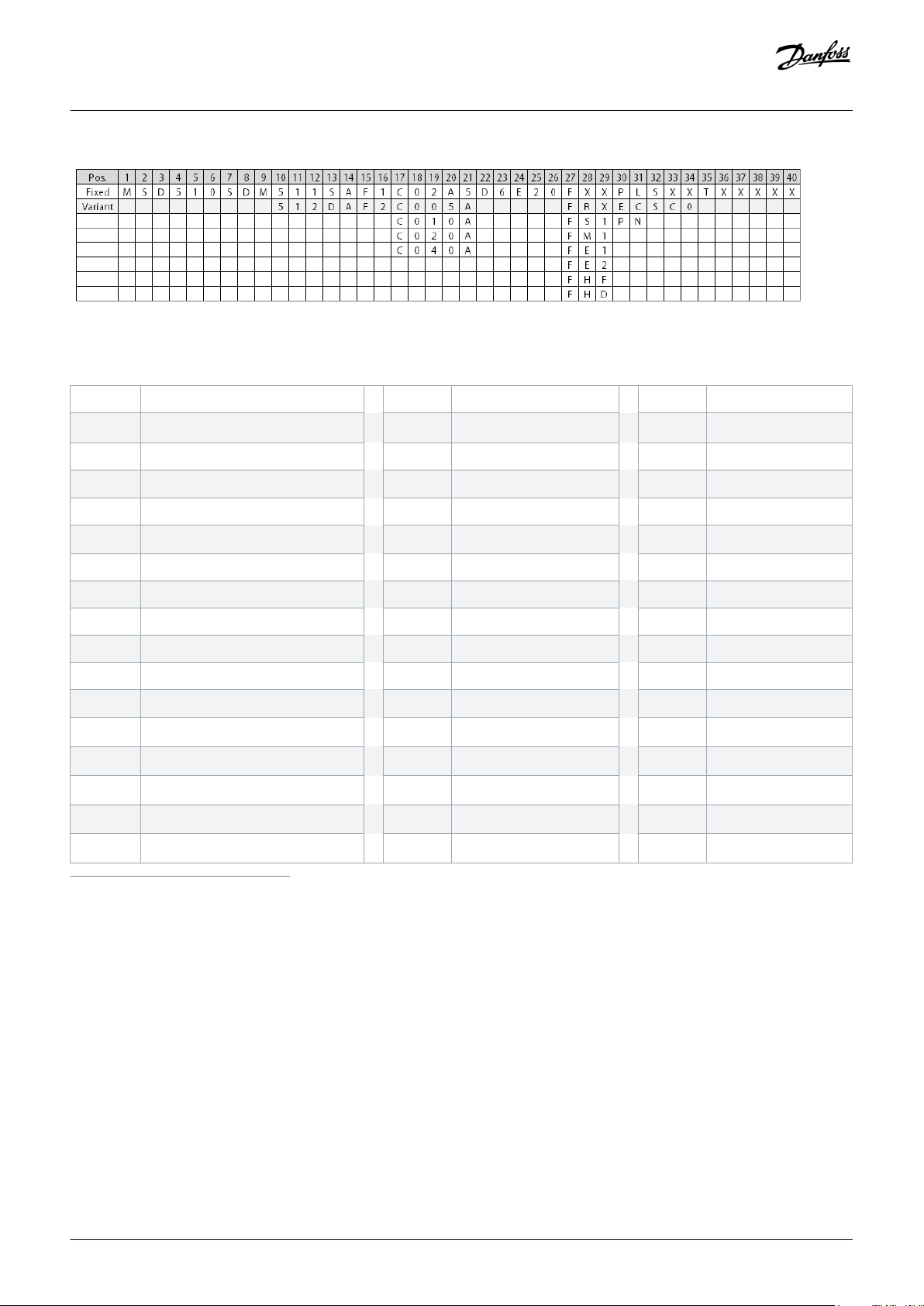
Illustration 8: Type Code
Table 4: Legend to Type Code
System Description
[01–06] Product group [22–23] DC voltage [32–34] Firmware
MSD510
VLT® Multiaxis Servo Drive
D6 600 V DC-link voltage SXX Standard
[07–12] Product variant [24–26] Drive enclosure SC0 Customized
SDM511 MSD 510 Servo Drive Module 511 E20
IP20
(1)
[35] Safety
SDM512 MSD 510 Servo Drive Module 512 [27–29] Bus system T Safe torque off (STO)
[13–14] Drive variant FXX
Without feedback
(2)
[36–40] Reserved
SA Single axis servo drive FRX Resolver XXXXX Reserved
DA Double axis servo drive FS1 BiSS ST feedback, 17 bit
[15–16] Enclosure (frame) size FM1 BiSS MT feedback, 17 bit
F1 Enclosure (frame) size 1, 50 mm FE1 EnDat 2.1
F2 Enclosure (frame) size 2, 100 mm FE2 EnDat 2.2
[17–21] Current rating FHF
C02A5 2.5 A
C005A 5 A
C010A 10 A
C020A 20 A
C040A 40 A
rms
rms
rms
rms
rms
FHD
[30–31] Bus system
PL POWERLINK
EC EtherCAT
PN PROFINET
HIPERFACE®
HIPERFACE® DSL
(2)
(2)
1
IP20 according to IEC/EN 60529 (except connectors, which are IP00)
2
In preparation
3.3.3 Components
3.3.3.1 Cooling
The Servo Drive Modules SDM 511 and SDM 512 are cooled by a speed-controlled internal fan.
3.3.4 Connectors on SDM 511
This section details all connectors on the SDM 511 in enclosure sizes 1 (FS1, 50 mm) and 2 (FS2, 100 mm).
Danfoss A/S © 2019.10
AQ262450196490en-000101 / 175R1170| 29
Page 30
1
243
657
e30bg443.10
1
2 3 4
6 5
7
e30bg444.10
1
3 2
e30bg446.10
Operating Guide | VLT® Multiaxis Servo Drive MSD 510 System
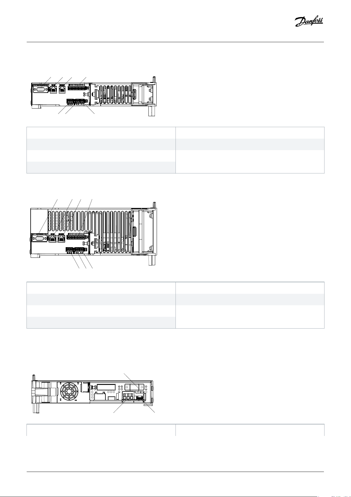
3.3.4.1 Connectors on the Top of SDM 511
System Description
1 External encoder connector
3 Ethernet connector OUT
5 STO connector IN
7 Relay connector
Illustration 9: SDM 511, Enclosure Size 1 (FS1)
1 External encoder connector
3 Ethernet connector OUT
2 Ethernet connector IN
4 I/O connector
6 STO connector OUT
2 Ethernet connector IN
4 I/O connector
5 STO connector IN
6 STO connector OUT
7 Relay connector
Illustration 10: SDM 511, Enclosure Size 2 (FS2)
3.3.4.2 Connectors on the Bottom of SDM 511
1 Motor feedback connector 2 Motor brake and thermistor connector
30 | Danfoss A/S © 2019.10
AQ262450196490en-000101 / 175R1170
Page 31
1
2
3
e30bg447.10
e30bg445.10
1 2 3 4 5
67
89
10
11
12
13
14
Operating Guide | VLT® Multiaxis Servo Drive MSD 510 System
3 Motor connector
Illustration 11: SDM 511, Enclosure Size 1 (FS1)
System Description
1 Motor feedback connector
2 Motor brake and thermistor connector
3 Motor connector
Illustration 12: SDM 511, Enclosure Size 2 (FS2)
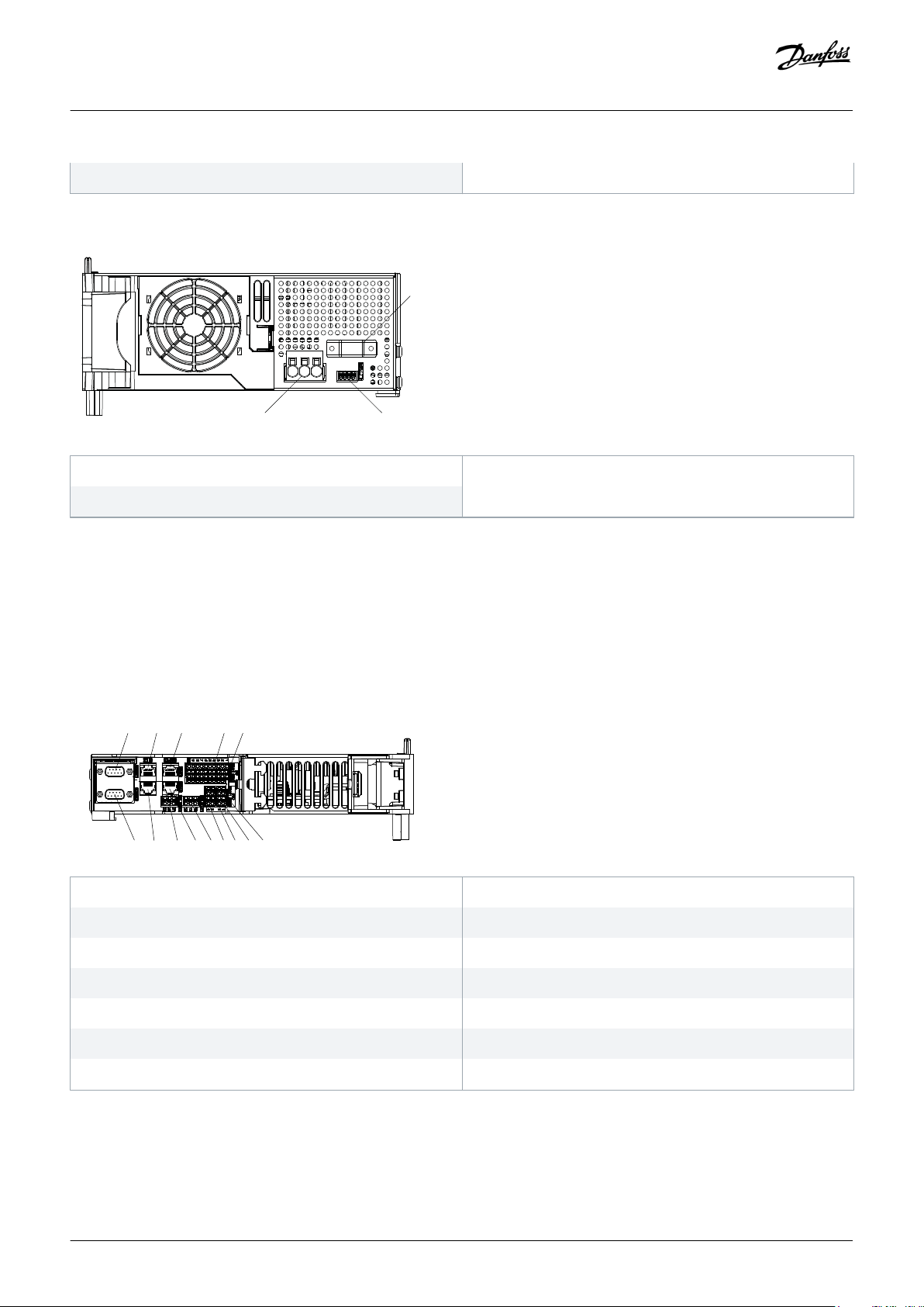
3.3.5 Connectors on SDM 512
This section details all connectors on SDM 512 in enclosure size 1 (FS1, 50 mm).
3.3.5.1 Connectors on the Top of SDM 512
1 External encoder connector SDM1
2 Ethernet connector IN SDM1
3 Ethernet connector OUT SDM1
5 I/O connector SDM2
7 STO connector IN SDM2
9 STO connector OUT SDM2
11 Ethernet connector OUT SDM2
13 Ethernet connector IN SDM2
Illustration 13: SDM 512, Enclosure Size 1 (FS1)
Danfoss A/S © 2019.10
4 I/O connector SDM1
6 STO connector IN SDM1
8 STO connector OUT SDM1
10 Relay connector SDM1
12 Relay connector SDM2
14 External encoder connector SDM2
AQ262450196490en-000101 / 175R1170| 31
Page 32

e30bg448.10
1 2
3456
Operating Guide | VLT® Multiaxis Servo Drive MSD 510 System
3.3.5.2 Connectors on the Bottom of SDM 512
System Description
1 Motor feedback connector SDM2
3 Motor brake and thermistor connector SDM1
5 Motor brake and thermistor connector SDM2
Illustration 14: SDM 512, Enclosure Size 1 (FS1)
2 Motor feedback connector SDM1
4 Motor connector SDM1
6 Motor connector SDM2
3.4 Decentral Access Module DAM 510
3.4.1 Overview
DAM is the abbreviation for Decentral Access Module. The DAM 510 is a central interface/gateway to the decentral servo system. It is
used to connect the Danfoss VLT® Integrated Servo Drives ISD 510 and VLT® Decentral Servo Drives DSD 510 to the servo system via a
hybrid feed-in cable.
The DAM 510 supplies the decentral servo drives with DC-link, U
The DAM 510 provides functions, such as:
• Overcurrent protection of the hybrid cable
• Overvoltage protection
• Charging circuit of the DC-link
• External encoder connection
• DC-link capacitance buffer for the decentral servo drives
, STO, and the Ethernet-based fieldbus via the hybrid feed-in cable.
AUX
The DAM 510 can be controlled via Ethernet-based fieldbus.
LEDs on the front of the DAM 510 show the operating status and warnings.
NOTICE
The MSD 510 system is designed for use within a control cabinet. If the STO function is used, the cabinet must be rated at
-
least IP54.
The DAM 510 has a protection rating of IP20 according to IEC/EN 60529 (except connectors, which are IP00).
-
The DAM 510 can be damaged if exposed to fluids.
-
An example type code for the DAM 510 is: MSD510DAM510F1C015AD6E20PLSXXXXXXXXXXXXX.
32 | Danfoss A/S © 2019.10
AQ262450196490en-000101 / 175R1170
Page 33

1
2
3
4
5
e30bg582.11
1 2
3
4
5
e30bg467.10
Operating Guide | VLT® Multiaxis Servo Drive MSD 510 System
System Description
1 Connectors: I/O, STO, relay, and Ethernet
3 LCP connector
2 Operating LEDs
4 PE screw
5 Connectors: UDC, AUX, STO out, and Ethernet
Illustration 15: DAM 510
3.4.2 Connectors on the Top of DAM 510
1 Ethernet connector IN
3 STO connector IN
2 Ethernet connector OUT
4 STO connector OUT
Danfoss A/S © 2019.10
AQ262450196490en-000101 / 175R1170| 33
Page 34

1
234
e30bg468.10
Operating Guide | VLT® Multiaxis Servo Drive MSD 510 System
5 External encoder connector
Illustration 16: Connectors on the Top of DAM 510
3.4.3 Connectors on the Bottom of DAM 510
System Description
1 Ethernet connector
3 STO out connector
Illustration 17: Connectors on the Bottom of DAM 510
2 AUX connector
4 UDC connector
3.5 Auxiliary Capacitors Module ACM 510
3.5.1 Overview
ACM is the abbreviation for Auxiliary Capacitors Module. The ACM 510 can be connected to the MSD 510 system to store energy,
enabling a controlled machine stop in emergency situations.
NOTICE
The MSD 510 system is designed for use within a control cabinet. If the STO function is used, the cabinet must be rated at
-
least IP54.
The ACM 510 has a protection rating of IP20 according to IEC/EN 60529 (except connectors, which are IP00).
-
The ACM 510 can be damaged if exposed to fluids.
-
An example type code for the ACM 510 is: MSD510ACM510F1E00C8D6E20PLSXXXXXXXXXXXXX.
34 | Danfoss A/S © 2019.10
AQ262450196490en-000101 / 175R1170
Page 35

1
2
3
4
e30bg583.10
CAP ST
NET ST
X1
X2
LCP
LINK/ACT
DEV
STATUS ACM
e30bg469.11
1
2
4 3
Operating Guide | VLT® Multiaxis Servo Drive MSD 510 System
System Description
1 Connectors: I/O, relay, and Ethernet
3 LCP connector
2 Operating LEDs
4 PE screw
Illustration 18: ACM 510
3.5.2 Connectors on the Top of ACM 510
1 Ethernet connector IN
3 I/O connector
Illustration 19: Connectors on the Top of ACM 510
2 Ethernet connector OUT
4 Relay connector
Danfoss A/S © 2019.10
AQ262450196490en-000101 / 175R1170| 35
Page 36

e30bh660.10
2
3
4
1
Operating Guide | VLT® Multiaxis Servo Drive MSD 510 System
3.6 Expansion Module EXM 510
System Description
1 EMC Shielding Plate
3 PE screw
Illustration 20: EXM 510
The MSD 510 system is designed for use within a control cabinet. If the STO function is used, the cabinet must be rated at
-
least IP54.
The EXM 510 has a protection rating of IP20 according to IEC/EN 60529 (except connectors, which are IP00).
-
The EXM 510 may be damaged if exposed to fluids.
-
2 Backplate
4 Expansion connector
NOTICE
An example type code for the EXM 510 is:
36 | Danfoss A/S © 2019.10
AQ262450196490en-000101 / 175R1170
Page 37

Operating Guide | VLT® Multiaxis Servo Drive MSD 510 System
MSD510EXM510F1C062AD6E20XXXXXXXXXXXXXXXX
System Description
3.7 Local Control Panel (LCP)
3.7.1 Overview of the Local Control Panel
The LCP is the graphical user interface for diagnostic and operating purposes. It is available as an option and can be connected to the
system modules using an optional cable (M8 to LCP SUB-D extension cable).
The LCP display provides the operator with a quick view of the state of the system modules, depending on which device it is connected
to. The display shows parameters and alarms/errors and can be used for commissioning and troubleshooting.
It can also be used to perform simple functions, for example activating and deactivating the output lines on the DAM 510 and opening
the mechanical brake on the SDM 511/512.
The LCP can be mounted on the front of the control cabinet using a mounting set (available as an accessory) and then connected to
the modules via M8 to SUB-D cables (available as an accessory). See the VLT® Servo Drive System ISD 510, DSD 510, MSD 510
Design Guide for accessory order numbers.
NOTICE
-
Further information on the LCP functions can be found in the VLT® Servo Drive System ISD 510, DSD 510, MSD 510
Programming Guide.
3.7.2 Layout of the Local Control Panel
The local control panel is divided into 4 functional groups:
• A: Display area
• B: Display menu keys
• C: Navigation keys and indicator lights (LEDs)
• D: Operation keys and reset
To adjust the display contrast, press [Status] and the [▵]/[▿] keys.
3.7.2.1 A: Display Area
The values in the display area differ depending on which module the LCP is connected to.
The display area is activated when the module it is connected to received power from U
AUX
.
Danfoss A/S © 2019.10
AQ262450196490en-000101 / 175R1170| 37
Page 38

Auto
On
Reset
Hand
On
Off
Main
Menu
Quick
Menu
Alarm
Log
Back
Cancel
Info
OK
2.1 kW
On
Alarm
Warn.
A
38 °C
11.5 A
24 V
B
C
D
565V
1
2
3
4
5
6
7
8
9
10
11
12
13
14
15
16
17
18 19
20
21
Status
e30bg799.10
Operating Guide | VLT® Multiaxis Servo Drive MSD 510 System
System Description
1 AUX line voltage
3 Actual UDC (current)
2 Temperature power card
4 Power consumption
5 Actual UDC (voltage)
Illustration 21: Display Area when Connected to the Power Supply Module PSM 510 or Decentral Access Module DAM 510
38 | Danfoss A/S © 2019.10
AQ262450196490en-000101 / 175R1170
Page 39

Auto
On
Reset
Hand
On
Off
Main
Menu
Quick
Menu
Alarm
Log
Back
Cancel
Info
OK
37 rpm
On
Alarm
Warn.
A
38 °C 750 deg0.10 A
B
C
D
1
2
3
4
6
7
8
9
10
11
12
13
14
15
16
17
18 19 20 21
Status
e30bh719.10
Velocity
Status
Enabled
Operating Guide | VLT® Multiaxis Servo Drive MSD 510 System
System Description
1 Current actual value
3 Position actual value
2 Temperature power card
4 Actual velocity
Illustration 22: Display Area when Connected to the Servo Drive Modules SDM 511/SDM 512
Danfoss A/S © 2019.10
AQ262450196490en-000101 / 175R1170| 39
Page 40

Auto
On
Reset
Hand
On
Off
Main
Menu
Quick
Menu
Alarm
Log
Back
Cancel
Info
OK
24 V
On
Alarm
Warn.
A
38 °C
40 °C
39 °C
B
C
D
565V
1
2
3
4
5
6
7
8
9
10
11
12
13
14
15
16
17
18 19
20
21
Status
e30bg798.10
Operating Guide | VLT® Multiaxis Servo Drive MSD 510 System
System Description
1 Temperature power card
3 Temperature capacitor bank 2
2 Temperature capacitor bank 1
4 AUX line voltage
5 Actual UDC (voltage)
Illustration 23: Display Area when Connected to the Auxiliary Capacitors Module ACM 510
3.7.2.2 B: Display menu keys
Menu keys are used for menu access for parameter set-up, toggling through status display modes during normal operation, and
viewing fault log data.
Table 5: Display Menu Keys
Key Function
6 Status Shows operational information.
7 Quick Menu Allows access to parameters.
8 Main Menu Allows access to parameters.
9 Alarm Log Shows the last 10 alarms.
40 | Danfoss A/S © 2019.10
AQ262450196490en-000101 / 175R1170
Page 41

Operating Guide | VLT® Multiaxis Servo Drive MSD 510 System
System Description
3.7.2.3 C: Navigation keys and indicator lights (LEDs)
Navigation keys are used for moving the display cursor and provide operation control in local operation. There are also 3 status LEDs in
this area.
Table 6: Navigation Keys
Key Function
10 Back Reverts to the previous step or list in the menu structure.
11 Cancel Cancels the last change or command as long as the display mode is not changed.
12 Info Press for a definition of the function being shown.
13 Navigation keys Use the 4 navigation keys to move between items in the menu.
14 OK Use to access parameter groups or to enable a selection.
Table 7: Indicator Lights (LEDs)
LED Color Function
15 On Green The On LED activates when the module it is connected to receives power from U
16 Warn Yellow When warning conditions are met, the yellow Warn LED activated and text appears in the display area
identifying the problem.
17 Alarm Red A fault condition causes the red Alarm LED to flash and an alarm text is shown.
AUX
..
3.7.2.4 D: Operation keys and reset
The operation keys are located at the bottom of the LCP.
Table 8: Operation Keys and Reset
Key Function
18 Hand On Enables the connected MSD 510 modules to be controlled via the LCP.
Switching between Hand On and Auto On modes is only possible in certain states (see the VLT® Servo Drive Sys‐
tem ISD 510, DSD 510, MSD 510 Programming Guide for further information).
19 Off Puts the servo drive module (SDM 511/512) into state Switch on Disabled and the other system modules into state
Standby.
This only works in Hand On mode.
Off mode enables transition from Hand On mode to Auto On mode.
20 Auto On Puts the system in remote operational mode.
In Auto On mode, the device is controlled by fieldbus (PLC). Switching between Auto On and Hand On modes is
only possible when the servo drive module is in state Switch on Disabled and/or the PSM 510, DAM 510 or
ACM 510 is in state Standby.
21 Reset Resets the MSD 510 system module after a fault has been cleared.
The reset is only possible when in Hand On mode.
Danfoss A/S © 2019.10
AQ262450196490en-000101 / 175R1170| 41
Page 42
Operating Guide | VLT® Multiaxis Servo Drive MSD 510 System
System Description
3.8 Cables
3.8.1 Hybrid Cable
Pre-configured hybrid cables are used to connect the decentral servo drives (when used) to the Decentral Access Module (DAM 510).
There are 2 types of hybrid cables that are available with both angled and straight M23 connectors:
• Feed-in cable for connecting the 1st ISD 510/DSD 510 servo drive of a group to the connection point on the Decentral Access
Module (DAM 510).
• Loop cable for connecting the ISD 510/DSD 510 servo drives in daisy-chain format in an application.
Both these cables are provided by Danfoss and are available in various lengths. See the VLT™ Servo Drive System ISD 510, DSD 510,
MSD 510 Design Guide for further information.
Both ends of the loop cable are fitted with M23 connectors.
The feed-in cable is fitted with an M23 connector at the output end for connection to the 1st ISD 510/DSD 510 servo drive. At the input
end it is pigtailed and the connectors are mounted on the corresponding terminals on the Decentral Access Module (DAM 510).
Table 9: Hybrid Cables
Cable type Shielded/unshielded Notes
Feed-in cable Shielded Hybrid cable (overall shield with additional fieldbus and safety section shield).
Loop cable
NOTICE
-
Hybrid cables are available in 2 cross-sections: 2.5 mm2 (15 A) and 4 mm2 (25 A). See the VLT® Servo Drive System ISD 510,
DSD 510, MSD 510 Design Guide for further information.
NOTICE
Minimum bending radius
The maximal number of bending cycles is 5 million at 7.5 x cable diameter (15.6 mm).
-
Permanently flexible: 12 x cable diameter.
-
Permanently installed: 5 x cable diameter.
-
3.8.2 Ethernet Cable
Table 10: Ethernet Cable Recommendations
Specification
Ethernet standard Standard Ethernet (in accordance with IEEE 802.3), 100Base-TX (Fast Ethernet)
Cable type S/FTP (shielded foiled twisted pair), ISO (IEC 11801 or EN 50173), CAT 5e or 6
42 | Danfoss A/S © 2019.10
AQ262450196490en-000101 / 175R1170
Page 43
Operating Guide | VLT® Multiaxis Servo Drive MSD 510 System
Specification
Damping 23.2 dB (at 100 Mhz and 100 m each)
Crosstalk damping 24 dB (at 100 Mhz and 100 m each)
Return loss 10 dB (100 m each)
Surge impedance 100 Ω
Maximum cable length 100 m between switches or network devices
System Description
NOTICE
Ground the Ethernet cable through the RJ45 connector. Do not ground it on the strain relief.
-
3.8.3 LCP Cable
The LCP cable is used to connect an LCP to a system module via the M8 connector on the front of each system module.
The LCP cable can be purchased from Danfoss (see the VLT® Servo Drive System ISD 510, DSD 510, MSD 510 Design Guide for further
information).
3.9 Cable Layout and Routing
The MSD 510 modules are connected via the backlink connector (see 11.7.1 Backlink Connector).
Connect the real-time Ethernet fieldbus to the 1st module in the MSD 510 system using a standard Ethernet cable (not provided).
Use the Ethernet loop cables provided by Danfoss to connect to the other modules in daisy-chain format.
3.9.1 Maximum Cable Lengths
Table 11: Maximum Cable Lengths
Cable type Specification Maximum Length
Hybrid cable M23 Feed-in 40 m
M23 Loop 25 m
Fieldbus extension Length: 2 m
Maximum length to next port: 100 m
Maximum cable length per line 100 m
Motor cable – Maximum length without additional output filter or choke: 30 m
Maximum length with additional output filter or choke: 80 m
Feedback cable – 80 m
Expansion module cable – 5 m
Danfoss A/S © 2019.10
AQ262450196490en-000101 / 175R1170| 43
Page 44

SDM 511/
SDM 512
Output filter
MCC
U
V
W
PE
U
V
W
3
M
PE
U1
V1
W1
PE
U2
V2
W2
PE
e30bh656.10
AC 400–480 V
. . .
ISD 510
DSD 510
. . .
Status
Hand
On
Off Reset
Auto
On
OK
Back
Cancel
Info
Quick
Menu
Main
Menu
Alarm
Log
LCP
PSM
510
DAM
510
DAM
510
STATUS PSM
LINK/ACT
DEV
STO
NET ST
X1
X2
STATUS DAM
LINK/ACT
DEV
STO
NET ST
AUX
X1
X2
X3
STATUS DAM
LINK/ACT
DEV
STO
NET ST
AUX
X1
X2
X3
PLC
1
2
e30bg794.10
UDC + Real-Time Ethernet Bus + STO + U
AUX
UDC + Real-Time Ethernet Bus + STO + U
AUX
3
24/48 V
STO
Operating Guide | VLT® Multiaxis Servo Drive MSD 510 System
System Description
3.9.2 Wiring of Output Filter
Illustration 24: Wiring Diagram of Output Filter
3.9.3 Standard Cabling Concept for 2 Decentral Access Modules (DAM 510)
In this example, a hybrid feed-in cable with quick-release connectors provides the supply voltage from the DAM 510 to the 1st ISD 510/
DSD 510 servo drive.
1 Hybrid feed-in cable
3 AC choke
2 Hybrid loop cable
Illustration 25: Standard Cabling Concept for 2 Decentral Access Modules (DAM 510)
3.10 Software
The software for the servo system comprises:
44 | Danfoss A/S © 2019.10
AQ262450196490en-000101 / 175R1170
Page 45

Operating Guide | VLT® Multiaxis Servo Drive MSD 510 System
• The firmware of the system modules that is already installed on the modules.
• A package of PLC libraries for Automation Studio™ for operating the MSD 510 devices (see 6.11.2 Creating an Automation Studio™
Project for further information).
• A PLC library for TwinCAT® 2 for operating the MSD 510 devices (see
• A PLC library for SIMOTION SCOUT for operating the MSD 510 devices (see 6.14.3 Creating a SIMOTION SCOUT® Project).
• A PLC library for TIA Portal for operating the MSD 510 devices.
• VLT® Servo Toolbox: A Danfoss PC-based software tool for commissioning and debugging the devices.
6.12.2 Creating a TwinCAT® Project for further information).
System Description
3.11 Fieldbus
The servo system has an open system architecture realized by fast Ethernet (100BASE-T) based communication. The system supports
EtherCAT®, Ethernet POWERLINK®, and PROFINET® fieldbuses. See the VLT™ Servo Drive System ISD 510, DSD 510, MSD 510,
Programming Guide for further information.
In productive environments, communication to the devices always takes place via a PLC that acts as a master. The ISD 510/DSD 510
servo drives, the servo drive modules SDM 511/SDM 512, and the system modules can be controlled by these communication
methods:
• Using the VLT® Servo Motion libraries (available for TwinCAT®, Automation Studio™ and SIMOTION SCOUT®, and TiA Portal).
• Using the NC axis functionality of TwinCAT® (ISD 510/DSD 510 and SDM 511/SDM 512 only).
• Using the CANopen® CiA DS 402 standard by reading and writing to objects.
• Using application class 1 (AC1), PROFINET® only.
The ISD 510/DSD 510 servo drives, the servo drive modules SDM 511/SDM 512,and the system modules can be operated with the
following cycle times.
• EtherCAT® and Ethernet POWERLINK® fieldbuses:
- 400 µs and multiples of it (for example, 800 µs and 1200 µs).
- 500 µs and multiples of it (for example, 1 ms).
• PROFINET® fieldbus
- 500 µs and multiples of it (for example, 1 ms).
When the cycle time is a multiple of 400 µs and 500 µs, the time base of 500 µs is used.
The ISD 510/DSD 510 servo drives, the servo drive modules SDM 511/SDM 512, and the system modules are certified for fieldbuses
according to the corresponding rules and regulations. The servo drives conform to the CANopen® CiA DS 402 Drive Profile.
3.11.1 EtherCAT®
The ISD 510/DSD 510 servo drives, servo drive modules SDM 511/SDM 512, and the system modules support the following EtherCAT
protocols:
• CANopen over EtherCAT® (CoE)
• File Access over EtherCAT® (FoE)
• Ethernet over EtherCAT® (EoE)
®
Danfoss A/S © 2019.10
AQ262450196490en-000101 / 175R1170| 45
Page 46
EtherCAT
Slave
Controller
(ESC)
OUT
LAN 1 (B)
OUT
2 (C)
IN
0
(A
)
X2
X
1
X3
e30be695.11
LAN
LAN
X1
X2
X3
ESC DAM
EtherCAT®
slave
OUT
LAN 2
IN
LAN 1
OUT
LAN 3
e30be696.11
Operating Guide | VLT® Multiaxis Servo Drive MSD 510 System
System Description
The ISD 510/DSD 510 servo drives, servo drive modules SDM 511/SDM 512, and the system modules support distributed clocks. To
compensate for the failure of a communication cable section in the system, cable redundancy is available for all fieldbuses. See the
VLT® Servo Drive System ISD 510, DSD 510, MSD 510 System Design Guide for further information.
X1 M23 hybrid cable connector to Decentral Access Module
X2 M23 hybrid cable connector to the next servo drive.
(DAM 510) or previous servo drive.
X3
M8 Ethernet cable connector to other EtherCAT® slaves, for
example EtherCAT® encoder.
The connector is only available on the advanced servo
drives.
Illustration 26: EtherCAT™ Port Assignment for the ISD 510/DSD 510 Servo Drive
X1 RJ45 cable connector to the previous slave.
X2 RJ45 to M23 hybrid feed-in cable to the 1st ISD 510/
DSD 510 servo drive.
X3 RJ45 cable connector to the PLC (cable redundancy) or next
slave.
Illustration 27: EtherCAT™ Port Assignment for the Decentral Access Module (DAM 510)
46 | Danfoss A/S © 2019.10
AQ262450196490en-000101 / 175R1170
Page 47

X1 X2
ESC
PSM/ACM/SDM
EtherCAT®
slave
IN
LAN 1
OUT
LAN 2
e30bg797.10
Operating Guide | VLT® Multiaxis Servo Drive MSD 510 System
System Description
X1 RJ45 cable connector to the PLC or previous slave. X2 RJ45 cable connector to the PLC (cable redundancy) or next
slave.
Illustration 28: EtherCAT™ Port Assignment for the Power Supply Module (PSM 510), Servo Drive Module SDM 511/SDM 512, and Auxiliary
Capacitors Module (ACM 510)
3.11.2 Ethernet POWERLINK®
The ISD 510/DSD 510 servo drives, servo drive modules SDM 511/SDM 512, and the system modules are certified according to DS 301
V1.1.0 and support the following features:
• Work as controlled node.
• Can be operated as multiplexed stations.
• Support of cross-communication.
• Ring redundancy is supported for media redundancy.
Specific ports are not assigned for Ethernet POWERLINK®.
3.11.3 PROFINET®
The ISD 510/DSD 510 servo drive, servo drive modules SDM 511/SDM 512, and system modules support PROFINET® conformance class
C as per IEC 61158-5-10:2014, IEC 61158-6-10:2014, IEC 61784-2:2014, and IEC 61784-5-3:2013. All the system components (servo drives
and system modules) act as I/O devices in a PROFINET® network.
The following features are supported:
• I/O-Device - Device that is being controlled by I/O-Controller
• Dynamic module configuration
• Net load class III
• Ring redundancy (MRPD) as client
PROFINET® fieldbus devices are always connected as network components via switches that are integrated in the fieldbus device. There
are 2 ports on the ISD 510/DSD 510 servo drives, servo drive modules SDM 511/SDM 512, the PSM 510, and the ACM 510). There are 3
ports on the DAM 510.
Danfoss A/S © 2019.10
AQ262450196490en-000101 / 175R1170| 47
Page 48

Operating Guide | VLT® Multiaxis Servo Drive MSD 510 System
4 Mechanical Installation
4.1 Items Supplied
Depending on the application, the items supplied for the MSD 510 system are:
• VLT® Power Supply Module (PSM 510)
• VLT® Single axis Servo Drive Module (SDM 511)
• VLT® Double axis Servo Drive Module (SDM 512)
• VLT® Decentral Access Module (DAM 510)
• VLT® Auxiliary Capacitors Module (ACM 510)
• VLT® Expansion Module (EXM 510)
• AC choke
• This operating guide
• Feed-in (hybrid) cable
• Loop (hybrid) cable
Mechanical Installation
NOTICE
The hybrid feed-in and loop cables are required when ISD510/DSD510 servo drives are used in the servo system.
-
The packaging unit depends on the number of modules delivered. Save the packaging for use in the event of product return.
4.2 Transport
• Always use means of transport and lifting gear with sufficient load capacity to transport the servo system components.
• Avoid vibration during transport.
• Avoid heavy impacts and blows.
4.3 Inspection on Receipt
Procedure
1. After receiving the delivery, immediately check whether the items supplied match the shipping documents. Danfoss does not
honor claims for faults registered later.
2. Register a complaint immediately with the carrier if there is visible transport damage.
3. Register a complaint immediately with the responsible Danfoss representative if there are visible defects or the delivery is
incomplete.
4.4 Safety Measures during Installation
Always observe the safety instructions in this manual during installation. Pay particular attention to ensuring that the following points
are always observed:
48 | Danfoss A/S © 2019.10
AQ262450196490en-000101 / 175R1170
Page 49

Operating Guide | VLT® Multiaxis Servo Drive MSD 510 System
• Installation may only be performed by qualified personnel.
• Installation must be performed with due care and attention.
• All safety regulations and protective measures must be complied with, and the environmental conditions must be observed.
• The manual is read and understood.
Mechanical Installation
4.5 Installation Environment
4.5.1 System Components
The environmental conditions for the MSD 510 system components are:
• The allowable operating ambient temperature range and vibration levels must not be exceeded (see 11.8 General Specifications
and Environmental Conditions for MSD 510 System).
• The allowable relative humidity range is 5–93%, non-condensing.
• The minimum space required above and below the system modules is detailed in 4.7.1 Space Requirements for System Modules.
4.6 Preparation for Installation
4.6.1 System Modules
Context:
Make the following preparations to ensure that the servo system can be installed reliably and effectively.
Always fit the system modules in accordance with local regulations.
Procedure
1. Provide a suitable mounting arrangement for the application. This depends on the type and weight of the modules.
2. To avoid misalignment, ensure that the backplates are perfectly level.
3. To ensure sufficient cooling, pay attention to the specified minimum space requirements.
4. Ground the modules.
Danfoss A/S © 2019.10
AQ262450196490en-000101 / 175R1170| 49
Page 50

(100 x number of FS2 + 50 x number of FS1) - 50
FS2 FS1
50 50
[1.97]
[0.42]
[14.45]
[1.97]
50 50
[1.97] [1.97]
M5
M5
367
UNF 10-32
UNF 10-32
Ø10,6
e30bg819.10
Operating Guide | VLT® Multiaxis Servo Drive MSD 510 System
4.6.2 Drilling Templates
Mechanical Installation
Illustration 29: Drilling templates for 50 mm and 100 mm System Modules
4.7 Installation Procedure
4.7.1 Space Requirements for System Modules
The modules can be mounted next to each other but require a minimum space at the top and bottom for cooling.
50 | Danfoss A/S © 2019.10
AQ262450196490en-000101 / 175R1170
Page 51

270
[10.63]
[3.94]
[3.3][15][6.1]
[0.24]
[14.4][0.28]
[1.18]
max. 100
min. 85
min. 30
[1.57]
min. 40
63677
max. 120
[4.72]
e30bg820.10
380min. 155
Operating Guide | VLT® Multiaxis Servo Drive MSD 510 System
Mechanical Installation
Illustration 30: Minimum Space Required at the Top and Bottom
Danfoss A/S © 2019.10
AQ262450196490en-000101 / 175R1170| 51
Page 52

60
[2.36]
60
[2.36]
101
[3.98]
106
[4.17]
e30bg821.10
Operating Guide | VLT® Multiaxis Servo Drive MSD 510 System
Mechanical Installation
Illustration 31: Minimum Space Required at the Sides
4.7.2 Installation Aids and Tools Required
For installation of the MSD 510 system modules, the tools corresponding to the fixings screws (not included) are required.
4.7.3 Fitting Instructions for System Modules
Context:
Mount the MSD 510system component with the highest output power next to the PSM 510. Mount the remaining system
-
components in descending order of output power.
NOTICE
52 | Danfoss A/S © 2019.10
AQ262450196490en-000101 / 175R1170
Page 53
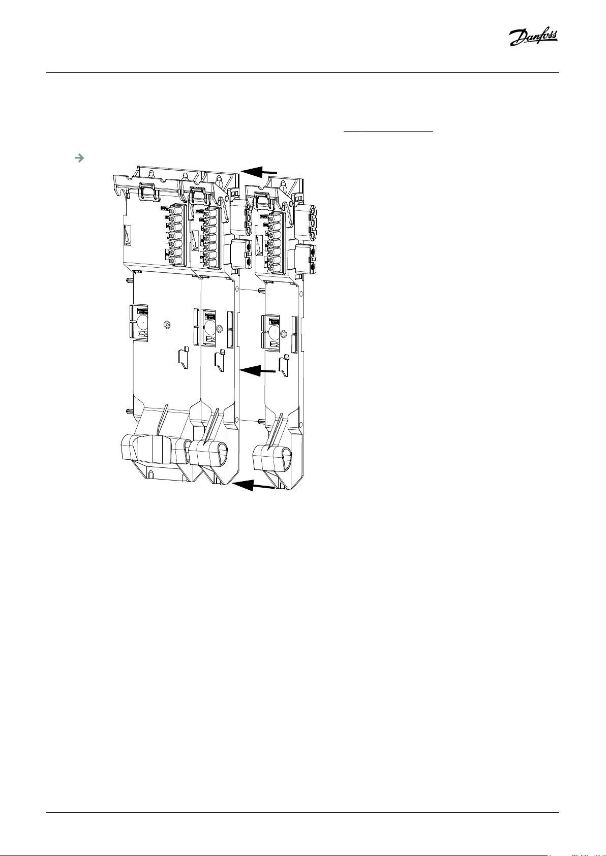
e30bg802.10
Operating Guide | VLT® Multiaxis Servo Drive MSD 510 System
Procedure
1. Drill the holes for mounting the backplate as per the drilling template (see 4.6.2 Drilling Templates).
2. Connect the backplates via the click and lock method.
Mechanical Installation
Illustration 32: Connecting the Backplates
3. Mount the backplates to the mounting plate in the control cabinet using M5 screws with a minimum head diameter or washer
diameter of 9.5 mm. The tightening torque is 3 Nm.
Danfoss A/S © 2019.10
AQ262450196490en-000101 / 175R1170| 53
Page 54

e30bg803.10
Operating Guide | VLT® Multiaxis Servo Drive MSD 510 System
Mechanical Installation
Illustration 33: Mounting the Backplates in the Control Cabinet
4. Slide the module onto the carrier at the bottom of the backplate.
5. Press the 1st module onto the backlink connector at the top of the backplate.
54 | Danfoss A/S © 2019.10
AQ262450196490en-000101 / 175R1170
Page 55

e30bg804.10
STATUS PSM
DEV
SVS ST
NET ST
LINK/ACT
X2
LCP
LCP
X1
STATUS DAM
DEV
SVS ST
NET ST
AUX
LINK/ACT
X1
X2
X3
X2
LIN
S
X
X3
1
e30bg815.10
STATUS PSM
DEV
SVS ST
NET ST
LINK/ACT
X1
X2
STATUS DAM
DEV
SVS ST
NET ST
AUX
LINK/ACT
X1
X2
X3
STATUS DAM
DEV
SVS ST
NET ST
AUX
LINK/ACT
X1
X2
X3
LCP
LCP
LCP
Operating Guide | VLT® Multiaxis Servo Drive MSD 510 System
Mechanical Installation
Illustration 34: Pressing the Module onto the Backlink Connector
6. To secure the module, pull down the holding clamp ([1] in illustration 35) at the top of the backplate.
Illustration 35: Pulling Down the Holding Clamp at the Top of the Backplate
7. Repeat steps 4, 5, and 6 for the remaining modules, ensuring that the lip at the left side of the 2nd module is inside the guiding
groove at the right side of the 1st module (([1] in illustration 36).
Danfoss A/S © 2019.10
AQ262450196490en-000101 / 175R1170| 55
Page 56

1
e30bg822.10
Operating Guide | VLT® Multiaxis Servo Drive MSD 510 System
Illustration 36: Guiding Groove
Mechanical Installation
56 | Danfoss A/S © 2019.10
AQ262450196490en-000101 / 175R1170
Page 57

Operating Guide | VLT® Multiaxis Servo Drive MSD 510 System
Electrical Installation
5 Electrical Installation
5.1 Warnings for Electrical Installation
During electrical installation, observe the relevant local and national regulations in addition to the information in this manual.
WARNING
LEAKAGE/GROUNDING CURRENT HAZARD
Leakage/grounding currents are >3.5 mA. Improper grounding of the MSD 510 system modules may result in death or serious
injury.
For reasons of operator safety, use a certified electrical installer to ground the system correctly in accordance with the
-
applicable local and national electrical standards and directives, and the instructions in this manual.
WARNING
HIGH VOLTAGE
The MSD 510 system contains components that operate at high voltage when connected to the electrical supply network.
There are no indicators on the components that indicate the presence of mains supply. Incorrect installation, commissioning, or
maintenance may lead to death or serious injury.
Installation, commissioning, and maintenance may only be performed by qualified personnel.
-
WARNING
HIGH VOLTAGE
Potentially lethal voltage is present on the connectors that may lead to death or serious injury.
Before working on the power connectors (disconnecting or connecting the cable), disconnect the PSM 510 from the mains
-
and wait for the discharge time to elapse.
5.2 Electrical Environmental Conditions
Compliance with the following electrical environmental conditions is necessary to enable safe and effective operation of the servo
system:
• Only for use in TN-S, TN-C, TN-CS, TT (not corner earthed) supply earthing system
• Prospective short-circuit current: 5 kA
• Protective class I
• Grounded 3-phase mains network, 400–480 V AC ±10%
• 3-phase frequency 44–66 Hz
• 3-phase lines and PE line
• External supply for auxiliary voltage, 24–48 V DC (PELV)
• AC choke (see 5.9.1 AC Line Choke)
• Observe the national statutory provisions.
• The leakage current is >3.5 mA.
Danfoss A/S © 2019.10
AQ262450196490en-000101 / 175R1170| 57
Page 58
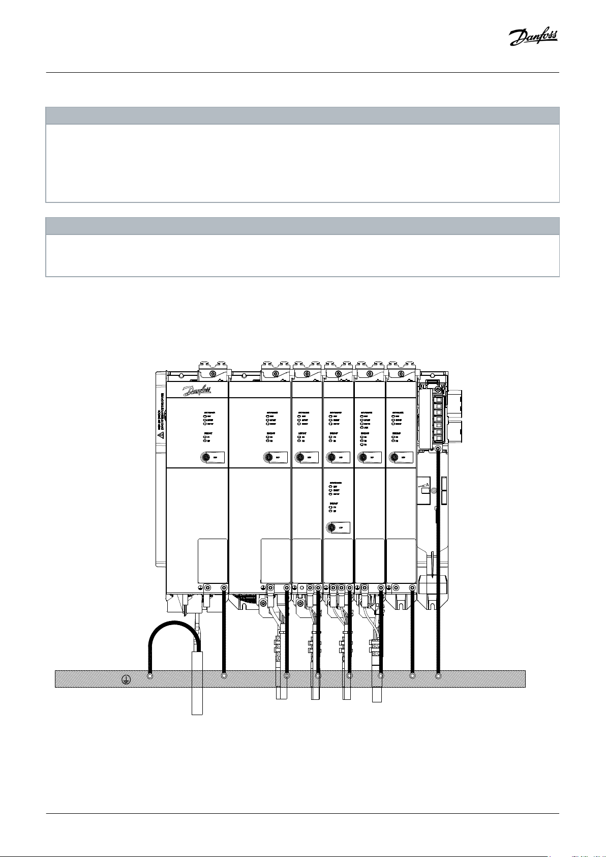
e30bh391.10
Operating Guide | VLT® Multiaxis Servo Drive MSD 510 System
Electrical Installation
NOTICE
RCD COMPATIBILITY
The MSD 510 system contains components that can cause a DC current in the protective earthing conductor, which may result
in malfunction in any devices connected to the system.
Where a residual current-operated protective (RCD) or monitoring (RCM) device is used for protection in case of direct or
-
indirect contact, use a type B RCD or RCM device on the supply side of the MSD 510 system components.
NOTICE
All modules must be mounted in a control cabinet.
-
5.3 Grounding
5.3.1 Grounding for Electrical Safety
Illustration 37: Grounding for Electrical Safety
58 | Danfoss A/S © 2019.10
AQ262450196490en-000101 / 175R1170
Page 59

Operating Guide | VLT® Multiaxis Servo Drive MSD 510 System
• Ground the ISD 510/DSD 510 servo drives with the PE wire of the feed-in cable. There is a dedicated PE screw on the front and
another on the back of the DSD 510 servo drive.
• Ensure that the machine frame has a proper electrical connection to the flange of the servo drive. Use the front side flange surface.
Ensure PE connection on that part of the machine.
• To comply with CE requirements, ensure a minimum ground wire cross-section of at least 16 mm2 (minimum 70 °C, Cu).
To comply with UL requirements, ensure a minimum ground wire cross-section of at least 6 AWG (minimum 60 °C, Cu).
If a PSM 510 module with 10 kW is used, the cable cross-section can be reduced to:
- 10 mm2 (minimum 70 °C, Cu) to comply with CE requirements
- 8 AWG (minimum 60 °C, Cu) to comply with UL requirements
• Do not ground the MSD 510 system components in daisy-chain format. Use the grounding method depicted in
• Keep the ground wire connections as short as possible.
• Follow the wiring requirements in this manual.
Electrical Installation
illustration 37.
Danfoss A/S © 2019.10
AQ262450196490en-000101 / 175R1170| 59
Page 60

1
2
3
e30bg805.10
1
2
3
e30bh343.10
Operating Guide | VLT® Multiaxis Servo Drive MSD 510 System
Electrical Installation
5.3.2 Grounding for EMC-Compliant Installation
• Establish electrical contact between the cable shield and the enclosure using the I/O shielding plate on each module.
1 Cable
3 I/O shielding plate
Illustration 38: Cable Shielding on the Top of the System Components
1 Cable tie
3 PE screw
2 Cable tie
2 EMC metal shielding plate
Illustration 39: Cable Shielding on the Bottom of the System Components
• Use a cable with a shielding that has a high-coverage to reduce electrical interference.
• Do not use pigtails to connect the shielding. A 360° wire connection is recommended.
60 | Danfoss A/S © 2019.10
AQ262450196490en-000101 / 175R1170
Page 61

Operating Guide | VLT® Multiaxis Servo Drive MSD 510 System
Electrical Installation
NOTICE
POTENTIAL EQUALIZATION
There is a risk of electrical interference when the ground potential between the servo system and the machine is different.
-
Install equalizing cables between them. The recommended cable cross-section is 16 mm2.
NOTICE
EMC INTERFERENCE
Use shielded cables for control wiring and separate cables for power and control wiring. Failure to isolate power and
-
control wiring can result in unintended behavior or reduced performance.
Ensure a minimum clearance of 200 mm between signal and power cables.
-
Only cross cables at 90°.
-
5.4 Mains Supply Requirements
Ensure that the supply has the following properties:
• TN-S, TN-C, TN-CS, TT (not corner earthed) supply earthing system.
• Prospective short-circuit current: 5 kA.
• Protective class I.
• Grounded 3-phase mains network, 400–480 V AC ±10%.
• 3-phase lines and PE line.
• 3-phase frequency: 44–66 Hz
• Maximum input current for 1 PSM 510 at 30 kW: 55 A
rms
5.4.1 Fuses
NOTICE
Use fuses on the supply side of the Power Supply Module PSM 510 that comply with CE and UL requirements (see table 12).
-
When 2 PSM 510 modules are used, each PSM 510 must have its own dedicated set of fuses.
-
Table 12: Fuses
Model and power rating CE Compliance (IEC 60364) UL Compliance (NEC 2014)
Maximum fuse type Maximum fuse type
PSM 510 (10 kW) gG 25 A 30 A (class T or J only)
PSM 510 (20 kW) gG 50 A 50 A (class T or J only)
PSM 510 (30 kW) gG 63 A 80 A (class T or J only)
Danfoss A/S © 2019.10
AQ262450196490en-000101 / 175R1170| 61
Page 62

Operating Guide | VLT® Multiaxis Servo Drive MSD 510 System
Electrical Installation
5.4.2 Circuit Breakers
Use a type B or type C circuit breaker with a capacity of 1.5 times the rated current of PSM 510 to fulfill CE requirements.
NOTICE
Circuit breakers are not allowed in installations where C-UL is required. Only UL recommended fuses are allowed.
-
5.5 Auxiliary Supply Requirements
Supply the PSM 510 with a power supply unit with an output of 24/48 V DC ±10% (PELV) and maximum 50 A (the actual current
depends on the modules used). The output required depends on the system topology. The output ripple of the power supply unit
must be <250 mVpp.
Refer to the VLT® Servo Drive System ISD 510, DSD 510, MSD 510 Design Guide for power rating shell diagrams.
NOTICE
Only use supply units that conform to the PELV specification.
-
Use a supply that is CE-marked according to the standards EN 61000-6-2 and EN 61000-6-4 or similar for industrial use.
-
The secondary circuit must be supplied from an external isolated source.
-
The 24/48 V DC external supply for auxiliary voltage must be dedicated to the MSD 510 system, meaning that the supply is used
exclusively for powering the PSM 510. The maximum cable length between the supply and the PSM 510 is 3 m.
5.5.1 Fuses
UL listed fuses are recommended to protect the wiring on 24–48 V DC.
Table 13: Fuses
CE Compliance (IEC 60364) UL Compliance (NEC 2014)
Maximum fuse type Maximum fuse type
(1)
50 A
1
If the maximum current is lower, a fuse with lower current rating can be used. Rating of IEC fuses: according to 100% of maximum current. Use a time delay fuse rated according to
the DC voltage used.
2
If the maximum current is lower, a fuse with lower current rating can be used. Rating of UL fuses: according to 125% of maximum current. Use a time delay fuse rated according to
the DC voltage used.
63 A
(2)
5.6 Safety Supply Requirements
Supply the STO line with a 24 V DC supply for industrial use with the following properties:
62 | Danfoss A/S © 2019.10
AQ262450196490en-000101 / 175R1170
Page 63

Operating Guide | VLT® Multiaxis Servo Drive MSD 510 System
• Output range: 24 V DC ±10%
• Maximum current: 1 A
Use a 24 V supply unit that is CE marked for industrial use. Ensure that the supply fulfills the PELV specification and is only used for the
system safety input.
A common supply for auxiliary and safety supply can be used, provided the only connection point of the 2 circuits is near to the supply.
This is intended to avoid interference due to a common voltage drop. The maximum cable length between the 24 V supply unit and
the servo system is 3 m.
The safety supply can be looped from PSM 510 to the other MSD 510 system components except for ACM 510, which does not have an
STO connection. The cable for this is not provided. For further information, see 8.6 Installation.
Electrical Installation
NOTICE
Ensure reinforced isolation between safety signals and other signals, supplies (mains supply), and exposed conductive
-
parts.
5.7 UL Requirements
NOTICE
Integral solid-state short-circuit protection does not provide branch circuit protection. Branch circuit protection must be
-
provided in accordance with the National Electrical Code/Canadian Electrical Code, and any additional local codes or
equivalent.
Suitable for use on a circuit capable of delivering not more than 5000 rms symmetrical amperes, 480 V maximum when
-
protected by maximum 80 A class J or T fuses.
To meet the UL (Underwriters Laboratories) regulations, use a UL-approved copper cable with a minimum heat-resistance
-
of 60 °C. Use Class 1 wire only. For PSM 510 rated 30 kW, use a maximum heat resistance of 75 °C.
Control Circuit Overcurrent Protection is required.
-
Danfoss A/S © 2019.10
AQ262450196490en-000101 / 175R1170| 63
Page 64

1
2
3
4
5
e30bg808.10
40
Axis 2:170
Axis 1:120
10
60
12
40
60
15
15
150
1
2
3
4
5
e30bh465.10
Operating Guide | VLT® Multiaxis Servo Drive MSD 510 System
5.8 Connecting the Servo Drive Module SDM 511/SDM 512
5.8.1 Connecting the Motor Cable
Context:
Electrical Installation
1 Shielded area
3 V
2 U
4 W
5 PE
Illustration 40: Motor Cable for 50 mm Wide Servo Drive Modules
1 Shielded area 2 U
64 | Danfoss A/S © 2019.10
AQ262450196490en-000101 / 175R1170
Page 65

1
2
e30bg809.10
1
2
e30bg810.10
Operating Guide | VLT® Multiaxis Servo Drive MSD 510 System
Electrical Installation
3 V
4 W
5 PE
Illustration 41: Motor Cable for 100 mm Wide Servo Drive Modules
Illustration 42: Connecting the Motor Cable on 50 mm Wide Servo Drive Modules
Illustration 43: Connecting the Motor Cable on 100 mm Wide Servo Drive Modules
Procedure
1. Insert the wires into the motor connector.
2. Insert the motor connector [1].
3. Secure and shield the motor cable using the cable tie [2].
Danfoss A/S © 2019.10
AQ262450196490en-000101 / 175R1170| 65
Page 66

1
55
8
2
3
4
e30bg811.10
1
3
2
4
5
e30bg812.10
Operating Guide | VLT® Multiaxis Servo Drive MSD 510 System
5.8.2 Connecting the Brake/Thermistor Cable
Context:
Electrical Installation
1 Motor temperature –
3 Motor brake –
Illustration 44: Brake/Thermistor Cable
1 Motor PE screw
3 Cable tie for brake/thermistor cable
2 Motor temperature +
4 Motor brake +
2 Brake/thermistor connector
4 EMC plate
5 EMC plate screw
Illustration 45: Connecting the Brake/Thermistor Cable
NOTICE
Use a motor with reinforced insulation between the thermistor and the motor windings (tested with 4300 V DC and
-
8000 V
66 | Danfoss A/S © 2019.10
impulse).
peak
AQ262450196490en-000101 / 175R1170
Page 67

1
2 3 4
6 5
7
e30bg444.10
Operating Guide | VLT® Multiaxis Servo Drive MSD 510 System
Electrical Installation
Procedure
1. Insert the wires into the brake/thermistor connector.
2. Plug the brake/thermistor connector [2] into the servo drive module SDM 511/SDM 512.
3. Secure the brake/thermistor cable using the cable tie [3].
4. Tighten the EMC plate screw [5]. The tightening torque is 3 Nm.
5. Plug the motor feedback connector (SUB-D, 26 pin) into the servo drive module.
6. Connect the servo drive module SDM 511/SDM 512 to PE by connecting a PE wire to the PE screw on the front side of the module
[1]. The tightening torque is 3 Nm.
5.8.3 Connecting the Cables on the Top of the Servo Drive Modules SDM 511/SDM 512
Context:
1 External encoder connector (E SDM 511/512)
3 Ethernet connector OUT (X2 OUT)
5 STO connector IN (STO SDM 511/512)
2 Ethernet connector IN (X1 IN)
4 I/O connector (I/O SDM 511/512)
6 STO connector OUT (STO SDM 511/512)
7 Relay connector (REL SDM 511/512)
Illustration 46: Connectors on the Top of SDM 511/SDM 512 (Example)
Procedure
1. Connect the Ethernet cable from the output of the previous module to the input connector [2].
2. Insert the wires from the STO output of the previous module into the 24 V IN (STO input) connector.
3. Insert the 24 V IN (STO input) connector [5] into the SDM 511/SDM 512.
4. If required, insert the external encoder connector [1].
5. If I/Os are required, insert the wires into the I/O connector and insert the connector [4].
6. If a relay is required, insert the wires into the relay connector and insert the connector [7].
Danfoss A/S © 2019.10
AQ262450196490en-000101 / 175R1170| 67
Page 68

Operating Guide | VLT® Multiaxis Servo Drive MSD 510 System
Electrical Installation
5.9 Connecting the Power Supply Module PSM 510
5.9.1 AC Line Choke
It is mandatory to use a 3-phase AC line choke (see 5.9.1.1 Connecting 1 PSM 510 to the AC Choke and 5.9.1.2 Connecting 2 PSM 510
Modules to the AC Choke).
Table 14: Line Choke Characteristics for 1 PSM 510
Model Minimum I
[A] U
rms
[V] Inductance [mH]
rms
PSM 510 (10 kW) 20 500 Minimum: 0.47
Maximum: 1.47
PSM 510 (20 kW) 40 500 Minimum: 0.47
Maximum: 1.47
PSM 510 (30 kW) 60 500 0.47 ±10%
If 2 PSM 510 modules are installed in parallel, use an AC choke as specified in table 15. See 5.9.1.2 Connecting 2 PSM 510 Modules to
the AC Choke for further information.
Table 15: Line Choke Characteristics for 2 PSM 510 installed in parallel
Model Minimum I
[A] U
rms
[V] Inductance [mH]
rms
PSM 510 (2 x 30 kW) 125 500 0.24 ±10%
Danfoss recommends mounting the AC line choke close to the PSM 510.
The maximum cable length depends on the cross-section, and the required voltage and current at the DC-link.
If the AC line chokes are mounted away from the PSM 510, the maximum cable distance is 5 m.
5.9.1.1 Connecting 1 PSM 510 to the AC Choke
Connect the PSM 510 to the electric grid with the correct AC choke for the power size of the PSM 510.
68 | Danfoss A/S © 2019.10
AQ262450196490en-000101 / 175R1170
Page 69
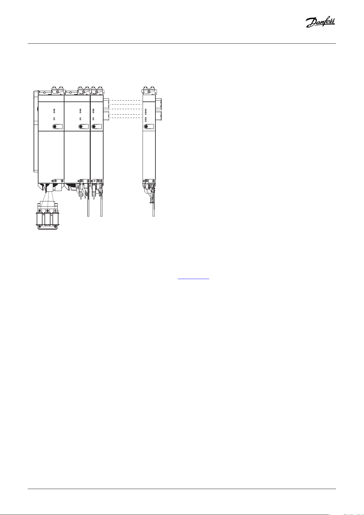
STATUS PSM
DEV
STO
NET ST
LINK/ACT
X1
X2
LCP LCP LCP
STATUS SDM
DEV
STO
NET ST
LINK/ACT
X1
X2
STATUS SDM
DEV
STO
NET ST
LINK/ACT
X1
X2
LCP
STATUS DAM
DEV
STO
NET ST
AUX
LINK/ACT
X1
X2
X3
e30bh420.10
PSM 510
SDM 511
SDM 511/
SDM 512
DAM 510
Operating Guide | VLT® Multiaxis Servo Drive MSD 510 System
Electrical Installation
Illustration 47: Connecting 1 PSM 510 to the AC Choke
5.9.1.2 Connecting 2 PSM 510 Modules to the AC Choke
Connect the PSM 510 modules to the same AC choke as shown in illustration 48.
Ensure the choke used is the correct size based on the combined power of the PSM 510 modules.
When 2 PSM 510 modules are used, the wiring between the AC line choke and each PSM 510 must be the same length within a
tolerance of 0.5 m.
Connect each PSM 510 to the AC choke directly. Parallel wiring is not permitted.
Danfoss A/S © 2019.10
AQ262450196490en-000101 / 175R1170| 69
Page 70

STATUS PSM
DEV
SVS ST
NET ST
LINK/ACT
X1
X2
LCP
STATUS PSM
DEV
SVS ST
NET ST
LINK/ACT
X1
X2
LCP
LCP LCP
STATUS SDM
DEV
SVS ST
NET ST
LINK/ACT
X1
X2
STATUS SDM
DEV
SVS ST
NET ST
LINK/ACT
X1
X2
LCP
STATUS DAM
DEV
SVS ST
NET ST
AUX
LINK/ACT
X1
X2
X3
PSM 510
PSM 510
SDM 511
SDM 511/
SDM512
DAM 510
e30bh421.11
... ...
STATUS PSM
DEV
SVS ST
NET ST
LINK/ACT
X1
X2
LCP LCP LCP LCP LCP LCP LCP LCP
STATUS PSM
DEV
SVS ST
NET ST
LINK/ACT
X1
X2
STATUS SDM
DEV
SVS ST
NET ST
LINK/ACT
X1
X2
STATUS SDM
DEV
SVS ST
NET ST
LINK/ACT
X1
X2
e30bh422.10
STATUS DAM
DEV
SVS ST
NET ST
AUX
LINK/ACT
X1
X2
X3
STATUS ACM
DEV
CAP ST
NET ST
LINK/ACT
X1
X2
STATUS SDM
DEV
SVS ST
NET ST
LINK/ACT
X1
X2
STATUS SDM
DEV
SVS ST
NET ST
LINK/ACT
X1
X2
PSM 510
PSM 510
SDM 511
SDM 511/
SDM512
SDM 511
SDM 511/
SDM512
ACM 510
DAM 510
EXM 510
...
Operating Guide | VLT® Multiaxis Servo Drive MSD 510 System
Electrical Installation
Illustration 48: Connecting 2 PSM 510 Modules to the AC Choke
5.9.1.3 Connecting 2 PSM 510 Modules to the AC Choke with System Splitting
Connect the PSM 510 modules to the same AC choke regardless of the load position (for example, before or after the system splitting)
as shown in illustration 49.
Ensure the choke used is the correct size based on the combined power of the PSM 510 modules.
When 2 PSM 510 modules are used, the wiring between the AC line choke and each PSM 510 must be the same length within a
tolerance of 0.5 m.
Connect each PSM 510 to the AC choke directly. Parallel wiring is not permitted.
Illustration 49: Connecting 2 PSM 510 Modules to the AC Choke with System Splitting
70 | Danfoss A/S © 2019.10
AQ262450196490en-000101 / 175R1170
Page 71

1 2
3
45
6
7
e30bg465.11
Operating Guide | VLT® Multiaxis Servo Drive MSD 510 System
Electrical Installation
If 2 AC chokes are used (1 per PSM 510) and both PSM 510 modules are mounted at the same side of the system splitting, the setup is
permitted with derating equal to the AC choke's tolerance referred to 60 kW. For example, 10% derating is 54 kW.
If 2 AC chokes are used (1 per PSM 510) where 1 PSM 510 module is mounted before and 1 after the splitting, the loads must be
balanced equally. Otherwise, the derating of both PSM 510 modules is equal to the AC choke's tolerance. For example, tolerance 10%
+ 10% means –20% derating.
If 2 AC chokes are used (1 per PSM 510) and 1 PSM 510 module is mounted before the splitting and 1 after the splitting and half of the
loads are set before the system splitting and half are set after the system splitting, the setup is permitted with derating equal to the AC
choke's tolerance referred to 60 kW. For example, 10% derating is 54 kW.
NOTICE
Further information on the EXM 510 module and wiring can be found in 11.7.15 Expansion Module Connector.
-
5.9.2 Connecting the Cables on the Power Supply Module PSM 510
5.9.2.1 Connecting the Cables on the Top of the Power Supply Module PSM 510
Context:
1 Ethernet connector IN (X1 IN)
3 24/48 V IN connector (INPUT 24/48 V)
5 STO connector OUT (STO PSM)
7 Relay connector (REL PSM)
Illustration 50: Connectors on the Top of PSM 510
2 Ethernet connector OUT (X2 OUT)
4 STO connector IN (STO PSM)
6 I/O connector (I/O PSM)
Danfoss A/S © 2019.10
AQ262450196490en-000101 / 175R1170| 71
Page 72

2
1
3
4
e30bg466.10
Operating Guide | VLT® Multiaxis Servo Drive MSD 510 System
Procedure
1. Connect the Ethernet cable from the PLC to the Ethernet input connector [1].
2. Connect the Ethernet cable from the Ethernet output connector [2] to the next module.
3. Insert the wires into the 24/48 V IN connector.
4. Insert the 24/48 V IN connector [3].
5. Insert the wires into the STO connector IN connector.
6. Insert the STO connector IN (STO PSM) connector [4].
7. Insert the wires into the STO connector OUT connector.
8. Insert the STO connector OUT (STO PSM) connector [5].
9. If I/Os are required, insert the wires into the I/O connector and insert the connector (I/O PSM) [6].
10. If a relay is required, insert the wires into the relay connector and insert the connector (REL PSM) [7].
5.9.2.2 Connecting the Cables on the Bottom of the Power Supply Module PSM 510
Context:
Electrical Installation
1 Holder for internal brake resistor connector when not in use
3 PE screws
Illustration 51: Connectors on the Bottom of PSM 510
2 AC mains supply connector
4 Internal/external brake resistor connector
Procedure
1. Insert the wires into the AC mains supply connector.
2. Insert the AC mains supply connector [2].
3. If an external brake resistor is required:
A Unplug the internal brake resistor connector [4] and insert the external brake connector in its place.
B Plug the internal brake resistor connector to the internal brake connector holder [1].
4. Connect the PSM 510 to the PE screw on the front side [3] using a PE wire. The tightening torque is 3 Nm.
72 | Danfoss A/S © 2019.10
AQ262450196490en-000101 / 175R1170
Page 73

1 2
3
4
5
e30bg467.10
1
234
e30bg468.10
Operating Guide | VLT® Multiaxis Servo Drive MSD 510 System
5.10 Connecting the Decentral Access Module (DAM 510)
5.10.1 Connecting the Cables on the Top of the Decentral Access Module DAM 510
Context:
Electrical Installation
1 Ethernet connector IN (X1 IN)
3 STO connector IN (STO DAM)
2 Ethernet connector OUT (X3 OUT)
4 STO connector OUT (STO DAM)
5 External encoder connector (E DAM)
Illustration 52: Connectors on the Top of DAM 510
Procedure
1. Connect the Ethernet cable from the output of the previous module to the input connector [1].
2. Insert the wires from the STO output of the previous module into the 24 V IN (STO input) connector, see
on the Top of DAM 510.
3. Insert the 24 V IN (STO connector IN) connector [3] into the DAM 510.
4. If required, connect the external encoder connector [5].
5.10.2 Connecting the Feed-In Cable
Context:
11.7.10.3.1 STO Connectors
1 Ethernet connector
3 STO out connector
Illustration 53: Connectors on the Bottom of DAM 510
Danfoss A/S © 2019.10
2 AUX connector
4 UDC connector
AQ262450196490en-000101 / 175R1170| 73
Page 74
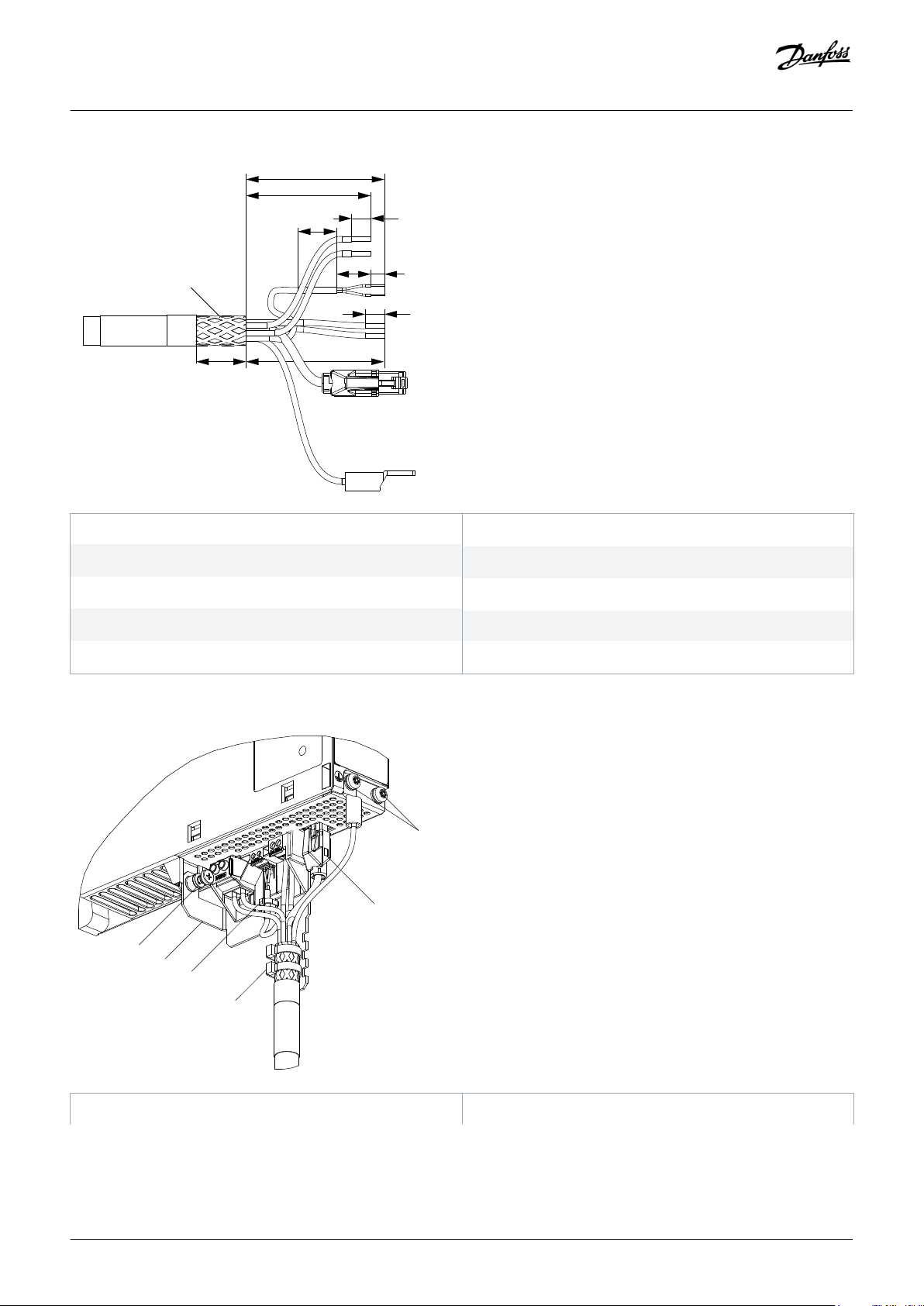
1
26
117
80
10
20
87
18
10
7
2
3
4
5
6
7
8
9
e30bg806.10
1
2
3
4
5
6
e30bg807.10
Operating Guide | VLT® Multiaxis Servo Drive MSD 510 System
Electrical Installation
1 Shielded area
3
UDC– (gray, 2.5 mm2/4 mm2)
5
STO– (gray, 0.5 mm2)
7
AUX– (blue, 2.5 mm2)
9
PE (yellow/green, 2.5 mm2/4 mm2, fork lug)
Illustration 54: Feed-In Cable
2
UDC+ (black, 2.5 mm2/4 mm2)
4
STO+ (pink, 0.5 mm2)
6
AUX+ (red, 2.5 mm2)
8 Ethernet/fieldbus (green, RJ45 connector)
1 Feed-in cable PE screws 2 Bus connector
74 | Danfoss A/S © 2019.10
AQ262450196490en-000101 / 175R1170
Page 75
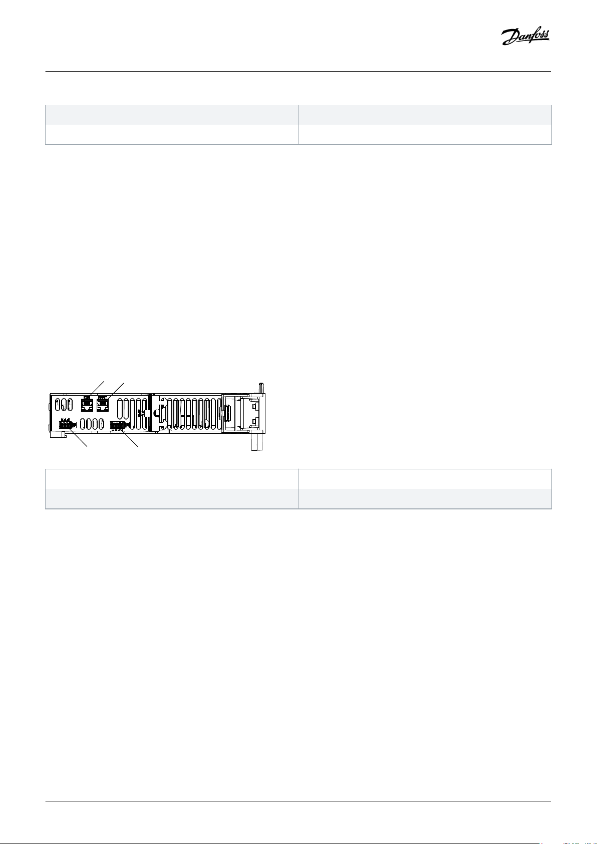
e30bh350
.11
1
2
4 3
Operating Guide | VLT® Multiaxis Servo Drive MSD 510 System
Electrical Installation
3 Cable tie for feed-in cable
5 EMC plate
Illustration 55: Connecting the Feed-In Cable
4 Cable tie for STO cable
6 EMC plate screw
Procedure
1. Insert the wires into the UDC, AUX, and STO connectors.
2. Secure the feed-in cable using the cable ties [3], ensuring that the shielded area is positioned exactly under the cable tie.
3. Secure the STO cable using the cable tie [4], ensuring that the shielded area is positioned exactly under the cable tie.
4. Insert the connectors on the feed-in cable into their corresponding terminal block on the DAM 510.
5. Tighten the screw on the EMC plate [6]. The tightening torque is 3 Nm.
6. Insert the RJ45 bus connector [2].
7. Connect the DAM 510 to the PE screw on the front side [1] using a PE wire. The tightening torque is 3 Nm.
5.11 Connecting the Auxiliary Capacitors Module ACM 510
Context:
1 Ethernet connector IN (X1 IN)
3 I/O connector (I/O ACM)
Illustration 56: Connectors on the Top of ACM 510
2 Ethernet connector OUT (X2 OUT)
4 Relay connector (REL ACM)
Procedure
1. Connect the Ethernet cable from the output of the previous system module to the input connector (X1 IN) [1].
2. If I/Os are required, insert the wires into the I/O connector (I/O ACM) and insert the connector [3].
3. If a relay is required, insert the wires into the relay connector (REL ACM) and insert the connector [4].
4. Connect the ACM 510 to the PE screw on the front side using a PE wire. The tightening torque is 3 Nm.
Danfoss A/S © 2019.10
AQ262450196490en-000101 / 175R1170| 75
Page 76

12
5315
8
1
2
3
4
5
6
7
e30bh661.10
e30bh392.11
1
2
3
4
5
6
7
Operating Guide | VLT® Multiaxis Servo Drive MSD 510 System
5.12 Connecting the Expansion Module EXM 510
Context:
Electrical Installation
1 24/48 V
3 Functional earth
5 DC–
7 DC+
Illustration 57: Expansion Module Cable
2 GND
4 DC–
6 DC+
8 Shielded area
1 EMC shielding plate screw
3 DC cables
5 GND cable
7 Cable tie
Illustration 58: Connecting the Expansion Module EXM 510
76 | Danfoss A/S © 2019.10
2 PE screw
4 Functional earth cable
6 24/48 V cable
AQ262450196490en-000101 / 175R1170
Page 77

Operating Guide | VLT® Multiaxis Servo Drive MSD 510 System
Electrical Installation
NOTICE
If 2 separate backlinks are used (connected via 1 or 2 pairs of EXM 510 modules), the 2 grounding bars must be also
-
connected together with a 16 mm2 (6 AWG) cable cross-section.
Procedure
1. Insert wires [3], [4], [5], and [6] into the expansion connector.
2. Secure the DC cables [3] using the cable tie [7], ensuring that the shielded area is positioned exactly under the cable tie.
3. Secure the cables [4], [5], and [6] using the cable ties [7].
4. Plug the connectors into the backplate.
5. Tighten the screw on the EMC shielding plate [1]. The tightening torque is 3 Nm.
6. Ground the expansion module to PE using a PE wire and the PE screw [2]. The tightening torque is 3 Nm.
5.13 Connecting the Brake Resistor on the PSM 510
The PSM 510 is connected to the internal brake resistor as shown in illustration 59.
Alternatively, the PSM 510 can be connected to an external brake resistor. In this case, the internal brake resistor on the PSM 510 must
remain unconnected and the connector can be placed in the internal brake resistor connector holder (see 3.2.3 Connectors on the
Bottom of PSM 510).
Paralleling or series of brake resistors is not permitted.
Danfoss A/S © 2019.10
AQ262450196490en-000101 / 175R1170| 77
Page 78
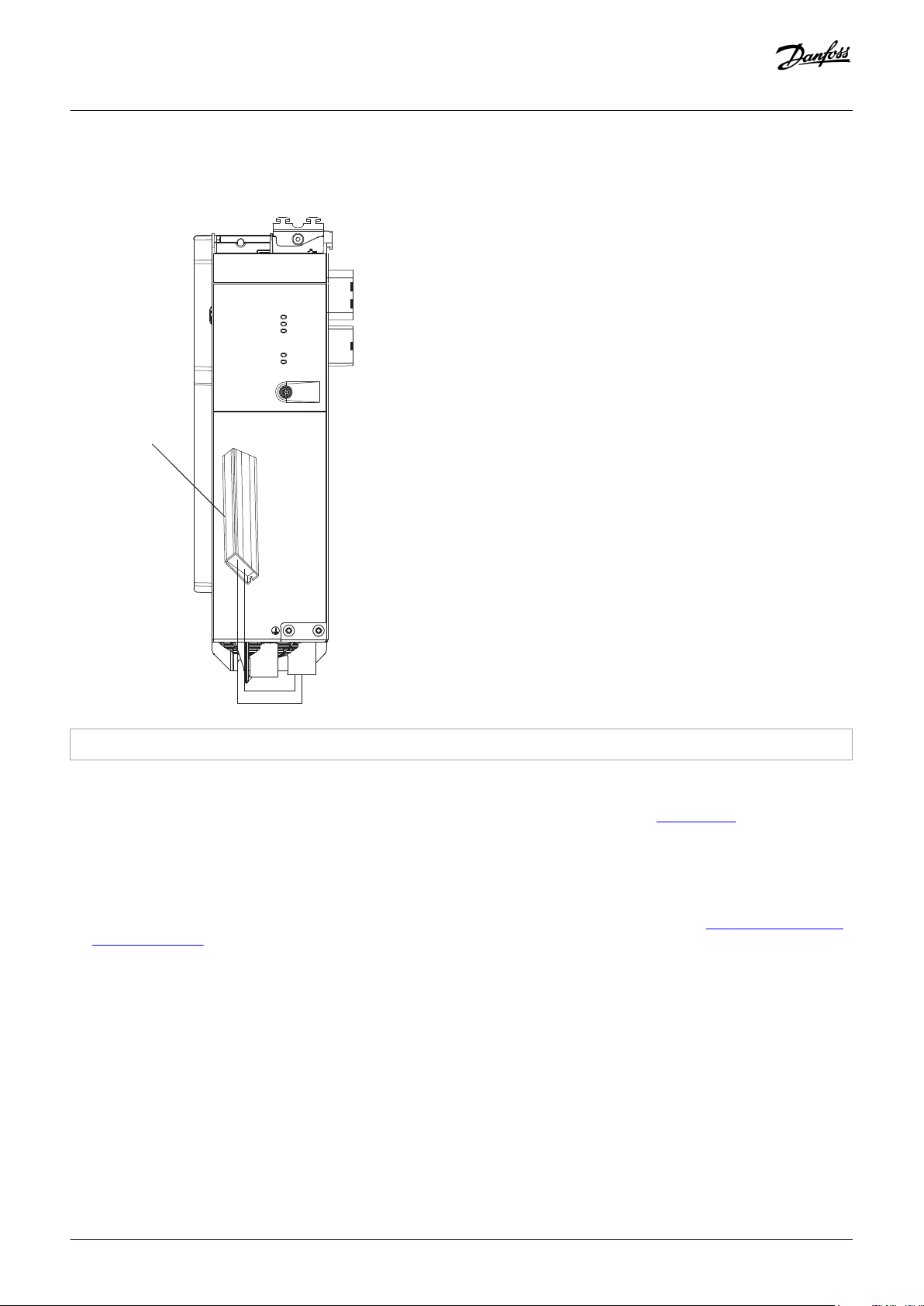
STATUS PSM
DEV
SVS ST
NET ST
LINK/ACT
X1
X2
LCP
1
e30bh423.10
PSM 510
Operating Guide | VLT® Multiaxis Servo Drive MSD 510 System
Electrical Installation
1 Internal brake resistor
Illustration 59: Connection of Internal Brake Resistor on 1 PSM 510
When using 2 PSM 510 modules, connect each PSM 510 to its own internal brake resistor as shown in
illustration 60 (factory setting).
Alternative permitted configurations for 2 PSM 510 modules:
• 1 PSM 510 is connected to the internal brake resistor and the other is connected to an external brake resistor.
• Both PSM 510 modules are connected to an external brake resistor. In this case, the internal brake resistor on the PSM 510 must
remain unconnected and the connector can be placed in the internal brake resistor connector holder (see
Bottom of PSM 510).
Paralleling or series of brake resistors is not permitted.
3.2.3 Connectors on the
78 | Danfoss A/S © 2019.10
AQ262450196490en-000101 / 175R1170
Page 79
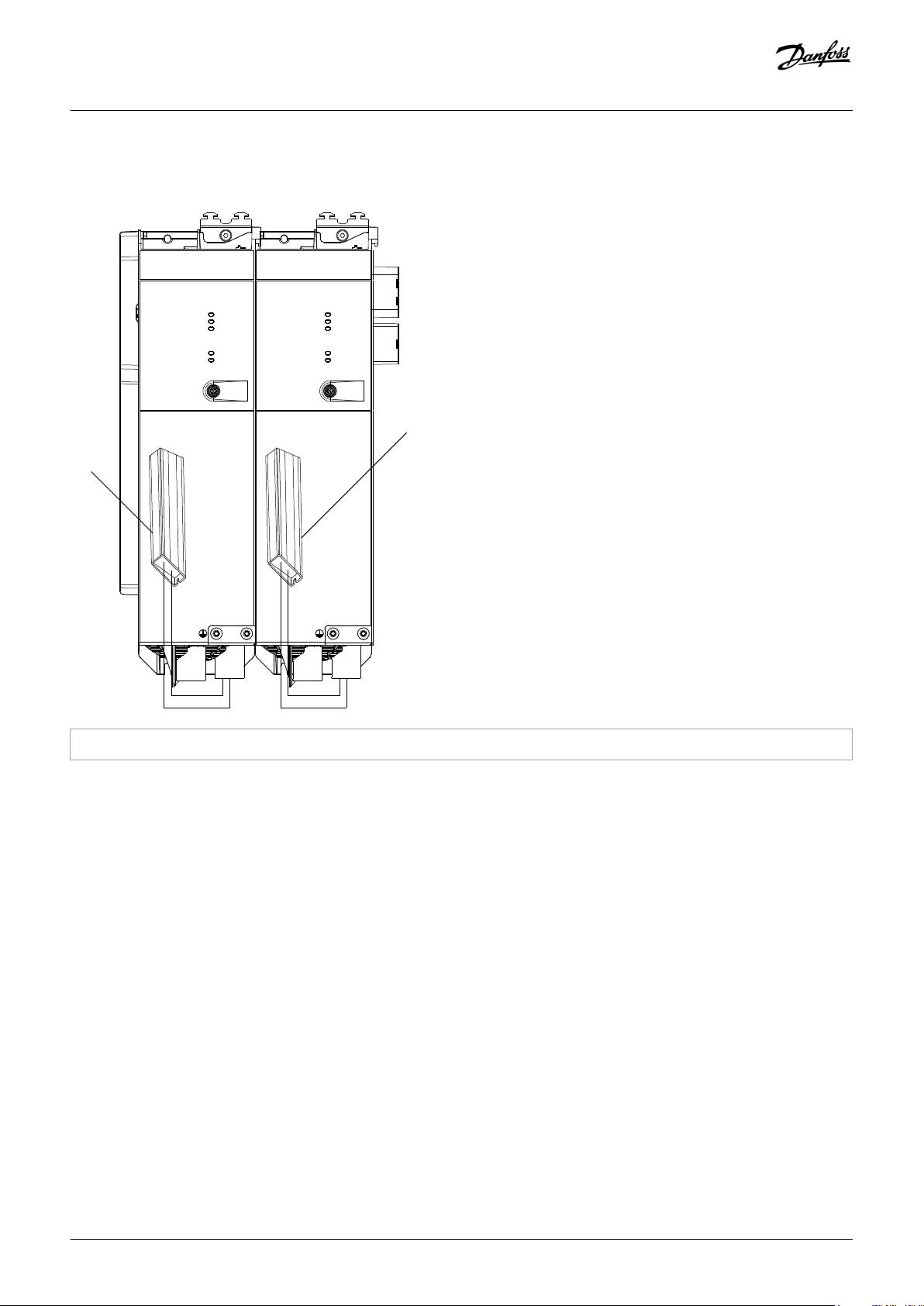
STATUS PSM
DEV
SVS ST
NET ST
LINK/ACT
X1
X2
LCP
STATUS PSM
DEV
SVS ST
NET ST
LINK/ACT
X1
X2
LCP
1
1
e30bh424.10
PSM 510
PSM 510
Operating Guide | VLT® Multiaxis Servo Drive MSD 510 System
Electrical Installation
1 Internal brake resistor
Illustration 60: Connection of Brake Resistor on 2 PSM 510 Modules in Parallel
Danfoss A/S © 2019.10
AQ262450196490en-000101 / 175R1170| 79
Page 80

Operating Guide | VLT® Multiaxis Servo Drive MSD 510 System
Commissioning
6 Commissioning
6.1 Warnings for Commissioning
WARNING
UNINTENDED START
The MSD 510 system contains servo drives, the PSM 510, and DAM 510 that are connected to the electrical supply network and
can start running at any time. This may be caused by a fieldbus command, a reference signal, or clearing a fault condition. Servo
drives and all connected devices must be in good operating condition. A deficient operating condition may lead to death,
serious injury, damage to equipment, or other material damage when the unit is connected to the electrical supply network.
Take suitable measures to prevent unintended starts.
-
6.2 Pre-Commissioning Checklist
Context:
Always complete these checks before initial commissioning and before commencing operation after extended downtime or storage.
Procedure
1. Check if all the threaded connectors of mechanical and electrical components are firmly tightened.
2. Check if the free circulation of cooling air (inlet and outlet) is assured.
3. Check if the electrical connections are correct.
4. Ensure that contact protection is in place for rotating parts and surfaces that can become hot.
5. If using the STO functionality, conduct the functional safety concept commissioning test (see
8.8 Commissioning Test).
6.3 SDM 511/SDM 512 Configuration Parameter and Drive Commissioning
6.3.1 Configuration Parameter Subtool
The Configuration Parameter subtool is the VLT® Servo Toolbox subtool for configuring:
• Motor data
• Application data
• Control data
• Input/output configurations
• External encoder
80 | Danfoss A/S © 2019.10
AQ262450196490en-000101 / 175R1170
Page 81

e30bh657.10
1 2 3
e30bh658.10
Operating Guide | VLT® Multiaxis Servo Drive MSD 510 System
Commissioning
1 Save/Save as button
3 Write configuration to device button
Illustration 61: Configuration Parameter Subtool
The configuration parameters are stored in a file.
• Click on the Read configuration from device button [2] to load the file.
• Click on the Save/Save as button [1] to save the file locally.
• Click on the Write configuration to device button [3] to transfer the file to a device. Power cycle the device to activate the transferred
configuration.
2 Read configuration from device button
NOTICE
Refer to the subtool for a detailed description of each parameter.
-
6.3.2 Drive Commissioning Subtool
The Drive Commissioning subtool is the VLT® Servo Toolbox subtool for carrying out commissioning tasks, such as:
• Motor feedback adjustment
• Resolver amplitude calibration
• Inertia measurement
Illustration 62: Drive Commissioning Subtool
Danfoss A/S © 2019.10
AQ262450196490en-000101 / 175R1170| 81
Page 82

Operating Guide | VLT® Multiaxis Servo Drive MSD 510 System
Commissioning
6.4 EtherCAT® ID Assignment
EtherCAT® needs no special ID assignment (IP address). Special ID assignment is only required when using indirect communication via
the VLT® Servo Toolbox software.
6.5 Ethernet POWERLINK® ID Assignment
6.5.1 Overview
Ethernet POWERLINK® master communication must not be active when using the VLT® Servo Toolbox to assign IDs to the devices. ID
assignment via the VLT® Servo Toolbox is only possible when acyclic Ethernet POWERLINK® communication is used. If Ethernet
POWERLINK® cyclic communication is already started, perform a power cycle to stop it.
Detach the PLC and carry out a power cycle before setting IDs. Alternatively, in the POWERLINK® interface, restart the PLC in Service
Mode while parameter Basic Ethernet in Service Mode is set to Basic Ethernet enabled.
6.5.2 Single Device ID Assignment
When assigning an ID to a single device, use the Device Information window in the VLT® Servo Toolbox (see the VLT® Servo Drive
System ISD 510, DSD 510, MSD 510 Programming Guide for further information).
Setting an ID to a device can also be done via the LCP.
6.5.2.1 Setting the Node ID Directly on a Servo Drive or on the System Modules
Context:
All IP-related parameters are located in parameter group 12-0* IP Settings. According to the Ethernet POWERLINK® standard, the IP
address is fixed to 192.168.100.xxx. The last number is the value in parameter 12-60 Node ID. For parameter 12-02 Subnet Mask, the IP
address is fixed to 255.255.255.0 and cannot be changed.
Procedure
1. Attach the LCP to the servo drive or system module for which the Node ID should be changed.
2. Press the Hand On button for >1 s to make the LCP the controlling interface.
3. Press the Main Menu button then scroll down to submenu 12-** Ethernet and press OK.
4. Scroll down to submenu 12-6* Ethernet POWERLINK and press OK.
5. Change the PSM 510/DAM 510 node ID to the desired value (1–239).
6. Press OK to confirm the selection then wait for the ID assignment procedure to complete.
7. Carry out a power cycle to ensure that all ID changes are in effect and operational on the fieldbus.
6.5.2.2 Setting the Node ID for a Single Servo Drive via the Power Supply Module (PSM 510) or
Decentral Access Module (DAM 510) via the LCP
Context:
It is also possible to change the Node ID of a servo drive when the LCP is connected to the PSM 510 or DAM 510. This functionality is
contained in parameter group 54-** ID Assignment in subgroup 54-1* Manual.
82 | Danfoss A/S © 2019.10
AQ262450196490en-000101 / 175R1170
Page 83

Operating Guide | VLT® Multiaxis Servo Drive MSD 510 System
Procedure
1. Attach the LCP to the PSM 510/DAM 510 that is connected to the servo drives and system modules for which the Node ID should be
changed.
2. Press the Hand On button for >1 s to make the LCP the controlling interface for the PSM 510/DAM 510.
3. Press the Main Menu button then scroll down to submenu 12-** Ethernet and press OK.
4. Scroll down to submenu 12-6* Ethernet POWERLINK and press OK.
5. Change the PSM 510/DAM 510 node ID to the desired value (1–239) by pressing the OK button.
6. Return to the Main Menu and select parameter 54-** ID Assignment.
7. Select parameter 54-1* Manual.
8. PSM 510 only: In parameter 54-01 Epl id assignment line, select either Ethernet port X1 or X2. The PSM 510 will assign IDs to the
selected device via the selected port and the fieldbus network. On DAM 510 port, X2 will be used automatically.
9. Select parameter 54-12 Epl ID assignment start id then select a valid value (1–239). The value will be assigned to the device at the
specified position index. The PSM 510/DAM 510 connected to the LCP is at position 0 and the 1st reachable device on the selected
port is position index 1 and so on.
10. Select parameter 54-14 Manual Epl ID assignment start and change the status from [0] ready to [1] start.
11. Press OK to confirm the selection then wait for the ID assignment procedure to complete.
12. Check that the ID assignment was completed successfully using parameters:
A Parameter 54-15 Epl ID assignment state
B Parameter 54-16 Epl ID assignment error code
C Parameter 54-17 Epl ID assignment device count
13. Carry out a power cycle to ensure that all ID changes are in effect and operational on the fieldbus.
If an error occurs during ID assignment, the detected error is shown on the LCP. The following errors may be reported:
• Invalid NMT state
• Invalid comment
• Invalid Ethernet port
• Invalid node ID
• ID assignment failed
• Duplicate MAC address
• Invalid SW version
• Incomplete assignment
• No device found
• Internal error
Commissioning
6.5.3 Multiple Device ID Assignment
When assigning IDs to several devices (for example, when setting up a new network), use the VLT® Servo Toolbox subtool DAM ID
assignment (see the VLT® Servo Drive System ISD 510, DSD 510, MSD 510 Programming Guide for further information).
Setting the IDs of all the servo drives connected to a Decentral Access Module (DAM 510) or Power Supply Module (PSM 510) at the
same time can also be done via the LCP when it is connected to the DAM 510/PSM 510.
Danfoss A/S © 2019.10
AQ262450196490en-000101 / 175R1170| 83
Page 84

Operating Guide | VLT® Multiaxis Servo Drive MSD 510 System
Commissioning
6.5.3.1 Setting the Node IDs of all Servo Drives and System Modules on a Decentral Access Module
(DAM 510)/Power Supply Module (PSM 510) Line
Context:
The automatic PSM 510/DAM 510 ID assignment is used for automatically setting the Node IDs on all servo drives and system modules
for a specified PSM 510/DAM 510 line. This functionality is contained in parameter group 54- ** ID Assignment in subgroup 54-0*
Automatic.
Procedure
1. Attach the LCP to the PSM 510/DAM 510 that is connected to the servo drives and system modules for which the Node ID should be
changed.
2. Press the Hand On button for >1 s to make the LCP the controlling interface for the PSM 510/DAM 510.
3. Press the Main Menu button then scroll down to submenu 12-** Ethernet and press OK.
4. Scroll down to submenu 12-6* Ethernet POWERLINK and press OK.
5. Change the PSM 510/DAM 510 node ID to the desired value (1–239) by pressing the OK button.
6. Return to the Main Menu and select parameter 54-** ID Assignment.
7. Select parameter 54-0* Automatic.
8. PSM 510 only: In parameter 54-01 Epl id assignment line, select either Ethernet port X1 or X2. The PSM 510 will assign IDs to the
selected device via the selected port and the fieldbus network. On DAM 510 port, X2 will be used automatically.
9. Select parameter 54-02 Epl ID assignment start id then select a valid value (1–239). The value will be assigned to the device at the
specified position index. The PSM 510/DAM 510 connected to the LCP is at position 0 and the 1st reachable device on the selected
port is position index 1 and so on.
10. Select parameter 54-03 Automatic Epl ID assignment start and change the status from [0] ready to [1] start.
11. Press OK to confirm the selection then wait for the ID assignment procedure to complete.
12. Check that the ID assignment was completed successfully using parameters:
A Parameter 54-04 Epl ID assignment state
B Parameter 54-05 Epl ID assignment error code
C Parameter 54-06 Epl ID assignment device count
13. Carry out a power cycle to ensure that all ID changes are in effect and operational on the fieldbus.
If an error occurs during ID assignment, the detected error is shown on the LCP. The following errors may be reported:
• Invalid NMT state
• Invalid comment
• Invalid Ethernet port
• Invalid node ID
• ID assignment failed
• Duplicate MAC address
• Invalid SW version
• Incomplete assignment
• No device found
• Internal error
6.6 PROFINET® ID Assignment
Each PROFINET® device needs a device name and an IP address. The IP address and the device name are assigned by the I/O controller,
when the connection to the I/O device is established.
84 | Danfoss A/S © 2019.10
AQ262450196490en-000101 / 175R1170
Page 85

Operating Guide | VLT® Multiaxis Servo Drive MSD 510 System
Commissioning
The IP address assignment is also required when using indirect communication via the VLT® Servo Toolbox software (see the VLT
Servo Drive System ISD 510, DSD 510, MSD 510 Programming Guide for further information).
The IP address and the device name can also be assigned using PRONETA, a free tool that supports in the analysis and configuration of
PROFINET® networks.
®
6.7 Power-Up Time
The maximum power-up time for the system components is 15 s. This means the time from supplying the system with auxiliary voltage
to the module being initialized completely.
The power-up time stated is an indicative time. The exact status of the module can be seen via the statusword.
NOTICE
Do not operate any of the system modules until they are all powered up correctly.
-
If 2 PSM 510 modules are mounted in parallel, power up both PSM 510 modules simultaneously (within a maximum delay
-
of 1 second).
6.8 System Module Charging Time
The charging time of the system is determined by the longest charging time of each individual system module.
The exact status of each module can be seen via the statusword.
NOTICE
Do not operate any of the system modules until they are charged up completely and are in state Operation enabled.
-
Table 16: DC-Link (UDC) Charging Time for PSM 510, DAM 510, and ACM 510
Specification Unit PSM 510 DAM 510 ACM 510
UDC charging time s 2.0 2.0 3.5
Table 17: DC-Link (UDC) Charging Time for SDM 511
Specification Unit SDM 511
2.5 A
UDC charging time s 2.0
SDM 511
5 A
SDM 511
10 A
SDM 511
20 A
Danfoss A/S © 2019.10
AQ262450196490en-000101 / 175R1170| 85
Page 86

Operating Guide | VLT® Multiaxis Servo Drive MSD 510 System
Table 18: DC-Link (UDC) Charging Time for SDM 512
Commissioning
Specification Unit SDM 512
2 x 2.5 A
UDC charging time s 2.0
SDM 512
2 x 5 A
SDM 512
2 x 10 A
6.9 Switching on the MSD 510 System
Complete the cabling of the MSD 510 system before applying power to the Servo Drive Modules (SDM 511/SDM 512). This cabling
provides the supply voltage and the communication signals for the MSD 510 system. This is a fundamental requirement for operation
of the servo drives.
The MSD 510 system is switched on by supplying the Power Supply Module (PSM 510) with U
passed on to all connected system modules and only the control units of the connected modules are running. The system is ready for
operation when mains and STO are supplied.
. This supply is then automatically
AUX
6.9.1 Procedure for Switching on the MSD 510 System
Procedure
1. Switch on U
2. Switch on the mains.
3. Set the PSM 510 to state Operation enabled.
power to enable communication to the PSM 510, DAM 510, and SDM modules to be established.
AUX
Now the system modules are ready for operation.
4. Set the DAM 510 to state Operation enabled.
6.10 Libraries
The libraries provided for the MSD 510 system can be used in:
• TwinCAT® V2
• SIMOTION SCOUT® V4.4 and V4.5:
- C240 from V4.4
- D410-2 from V4.4
- D425-2 from V4.4
- D435-2 from V4.4
- D445-2 from V4.4
- D455-2 from V4.4
- P320 from V4.4
• Automation Studio™ environment (version 3.0.90 and 4.x, supported platform SG4) to easily integrate the functionality without the
need for special motion run-time on the controller.
• TiA from V13
The provided function blocks conform to the PLCopen® standard. Knowledge of the underlying fieldbus communication and/or the
CANopen® CiA DS 402 profile is not necessary.
86 | Danfoss A/S © 2019.10
AQ262450196490en-000101 / 175R1170
Page 87

Operating Guide | VLT® Multiaxis Servo Drive MSD 510 System
The library contains:
• Function blocks for controlling and monitoring the ISD 510/DSD 510 servo drives, servo drive modules SDM 511/SDM 512, and the
system modules.
• Function blocks for all available motion commands of the ISD 510/DSD 510 servo drives and SDM 511/SDM 512 servo drive
modules.
• Function blocks for controlling and monitoring the PSM 510, DAM 510, and ACM 510.
• Function blocks and structures for creating Basic CAM profiles.
• Function blocks and structures for creating Labeling CAM profiles.
Commissioning
6.11 Programming with Automation Studio™
6.11.1 Requirements for Programming with Automation Studio™
The following files are required to integrate the ISD 510/DSD 510 servo drives, the SDM 511/SDM 512 servo drive modules, and the
system modules into an Automation Studio™ project:
• Package of libraries for the MSD 510 servo system: Danfoss_VLT_ServoMotion_V_x_y_z.zip
• XDD file (XML Device Description) for the standard ISD 510 servo drive: 0x0300008D_ISD510_S.xdd
• XDD file (XML Device Description) for the advanced ISD 510 servo drive: 0x0300008D_ISD510_A.xdd
• XDD file (XML Device Description) for the standard DSD 510 servo drive: 0x0300008D_DSD510_S.xdd
• XDD file (XML Device Description) for the advanced DSD 510 servo drive: 0x0300008D_DSD510_A.xdd
• XDD file (XML Device Description) for the SDM 511/SDM 512 servo drive module: 0x0300008D_SDM510.xdd
• XDD file (XML Device Description) for the Power Supply Module (PSM 510): 0x0300008D_PSM.xdd
• XDD file (XML Device Description) for the Decentral Access Module (DAM 510): 0x0300008D_DAM.xdd
• XDD file (XML Device Description) for the Auxiliary Capacitors Module (ACM 510): 0x0300008D_ACM.xdd
6.11.2 Creating an Automation Studio™ Project
The procedures described in this chapter apply to Automation Studio™ Versions 3.0.90 and V4.x unless otherwise specified.
Information on how to install Automation Studio™ can be found in detail in the Automation Studio™ help. Open the B&R Help Explorer
and go to [Automation software → Software Installation → Automation Studio].
Information on how to create a project in Automation Studio™ can be found in detail in the Automation Studio™ help.
V3.0.90:
Open the B&R Help Explorer and go to [Automation Software → Getting Started → Creating programs with Automation Studio → First
project with X20 CPU].
V4.x:
Open the B&R Help Explorer and go to [Automation Software → Getting Started → Creating programs with Automation Studio →
Example project for a target system with CompactFlash].
Danfoss A/S © 2019.10
AQ262450196490en-000101 / 175R1170| 87
Page 88

Operating Guide | VLT® Multiaxis Servo Drive MSD 510 System
Commissioning
6.11.3 Including the Servo Motion Libraries into an Automation Studio™ Project
Procedure
1. In the Logical View, open the menu entry [File → Import...].
2. In the next window, select the Danfoss_VLT_ServoMotion_V_x_y_z.zip file (according to the location on the hard drive).
3. Click on Open.
4. Assign the libraries to the CPU in the next window.
5. Click on Finish. Now the libraries are integrated into the Automation Studio™ project.
A new folder containing the ISD libraries is created during integration:
• DDS_Drive
- Contains program organization units (POUs) defined by PLCopen® (name starting with MC_) and POUs defined by Danfoss
(name starting with DD_). The Danfoss POUs provide additional functionality for the axis.
- It is possible to combine POUs defined by PLCopen® with POUs defined by Danfoss.
- The names of the POUs that target the servo drive all end with _DDS.
• DDS_PSM
- Contains POUs defined by Danfoss (name starting with DD_) and provide the functionality for the Power Supply Module
(PSM).
- The names of the POUs that target the PSM all end with _PSM.
• DDS_DAM
- Contains POUs defined by Danfoss (name starting with DD_) and provide the functionality for the Decentral Access
Module (DAM).
- The names of the POUs that target the DAM all end with _DAM.
• DDS_ACM
- Contains POUs defined by Danfoss (name starting with DD_) and provide the functionality for the Auxiliary Capacitors
Module (ACM).
- The names of the POUs that target the ACM all end with _ACM.
• DDS_BasCam
- Contains POUs for the creation of basic CAMs.
• DDS_LabCam
- Contains POUs for the creation of labeling CAMs.
• DDS_Intern
- Contains POUs that are needed internally for the libraries.
- Do not use these POUs in an application.
When integrating the DDS_Drive package, some standard libraries are integrated automatically, unless they are already part of
the project.
NOTICE
- Do not remove these libraries otherwise the Danfoss servo motion libraries will not work.
6.11.4 Constants within the DDS_Drive Library
Inside the library, the following lists of constants are defined:
88 | Danfoss A/S © 2019.10
AQ262450196490en-000101 / 175R1170
Page 89

Operating Guide | VLT® Multiaxis Servo Drive MSD 510 System
• Danfoss_VLT_ServoMotion
- Contains the version information of the library.
• DDS_AxisErrorCodes
- Constants for error codes of the axis.
- Error codes can be read using the function block MC_ReadAxisError_DDS and/or DD_ReadAxisWarning_DDS.
• DDS_AxisTraceSignals
- Constants for the trace signals of the axis.
- Intended to be used with the function block DD_Trace_DDS.
• DDS_BasCam
- Constants for the creation of basic CAMs.
• DDS_CamParsingErrors
- Constants for parsing problems of a CAM.
- Error reason is returned by function block MC_CamTableSelect_DDS.
• DDS_FB_ErrorConstants
- Constants for errors inside POUs.
- The reason is given in an output ErrorInfo.ErrorID that is available in all POUs.
• DDS_Intern
- Constants which are needed internally for the library.
- They are not intended to be used in an application.
• DDS_LabCam
- Constants for the creation of labeling CAMs.
• DDS_SdoAbortCodes
- Constants for errors concerning reading and writing of parameters.
- The reason is given in an output AbortCode that is available in several POUs.
• PSM_ErrorCodes
- Constants for error codes of the Power Supply Module (PSM 510).
- Error codes can be read using the function block DD_ReadPsmError_PSM and/or DD_ReadPsmWarning_PSM.
• PSM_TraceSignals
- Constants for the trace signals of the Power Supply Module (PSM 510).
- Intended to be used with the function block DD_Trace_PSM.
• DAM_ErrorCodes
- Constants for error codes of the Decentral Access Module (DAM 510).
- Error codes can be read using the function block DD_ReadDamError_DAM and/or DD_ReadDamWarning_DAM.
• DAM_TraceSignals
- Constants for the trace signals of the Decentral Access Module (DAM 510).
- Intended to be used with the function block DD_Trace_DAM.
• ACM_ErrorCodes
- Constants for error codes of the Auxiliary Capacitors Module (ACM 510).
- Error codes can be read using the function block DD_ReadAcmError_ACM and/or DD_ReadAcmWarning_ACM.
• ACM_TraceSignals
- Constants for the trace signals of the Auxiliary Capacitors Module (ACM 510).
- Intended to be used with the function block DD_Trace_ACM.
Commissioning
Danfoss A/S © 2019.10
AQ262450196490en-000101 / 175R1170| 89
Page 90
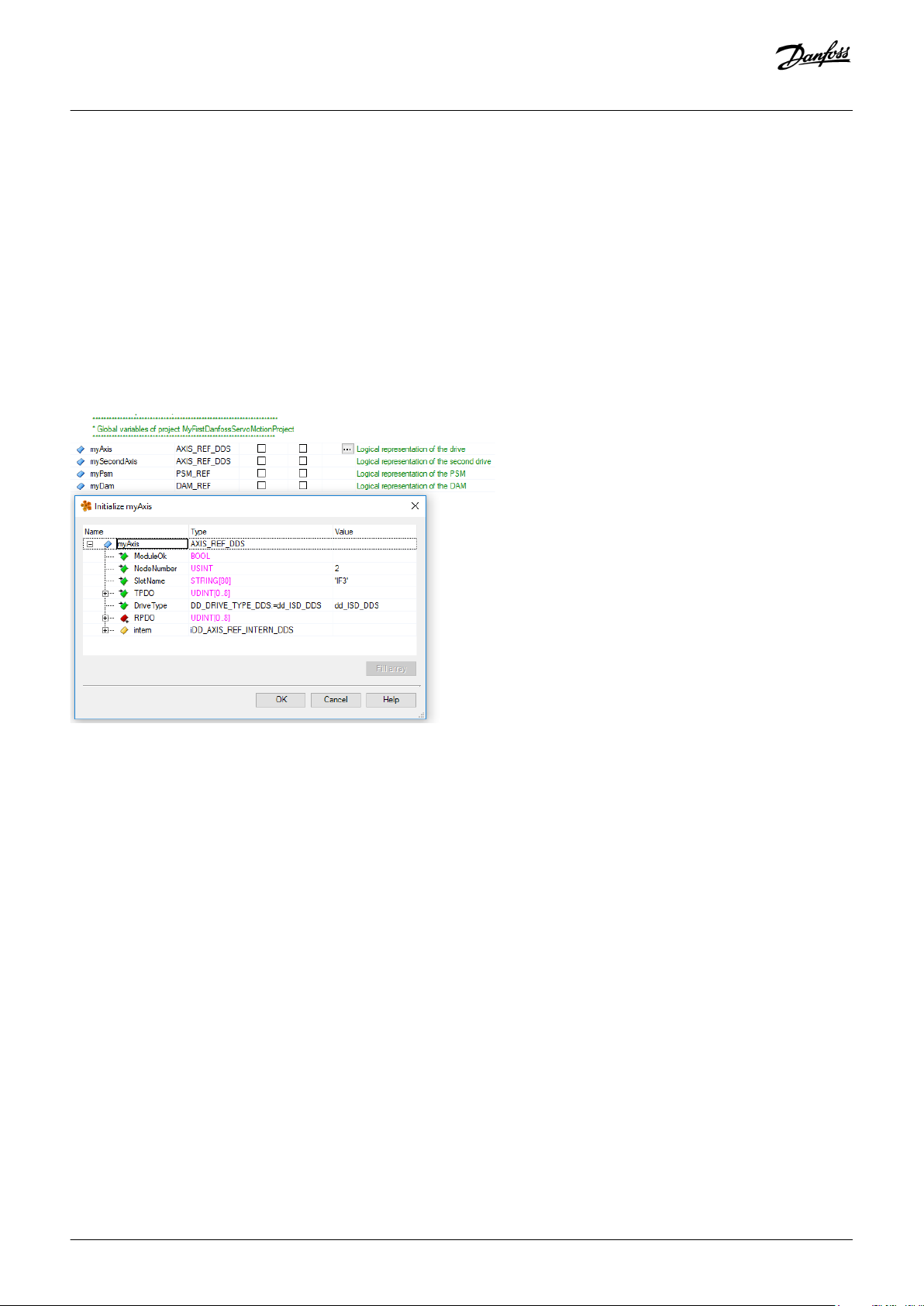
Operating Guide | VLT® Multiaxis Servo Drive MSD 510 System
Commissioning
6.11.5 Instantiating AXIS_REF_DDS in Automation Studio™
Procedure
1. Create 1 instance of function block AXIS_REF_DDS (located in folder DDS_Drive) for every SDM 511/SDM 512 drive module and
servo drive that has to be controlled or monitored.
2. To create a link to the physical servo drive, link each instance of AXIS_REF_DDS to 1 physical servo drive. This makes it the logical
representation of 1 physical servo drive.
Open the Logical View.
Initialize each instance with its node number and the slot name it is connected to (for example, IF3).
Initialize each instance of a drive with its DriveType.
Example:
Illustration 63: Instantiation of AXIS_REF_DDS and Setting of Initial Values
6.11.6 Instantiating PSM_REF in Automation Studio™
Procedure
1. Create 1 instance of function block PSM_REF (located in folder DDS_PSM) for every Power Supply Module (PSM) that has to be
controlled or monitored.
2. To create a link to the physical PSM, link each instance of PSM_REF to 1 physical PSM. This makes it the logical representation of 1
physical PSM.
Open the Logical View.
Initialize each instance with its node number and the slot name it is connected to (for example, IF3).
90 | Danfoss A/S © 2019.10
AQ262450196490en-000101 / 175R1170
Page 91

Operating Guide | VLT® Multiaxis Servo Drive MSD 510 System
Commissioning
6.11.7 Instantiating DAM_REF in Automation Studio™
Procedure
1. Create 1 instance of function block DAM_REF (located in folder DDS_DAM) for every Decentral Access Module (DAM) that has to be
controlled or monitored.
2. To create a link to the physical DAM, link each instance of DAM_REF to 1 physical DAM. This makes it the logical representation of 1
physical DAM.
Open the Logical View.
Initialize each instance with its node number and the slot name it is connected to (for example, IF3).
6.11.8 Instantiating ACM_REF in Automation Studio™
Procedure
1. Create 1 instance of function block ACM_REF (located in folder DDS_ACM) for every Auxiliary Capacitors Module (ACM) that has to
be controlled or monitored.
2. To create a link to the physical ACM, link each instance of ACM_REF to 1 physical ACM. This makes it the logical representation of 1
physical ACM.
Open the Logical View.
Initialize each instance with its node number and the slot name it is connected to (for example, IF3).
6.11.9 Importing a Servo Drive into Automation Studio™
Context:
NOTICE
For each physical servo drive, add 1 entry to the Physical View of Automation Studio™.
-
Danfoss A/S © 2019.10
AQ262450196490en-000101 / 175R1170| 91
Page 92

e30bh513.10
Operating Guide | VLT® Multiaxis Servo Drive MSD 510 System
Commissioning
6.11.9.1 Version V3.0.90
Procedure
1. Select the menu entry [Tools → Import Fieldbus Device...].
2. Select the XDD file (for example, 0x0300008D_ISD510_S.xdd or 0x0300008D_ISD510_A.xdd) from its location on the hard drive. This
import only needs to be done once per project. The device is then known to Automation Studio™.
3. Now add the SDM 511/SDM 512 drive module or servo drive to the Ethernet POWERLINK® interface of the controller in the Physical
View:
Right-click on the controller in the Physical View and select [Open POWERLINK].
Right-click on the interface and select Insert...
In the Select controller module window, select the servo drive in the group POWERLINK Devices.
Click on Next.
In the next window, enter the node number of the servo drive.
Illustration 64: Adding a Servo Drive to the Project in V3.0.90
92 | Danfoss A/S © 2019.10
AQ262450196490en-000101 / 175R1170
Page 93
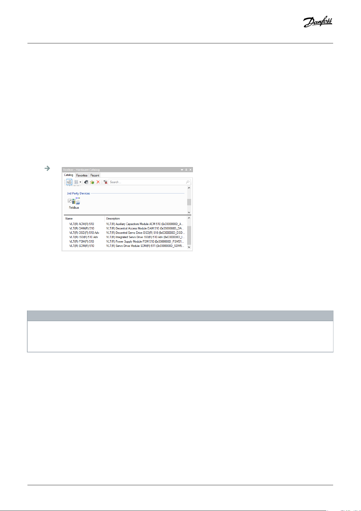
e30bh514.10
Operating Guide | VLT® Multiaxis Servo Drive MSD 510 System
Commissioning
6.11.9.2 Version V4.x
Procedure
1. Select the menu entry [Tools → Import Fieldbus Device...].
2. Select the XDD file (for example, 0x0300008D_ISD510_S.xdd or 0x0300008D_ISD510_A.xdd) from its location on the hard drive. The
device is then known to Automation Studio™.
3. Now add the SDM 511/SDM 512 drive module or servo drive to the Ethernet POWERLINK® interface of the controller in the Physical
View:
Select the menu entry [Open → System Designer] to show the System Designer.
To add a hardware module to the Physical View or System Designer, select the servo drive in the group POWERLINK in the Hardware
Catalog toolbox.
Drag the selected module to the desired position to connect it to the selected hardware module, network interface, or slot.
To change the node number, right-click on the device and select [Node Number → Change Node Number].
Illustration 65: Adding a Servo Drive to the Project in V4.x
6.11.10 Importing PSM 510, DAM 510 and ACM 510 into Automation Studio™
Context:
NOTICE
For each physical Power Supply Module (PSM 510), Decentral Access Module (DAM 510), and Auxiliary Capacitors Module
-
(ACM 510), add 1 entry to the Physical View of Automation Studio™.
Danfoss A/S © 2019.10
AQ262450196490en-000101 / 175R1170| 93
Page 94
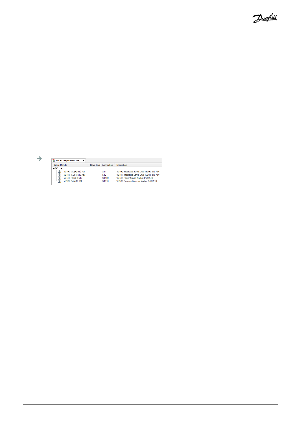
e30bh515.10
Operating Guide | VLT® Multiaxis Servo Drive MSD 510 System
Commissioning
6.11.10.1 Version V3.0.90
Procedure
1. Select the menu entry [Tools → Import Fieldbus Device...].
2. Select the XDD file for the PSM 510, DAM 510, or ACM 510 from its location on the hard drive. This import only needs to be done
once per project. The device is then known to Automation Studio™.
Power Supply Module (PSM 510): 0x0300008D_PSM.xdd
Decentral Access Module (DAM 510): 0x0300008D_DAM.xdd
Auxiliary Capacitors Module (ACM 510): 0x0300008D_ACM.xdd
3. Now add the PSM 510, DAM 510, or ACM 510 to the Ethernet POWERLINK® interface of the controller in the Physical View:
Right-click on the controller in the Physical View and select [Open POWERLINK].
Right-click on the interface and select Insert....
In the Select controller module window, select the PSM 510, DAM 510, or ACM 510 in the group POWERLINK Devices.
Click on Next.
In the next window, enter the node number of the PSM 510, DAM 510, or ACM 510.
Illustration 66: 1 PSM 510, 1 DAM 510, and 2 ISD 510 Servo Drives Added to the Ethernet POWERLINK® Interface in V3.0.90
94 | Danfoss A/S © 2019.10
AQ262450196490en-000101 / 175R1170
Page 95
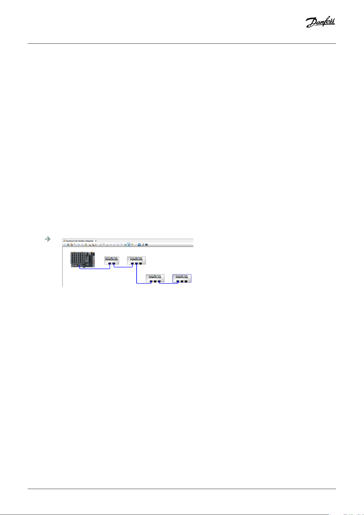
e30bh516.10
Operating Guide | VLT® Multiaxis Servo Drive MSD 510 System
Commissioning
6.11.10.2 Version V4.x
Procedure
1. Select the menu entry [Tools → Import Fieldbus Device...].
2. Select the XDD file for the PSM 510, DAM 510, or ACM 510 from its location on the hard drive. The device is then known to
Automation Studio™.
Power Supply Module (PSM 510): 0x0300008D_PSM.xdd
Decentral Access Module (DAM 510): 0x0300008D_DAM.xdd
Auxiliary Capacitors Module (ACM 510): 0x0300008D_ACM.xdd
3. Now add the PSM 510, DAM 510, or ACM 510 to the Ethernet POWERLINK® interface of the controller in the Physical View:
Select the menu entry[Open → System Designer] to show the System Designer.
To add a hardware module to the Physical View or System Designer, select the PSM 510, DAM 510, or ACM 510 in the group
POWERLINK in the Hardware Catalog toolbox.
Drag the selected module to the desired position to connect it to the selected hardware module, network interface, or slot.
To change the node number, right-click on the device and select [Node → Change Node Dumber].
PSM: Danfoss _VLT_R_PSM
DAM: Danfoss _VLT_R_DAM
ACM: Danfoss _VLT_R_ACM
Illustration 67: 1 PSM 510, 1 DAM 510, and 2 ISD 510 Servo Drives Added to the Ethernet POWERLINK
®
Interface in V4.x
Danfoss A/S © 2019.10
AQ262450196490en-000101 / 175R1170| 95
Page 96

Operating Guide | VLT® Multiaxis Servo Drive MSD 510 System
Commissioning
6.11.11 I/O Configuration and I/O Mapping
Procedure
1. Parameterize the I/O configuration of the SDM 511/SDM 512 drive modules or servo drives so that the library has access to all
necessary objects.
Right-click on the entry of the SDM 511/SDM 512 drive module or servo drive and select Open I/O Configuration in V3.0.90 and
Configuration in V4.x.
In the Channels section, change the Cyclic transmission of the following objects:
All sub-indexes of object 0x5050 (Lib pdo rx_I5050 ARRAY[]) to Write.
All sub-indexes of object 0x5051 (Lib pdo tx_I5051 ARRAY[]) to Read.
2. Parameterize the I/O configuration of the Power Supply Module (PSM 510), Decentral Access Module (DAM 510), and Auxiliary
Capacitors Module (ACM 510) so that the library has access to all necessary objects.
Right-click on the entry of the PSM/DAM/ACM and select Open I/O Configuration in V3.0.90 and Configuration in V4.x.
In the Channels section, change the Cyclic transmission of the following objects:
All sub-indexes of object 0x5050 (Lib pdo rx_I5050 ARRAY[]) to Write.
All sub-indexes of object 0x5051 (Lib pdo tx_I5051 ARRAY[]) to Read.
These settings configure the cyclic communication with the device. These parameters are required for the library to work.
NOTICE
- It is possible to use copy and paste to apply the same I/O configuration to multiple devices of the same type.
3. Set Module supervised to off for the servo drives and the PSM/DAM/ACM. The parameter is found in the I/O configuration of the
device.
96 | Danfoss A/S © 2019.10
AQ262450196490en-000101 / 175R1170
Page 97

e30bg341.10
e30bg342.10
Operating Guide | VLT® Multiaxis Servo Drive MSD 510 System
Commissioning
Illustration 68: I/O Configuration of an ISD 510 Device
Illustration 69: I/O Mapping after Successful Configuration
4. Map the inputs and outputs of the instance of the AXIS_REF_DDS function block and the physical data points of the ISD 510 servo
drive (here myAxis is an instance of AXIS_REF_DDS):
Danfoss A/S © 2019.10
AQ262450196490en-000101 / 175R1170| 97
Page 98

e30bg343.10
e30bg344.10
Operating Guide | VLT® Multiaxis Servo Drive MSD 510 System
Illustration 70: I/O Mapping of an ISD 510 Servo Drive
Commissioning
5. Map the inputs and outputs of the instance of the PSM_REF, DAM_REF, and ACM_REF function blocks and the physical data points
of the PSM/DAM/ACM accordingly.
6.11.12 Setting the PLC Cycle Time
Context:
The minimum cycle time is 400 µs. The servo system devices can run Ethernet POWERLINK® cycle times in multiples of 400 µs and
multiples of 500 µs. The devices are automatically parameterized by the PLC on start-up, depending on the Ethernet POWERLINK
®
configuration of the physical interface. The Ethernet POWERLINK® configuration can be accessed by right-clicking [CPU → Open IF3
POWERLINK Configuration] in the Physical View for V3.0.90 or [PLK → Configuration] for V4.x.
NOTICE
-
Ensure that the task cycle times of the PLC program and Ethernet POWERLINK® are the same. Otherwise, data could be lost
and performance reduced.
Illustration 71: Ethernet POWERLINK<® Configuration Window to Parameterize Ethernet POWERLINK® Cycle Time
Procedure for setting the PLC time in Automation Studio™
1. Right-click [CPU → Open Software Configuration] for V3.0.90 and [CPU → Configuration → Timing] for V4.x in the Physical View.
2. Ensure that the PLC cycle time is the same as the Ethernet POWERLINK® cycle time.
98 | Danfoss A/S © 2019.10
AQ262450196490en-000101 / 175R1170
Page 99

Operating Guide | VLT® Multiaxis Servo Drive MSD 510 System
Commissioning
6.11.13 Connecting to the PLC
Information on how to connect to the PLC can be found in detail in the Automation Studio™ Help.
Version V3.0.90:
Open the B&R Help Explorer and go to [Automation Software → Getting Started → Creating programs with Automation Studio → First
project with X20 CPU → Configure online connection].
Version V4.x:
Open the B&R Help Explorer and go to [Automation Software → Getting Started → Creating programs in Automation Studio →
Example project for a target system with CompactFlash].
6.12 Programming with TwinCAT®
6.12.1 Requirements for Programming with TwinCAT®
To integrate the ISD 510/DSD 510 servo drives, servo drive modules SDM 511/SDM 512, and the PSM 510, DAM 510, or ACM 510 into a
TwinCAT® project, the following files are required:
• Library for the MSD 510 servo system: Danfoss_VLT_ServoMotion_V_x_y_z.lib
• ESI file (EtherCAT® Slave Information) for the standard ISD 510 servo drive: Danfoss_ISD510_S.xml
• ESI file (EtherCAT® Slave Information) for the advanced ISD 510 servo drive: Danfoss_ISD510_A.xml
• ESI file (EtherCAT® Slave Information) for the standard DSD 510 servo drive: Danfoss_DSD510_S.xml
• ESI file (EtherCAT® Slave Information) for the advanced DSD 510 servo drive: Danfoss_DSD510_A.xml
• ESI file (EtherCAT® Slave Information) for the Servo Drive Module: Danfoss_SDM510.xml
• ESI file (EtherCAT® Slave Information) for the Power Supply Module: Danfoss_PSM510.xml
• ESI file (EtherCAT® Slave Information) for the Decentral Access Module: Danfoss_DAM510.xml
• ESI file (EtherCAT® Slave Information) for the Auxiliary Capacitor Module: Danfoss_ACM510.xml
6.12.2 Creating a TwinCAT® Project
Information on how to install TwinCAT® can be found in detail in the Beckhoff Information System (https://infosys.beckhoff.com/).
Open the information system and select [TwinCAT 2 → TwinCAT Quick Start → Installation].
Information on how to create a project in TwinCAT® can be found in detail in the Beckhoff Information System (https://
infosys.beckhoff.com/). Open the information system and select [TwinCAT 2 → TwinCAT Quick Start or TwinCAT 2 → TX1200 TwinCAT
PLC → TwinCAT PLC Control].
Danfoss A/S © 2019.10
AQ262450196490en-000101 / 175R1170| 99
Page 100

e30bh611.10
Operating Guide | VLT® Multiaxis Servo Drive MSD 510 System
6.12.3 Including the TwinCAT® Library into a TwinCAT® Project
Procedure
1. In the Resources tab of TwinCAT® PLC Control, open the Library Manager.
2. In the upper left area of the Library Manager window, right-click and select Additional Library....
3. Select the Danfoss_VLT_ServoMotion_V_x_y_z file (according to the location on the hard drive).
4. Click on Open. Now the libraries are integrated into the TwinCAT® PLC control project.
Commissioning
Illustration 72: Library Manager after Including the ServoMotion Library
Inside the library, the POUs are organized into folders:
100 | Danfoss A/S © 2019.10
AQ262450196490en-000101 / 175R1170
 Loading...