

Page 1

CONVERSION KITS FOR FRAMES MR8 AND MR9
INSTALLATION INSTRUCTIONS
Page 2

Page 3

MR8 AND MR9 CONVERSION KIT - INSTALLATION INSTRUCTION
3
2
1
4
5
7
6
8
4
9
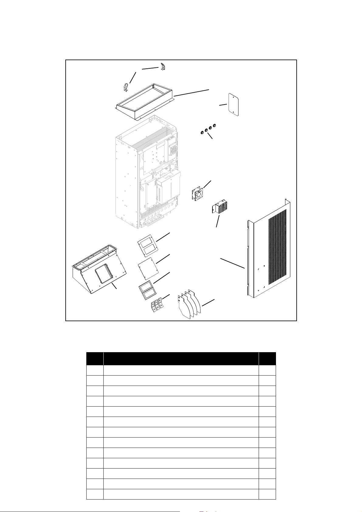
1.1 MR8 kit contents
MR8 conversion kit, sales code: ENC-EDMOUNTKIT-MR08
NOTE! Screws are included in the spare part kit.
Document ID: DPD01787, Revision: A, Release date: 17.11.2015
Figure 1.MR8 conversion kit
Table 1. MR8 conversion kit part list numbered according to the exploded view above
# Name of part Qty
1 MR8 inlet collar assembly 1
2 MR8 connection insulator 4
3 Output cable support 3
4 MR8 module fixing rail 4
5 MR8 front plate for cabinet 1
6 Internal fan 1
7 MR8 IP54 hole cover 1
8 MR8 outlet collar 1
9 Service hatch 1
Page 4
1.2 MR9 kit contents
1
2
3
5
4
6
7
8
9
10
11
12
13
MR9 conversion kit, sales code: ENC-EDMOUNTKIT-MR09
NOTE! Screws are included in the spare part kit.
Figure 2.MR9 conversion kit
# Name of part Qty
1 MR9 heatsink hatch IP21 1
2 MR9 heatsink hatch 1
3 MR10 compartment filter 2
4 MR9 connection insulator 4
5 Output cable support 3
6 MR9 front plate for cabinet 1
7 Module IP54 sidecover 1
8 Body plug 4
9 Lifting bracket 2
10 MR9 outlet collar assembly 1
11 MR9 power module internal fan shield 1
12 Axial fan 1
13 MR9 heatsink 1
Page 5

1.3 MR8 Installation instructions
EN Always make sure that the kit contains all components and they are in appropriate condition before starting the installa-
1
tion work.
FI Varmista aina, että varaosasarja sisältää kaikki tarvittavat komponentit, ja että komponentit ovat asianmukaisessa kun-
nossa ennen asennustyön aloittamista.
2
EN In IP21 and IP54 units only, remove the extension box
from the drive.
FI IP21 tai IP54 yksikön ollessa kyseessä, poista
optiomoduuli taajuusmuuttajasta.
3
4
EN Remove the front cover from the drive.
FI Poista taajuusmuuttajan etukansi.
EN Open the control unit cover and disconnect the fan wire
(X) from the control unit.
FI Avaa ohjausyksikön kansi ja irrota puhaltimen liitin (X)
ohjausyksiköstä.
X
Page 6

5
6
EN Remove the control unit.
FI Poista ohjausyksikkö.
EN Install the IP54 cover. Tighten the M4x8 screws to
torque 1.4Nm.
FI Asenna IP54 suojus. Kiristä M4x8 ruuvit 1.4Nm
tiukkuuteen.
Page 7

7
8
EN Install the fixing rails. Tighten the M5x12 screws to
torque 3.5Nm.
FI Asenna kiinnityskiskot. Kiristä M5x12 ruuvit 3.5Nm
tiukkuuteen.
EN Install internal fan, if necessary. Tighten the M4x50
screws to torque 0.8 Nm.
FI Asenna tarvittaessa uusi sisäpuhallin. Kiristä M4x50
ruuvit 0.8 Nm tiukkuuteen.
Page 8

9
EN Install the outlet collar. Tighten the M4x8 screws (4 pcs)
to torque 1.8 Nm.
FI Asenna ilmanpoistokaulus. Kiristä M4x8 ruuvit (4 kpl)
1.8 Nm tiukkuuteen.
10
11
EN In IP00 units only, remove the touch protection shield.
FI Poista kosketussuojus IP00 laitteista.
EN Remove the old connection insulators.
FI Poista vanhat liitoseristeet.
Page 9

12
X
1
EN Install the output cable supports. Tighten the M8 nuts to
torque 20 Nm.
FI Asenna lähtökaapeleiden kiskot. Kiristä M8 mutterit 20
Nm tiukkuuteen.
13
14
EN Install the drive into the cabinet.
15
FI Asenna taajuusmuuttuja kaappiin.
EN Install new connection insulators.
FI Asenna uudet liitoseristeet.
EN Install the inlet collar.
FI Asenna ilmansyöttökaulus
16
EN Install the front plate for cabinet. Tighten the M4x8
screws (4 pcs) to torque 1.2 Nm. Install the control
cable (X) through the plate aperture as shown in the
figure beside. Connect the internal fan into the
connector 1.
FI Asenna etulevy kaapitusta varten. Kiristä M4x8 ruuvit
(4 kpl) 1.2 Nm tiukkuuteen. Asenna ohjauskaapeli (X)
levyaukon kautta viereisen kuvan mukaisesti. Kytke
sisäpuhallin pistokkeeseen 1.
Page 10

1.4 MR9 Installation instructions
EN Always make sure that the kit contains all components, and they are in appropriate condition before starting the installa-
1
tion work.
FI Varmista aina, että varaosasarja sisältää kaikki tarvittavat komponentit, ja että komponentit ovat asianmukaisessa kun-
nossa ennen asennustyön aloittamista.
2
EN In IP21 and IP54 units only, remove the extension box
from the drive.
FI IP21 tai IP54 yksikön ollessa kyseessä, poista
optiomoduuli taajuusmuuttajasta.
3
EN Remove the front cover from the drive.
FI Poista taajuusmuuttajan etukansi.
Page 11

4
X
EN Open the control unit cover and disconnect the fan wire
(X) from the control unit.
FI Avaa ohjausyksikön kansi ja irrota puhaltimen liitin (X)
ohjausyksiköstä.
5
6
EN Remove the control unit.
FI Poista ohjausyksikkö.
EN Remove the side cover plate and install the body plugs.
FI Poista sivusuojus ja asenna suojatulpat.
Page 12

7
8
EN Install IP54 side cover. Tighten the M4x8 screws to
torque 1.8Nm.
FI Asenna IP54 sivusuojus. Kiristä M4x8 ruuvit 1.8Nm
tiukkuuteen.
EN Install internal fan and fan cover, if necessary. Tighten
the M4x50 screws to torque 0.8Nm and the M4x8
screws to torque 0.9Nm.
FI Asenna tarvittaessa sisäpuhallin ja sen suojus. Kiristä
M4x50 ruuvit 0.8Nm tiukkuuteen ja M4x8 ruuvit 0.9Nm
tiukkuuteen.
9
EN Install the outlet collar. Tighten the M4x6 screws (6 pcs)
to torque 1.8Nm.
FI Asenna ilmanpoistokaulus. Kiristä M4x6 ruuvit (6 kpl)
1.8Nm tiukkuuteen.
Page 13

10
EN Install the lifting lugs.Tighten the M8x30 screws to
torque 20Nm.
FI Asenna nostokorvakkeet. Kiristä M8x30 ruuvit 20Nm
tiukkuuteen.
11
12
13
EN Remove the old connection insulators.
FI Poista vanhat liitoseristeet.
EN Install the output cable supports. Tighten the M8 nuts to
torque 20 Nm.
FI Asenna lähtökaapeleiden kiskot. Kiristä M8 mutterit 20
Nm tiukkuuteen.
EN Install new connection insulators (4 pcs) in order to
protect U, V and W terminals.
FI Asenna uudet liitoseristeet (4 kpl) suojaamaan U, V ja
W riviliittimiä.
Page 14

14
X
1
A
EN Install IP21 heatsink hatch according to alternative A (if
B
filters are not installed). If filters are installed, install
heatsink hatch and filters according to alternative B.
Tighten the M5x8 screws to torque 1.8 Nm.
FI Asenna IP21 jäähdytyselementin suojus vaihtoehdon A
mukaisesti (jos suodattimia ei asenneta). Jos
suodattimet asennetaan, asenna jäähdytyselementin
suojus ja suodattimet vaihtoehdon B mukaisesti. Kiristä
M5x8 ruuvit 1.8 Nm tiukkuuteen.
EN Install the drive into the cabinet
15
FI Asenna taajuusmuuttuja kaappiin.
16
EN Install the front plate for cabinet. Tighten the M4x8
screws (5 pcs) to torque 1.2 Nm. Install the control
cable (X) through the plate aperture as shown in the
figure beside. Connect the internal fan into the
connector 1.
FI Asenna etulevy kaapitusta varten. Kiristä M4x8 ruuvit
(5 kpl) 1.2 Nm tiukkuuteen. Asenna ohjauskaapeli (X)
levyaukon kautta viereisen kuvan mukaisesti. Kytke
sisäpuhallin pistokkeeseen 1.
Page 15

Document ID:
Rev. A
 Loading...