

Page 1
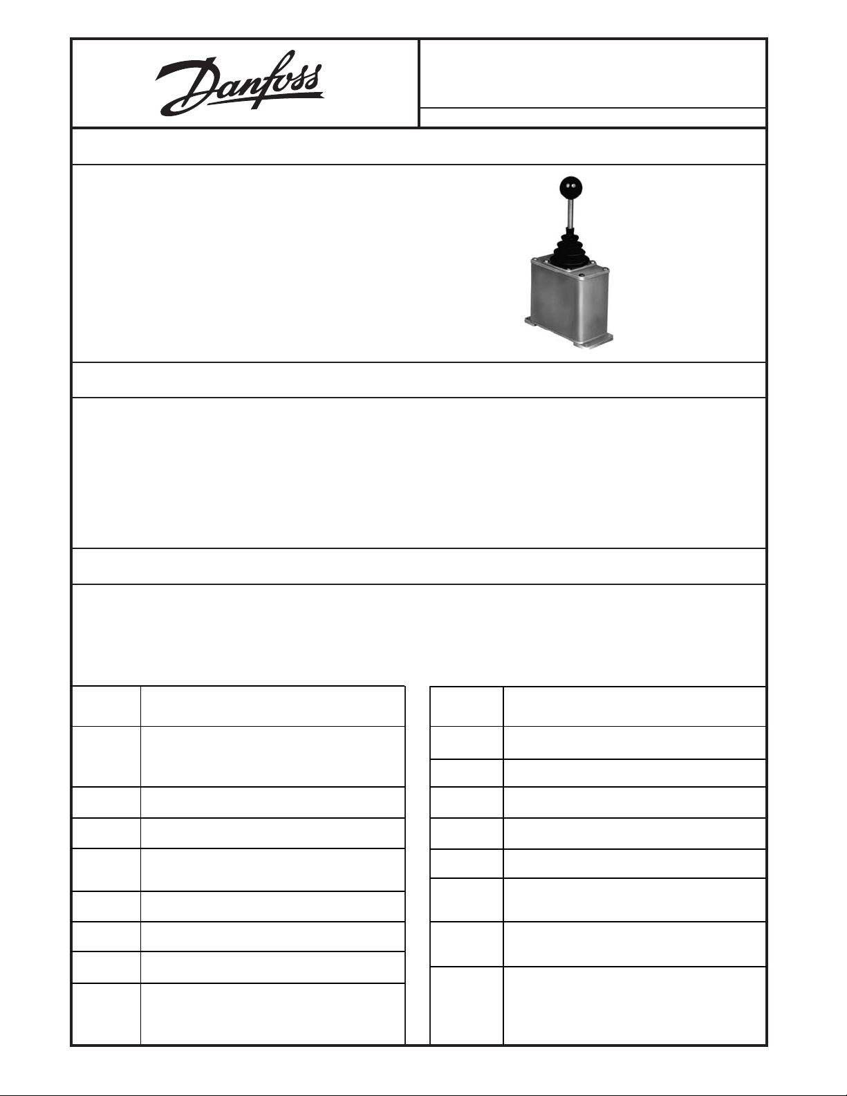
DESCRIPTION
The MCHXXX Control Handle is intended for use in openloop systems controlling Danfoss hydrostatic pumps with
an Electrical Displacement Control (EDC).
These Control Handles may also be used with an MCE101
Proportional Transmission Controller in pressure or
horsepower limiting applications.
The Control Handle is designed to provide a remote manmachine interface. In addition to proportional operation of
electrically controlled hydrostatics, switches may be incorporated to operate backup, alarm, brake, and neutral interlock circuits.
FEATURES
MCH Control Handle/EDC
Control Handles For
Electrical Displacement Controls (EDC)
BLN
95-9007-0101
Issued
July 2017
• Choice of three mounting styles with or without water
resistant case.
• Mechanical options include center lock, spring return,
friction held, and center detents.
• High torque handle actuation gives a realistic force feel.
• Easy installation.
• Shock and vibration resistant.
• Environmental hardened components designed for off-
road construction equipment.
• Optional switches in knobs.
• Optional cam operated switches.
• Optional electrical cable and connectors.
ORDERING INFORMATION
The following tabulation is the list of current standard production Control Handle models for EDCs. Behind each circuit (as
described in the Electrical Characteristics section of this bulletin) is the mounting, knob, and actuation which are available as
production models. For example, for the B1039 circuit there is MCH12AB1039, MCH41AB1039, and MCH51AB1039 in
production. Other combinations may be possible. Consult factory for availability.
CIRCUIT
NUMBER MOUNTING, KNOB AND ACTUATION
B1032 11A 11B 12A 12B 13B 21A 21B 21C 22A
22B 23A 26A 26B 29A 29B 31A 32B 40A
41A 41B 42A 42B 47A 48B 51A 51B 58A
B1035 11C 21C 29C 31C 41C 43C 51C 59C
CIRCUIT
NUMBER MOUNTING, KNOB AND ACTUATION
C1065 22B
C1067 11A 12B 21A 22A 22B 32A 41B 42B
C5168 11A 22B 32A 42B
B1039 11A 12A 41A 51A
B1042 11A 11B 12A 12B 21A 22A 22B 23A 25A
29B 41A 41B 42A 43B 48A
B3069 12A 22B 32B 41A 42A
B5087 11B 22B 41B 42B
B5093 11A 12B 22A 22B 41A 51B
C1033 11A 11B 12A 12B 13A 21A 21B 22A 22B
23A 29A 32B 41A 41B 42A 42B 43A 51A
51B 52A 52B 53A
D1029 11B 22B 29B
D1040 19A 21A 22B 31B 42B
D1043 11A 11B 12B 13A 13B 16B 21A 22B 23A
26B 29A 29B 32A 41A 41B 42B 51B 52B
D1058 11A 11B 12A 12B 21B 22A 22B 23A 41B
42B 45B 48A 52B
D1064 11A 11B 12A 12B 22A 22B 29B 41A 41B
42B 48A
1
© Copyright 2017, Danfoss (US) Company.
All rights reserved. Contents subject to
change.
Page 2
ORDERING INFORMATION
(continued)
CIRCUIT
NUMBER MOUNTING, KNOB AND ACTUATION
D1073 11B 12B 21A 21B 22B 23B 31B 41B 51B
52B
D1077 21A 21B 22B 41B 51A 51B
D1082 13A 21A 21B 22B 42B
D1089 42B 51B
D2155 48A
D3059 11B
D5129 11A 11B 22B 41A 41B
L2171 11A 11B 12A 12B 19A 21A 22B 42B
MCHXXX ORDERING SPECIFICATION CHART
M C H
X XXX X X X X
CIRCUIT
NUMBER MOUNTING, KNOB AND ACTUATION
M1068 11A 11B 12B 13A 21A 21B 22A 22B 28A
29B 41B 42A 42B 48A 51B 52A 58B 59A
M1083 11A 12B 19A 21A 22B 41A 51A 51B 52B
M1101 11B 12B 21A 22A 22B 41B 42B
M1112 22B 31B 41B 52B
M1122 21A 22B 41B 42B 48A
M1167 21A 32B 42B 51B
M1169 22B 41B 45B
TYPE OF
CONTROL KNOB
HANDLE
ACTUATION
MOUNTING
1 Base (surface) mount aluminum case
2 Top mount (drop-in) with plastic case
3 Top mount (drop-in) without plastic case
4 Panel mount with plastic case
5 Panel mount without plastic case
TYPE OF CONTROL KNOB
1 Non-locking
2 Center lock
3 Push button in knob
4 Tron maintained rocker switch (obsoleted)
5 Non-locking, no knob
6 3-position maintained rocker switch in knob
7 Tron momentary rocker switch (obsoleted)
8 Special (no handle or knob)
9 3-position momentary rocker switch in knob
C Maintained rocker and trigger switch
D Momentary rocker and lever switch
E Momentary rocker and trigger switch
HANDLE ACTUATION
A Spring-return, bi-directional
B Friction held, bi-directional
C Friction held, uni-directional
D Special (friction held, center detent only, no brake)
E Spring return, uni-directional (one direction
blocked, 30° movement)
ELECTRICAL
CHARACTERISTICS
CONNECTORMOUNTING SEE
ORDERING
INFORMATION
SECTION
ELECTRICAL CHARACTERISTICS
A Proportional, no switches
B Proportional, 12 Vdc center-off switch
C Proportional, 24 Vdc center-off switch
D Proportional, center-off and auxiliary switch
L Electronic PWM auxiliary switching
M 3-switches
N 4-switches
P 5-switches
R 2-switches
X Special
Y Special
Z Special
CONNECTOR
1 Terminal strip internal
2 Pigtail 60 inch with no connector
3 Pigtail with unsealed Packard connector
4 Pigtail with both halves of unsealed Packard
connector
5 Sealed Packard connector with mating half
6 Sealed Packard connector 4-pin male and female
7 Pigtail with sealed Packard connector
8 Pigtail sealed Deutsch connector
9 No connector / terminal strip
BLN 95-9007-0101
2
Page 3

TECHNICAL DATA
ELECTRICAL SPECIFICATIONS
OPERATING VOLTAGE RANGE
11-15 Vdc (12 Volt models)
10 Vdc (12 Volt proportional transmission controller
models)
22-30 Vdc (24 Volt models)
20 Vdc (24 Volt proportional transmission control-
ler models)
LOAD RESISTANCE
15-30 Ω
Danfoss single and dual-coil Electrical Displacement
Controls.
AUXILIARY SWITCH CURRENT CAPABILITY
V3L Microswitch (cam actuated)
3-amp, inductive at 28 Vdc
SM Microswitch (cam actuated)
2.5-amp, inductive at 28 Vdc
Rocker Switch (in knob)
2-amp, inductive at 28 Vdc
Push button Switch (in knob)
5-amp, inductive at 28 Vdc
MECHANICAL SPECIFICATIONS
HANDLE STROKE:
±30°
60° total travel
SPRING TORQUE
11 ± 4-in./lb. (1.2 ± 0.4-N-m) at center break away
18 ± 6-in./lb. (2.0 ± 0.7-N-m) at full stroke
DETENTE TORQUE (over & above friction drag):
10-in./lb. (1.1-N-m)
FRICTION DRAG:
13.5 ± 3-in./lb. (1.5 ± 0.3-N-m)
Friction is adjusted at brake assembly with a 5/32 English
Allen wrench and 3/8 open-ended wrench.
MOUNTING, TYPE OF KNOB, HANDLE ACTUATION
A wide range of options to the basic Control Handle allows it
be custom-tailored to each application. See Ordering Specification chart in Ordering Information.
MOUNTING (See Dimension Drawing)
1. BASE OR SURFACE MOUNT
Connection is via four screws to the flanges on the
bottom of the metal case.
2. TOP MOUNT WITH CASE
Connection is via two screws to an enlarged mounting
plate. Top mounting allows the entire handle to be
removed from above the panel. The case is made of
black nylon plastic.
3. TOP MOUNT WITHOUT CASE
Same as 2, but without case.
4. PANEL MOUNT WITH CASE
Connection is via four screws to the top plate that holds
the boot in place. The case is made of black nylon
plastic.
5. PANEL MOUNT WITHOUT CASE
Same as 4, but without case.
TYPE OF CONTROL KNOB (See Dimension Drawing)
1. NON-LOCKING
The non-locking handle has a standard ball knob. The
friction-held handle detents with a spring-loaded ball to
indicate null, while the spring-return handle has a springpreload indicating null.
2. CENTER-LOCK
The center-lock handle has a cylindrical knob and provides a positive center-lock that unlatches when the
operator pulls up on the knob.
3. NON-LOCKING, AUXILIARY SWITCH
This knob is teardrop shaped, with an auxiliary momentary push button switch on top. The switch is wired
through the handle shaft to the body with three wires
(common, normally open and normally closed).
5. NON-LOCKING, NO KNOB
The customer provides has own customized knob.
6. THREE POSITION MAINTAINED ROCKER SWITCH
IN KNOB
The cylindrical knob has a boot covering the three
position switch in the knob. The switch, wired through
the handle, is used for auxiliary functions.
9. THREE POSITION MOMENTARY ROCKER SWITCH
IN KNOB
This is the same as 6, but the switch returns to the center
position when released.
BLN 95-9007-0101
3
Page 4

HANDLE ACTUATION
HANDLE ACTUATION
(continued)
PERFORMANCE CURVE
A. SPRING-RETURN, BI-DIRECTIONAL
This handle uses a torsion spring to return to the
mechanical center position, and has 30 degrees of
handle throw on either side of center.
B. FRICTION-HELD, BI-DIRECTIONAL
This handle has an adjustable drag set with a clamptype brake, that holds the handle at the set position, and
has 30 degrees of handle throw on either side of the
center detent.
C. FRICTION-HELD, UNI-DIRECTIONAL
This handle has a high-resolution 60 degrees of handle
throw, rotating on only one side of mechanical null,
which is at full stroke. It has no detent mechanism.
ELECTRICAL CHARACTERISTICS
A. PROPORTIONAL, NO SWITCHES, 12 Vdc,
BI-POLAR
Not recommended for Control Handles driving an Electrical Displacement Control. To be used only as setpoint.
See Performance Curve.
B. PROPORTIONAL, CENTER-OFF SWITCH, 12 Vdc,
BI-POLAR
These handles have a center-off switch wired to ensure
zero output when the handle is within ±3° of mechanical
center.
CIRCUIT NUMBERS FOR USE WITH A FIXED POWER
SUPPLY
B1032 - Single pot, terminal strip
B2095 - Single pot, pigtail no connector
B3069 - Single pot, unsealed Packard connector
B5093 - Single pot, sealed Packard connector
CIRCUIT NUMBERS FOR USE WITH THE MCE101 PROPORTIONAL TRANSMISSION CONTROLLER
B1042 - Dual pot, terminal strip
B3086 - Dual pot, unsealed Packard connector
B5087 - Dual pot, sealed Packard connector
CIRCUIT FOR OPERATING TWO EDCs IN SERIES
B1039 - Dual pot, terminal strip
C. PROPORTIONAL, CENTER-OFF SWITCH, 24 Vdc,
BI-POLAR
These handles have a center-off switch wired to ensure
zero output when the handle is within ±3° of mechanical
center.
OUTPUT
CURRENT
30°30°
HANDLE
STROKE
1139
Proportional Control Handle Output Current vs.
Control Handle Travel.
CIRCUIT NUMBERS FOR USE WITH THE MCE101 PROPORTIONAL TRANSMISSION CONTROLLER
C1067 - Dual pot, terminal strip
CIRCUIT FOR OPERATING TWO EDCs IN SERIES
C1065 - Dual pot, terminal strip
D. PROPORTIONAL, CENTER-OFF SWITCH, UNWIRED
AUXILIARY SWITCH, 12 OR 24 Vdc, BI-POLAR
CIRCUIT NUMBERS FOR USE WITH FIXED 12 Vdc POWER
SUPPLY
D1043 - Single pot, reverse switch, terminal strip
D1058 - Single pot, neutral start switch, terminal strip
D2163 - Single pot, neutral start switch, 60" pigtail
D3059 - Single pot, reverse switch, unsealed Packard
connector
CIRCUIT NUMBERS FOR USE WITH FIXED 24 Vdc POWER
SUPPLY
D1040 - Single pot, reverse switch, terminal strip
D1082 - Single pot, neutral start switch, terminal strip
CIRCUIT NUMBERS FOR USE WITH 12 Vdc MCE101
PROPORTIONAL TRANSMISSION CONTROLLER
D1029 - Dual pot, reverse switch, terminal strip
D1064 - Dual pot, neutral start switch, terminal strip
D2155 - Dual pot, neutral start switch, 60" pigtail
D5129 - Dual pot, neutral start switch, sealed Packard
connector
CIRCUIT NUMBERS FOR USE WITH 24 Vdc MCE101
PROPORTIONAL TRANSMISSION CONTROLLER
D1077 - Dual pot, neutral start switch, terminal strip
CIRCUIT NUMBERS FOR USE WITH A FIXED POWER
SUPPLY
C1033 - Single pot, terminal strip
C3076 - Single pot, unsealed Packard connector
C5168 - Single pot, sealed Packard connector
BLN 95-9007-0101
CIRCUIT FOR OPERATING TWO EDCs IN SERIES
D1073 - 12 Vdc, dual pot, neutral start switch, terminal
strip
D1089 - 24 Vdc, dual pot, reverse switch, terminal strip
D1138 - 24 Vdc, dual pot, neutral start switch
4
Page 5

ELECTRICAL CHARACTERISTICS
(continued)
L.
ELECTRONIC, PULSE WIDTH MODULATED,
ADJUSTABLE OUTPUT, 12 Vdc, BI-POLAR
CIRCUIT NUMBERS FOR USE WITH AN ELECTRICAL
DISPLACEMENT CONTROL
L2171 - Center off and output phasing switch, suitable
for fixed or variable power supplies.
PROPORTIONAL, THREE SWITCHES, 12 OR
M.
24-VOLT
The three switches include a wired center-off switch and
two unwired auxiliary switches.
CIRCUIT NUMBERS FOR USE WITH 12 Vdc FIXED
POWER SUPPLY
M1068 - Single pot, forward & reverse switches, terminal strip
M1101 - Single pot, forward & neutral start switches,
terminal strip
CIRCUIT NUMBERS FOR USE WITH 24 Vdc FIXED
POWER SUPPLY
M1083 - Single pot, forward & reverse switches, terminal strip
CONNECTORS
CIRCUIT NUMBERS FOR USE WITH 12 Vdc MCE101
PROPORTIONAL TRANSMISSION CONTROLLER
M1122 - Dual pot, forward & neutral start switches,
terminal strip
M1167 - Dual pot, forward & reverse switches, terminal
strip
M2151 - Dual pot, forward & neutral start switches, 60"
pigtail
CIRCUIT NUMBERS FOR USE WITH 24 Vdc MCE101
PROPORTIONAL TRANSMISSION CONTROLLER
M1169 - Dual pot, forward & reverse switches, terminal
strip
CIRCUIT NUMBERS FOR OPERATING TWO EDCs IN
SERIES
M1091 - Dual pot, 12 Vdc, forward & reverse switches,
terminal strip
M1112 - Dual pot, 24 Vdc, forward & reverse switches,
terminal strip
TERMINAL STRIP
Electrical connectors are made to a set of four internal
screw terminals.
PIGTAIL WITHOUT A CONNECTOR
60 inch lead wire, total length.
PIGTAIL WITH UNSEALED PACKARD CONNECTOR
12 inch lead wire with unsealed Packard connector. Unsealed connectors are generally used inside a sealed
panel.
BLOCK DIAGRAM 1
R1
N/C
CENTER
OFF
SWITCH
COM.
200 Ω
PIGTAIL WITH UNSEALED PACKARD CONNECTOR
Halves of the connector are included.
SEALED PACKARD CONNECTOR WITH MATING HALF
A weather-sealed Packard connector and unassembled
mate.
SEALED PACKARD CONNECTORS
(4-pin male & female) These are two separate connectors,
each connected to a separate potentiometer bridge.
F
(A)(+) (B) (-)
R2 = 33 Ω
R3 = 33 Ω
CONTROL
HANDLE
+ VOLTS
EDC COIL GROUND
Single Potentiometer Control Handle Circuit (Bi-Directional Output).
5
1437
BLN 95-9007-0101
Page 6

BLOCK DIAGRAM 2
R1
N/O
CENTER
OFF
SWITCH
COM.
+ VOLTS
Dual Potentiometer Control Handle Circuit (Bi-Directional Output).
CONNECTION DIAGRAM
N/C
200 Ω
200 Ω
F
F
CONTROL
HANDLE
(A)(+) (B) (-)
EDC COIL
GROUND
1438
HYDROSTATIC
TRANSMISSION
BLN 95-9007-0101
NEUTRAL START
SWITCH
PV
EDC COIL
EDC COIL
NEUTRAL START COMMON
GND
NEUTRAL START NORMALLY OPEN
NEUTRAL START NORMALLY CLOSED
+12 Vdc
+24 Vdc
Typical Connection Diagram.
6
CENTER OFF
SWITCH
FROM
POTENTIOMETER
FROM
TERMINAL
1439
Page 7

DIMENSIONS
149,1 MAX (5.87)
136,4 ±0,4 (5.37)
31,75
(1.25)
50,8 ±0,4
(2.0)
63,76 MAX
(2.51)
6,35
(0.25)
6,35
(0.25)
7,1 (4)
(0.279)
PANEL CUTOUT AND
MOUNTING PLATE
138
(5.43)
7
(0.275)
33,3
(1.31)
66,6
(2.62)
124 (4.88)
150,5 MAX (5.93)
85,5 MAX
(3.37)
4,5 ± 0.008 (2)
MOUNTING PLATE
MOUNTING PLATE
50,8
(2.0)
50,8
(2.0)
25,4
(1.0)
25,4
(1.0)
54,0
(2.12)
REMOVE BURRS
FROM BOTH SIDES OF PANEL
TO AVOID DAMAGING BOOT
6,2 (4 HOLES)
(0.245)
CUSTOMER
PANEL
CUSTOMER
PANEL
30° REF30° REF
251,5 MAX
(9.9)
113 MAX
(4.45)
29,5 (1.16)
60,4
(2.38)
121,3 MAX (4.78)
TOP (DROP IN)
MOUNT
CUSTOMER
PANEL
TAPPING
SCREWS
(2)
30° REF
30° REF
302 MAX
(11.88)
121 MAX (4.76)
30° REF30° REF
121 MAX (4.76)
CUSTOMER
PANEL
120 MAX
(4.72)
14,2
(0.56)
2 PLACES
27
(1.06)
269,2 MAX
(10.6)
29,5 MAX
(1.16)
SURFACE MOUNT
96 MAX
(3.78)
120 MAX
(4.72)
2
30° REF30° REF
149,9 MAX
(5.9)
114,6
MAX
(4.51)
29,5 (1.16)
60,4
(2.38)
121,3 MAX (4.78)
44,4
(1.75)
64,1 MAX
2.52
PANEL MOUNT SIDE VIEW
OF ALL
PANEL MOUNT
REMOVE COLLAR
THAT RETAINS BOOT
AND DISCARD
Dimensions of the MCHXXX Control Handle in Millimeters (Inches).
7
1135C
BLN 95-9007-0101
Page 8

THEORY OF OPERATION (Single Potentiometer)
The single potentiometer Control Handles are generally used
with a fixed output power supply. The power supply may be
either an automotive type battery for mobile equipment or an
AC to DC convertor for industrial applications. There are
Control Handle models designed for both 12 and 24 Volt
power supply.
The single pot Control Handles have two advantages: simplified electrical circuit and lower cost. The only disadvantage is the limited output power makes it unsuitable for
applications with the MCE101 or driving more than one EDC
simultaneously.
A single coil or one coil of a dual coil EDC is connected as
shown in the Block Diagram 1. The coil terminal connected
to the common point of R2 and R3 (“B” terminal) will all remain
at or near half the supply (with R1 = 0-Ω) voltage as measured
with respect to ground. The other side of the valve coil is
connected to the potentiometer wiper (“A” terminal), with the
handle centered it will also be at or near half the supply
voltage.
With the Control Handle centered, the voltage on each EDC
terminal is the same and there is no current flow through the
valve coil. Since it is current flow which causes the pump
output flow to change, the pump will be at zero stroke.
When the Control Handle is moved forward (as indicated by
the forward arrow in Block Diagram 1), the voltage at the “A”
terminal increases proportionally with distance travelled.
The Control Handle is moved, at full handle stroke, the
voltage at terminal “A” will be approximately 8.6 Volts with
respect to ground. The “B” terminal remains at half supply,
thus a 2.6 Volt differential will result (for 12 Volt system and
single coil valves). This differential voltage is sufficient to fully
stroke any Danfoss pump.
When the Control Handle is moved in the reverse
direction, the voltage at the “A” terminal decreases to
approximately 3.4 Volts, the “B” termi-nal becomes more
positive so current flows through the coil in the opposite
direction resulting in flow out the other pump port.
Although useful for understanding how the single potentiometer Control Handle functions, it is not normally necessary to
measure the voltages with respect to ground. The voltage
measured across the “A” and “B” terminals is more useful
since this is the actual differential voltage applied to the valve
coil. The difference between 12 and 24 Volt version is a
resistor (R1) installed to limit the current through the bridge
circuit. The value for R1 used in most 24 Vdc Control Handles
is 40 Ω, 25 W.
A center-off switch is recommended for all single potentiometer type Control Handles. If one of the wires between the
Control Handle and the pump control becomes shorted to
ground (i.e., worn insulation or broken wire), there would be
sufficient electrical signal to fully stroke the pump. The
center-off switch cuts the electrical power to the bridge circuit
when the handle is in mechanical center of travel.
THEORY OF OPERATION (Dual Potentiometer)
The operation of the dual potentiometer circuit is similar to
single potentiometer circuit. When the Control Handle is in
mechanical center both of the terminals are at half the supply
voltage with respect to ground. As the handle is moved in the
forward direction (as indicated by arrow in Block Diagram 2).
The voltage on terminal “A” will increase (to approximately 9
Volts with a 12 Volt supply), as the pot wiper moves toward
the plus terminal. The voltage on terminal “B” will decrease
(to approximately 3 Volts with a 12 Volt supply), as the pot
wiper moves toward the ground terminal. This results in a 6
Volt differential across the load. This differential voltage is
large enough to drive two pumps with an EDC coil connected
in series to full stroke, or operate a variable pump, variable
motor combination.
The dual potentiometer Control Handle circuit can be operated with an MCE101 Proportional Transmission Controller.
It is necessary to utilize the larger available voltage differential in the dual pot circuit, because the MCE101A acts as a
variable power supply starting at approximately 3 Volts less
than the battery terminal voltage.
PERFORMANCE
NULL CURRENT
±5 mA maximum if Control Handle is centered and centeroff switch is closed (12 Vdc models).
±8 mA maximum if Control Handle is centered and centeroff switch is closed (24 Vdc models).
CENTER DEAD ZONE
±3° nominal. Handle travel required to actuate center-off
switch.
FULL STROKE OUTPUT CURRENT
STEP CURRENT
120 mA into 22 Ω load (factory test current) other full stroke
current optional.
Generally not applicable to Control Handles for EDCs but
may be custom designed for special applications.
BLN 95-9007-0101
8
Page 9

ENVIRONMENTAL
TEMPERATURE
-40°F to 170°F (-40°C to 77°C) operating
-30°F to 150°F (-34°C to 66°C) storage
HUMIDITY
After being placed in a controlled atmosphere of 95%
humidity at 100°F (38°C) for 10 days, the Control Handle
will perform within specification limits.
RAIN
NEMA 4 for units with aluminum case only. After being
showered from all directions by a high-pressure hosedown, the Control Handle will perform within specification
limits.
WIRING
For most Control Handles, access to power, ground, and the
output is gained through the barrier terminal strip inside the
handle case (see Connection diagram). A cable should run
from the terminal strip through the connector/strain relief on
the side or bottom of the case. For most applications, #18
AWG wire should be used.
Auxiliary switches are not factory wired. The switch terminals are 3/16" quick-connected for Control Handles with one
VIBRATION
Withstands a vibration test designed for mobile equipment
control consisting of two parts:
1. Cycling from 5 to 2000 Hz in each of the 3 axes.
2. Resonance dwell for one million cycles for each resonance point in each of the 3 axes.
SHOCK
50 g’s for 11 milliseconds. Three shocks in both directions
of the 3 mutually perpendicular axes for a total of 18
shocks.
LIFE
Greater than 1,000,000 cycles.
DIMENSIONS AND MOUNTING
See Dimension drawing.
or two switches. For Control Handles with three switches, the
terminals are 1/4 quick-connected. Generally a clockwise
handle movement causes a current flow from terminal “B” to
“A” when the terminal strip is facing you. Consult the factory
for units with pigtail or connectors.
In order to avoid damaging the Control Handle, a 1-amp fuse
wired in series with the power wire is recommended.
ACCESSORIES
ELECTRICAL DISPLACEMENT CONTROL MATING CONNECTORS
K03383 Single-coil Packard 2-wire
K03384 Dual-coil Packard 4-wire
K08106 MS connector
9
BLN 95-9007-0101
Page 10

CUSTOMER SERVICE
NORTH AMERICA
ORDER FROM
Danfoss (US) Company
Customer Service Department
3500 Annapolis Lane North
Minneapolis, Minnesota 55447
Phone: (612) 509-2084
Fax: (612) 559-0108
DEVICE REPAIR
For devices in need of repair, include a description of the
problem, a copy of the purchase order and your name,
address and telephone number.
RETURN TO
Danfoss (US) Company Return
Goods Department 3500
Annapolis Lane North
Minneapolis, Minnesota 55447
EUROPE
ORDER FROM
Danfoss (Neumünster) GmbH & Co. Order
Entry Department
Krokamp 35
Postfach 2460
D-24531 Neumünster
Germany
Phone: +49 4321 871-0
Fax: +49 4321 871-284
BLN 95-9007-0101
10
 Loading...