

Page 1
ENGINEERING TOMORROW
Design Guide
VLT® Brake Resistor MCE 101
VLT® AutomationDrive FC 360
vlt-drives.danfoss.com
Page 2

Page 3

Contents Design Guide
Contents
1 Introduction
1.1 Purpose of the Manual
1.2 Conformity
1.3 Safety Precautions
1.4 Disposal
2 Product Overview
2.1 Description of the Brake System
2.2 Horizontal or Vertical Load
2.2.1 How to Select 5
2.3 Aluminum-housed Brake Resistors
2.3.1 Aluminum-housed Flat-pack Brake Resistors 5
2.3.2 Aluminum-housed Compact Brake Resistor 6
2.4 Steel Grid Brake Resistors
3 Installation
3.1 Mechanical Installation
3.1.1 Aluminum-housed Compact Brake Resistors and Flat-pack Brake Resistors 7
4
4
4
4
4
5
5
5
5
6
7
7
3.1.2 Steel Grid Brake Resistors 10
3.1.3 Accessories 11
3.2 Electrical Installation
3.2.1 EMC Precautions 12
3.2.2 Cable Connection 13
3.2.3 Brake Cable 13
3.3 Protective Functions
3.3.1 Overtemperature Protection 13
3.3.2 Brake Resistor and Brake IGBT 15
4 System Integration
4.1 Brake Resistor Calculation
4.1.1 Brake Set-up 16
4.1.2 Calculation of Brake Resistor Resistance 16
4.1.3 Calculation of Braking Power 17
4.1.4 Calculation of the Brake Resistor Peak Power 17
4.1.5 Calculation of the Brake Resistor Average Power 17
4.1.6 Braking of Inertia 18
12
13
16
16
5 Parameters
6 Application Examples
6.1 Conveyor Belt
MG06H102 Danfoss A/S © 09/2016 All rights reserved. 1
19
21
21
Page 4

Contents
VLT® Brake Resistor MCE 101
6.2 Centrifuge
6.3 Continuous Braking
7 Special Conditions
7.1 Alternative Braking Methods
7.1.1 DC Injection Braking 24
7.1.2 AC-braking 24
7.1.3 Mechanical Holding Brake 24
7.1.4 DC Braking 24
8 Selection Guide
8.1 Selection Flow Chart
8.2 Selection Tables for Recommended Brake Resistors
8.2.1 Abbreviations used in the Brake Resistor Tables 26
8.2.2 VLT® AutomationDrive FC 360 26
9 Specications
9.1 Ambient Conditions
23
23
24
24
25
25
26
28
28
9.2 General Electrical Specications
9.3 Electrical Data: MCE 101 Product Types 9xx
9.4 Mechanical Data: MCE 101 Product Types 9xx
9.5 Electrical Data: Product Types BWD and BWG
9.6 Mechanical Data: Product Types BWD and BWG
9.7 Mechanical Drawings
9.7.1 Figure 1 - 914CBT-HxxxDHT 54
9.7.2 Figure 2 - 914CBT-HxxxCHT 58
9.7.3 Figure 3 - 914CBT-HxxxBHT 61
9.7.4 Figure 4 - 914CBR-VxxxDT 64
9.7.5 Figure 5 - 914CBR-VxxxCT 67
9.7.6 Figure 6 - 914CBR-VxxxBT 69
9.7.7 Figure 7 - 914CCHxxxCT 72
9.7.8 Figure 8 - 917CM13 74
9.7.9 Figure 9 - 917CM15 76
9.7.10 Figure 10 - 917CM17 78
9.7.11 Figure 11 - 917CM25 80
28
29
39
52
53
54
9.7.12 Figure 12 - 917CM27 82
9.7.13 Figure 13 - 917CM37 84
9.7.14 Figure 14 - 917CMD27 86
9.7.15 Figure 15 - 917CMD37 88
9.7.16 Figure 16 - 929CBT-VxxxGHT 90
9.7.17 Figure 17 - 929CBT-VxxxBGHT 93
2 Danfoss A/S © 09/2016 All rights reserved. MG06H102
Page 5

Contents Design Guide
9.7.18 Figure 18 - 930CBT-VxxxGHT 96
9.7.19 Figure 19 - 930CBT- VxxxBGHT 99
9.7.20 Figure 20 - BWD250xxx 102
9.7.21 Figure 21 - BWD500xxx 103
9.7.22 Figure 22 - BWD600xxx 104
9.7.23 Figure 23 - BWG250xxx 105
9.7.24 Figure 24 - BWG500xxx 106
9.8 Mechanical Drawings: Accessories
9.8.1 Mounting Brackets: L Prole 107
9.8.2 Mounting Brackets: Footprint 109
Index
107
112
MG06H102 Danfoss A/S © 09/2016 All rights reserved. 3
Page 6
Introduction
VLT® Brake Resistor MCE 101
11
1 Introduction
1.1 Purpose of the Manual
The design guide provides the information required to
select and plan installation of the right brake resistor for
an application:
Selection of the correct brake resistor.
•
Pre-installation considerations.
•
Programming.
•
As an alternative to using a brake resistor, other braking
methods can be applied depending on the braking prole
of the application, see chapter 7 Special Conditions.
More technical literature is also available online at
drives.danfoss.com/knowledge-center/technical-documentation/.
1.2 Conformity
Safety Precautions
1.3
WARNING
SURFACE TEMPERATURE
When in use, the brake resistor surface temperature
rises.
DO NOT touch the brake resistor during
•
operation.
WARNING
HAZARD DURING OPERATION
Work on a brake resistor in operation can result in
serious injury.
Never work on a brake resistor in operation.
•
Ensure that only trained and qualied personnel
•
can work on a brake resistor.
Table 1.1 Approval
1) See Table 9.2 and Table 9.4 for UL conformity.
What is CE conformity and labeling
The purpose of CE labeling is to avoid technical trade
obstacles within EFTA and the EU. The EU has introduced
the CE label as a simple way of showing whether a
product complies with the relevant EU directives. The CE
label says nothing about the
the product. Brake resistors are regulated by the following
EU directive:
The Low Voltage Directive (2014/35/EU)
Brake resistors must be CE labeled in accordance with the
Low Voltage Directive of April 20, 2016. The directive
applies to all electrical equipment and appliances used in
the 50–1000 V AC and the 75–1500 V DC voltage ranges.
Danfoss CE-labels in accordance with the directive and
issues a declaration of conformity after request.
specications or quality of
NOTICE
Never attempt to repair a defective brake resistor.
1)
1.4 Disposal
Equipment containing electrical components
may not be disposed of together with
domestic waste.
It must be separately collected with electrical
and electronic waste according to local and
currently valid legislation.
4 Danfoss A/S © 09/2016 All rights reserved. MG06H102
Page 7
150/160%
175UA067.10
100%
150/160%
175UA068.10
130BD245.12
1
Product Overview Design Guide
2 Product Overview
2.1 Description of the Brake System
When the speed reference of a frequency converter is
reduced, the motor acts as a generator and the frequency
converter brakes. When a motor acts as a generator, it
supplies energy to the frequency converter which is
collected in the DC link. The function of the brake resistor
is to provide a load on the DC link during braking, thereby
ensuring that the braking power is absorbed by the brake
resistor.
If a brake resistor is not used, the DC-link voltage of the
frequency converter continues to increase, until disconnecting for protection. The advantage of using a brake
resistor is that it enables braking of a heavy load quickly,
for example on a conveyor belt.
2 2
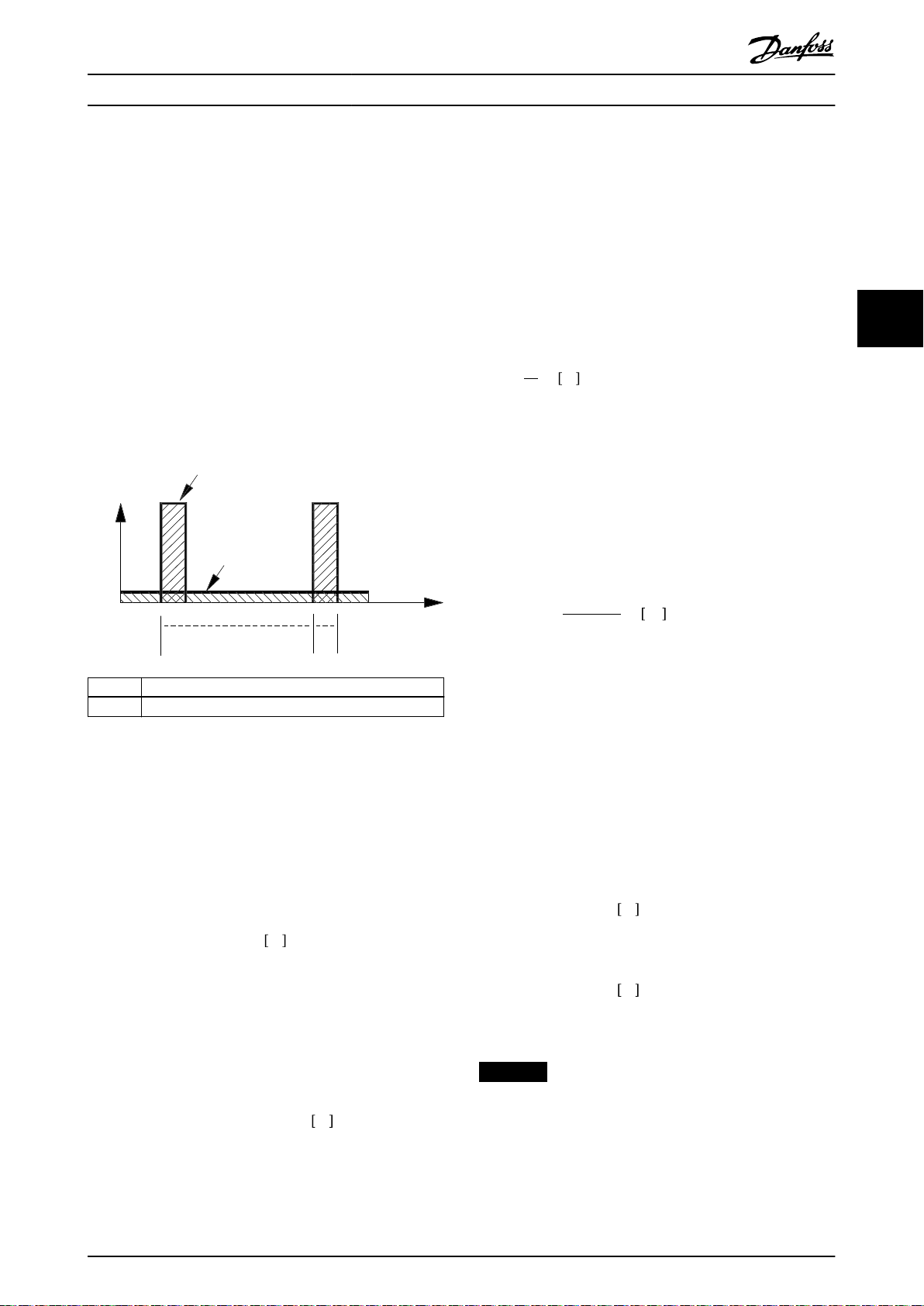
Illustration 2.2 Vertical Loads
The brake resistor range is intended to cover the general
braking requirements for horizontal and vertical brake
applications.
To select the best brake resistor for an application, refer to
chapter 8.1 Selection Flow Chart. The ow chart links to
further information, either selection tables or calculations
of inertia or duty cycle.
The brake resistors in this series are all external
components. Therefore, the brake resistor does not form
an integral part of the frequency converter.
The external brake resistor provides the following
advantages:
The resistor time cycle can be selected as
•
required.
The heat developed during braking can be
•
conveyed beyond the panel cabinet to allow the
energy to be used.
The electronic components do not overheat, even
•
when the brake resistor is overloaded.
Horizontal or Vertical Load
2.2
2.2.1 How to Select
The Danfoss brake resistor range consists of 2 groups:
Brake resistors for horizontal loads (conveyors,
•
trolleys, gantry cranes, and so on), see
Illustration 2.1;
Brake resistors for vertical loads (cranes, hoists,
•
elevators), see Illustration 2.2.
To cater for both the horizontal and vertical ranges, 3
types of brake resistors are available:
Aluminum-housed at-pack brake resistors.
•
Aluminum-housed compact brake resistors.
•
Steel grid brake resistors.
•
Aluminum-housed Brake Resistors
2.3
2.3.1 Aluminum-housed Flat-pack Brake
Resistors
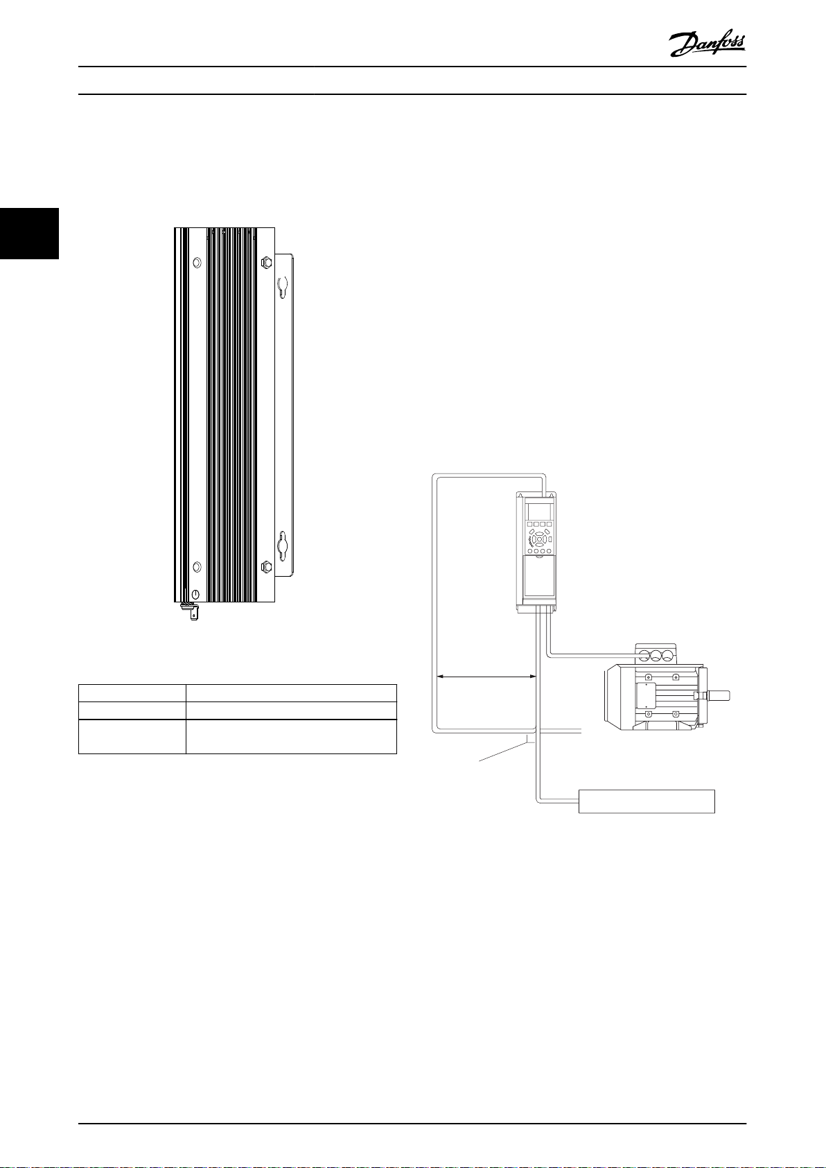
The at-pack brake resistor is an anodized aluminumhoused resistor suitable for wall mounting or on a
footprint or an L-prole bracket. The L-prole bracket is
used for rear mounting. The brake resistor is designed for
high pulse loads of up to 40 times the nominal load and is
therefore suitable for both vertical and horizontal
applications. The enclosure protection is IP54 or IP65.
Illustration 2.3 Flat-pack IP54
Illustration 2.1 Horizontal Loads
MG06H102 Danfoss A/S © 09/2016 All rights reserved. 5
Page 8

130BD646.10
130BD228.10
130BD217.10
130BD586.10
Product Overview
VLT® Brake Resistor MCE 101
2.3.2 Aluminum-housed Compact Brake
2.4 Steel Grid Brake Resistors
Resistor
The steel grid brake resistor is steel grid housed and
22
The compact brake resistor is housed in aluminum proles
with pre-mounted brackets for wall mount. It is designed
for high pulse loads of up to 60 times the nominal load
and is therefore used for both horizontal and vertical loads.
The enclosure protection class is either IP21, IP54, or IP65.
The brake resistor IP classes IP21 and IP65 are equipped
with a connection box containing cable glands and cable
connection to the resistor and the temperature switch.
IP54 versions have xed unshielded cables.
Illustration 2.4 CBR-V-CT IP54
consists of multiple elements. This brake resistor is suitable
for pulse loads between 10 and 20 times the nominal load,
suitable for frequent braking applications such as cranes,
hoists, and elevators. It is supplied in an IP20 enclosure
with cable glands and has a built-in temperature switch.
Illustration 2.5 CBR-V-DT IP21
Illustration 2.7 Steel Grid House IP20
Illustration 2.6 CBR-V-BT IP65
6 Danfoss A/S © 09/2016 All rights reserved. MG06H102
Page 9
130BD900.10
200 mm
Installation Design Guide
3 Installation
3.1 Mechanical Installation
The brake resistors are cooled by natural convection, and
the specied minimum clearances must be observed to
ensure ecient ventilation. The ventilation must be
ecient enough to dispatch the regenerative power in the
brake resistor.
NOTICE
When installing the brake resistor, ensure that all
precautions are in place to avoid the risk of overloading.
Overloading can lead to a re hazard due to the heat
generated in the brake resistor.
The brake resistor is hot during or after braking. The
brake resistor must be located in a secure environment
to avoid re risk.
Mount the brake resistor free of any combustible
•
materials at a well-ventilated location.
The VLT® Brake Resistors MCE 101 brake resistors
•
product type 9xx contain a built-in temperature
switch (for overtemperature protection purposes.
See chapter 3.3 Protective Functions).
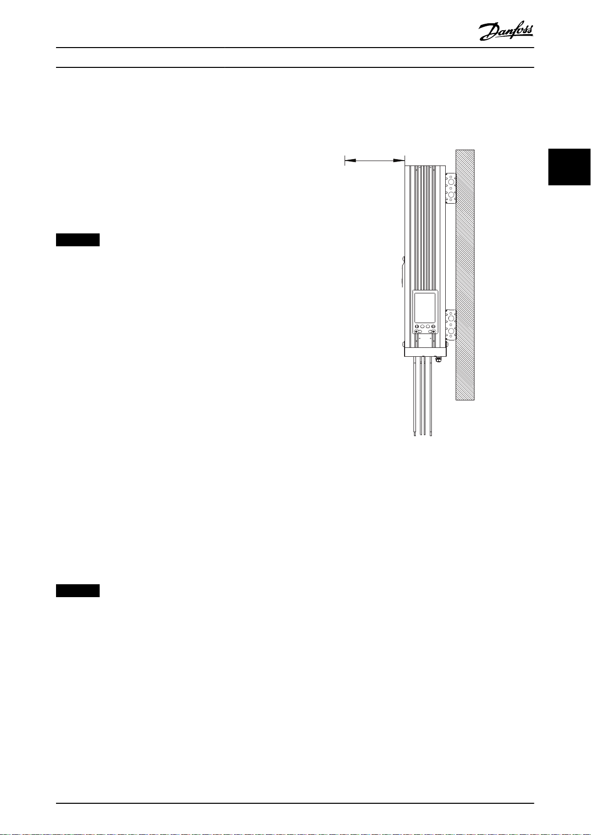
3.1.1 Aluminum-housed Compact Brake
Resistors and Flat-pack Brake Resistors
3 3
Illustration 3.1 Vertical Mounting, IP54
Versions with Fixed Cables
The aluminum-housed compact and at-pack brake
resistors are designed for vertical mounting for optimum
cooling performance. However, horizontal mounting is
possible for both at-pack and compact brake resistors.
Derating with 20% is required when mounting the
compact brake resistors horizontally. No derating for at-
packs are required. The enclosure protection of the IP21
types is reduced to IP20 when mounted horizontally.
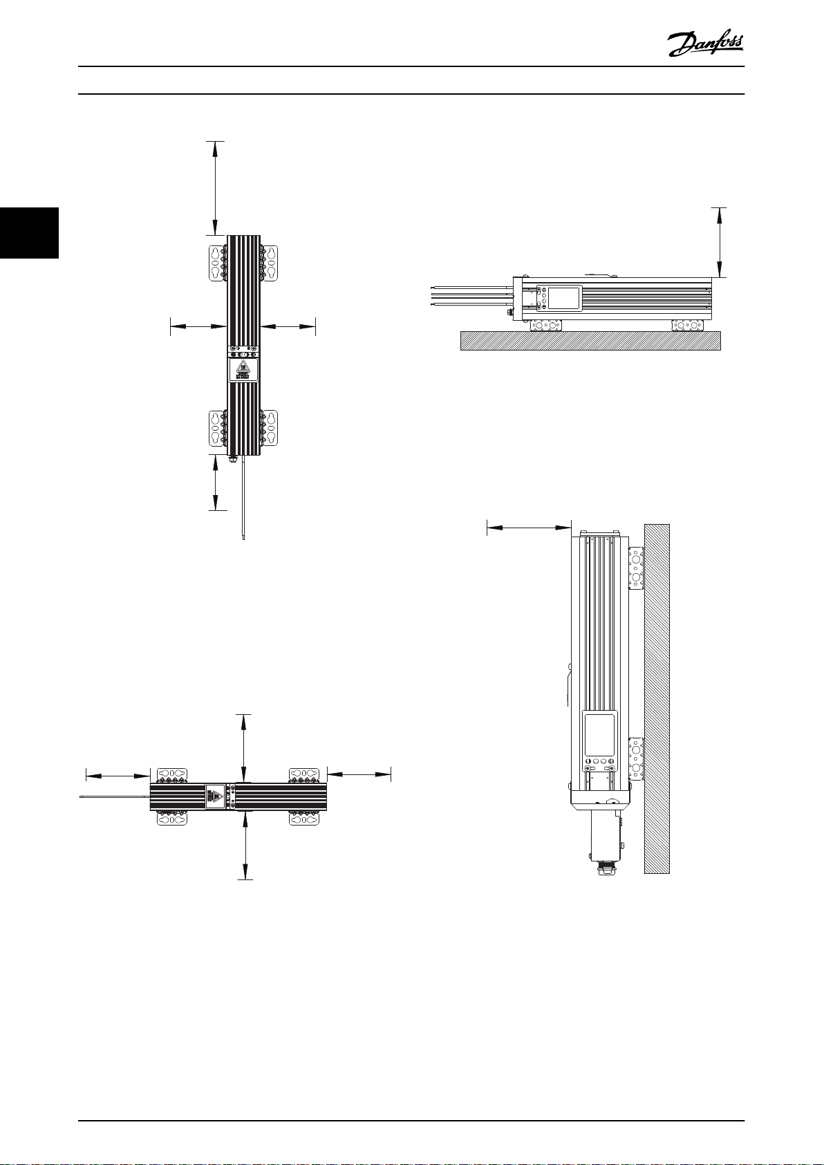
NOTICE
All resistors are cooled by natural convection. To ensure
sucient airow and cooling, follow minimum clearance
in Illustration 3.1 to Illustration 3.8.
Vertical mounting, IP54
For minimum clearances for vertical mounting for all
aluminum-housed compact and at-pack brake resistors,
see Illustration 3.1 and Illustration 3.2.
MG06H102 Danfoss A/S © 09/2016 All rights reserved. 7
Page 10
130BD901.10
200 mm
500 mm
200 mm
200 mm
200 mm
200 mm
200 mm200 mm
130BD902.10
130BD903.10
500 mm
130BD904.10
200 mm
Installation
VLT® Brake Resistor MCE 101
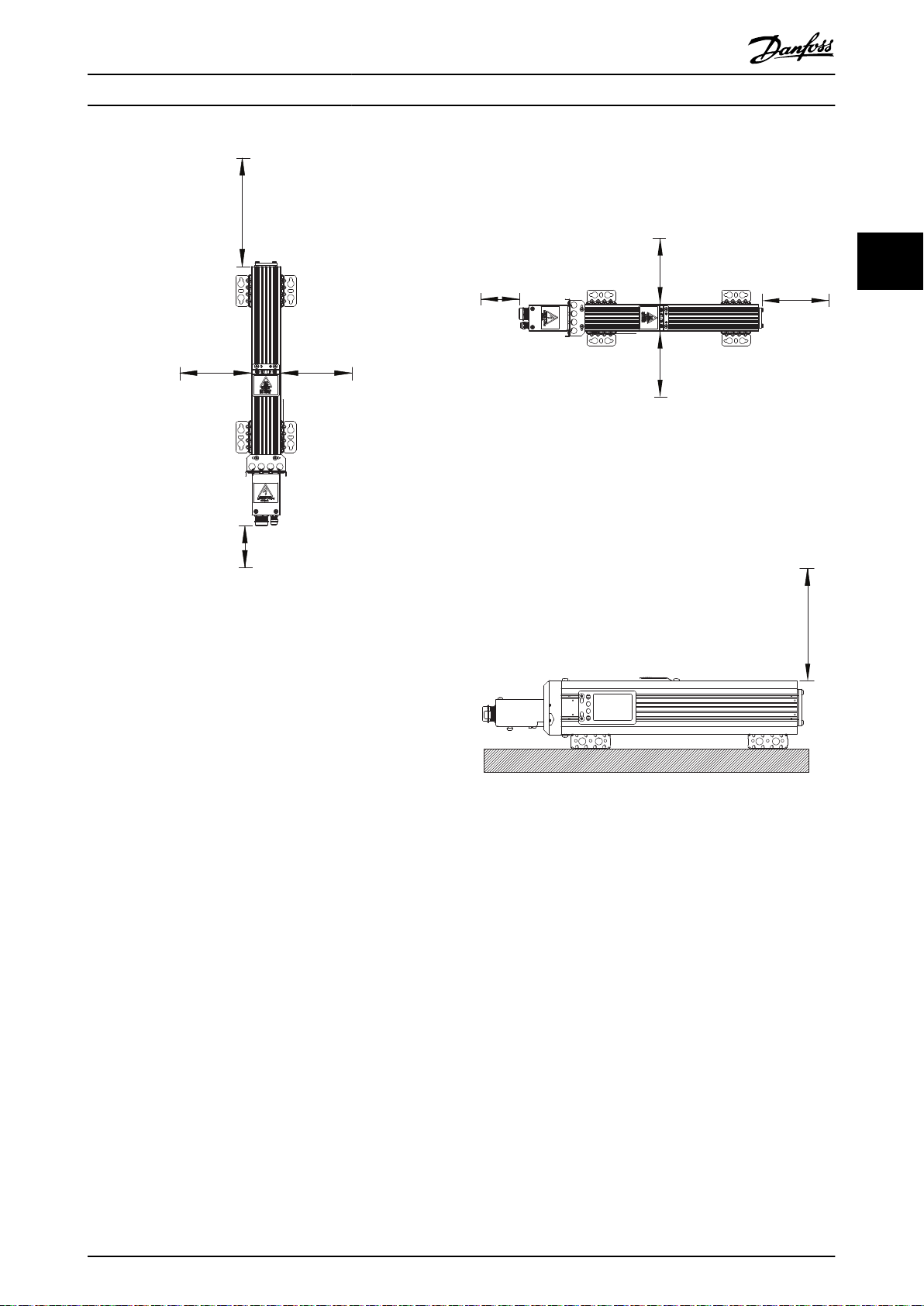
For minimum clearances for horizontal mounting for all
aluminum-housed compact and at-pack brake resistors,
IP54 versions (versions with xed cables), see Illustration 3.4
(side view).
33
Illustration 3.4 Horizontal mounting, IP54
Versions with Fixed Cables
Vertical mounting, IP21 and IP65
For minimum clearances for vertical mounting for all
aluminum-housed compact brake resistors, see
Illustration 3.5 and Illustration 3.6.
Illustration 3.2 Vertical Mounting, IP54
Versions with Fixed Cables
Horizontal mounting, IP54
For minimum clearances for horizontal mounting for all
aluminum-housed compact and at-pack brake resistors,
see Illustration 3.3 (top view).
Illustration 3.3 Horizontal mounting, IP54
Versions with Fixed Cables
Illustration 3.5 Vertical Mounting, IP21 and IP65
Versions with Connection Box
8 Danfoss A/S © 09/2016 All rights reserved. MG06H102
Page 11
200 mm
200 mm
500 mm
100 mm
130BD905.10
200 mm
100 mm
200 mm
200 mm
130BD906.10
130BD907.10
500 mm
Installation Design Guide
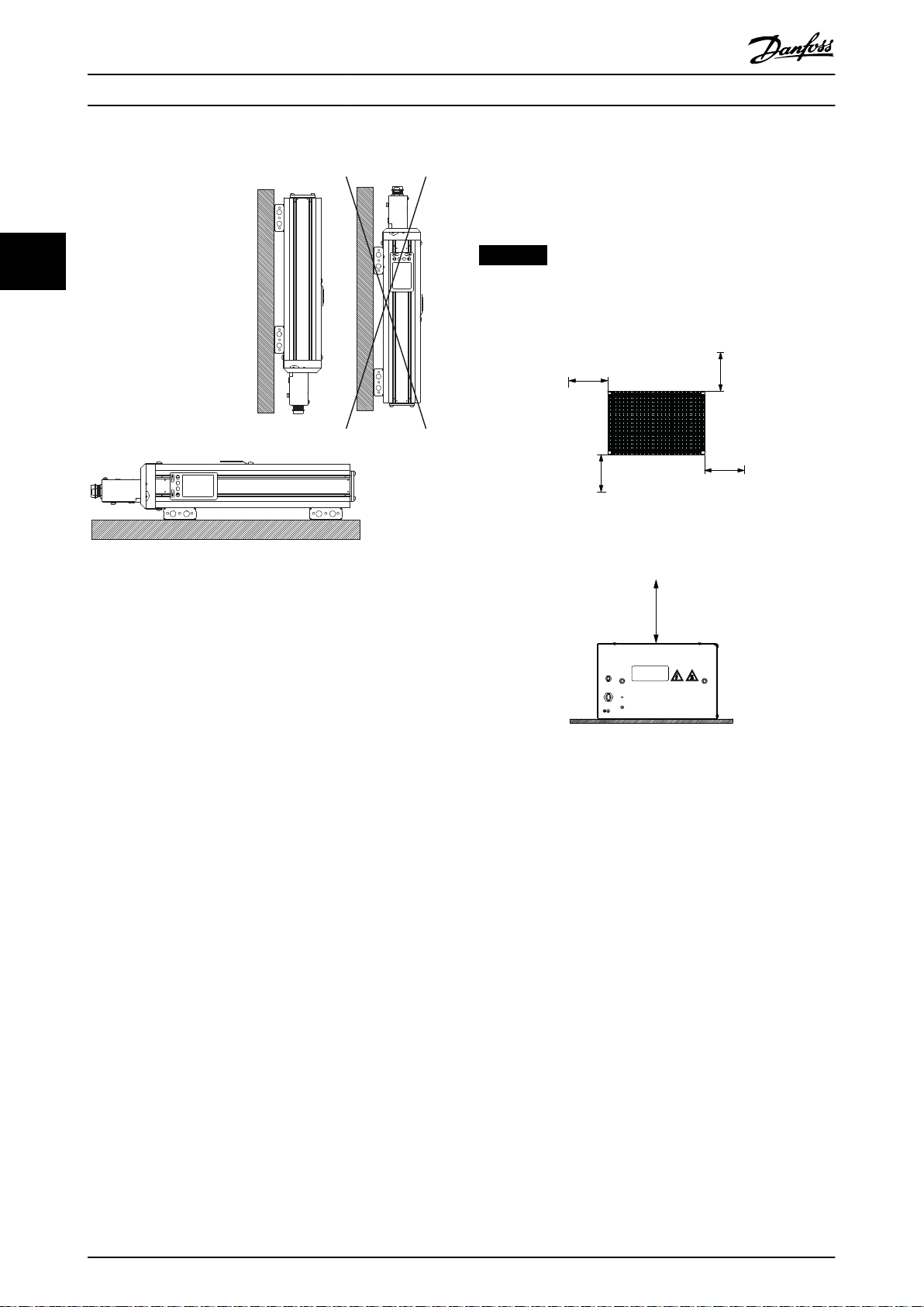
Horizontal mounting, IP21 and IP65
For minimum clearances for horizontal mounting for all
aluminum-housed compact brake resistors, see
Illustration 3.7 (top view).
3 3
Illustration 3.7 Horizontal Mounting, IP21 and IP65
Versions with Connection Box
Horizontal mounting, IP21 and IP65
For minimum clearances for horizontal mounting for all
aluminum housed compact brake resistors, see
Illustration 3.8 (side view).
Illustration 3.6 Vertical Mounting, IP21 and IP65
Versions with Connection Box
Illustration 3.8 Horizontal Mounting, IP21 and IP65
Versions with Connection Box
MG06H102 Danfoss A/S © 09/2016 All rights reserved. 9
Page 12
130BD227.11
130BD708.12
150 mm
150 mm
150 mm
150 mm
500 mm
175Uxxxx
130BD884.10
Installation
VLT® Brake Resistor MCE 101
Orientation, compact and at-pack brake resistors
3.1.2 Steel Grid Brake Resistors
The steel grid brake resistors are designed for horizontal
mounting only.
33
NOTICE
All resistors are cooled by natural convection. To ensure
sucient airow and cooling, follow minimum clearances
in Illustration 3.10 and Table 3.3.
Illustration 3.10 Minimum Clearances of all Steel Grid Brake
Resistors - Top View
Illustration 3.9 Orientation of Compact and Flat-pack Brake
Resistors
Derating with 20% is required when mounting the
compact brake resistors horizontally. The enclosure
protection of the IP21 types is reduced to IP20 when
mounted horizontally.
Illustration 3.11 Minimum Clearances of all Steel Grid Brake
Resistors - Side View
10 Danfoss A/S © 09/2016 All rights reserved. MG06H102
Page 13
175Uxxxx
130BD709.11
1
2
3
130BD595.10
Installation Design Guide
3 3
Illustration 3.12 Orientation of Steel Grid Brake Resistors
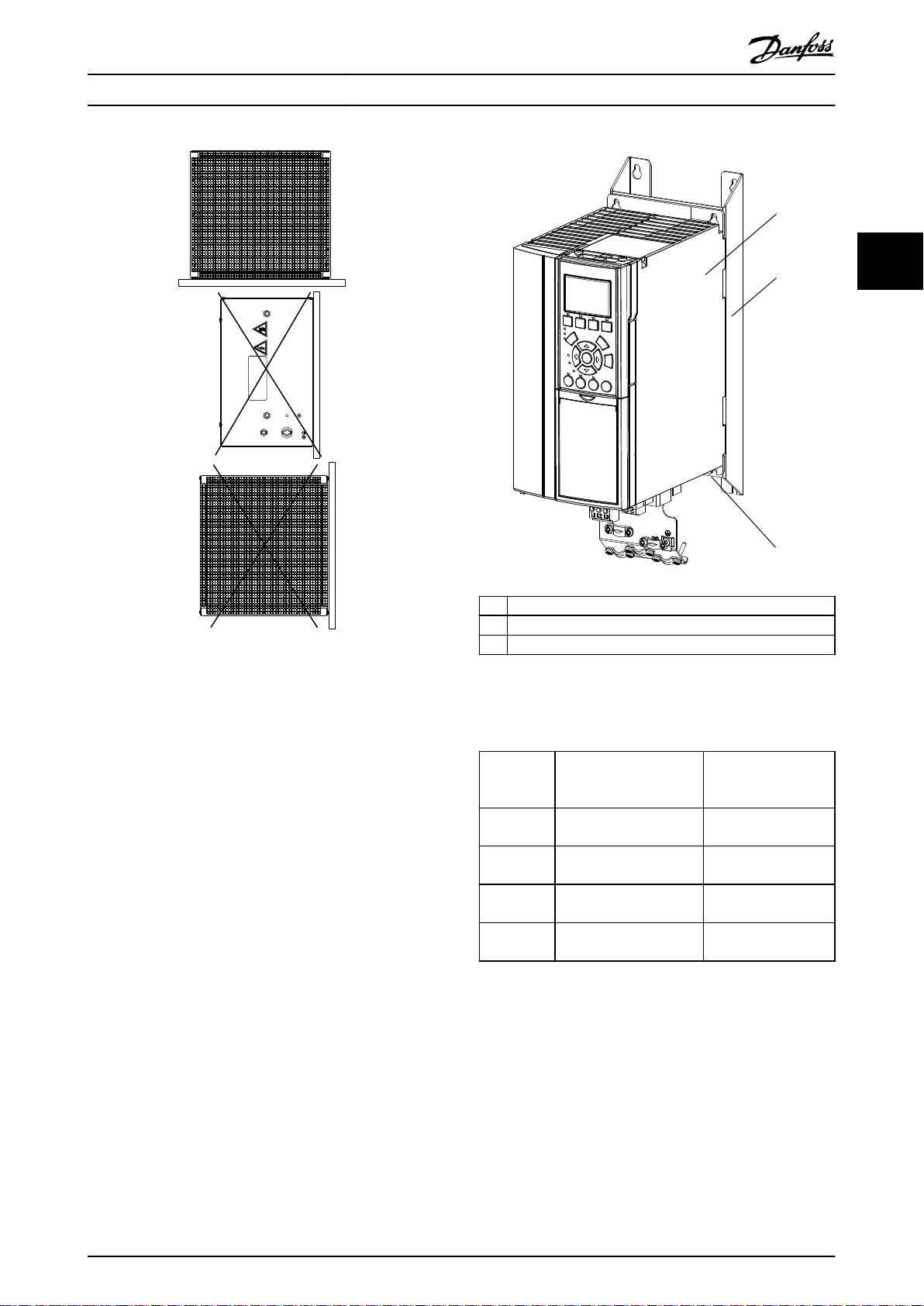
3.1.3 Accessories
Footprint brackets
The footprint bracket is an accessory used for mounting
at-pack brake resistors.
Use the footprint bracket to mount the brake resistor at
the rear of the frequency converter. Once mounted, the
combined brake resistor and frequency converter occupy
the same space in the cabinet as the frequency converter
alone.
1 Frequency converter
2 Footprint mounting bracket
3 Flat-pack brake resistor
Illustration 3.13 Flat-pack Brake Resistor Mounted at Rear of
Frequency Converter
Part number Compatible brake resistor Compatible frequency
converter enclosure
size
175U0085
175U0087
175U0086
175U0088
Table 3.1 Selection Table
1x100 W at-pack
1x200 W at-pack
2x100 W at-pack
2x200 W at-pack
2x100 W at-pack
2x200 W at-pack
1x100 W at-pack
1x200 W at-pack
A2
A2
A3
A3
For mechanical dimensions for footprint brackets, see
chapter 9.8.2 Mounting Brackets: Footprint.
MG06H102 Danfoss A/S © 09/2016 All rights reserved. 11
Page 14
130BD838.10
Fieldbus cable
Min. 200 mm
90° crossing
Brake resistor
130BD507.11
Installation
VLT® Brake Resistor MCE 101
L prole brackets
Electrical Installation
3.2
The L prole bracket is an accessory used for mounting
at-pack brake resistors. The L prole brackets support
3.2.1 EMC Precautions
both horizontally and vertically mounting on a xed
surface optimizing the required footprint.
33
The following EMC precautions are recommended to
achieve interference-free operation of
eldbus cable(s) and
digital and analog inputs and outputs.
Observe relevant national and local regulations, for
example regarding protective earth connection. Keep the
eldbus cable(s) away from motor cables and brake resistor
cables to avoid coupling of high frequency noise from one
cable to another. Normally, a distance of 200 mm (8
inches) is sucient, but keeping the greatest possible
distance between the cables is recommended, especially
where cables run in parallel over long distances. When
crossing is unavoidable, the eldbus cable(s) must cross
motor cables and brake resistor cables at an angle of 90°,
see Illustration 3.15.
Illustration 3.14 L Prole Bracket
Part number Compatible brake resistor
175U0009 1x200 W at-pack
175U0011
Table 3.2
1) Order 2x175U0011 for 300 W at-pack brake resistors.
1)
For mechanical dimensions for L
1x100 W at-pack
1x300 W at-pack
prole brackets, see
chapter 9.8.1 Mounting Brackets: L Prole.
Illustration 3.15 Cable Routing
12 Danfoss A/S © 09/2016 All rights reserved. MG06H102
Page 15
130BB154.12
130BF240.10
(1)
(2)
Installation Design Guide
3.2.2 Cable Connection
NOTICE
To comply with EMC emission specications, shielded/
armored cables are recommended.
NOTICE
Cables general: All cabling must comply with national
and local regulations on cable cross-sections and
ambient temperature.
3 3
See Table 3.3 for recommended temperature ratings for all
cables and conductors connected to the brake resistor as
ground connection, thermal switch, and brake power.
IP class Recommended cables
IP20
IP21
IP54
IP65
Table 3.3 Cable Temperature Ratings
1) For ground connection.
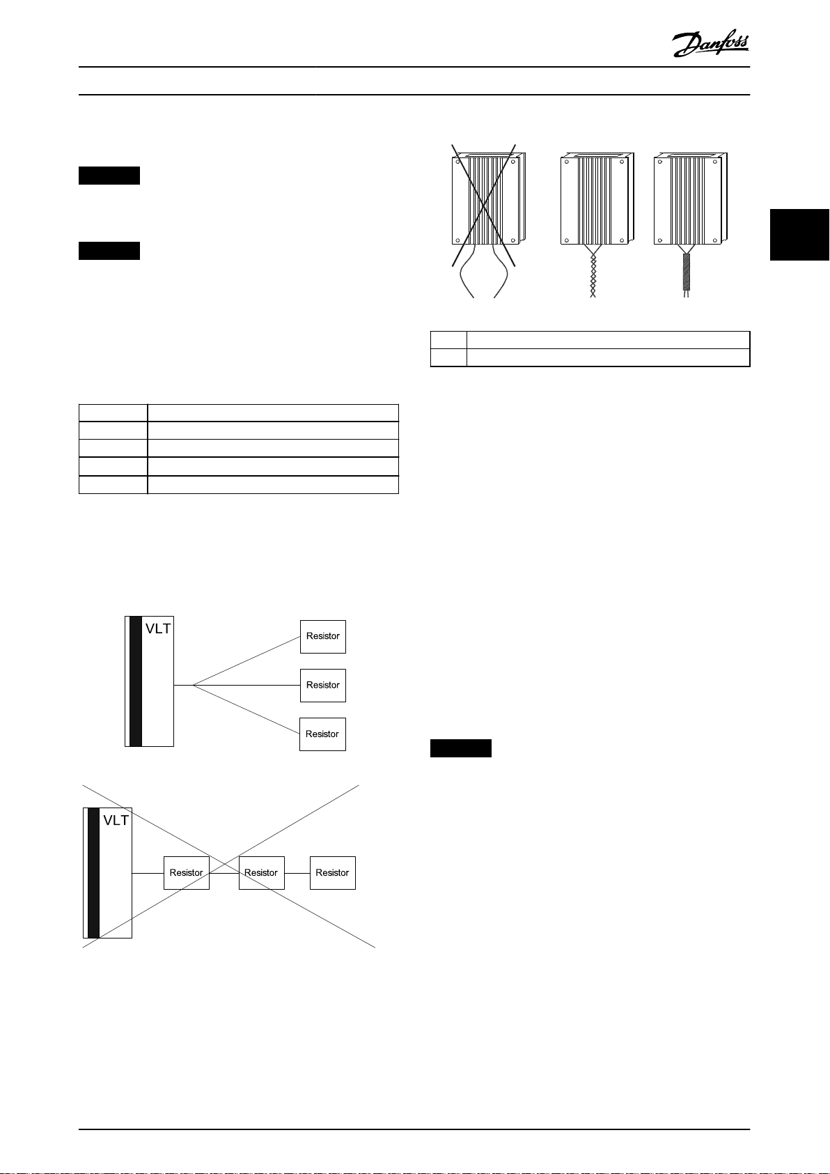
How to connect more than 1 resistor
Star parallel connection to ensure that load is shared
evenly between 2 or more resistors.
≥80 °C (176 °F)
≥80 °C (176 °F)
≥90 °C (194 °F)
≥90 °C (194 °F)
1)
(1) Twisted pair
(2) Shielded cable
Illustration 3.17 Twisted Cables
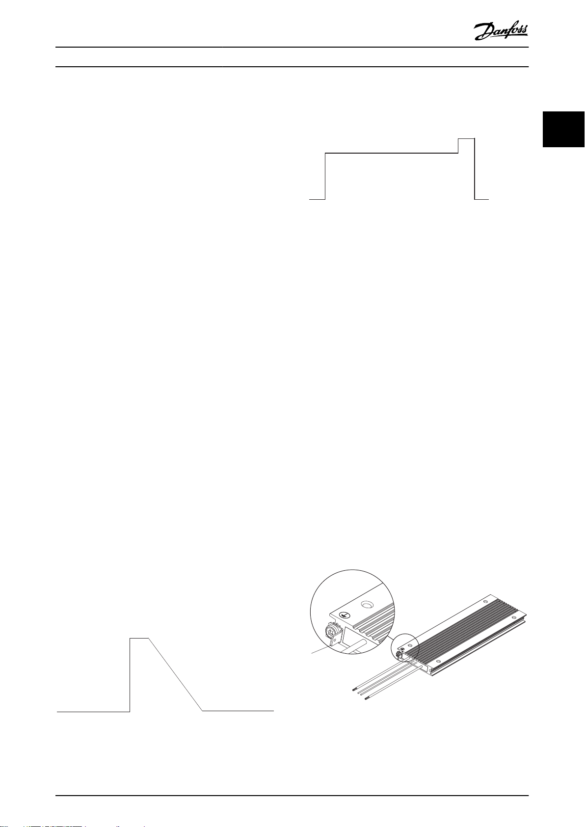
3.2.3 Brake Cable
Maximum length: 20 m (66 ft) shielded cable.
Ensure the connection cable to the brake resistor is
shielded. Connect the shielding to the conductive back
plate of the frequency converter and to the brake resistor
metal cabinet, using cable clamps.
Protective Functions
3.3
3.3.1 Overtemperature Protection
Danfoss VLT® Brake Resistors MCE 101 is equipped with a
galvanic isolated temperature switch (PELV) that is closed
under normal operating conditions and open if the brake
resistor is overheated.
NOTICE
Use the temperature switch as overtemperature
protection feature to prevent damage of the brake
resistor caused by overtemperature. To prevent damage
to the brake resistor, perform an immediate stop or a
ramp down.
There are several ways the temperature switch can be
Illustration 3.16 Connection of Several Brake Resistors
Brake resistors with xed cables
To reduce the electrical noise from the wires between the
brake resistor and the frequency converter, twist the wires.
For enhanced EMC performance, a metal shield can be
used.
MG06H102 Danfoss A/S © 09/2016 All rights reserved. 13
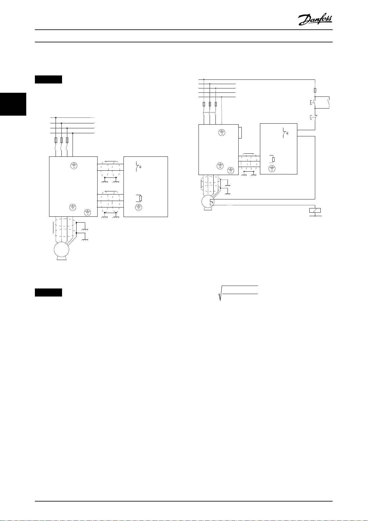
used:
The temperature switch as digital input to frequency
converter
Example 1
1. Connect terminal T1 of the brake resistor to the
frequency converter terminal 12 or 13.
2. Connect terminal T2 of the brake resistor to a
digital input, for example terminal 18.
Automatic restart after enabling of the temperature
switch:
Select coast inverse for the selected digital input.
Page 16
81
82
99
91 92 93 95
96 97 98 99
12
18
L1 L2 L3 PE
U V W PE
VLT
MCE 101
Brake resistor
T1
T2
RB1
RB2
L1
L2
L3
PE
F1
PE
R-
R+
PE
+24V
D-in
M
3~
130BD553.11
91 92 93 95
96 97 98 99
M
3~
12
27
L1 L2 L3 PE
VLT
MCE 101
Brake resistor
T1
T2
RB1
RB2
99
PE
81
R -
82R+
PE
L1
L2
L3
N
PE
F1
S1 K1
F2
S2
K1
K1
U V W PE
130BD554.11
Installation
VLT® Brake Resistor MCE 101
Prevent automatic restart:
Example 2
Select latched start for the selected digital input.
NOTICE
Coast does not terminate the brake function.
33
Example 1
Illustration 3.19 Temperature Switch in both Motor and Brake
Resistor Disabling Mains Supply by an Input Contactor
Illustration 3.18 Temperature Switch in Brake Resistor
NOTICE
The temperature switch as input to the frequency
converter cannot be considered a primary safety
function.
In case of a malfunction in the brake IGBT, the frequency
converter and brake resistor are only protected by
disconnecting the mains supply to the frequency
converter. The temperature switch must be connected
disabling the mains supply to the frequency converter by
a contactor preventing dangerous overtemperatures.
The temperature switch disabling the mains supply to
VLT by a contactor
Example 2
1. Connect the brake resistor built-in thermal switch
as controlling an input contactor. In this example,
the thermal switch within the brake resistor is
connected in series with the thermal switch
within the motor.
2. Connect start and stop push buttons in series
with the thermal switches.
3. Connect to a contactor in the mains supply in
front of the frequency converter.
Thermal overheating in brake resistor or motor disables the
mains supply to the frequency converter.
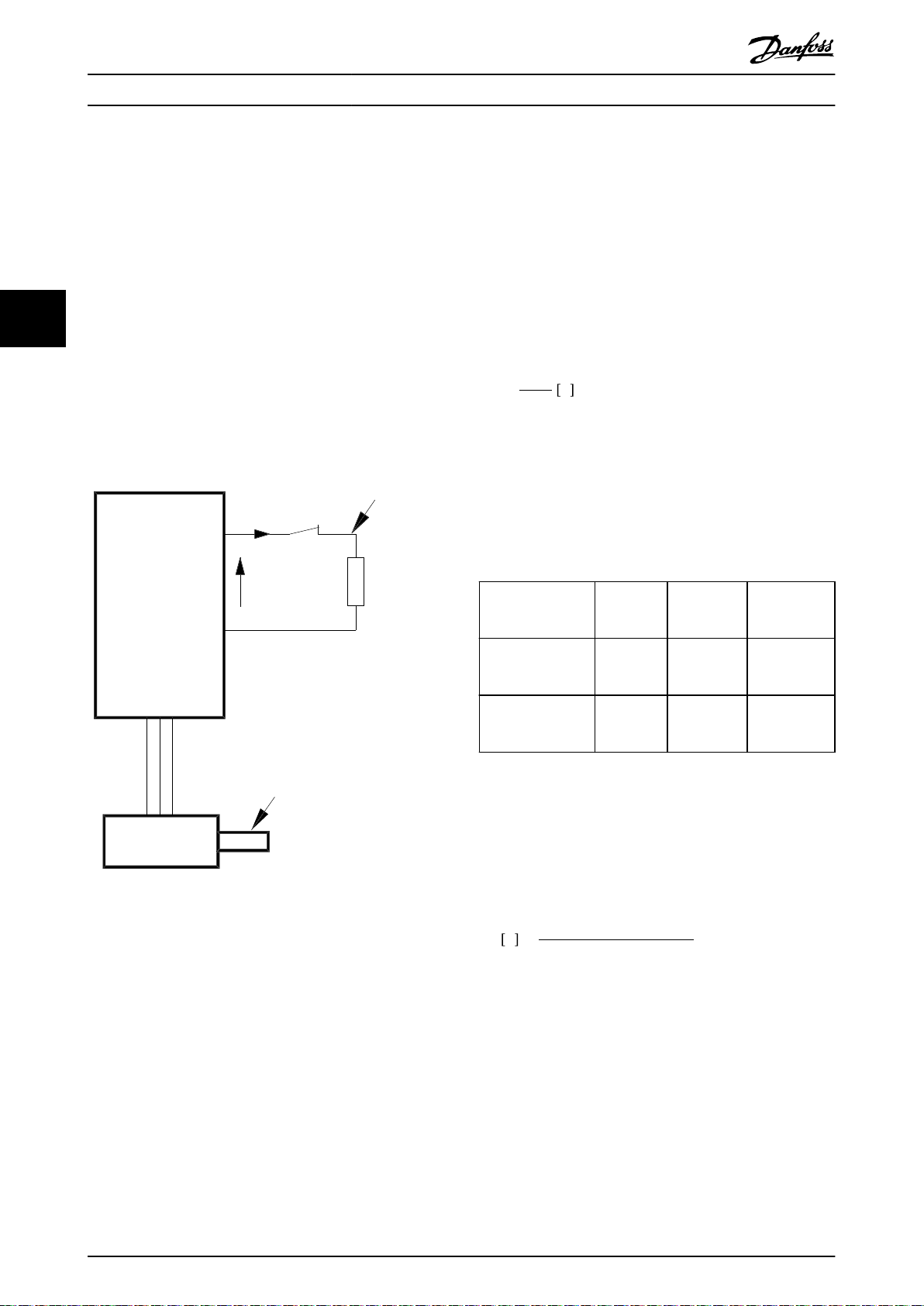
Thermo relay disabling the brake resistor
Example 3
Calculate the brake current (I
thermo relay
) setting of the
temperature switch as follows:
P
I
thermo relay
brake resistor max
=
R
br
Rbr is the current brake resistor value calculated in
chapter 4.1.2 Calculation of Brake Resistor Resistance.
Look up the brake current setting of the thermo relay for
Danfoss brake resistors in chapter 8 Selection Guide.
14 Danfoss A/S © 09/2016 All rights reserved. MG06H102
Page 17

Installation Design Guide
3.3.2 Brake Resistor and Brake IGBT
Brake resistor power monitor
In addition, the brake power monitor function makes it
possible to read out the momentary power and the mean
power for a selected time period. The brake can also
monitor the power energizing and make sure that it does
not exceed a limit selected in parameter 2-12 Brake Power
Limit (kW). In parameter 2-13 Brake Power Monitoring, select
the function to carry out when the power transmitted to
the brake resistor exceeds the limit set in
parameter 2-12 Brake Power Limit (kW).
NOTICE
Monitoring the brake power does not fulll a safety
function. The brake resistor circuit is not ground leakage
protected.
The brake is protected against short-circuiting of the brake
resistor, and the brake transistor is monitored to ensure
that short-circuiting of the transistor is detected. Use a
relay or digital output to protect the brake resistor against
overloading in the event of a fault in the frequency
converter, see chapter 3.3.1 Overtemperature Protection.
3 3
Overvoltage control (OVC) can be selected as an alternative
brake function in parameter 2-17 Over-voltage Control. If the
DC-link voltage increases, this function is active for all
units. The function ensures that a trip can be avoided. This
is done by increasing the output frequency to limit the
voltage from the DC link. It is a useful function, for
example if the ramp-down time is too short since tripping
of the frequency converter is avoided. In this situation, the
ramp-down time is extended.
MG06H102 Danfoss A/S © 09/2016 All rights reserved. 15
Page 18
P
peak,mec.
175ZA096.14
VLT
U
DC
I
termo
P
peak
P
avg
R
br
P
b, max
P
motor
η
INV
= 0.98
η
motor
= 0.9
System Integration
4 System Integration
VLT® Brake Resistor MCE 101
4.1 Brake Resistor Calculation
4.1.2 Calculation of Brake Resistor
Resistance
To ensure the optimal selection of brake resistor for a
given application, its inertia and braking prole
calculations are required.
44
This chapter explains the calculations required to obtain
values for optimal selection of brake resistor for a given
application.
4.1.1 Brake Set-up
The following sections use expressions and abbreviations
related to the brake set-up in Illustration 4.1.
To prevent the frequency converter from cutting out for
protection when the motor brakes, select resistor values on
the basis of the peak braking power and the DC-link
voltage:
Rbr =
Ω
P
peak
2
Udc
The brake resistor performance depends on the DC-link
voltage (Udc).
Udc is the voltage, where the brake is activated. The FCseries brake function is settled depending on the mains
supply.
DC-link voltage (Udc), VLT® AutomationDrive FC 360
Size [V]
FC 360 3x380–480,
0.37–22 kW (0.5–30
hp)
FC 360 3x380–480,
30–75 kW (40–100
hp)
Brake
active
[V DC]
700–770
N/A
1)
2)
Overvoltage
warning
[V DC]
800 800
800 800
Overvoltage
alarm
[V DC]
Illustration 4.1 Brake Set-up
Table 4.1 DC-link Voltage (Udc), FC 360
1) Adjustable with parameter 2-14 Brake voltage reduce
2) No built-in brake option
Use the brake resistance R
, to ensure that the frequency
rec
converter is able to brake at the highest braking torque
(M
) (for example 160%). The formula is written as:
br(%)
R
Ω =
η
η
rec
motor
VLT
P
motor
is typically at 0.90
is typically at 0.98
x M
2
U
dc
br ( % )
x 100
x η
VLT
x η
motor
When a higher brake resistor resistance is selected, 160%/
150%/110% braking torque cannot be obtained, and there
is a risk that the frequency converter cuts out of DC-link
overvoltage for protection.
For braking at lower torque, for example 80% torque, it is
possible to install a brake resistor with lower power rating.
Calculate size using the formula for calculating R
.
rec
16 Danfoss A/S © 09/2016 All rights reserved. MG06H102
Page 19
P
[W]
P
peak
P
avg
T
p
T
b
t [s]
175ZA094.13
System Integration Design Guide
4.1.3 Calculation of Braking Power
When calculating the braking power, ensure that the brake
resistor is scaled for the average power as well as the peak
power.
The average power is determined by the process
•
period time, that is the length of the braking
time in relation to the process period time.
The peak power is determined by the braking
•
torque, which means that as braking progresses,
the brake resistor must be able to dissipate the
energy input.
Illustration 4.2 shows the relation between the average
power and the peak power.
4.1.5 Calculation of the Brake Resistor
Average Power
The average power is determined by the length of the
braking time in relation to the process period time.
When the kinetic energy (Eb) transferred to the resistor in
each braking sequence is known (see chapter 6.1 Conveyor
Belt and chapter 6.2 Centrifuge), calculate the average
power of the brake resistor as follows:
E
b
=
T
p
W
Tb × 100
T
p
%
P
avg
Tp = period time in s, see Illustration 4.2.
When the kinetic energy transferred to the resistor in each
braking sequence is not known, calculate the average
power based on the process period time and the braking
time.
Calculate the duty cycle for the braking sequence as
follows:
Duty cycle =
where
4 4
T
p
T
b
Illustration 4.2 Relation between Average Power and Peak
Power
Process period time in s
Braking time in s
4.1.4 Calculation of the Brake Resistor Peak
Power
P
the motor shaft. Calculate P
P
P
when the motor brakes.
P
the eciencies of the motor and the frequency converter.
Calculate P
P
When the brake resistor recommended by Danfoss is
selected (R
chapter 8 Selection Guide, the brake resistor is certain to
provide a braking torque of 160%/150%/110% on the
motor shaft.
is the peak power by which the motor brakes on
peak, mec
as follows:
peak, mec
= P
peak, mec
is the braking power dissipated to the brake resistor
peak
is lower than P
peak
= P
peak
motor
× M
motor
as follows:
peak
× M
) on the basis of the tables in
rec
W
BR( %)
since the power is reduced by
peak,mec
× η
× η
BR( %)
motor
VLT
W
Tp = process period time in s
Tb = braking time in s
Danfoss oers brake resistors with a duty cycle of
maximum 10% and 40%. If a 10% duty cycle is applied, the
brake resistors are able to absorb P
for 10% of the
peak
period time. The remaining 90% of the period time is used
on deecting excess heat.
Calculate the average power with 10% duty cycle as
follows:
P
avg
= P
× 10 %
peak
W
Calculate the average power with 40% duty cycle as
follows:
P
avg
= P
× 40 %
peak
W
The calculations apply to intermittent braking using a
period time of 30 s.
NOTICE
Exceeding the specied intermittent braking period time
may result in overheating the resistor.
MG06H102 Danfoss A/S © 09/2016 All rights reserved. 17
Page 20
ω Start
ω Stop
∆t
∆ω/∆t
175ZA863.11
System Integration
VLT® Brake Resistor MCE 101
4.1.6 Braking of Inertia
When braking high inertia values on the motor shaft, base
the brake resistor values on the inertia, Δω, Δt, see
Illustration 4.3.
44
Illustration 4.3 Braking of High Inertia
Δt is determined by the ramp-down time.
NOTICE
The ramp-down time goes from the rated motor
frequency to 0 Hz.
P
can be calculated as:
peak
2 × π
60
Δω
Δt
2
Δn
×
Δt
P
P
peak
peak
= η
= η
motor
motor
× η
× η
VLT
VLT
× n
× ω
start
start
j is the motor shaft inertia.
× j ×
× j ×
18 Danfoss A/S © 09/2016 All rights reserved. MG06H102
Page 21
Parameters Design Guide
5 Parameters
For descriptions of all available parameters, see VLT
®
AutomationDrive FC 360 Programming Guide, which is
available from drives.danfoss.com/knowledge-center/
technical-documentation/.
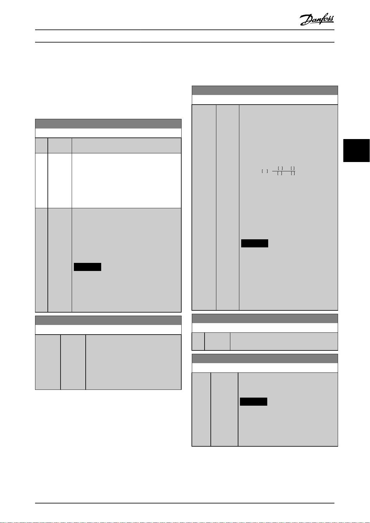
2-10 Brake Function
Option: Function:
[0]*O No brake resistor is installed.
[1] Resistor
brake
[2] AC brake Improve braking without using a brake resistor.
A brake resistor is incorporated in the system for
dissipating surplus brake energy as heat.
Connecting a brake resistor allows a higher DC-
link voltage during braking (generating
operation). The brake resistor function is only
active in frequency converters with an integral
dynamic brake.
This parameter controls an overmagnetization of
the motor when running with a generatoric load.
This function can improve the OVC function.
Increasing the electrical losses in the motor
allows the OVC function to increase braking
torque without exceeding the voltage limit.
NOTICE
The AC brake is not as ecient as
dynamic braking with resistor.
AC brake is for VVC+ mode in both open
and closed loop.
2-12 Brake Power Limit (kW)
Range: Function:
Size
related*
[0.001 -
2000
kW]
Parameter 2-12 Brake Power Limit (kW) is the
expected average power dissipated in the
brake resistor over a period of 120 s. It is
used as the monitoring limit for
parameter 16-33 Brake Energy Average and
species when a warning/alarm is given.
To calculate parameter 2-12 Brake Power
Limit (kW), the following formula can be
used.
P
br, avg
P
is the average power dissipated in
br,avg
the brake resistor. Rbr is the resistance of
the brake resistor. tbr is the active breaking
time within the 120 s period Tbr.
Ubr is the DC voltage where the brake
resistor is active. For T4 units, the DC
voltage is 778 V, which can be reduced by
parameter 2-14 Brake voltage reduce.
NOTICE
If Rbr is not known or if Tbr is dierent
from 120 s, the practical approach is
to run the brake application, read out
parameter 16-33 Brake Energy Average,
and then enter this value + 20% in
parameter 2-12 Brake Power Limit
(kW).
W =
2
U
V × tbrs
br
RbrΩ × Tbrs
5 5
2-11 Brake Resistor (ohm)
Range: Function:
Size
related*
[ 0 -
65535
Ohm]
Set the brake resistor value in Ω. This
value is used for monitoring the power to
the brake resistor. Parameter 2-11 Brake
Resistor (ohm) is only active in frequency
converters with an integral dynamic brake.
Use this parameter for values without
decimals.
2-14 Brake voltage reduce
Range: Function:
0 V* [ 0 - 0 V] Setting this parameter may change the brake
resistor (parameter 2-11 Brake Resistor (ohm)).
2-16 AC Brake, Max current
Range: Function:
100 %* [0 -
160 %]
Enter the maximum allowed current when
using AC brake to avoid overheating of
motor windings.
NOTICE
Parameter 2-16 AC Brake, Max current
has no eect when
parameter 1-10 Motor Construction is
set to [1] PM, non-salient SPM.
MG06H102 Danfoss A/S © 09/2016 All rights reserved. 19
Page 22
Parameters
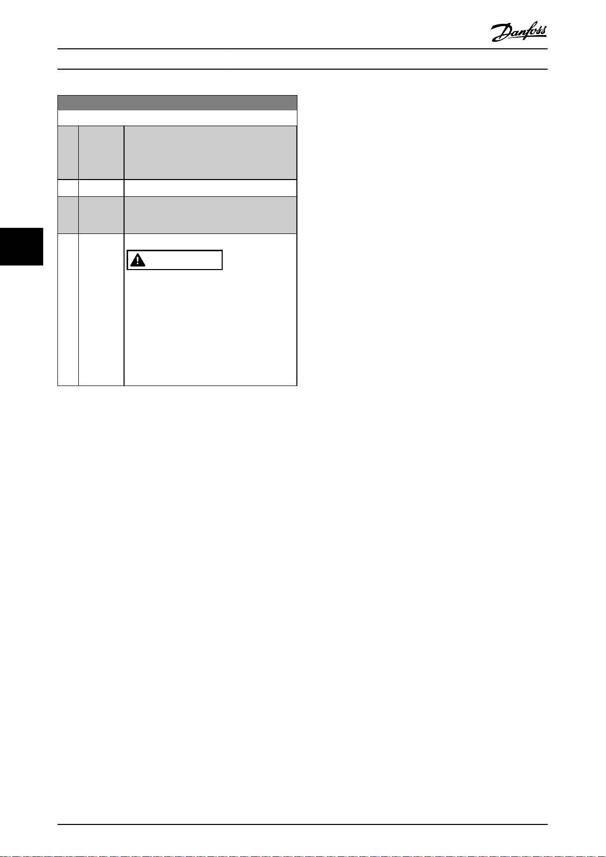
2-17 Over-voltage Control
Option: Function:
Overvoltage control (OVC) reduces the risk of
the frequency converter tripping due to an
overvoltage on the DC link caused by
generative power from the load.
[0] * Disabled No OVC required.
[1] Enabled
(not at
stop)
[2] Enabled Activate OVC.
Activate OVC except when using a stop signal
to stop the frequency converter.
VLT® Brake Resistor MCE 101
55
CAUTION
PERSONAL INJURY AND
EQUIPMENT DAMAGE
Enabling OVC in hoisting applications
may lead to personal injuries and
equipment damage.
DO NOT enable OVC in hoisting
•
applications.
20 Danfoss A/S © 09/2016 All rights reserved. MG06H102
Page 23

Application Examples Design Guide
6 Application Examples
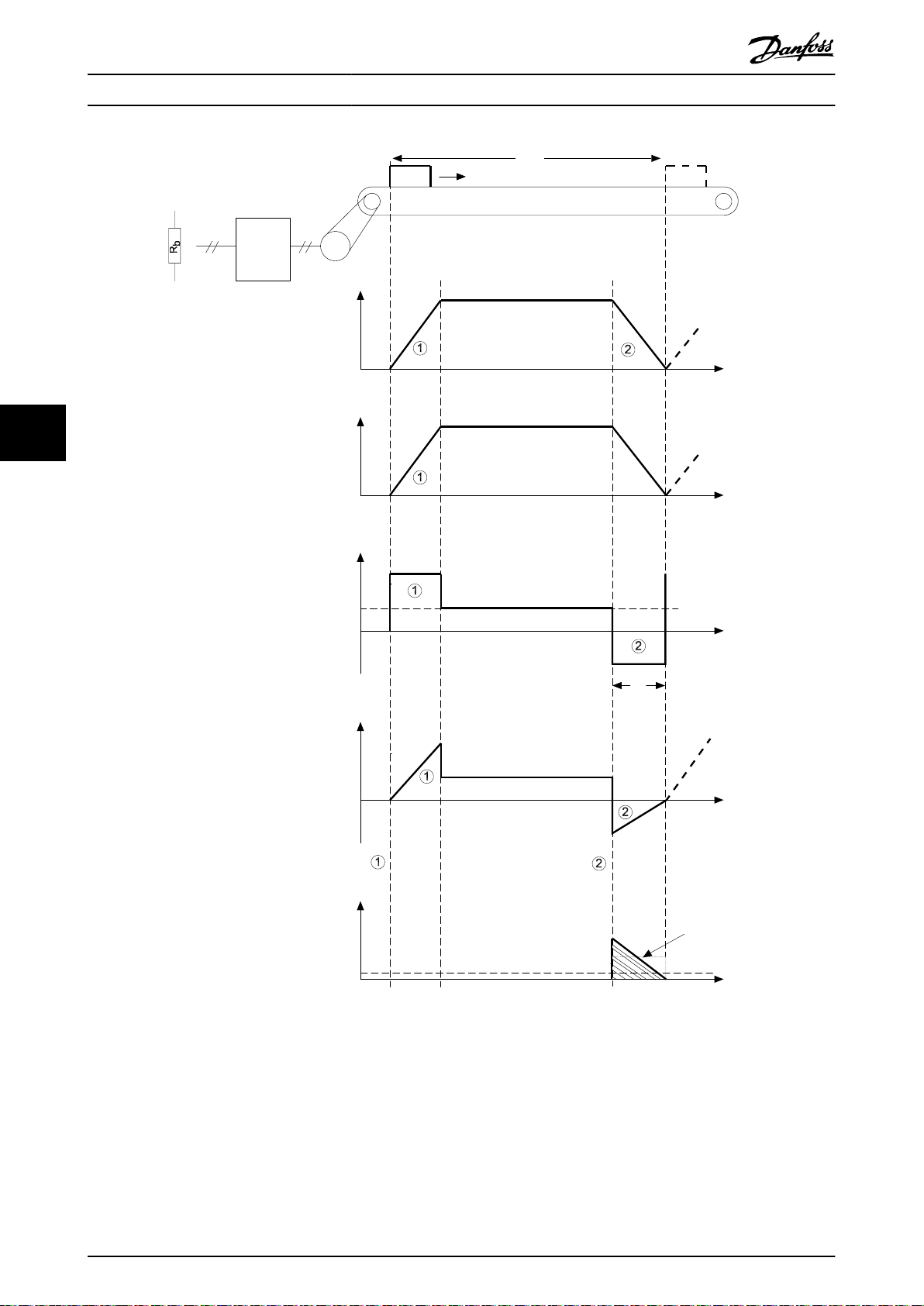
6.1 Conveyor Belt
Illustration 6.1 shows the relation between the braking
power and the acceleration/braking of a conveyor belt.
Note:
The motor power during braking is negative,
•
since the torque on the motor shaft is negative.
The motor power is time-dependent.
•
The braking power (the power to be dissipated to the
brake resistor) corresponds almost exactly to the negative
motor power plus losses in the motor and the frequency
converter.
Kinetic energy (E) in conveyor belt + motor:
E = 0 . 5 × m × v2 + 0 . 5 × j × ω2Ws
where
m = mass with linear movement [kg].
v = speed of mass with linear movement [m/s].
j = inertia of motor and gear box [kgm2].
ω = motor speed [rad/s].
ω = motor speed =
n × 2π
60
rad/ s
This formula is also expressed as follows:
E = 0 . 50 × m × v2 + 0 . 0055 × j × n2Ws
However, not all of the energy is dissipated in the brake
resistor. The friction of the conveyor belt and the power
loss of the motor also contribute to the braking function.
So, the formula for energy dissipation (Eb) to the brake
resistor is as follows:
= 0 . 5 × m v
E
b
where
Mf = Friction torque [Nm].
ŋM = Motor
Insert:
n × 2π
ω =
The result is:
E
60
= 0 . 5 × m v
b
2
+ 0 . 5 jω
2
+ 0 . 0055 × j × n
2
− 0 . 5 × M
eciency.
ω × η
Ws
M
f
2
− 0 . 052 × n × Mf × ηM Ws
6
6
MG06H102 Danfoss A/S © 09/2016 All rights reserved. 21
Page 24
P
average
Time [s]
Time [s]
Time [s]
Time [s]
Length [m]
175ZA397.14
Acceleration
Braking
P
braking, avg.
P
[W]
Motor power
P
[W]
Brake power
M
[Nm]
Torque
V
[m/s]
Speed
VLT®
M
V
[m/s]
Speed
m v
T
p
m
ϖ
[m/s]
T
p
6
Application Examples
VLT® Brake Resistor MCE 101
Illustration 6.1 Conveyor Belt: Relation Between Braking Power and Acceleration/Deceleration
22 Danfoss A/S © 09/2016 All rights reserved. MG06H102
Page 25
Application Examples Design Guide
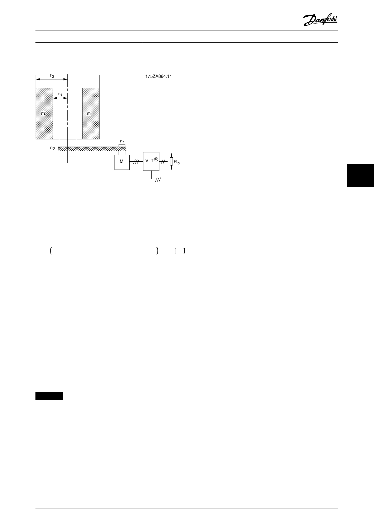
6.2 Centrifuge
Illustration 6.2 Centrifuge with Brake Resistor
Illustration 6.2 shows braking of a centrifuge, which is a
typical application of brake resistors.
The formula for energy dissipation (Eb) to the brake resistor
is:
6
6
Eb = 0 . 0055 × jc × n22 + 0 . 0055 × jM × n12 × ηM Ws
where
m = weight of the centrifuge content [kg].
2
jC = centrifuge inertia [kgm2] = 0.5 x m (r
jM = gear motor inertia [kgm2].
ηM = gear motor
n1 = maximum motor speed [RPM].
n2 = maximum centrifuge speed [RPM].
Rb = brake resistor.
Continuous Braking
6.3
To achieve continuous braking, select a brake resistor in
which the constant braking power does not exceed the
average power P
avg
eciency.
of the brake resistor.
2
+ r
).
1
2
NOTICE
Contact the Danfoss distributor for further information.
MG06H102 Danfoss A/S © 09/2016 All rights reserved. 23
Page 26
175ZA093.10
Special Conditions
7 Special Conditions
VLT® Brake Resistor MCE 101
7.1 Alternative Braking Methods
7.1.1 DC Injection Braking
If the 3-phase winding of the stator is fed with direct
current, a stationary magnetic
stator bore causing a voltage to be induced in the bars of
the cage rotor as long as the rotor is in motion. Since the
electrical resistance of the rotor cage is very low, even
small induced voltages can create a high rotor current. This
current produces a strong braking eect on the bars and
hence on the rotor. As the speed decreases, the frequency
of the induced voltage decreases and with it the inductive
impedance. The ohmic resistance of the rotor gradually
77
becomes dominant and so increases the braking eect as
the speed decreases. The braking torque generated
decreases steeply just before standstill and nally ceases
when there is no further movement. Direct current
injection braking is therefore not suitable for holding a
load at rest.
eld Φ is set up in the
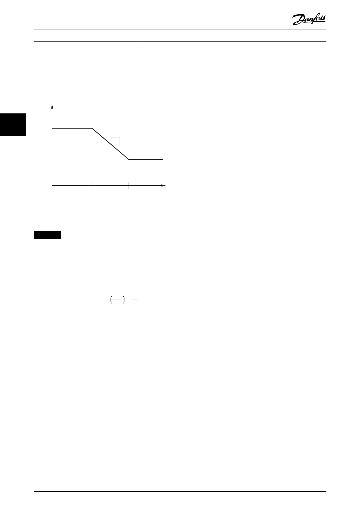
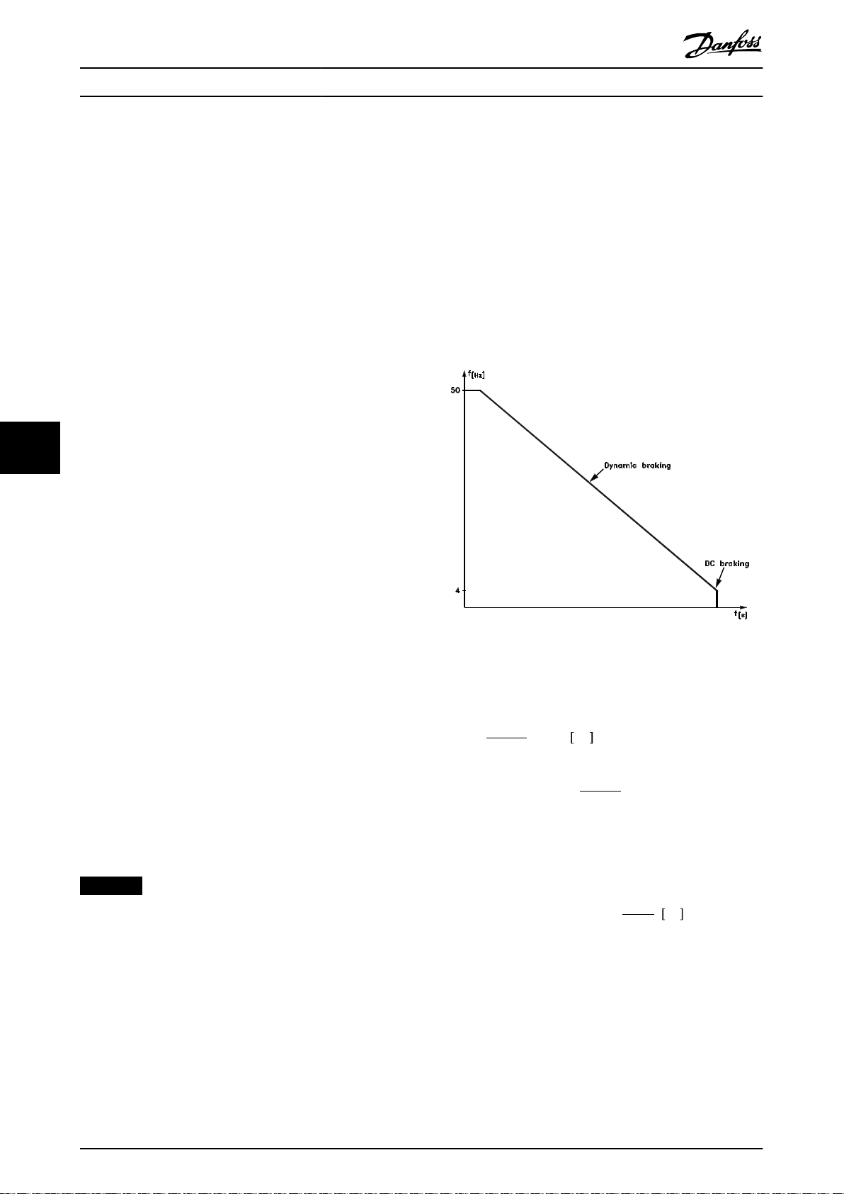
7.1.4 DC Braking
Resistor brake is useful from maximum speed down to a
certain frequency. Below this frequency, DC braking is to
be applied as required. The most ecient way of doing
this is to use a combination of dynamic braking and DC
braking. See Illustration 7.1. The parameters are in
chapter 5 Parameters.
7.1.2 AC-braking
When the motor acts as a brake, the DC-link voltage
increases because energy is fed back to the DC-link. The
principle in AC brake is to increase the magnetization
during the braking and thereby increase the thermal losses
of the motor.
Illustration 7.1 Optimum Braking
How to calculate optimum DC-brake cut in frequency:
7.1.3 Mechanical Holding Brake
n0 − n
n
A mechanical holding brake mounted directly on the
motor shaft normally performs static braking. In some
applications, the static holding torque is working as static
holding of the motor shaft (usually synchronous
permanent motors). A holding brake is either controlled by
a PLC or directly by a digital output from the frequency
converter (relay or solid state).
Slip s =
Synchronous speed n0 =
f = frequency supplied to motor.
p = number of pole pairs.
nn = speed of the rotor.
n
0
× 100
%
f × 60
p
[1/min]
NOTICE
When the holding brake is included in a safety chain:
A frequency converter cannot provide a safe control of a
mechanical brake. A redundancy circuitry for the brake
control must be included in the total installation.
DC-brake cut in frequency = 2 ×
s × f
100
Hz
24 Danfoss A/S © 09/2016 All rights reserved. MG06H102
Page 27
Select a 10%
duty cycle brake
resistor from the
selection tables
Select a 10%
duty cycle brake
resistor from the
selection tables
Select a 40%
duty cycle brake
resistor from the
selection tables
Please contact
Danfoss
1)
Please contact
Danfoss
1)
130BB148.13
Low intertia
ramp down>15 s
Low or high
intertia?
Horizontal
Vertical
Horizontal or
vertical movement?
Determine braking
time of the
application
Braking time<
brake resistor period
Braking time>
brake resistor period
Calculate duty
cycle
duty cycle <10% duty cycle >40%
duty cycle ranging
from 10-40%
High inertia
ramp down<15 s
or don’t know
Compare the braking
time with the resistors
braking period
Selection Guide Design Guide
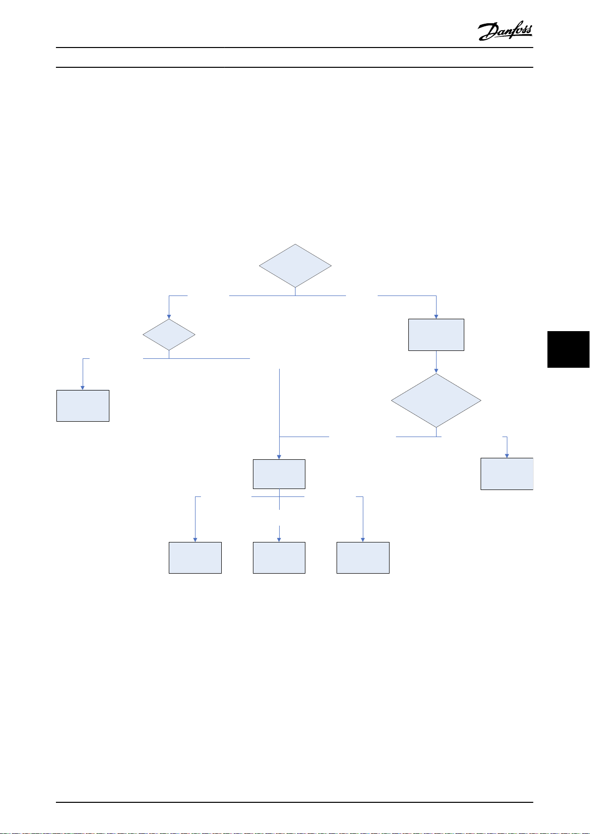
8 Selection Guide
8.1 Selection Flow Chart
To select the correct size of brake resistor for an application, refer to the ow chart in Illustration 8.1.
1. Select an answer to each question from the top down.
2. Follow the answer to reach the next question, or to obtain guidance in calculating inertia or duty cycle.
3. The nal box indicates the correct selection table, or whether to call hotline for additional guidance.
Illustration 8.1 Brake Resistor Selection Flow Chart
1) When contacting Danfoss, provide the following data:
Nominal power 100%
•
Maximum power during brake cycle
•
Braking time/duty cycle
•
Supply voltage (maximum DC)
•
Resistance (Ω)
•
With or without temperature switch
•
IP enclosure rating
•
Type of reference drive
•
8 8
MG06H102 Danfoss A/S © 09/2016 All rights reserved. 25
Page 28
Selection Guide
VLT® Brake Resistor MCE 101
8.2 Selection Tables for Recommended Brake Resistors
8.2.1 Abbreviations used in the Brake Resistor Tables
Mains Voltage class.
P
m
R
min
R
rec
Thermo relay Brake current setting of external thermo relay.
Danfoss part number Danfoss brake resistor order numbers.
Cable cross-section
P
br,cont.
R
br,nom
8.2.2
VLT® AutomationDrive FC 360
10% duty cycle, horizontal braking, T4
88
Frequency converter data
P
m
Mains
type
[kW
(hp)]
T4
T4
T4 0.75 (1) 434 509 630 0.1 (0.13) 175u3002 – – – 1.5 (16) 0.4
T4 1.1 (1.5) 288 338 410 0.1 (0.13) 175u3004 – – – 1.5 (16) 0.5
T4 1.5 (2) 208 244 270 0.2 (0.27) 175u3007 – – – 1.5 (16) 0.8
T4 2.2 (3) 139 164 200 0.2 (0.27) 175u3008 – – – 1.5 (16) 0.9
T4 3 (4) 100 119 145 0.3 (0.4) 175u3300 – – – 1.5 (16) 1.3
T4 4 (5.5) 74.0 87.9 110 0.45 (0.6) 175u3335 175u3450 175u3449 – 1.5 (16) 1.9
T4 5.5 (7.5) 54.0 63.3 80 0.57 (0.76) 175u3336 175u3452 175u3451 – 1.5 (16) 2.5
T4 7.5 (10) 38.0 46.1 56 0.68 (0.91) 175u3337 175u3027 175u3028 – 1.5 (16) 3.3
T4 11 (15) 27.0 33.0 38 1.13 (1.5) 175u3338 175u3034 175u3035 – 1.5 (16) 5.2
T4 15 (20) 19.0 24.0 28 1.4 (1.9) 175u3339 175u3039 175u3040 – 1.5 (16) 6.7
T4 18.5 (25) 16.0 19.4 22 1.7 (2.28) 175u3340 175u3047 175u3048 – 1.5 (16) 8.3
T4 22 (30) 16.0 18.0 19 2.2 (3) 175u3357 175u3049 175u3050 – 1.5 (16) 10.1
T4 30 (40) 11.0 13.8 14 2.8 (3.8) 175u3341 175u3055 175u3056 – 2.5 (14) 13.3
T4 37 (50) 9.0 11.1 12 3.2 (4.3) 175u3359 175u3061 175u3062 – 2.5 (14) 15.3
T4 45 (60) 8.0 9.1 9.5 4.2 (5.6) – 175u3065 175u3066 – 4 (12) 20
T4 55 (75) 6.0 7.4 7.0 5.5 (7.4) – 175u3070 175u3071 – 6 (10) 26
T4 75 (100) 4.0 5.4 5.5 7 (9.4) – – – 175u3231 10 (8) 36
0.37
(0.5)
0.55
(0.75)
Rated motor size for frequency converter.
Minimum allowed brake resistor - by frequency converter.
Recommended brake resistor resistance of Danfoss brake resistors.
Recommended minimum value based upon PVC insulated copper cable. 30 °C (86 °F) ambient temperature with
normal heat dissipation.
Brake resistor average rated power. The temperature switch enables at approximately 90% of continuous rated
power at brake resistors with IP54, IP21, and IP65 enclosure protection.
The nominal (calculated) resistor value to ensure a brake power on motor shaft of 150/160/110% for 1 minute.
FC 360 Horizontal braking 10% duty cycle
Brake resistor data Installation
Danfoss part number Cable
Screw
R
[Ω]
R
min
890 1042 1200 0.1 (0.13) 175u3000 – – – 1.5 (16) 0.3
593 694 850 0.1 (0.13) 175u3001 – – – 1.5 (16) 0.4
br,nom
[Ω]
R
[Ω]
rec
P
br,cont.
[kW (hp)]
Wire IP54
terminal
terminal
IP21
Screw
terminal
IP65
Bolt
connection
IP20
cross-
section
[mm
(AWG)]
Thermo
2
relay
[A]
Table 8.1 T4, Horizontal Braking 10% Duty Cycle
26 Danfoss A/S © 09/2016 All rights reserved. MG06H102
Page 29
Selection Guide Design Guide
40% duty cycle, vertical braking, T4
FC 360 Vertical braking 40% duty cycle
Frequency converter data
P
m
Mains
type
T4
T4
[kW
(hp)]
0.37
(0.5)
0.55
(0.75)
R
[Ω]
min
R
[Ω]
br,nom
R
[Ω]
rec
P
br,cont.
[kW (hp)]
890 1042 1200 0.2 (0.27) 175u3101 – – – 1.5 (16) 0.4
593 694 850 0.2 (0.27) 175u3308 – – – 1.5 (16) 0.5
T4 0.75 (1) 434 509 630 0.2 (0.27) 175u3309 – – – 1.5 (16) 0.7
T4 1.1 (1.5) 288 338 410 0.45 (0.6) 175u3310 175u3416 175u3415 – 1.5 (16) 1
T4 1.5 (2) 208 244 270 0.57 (0.76) 175u3311 175u3418 175u3417 – 1.5 (16) 1.4
T4 2.2 (3) 139 164 200 0.96 (1.29) 175u3312 175u3420 175u3419 – 1.5 (16) 2.1
T4 3 (4) 100 119 145 1.13 (1.5) 175u3313 175u3422 175u3421 – 1.5 (16) 2.7
T4 4 (5.5) 74.0 87.9 110 1.7 (2.3) 175u3314 175u3424 175u3423 – 1.5 (16) 3.7
T4 5.5 (7.5) 54.0 63.3 80 2.2 (3) 175u3315 175u3138 175u3139 – 1.5 (16) 5
T4 7.5 (10) 38.0 46.1 56 3.2 (4.3) 175u3316 175u3428 175u3427 – 1.5 (16) 7.1
T4 11 (15) 27.0 33.0 38 5 (6.7) – – – 175u3236 1.5 (16) 11.5
T4 15 (20) 19.0 24.0 28 6 (8) – – – 175u3237 2.5 (14) 14.7
T4 18.5 (25) 16.0 19.4 22 8 (10.7) – – – 175u3238 4 (12) 19
T4 22 (30) 16.0 18.0 19 10 (13.4) – – – 175u3203 4 (12) 23
T4 30 (40) 11.0 13.8 14 14 (19) – – – 175u3206 10 (8) 32
T4 37 (50) 9.0 11.1 12 17 (23) – – – 175u3210 10 (8) 38
T4 45 (60) 8.0 9.1 9.5 21 (28) – – – 175u3213 16 (6) 47
T4 55 (75) 6.0 7.4 7.0 26 (35) – – – 175u3216 25 (4) 61
T4 75 (100) 4.0 5.4 5.5 36 (48) – – – 175u3219 35 (2) 81
Brake resistor data Installation
Danfoss part number Cable
cross-
section
[mm
(AWG)]
2
Wire IP54
Screw
terminal
terminal
IP21
Screw
terminal
IP65
Bolt
connection
IP20
Thermo
relay
[A]
8 8
Table 8.2 T4, Vertical Braking 40% Duty Cycle
MG06H102 Danfoss A/S © 09/2016 All rights reserved. 27
Page 30

Specications
VLT® Brake Resistor MCE 101
9 Specications
9.1 Ambient Conditions
Environment
Ambient temperature range -40 to 70 °C (-40 to 158 °F)
Temperature range during storage/transport -40 to 70 °C (-40 to 158 °F)
Maximum temperature at housing 300 °C (572 °F)
Maximum relative humidity 5–85%, non-condensation during operation
Power derating as a function of ambient temperature. (100% power rating and pulse-load):
- Steel grid brake resistors, IP20 Continuous power 100% @ 40 °C (104 °F) to 70% @ 70 °C (158 °F), linear
- Aluminum-housed compact brake resistors,
IP21 Continuous power 100% @ 40 °C (104 °F) to 75% @ 70 °C (158 °F), linear
- Aluminum-housed brake resistors - compact
and at-pack, IP54 Continuous power 100% @ 40 °C (104 °F) to 75% @ 70 °C (158 °F), linear
- Aluminum compact brake resistors, IP65 Continuous power 100% @ 40 °C (104 °F) to 50% @ 70 °C (158 °F), linear
Power derating at vertical mounted resistor (wall-mounted) when mounted horizontal (100% power rating and pulseload):
- Aluminum-housed at-pack brake resistors, IP54 No derating
- Aluminum-housed compact brake resistors, IP21, IP54, IP65 -20%
Cooling requirements:
The brake resistors are cooled by free natural convection. The power ratings of the resistors refers to cooling conditions
99
with free natural cooling. The requirements for minimum clearances must be observed during installation.
Derating at high altitudes 100% @ 1000 m (3281 ft) above sea level
Derating at high altitudes 94% @ 1500 m (4921 ft) above sea level
Derating at high altitudes 82% @ 3000 m (9843 ft) above sea level
9.2 General Electrical Specications
Electrical specications
Resistance tolerances ±10%
Insulation >20 MΩ @ 1000 V
Dielectric strength 2500 V AC for 1 minute
Operating voltage:
- Aluminum-housed compact brake resistors, IP54 UL: 600 V AC/600 V DC
- Aluminum-housed compact brake resistors, IP54 IEC: 690 V AC/1100 V DC
- Aluminum-housed at-pack brake resistors, IP54 UL: 1000 V AC/1400 V DC
- Aluminum-housed at-pack brake resistors, IP54 IEC: 1000 V AC/1400 V DC
- Aluminum-housed compact brake resistors, IP21, IP65 UL: 600 V AC/600 V DC
- Aluminum-housed compact brake resistors, IP21, IP65 IEC: 690 V AC/1100 V DC
- Steel grid brake resistors, IP20 IEC: 690 V AC/1100 V DC
Power rating (continuous load 100%) with and without temperature switch
- Without temperature switch 100% of continuous power rating @ 40 °C (104 °F)
- With temperature switch, steel grid brake resistors, IP20 100% of continuous power rating @ 40 °C (104 °F)
- With temperature switch, aluminum-housed brake resistors,
IP21, IP54, IP65 Minimum 80% of continuous power rating @ 40 °C (104 °F)
- With temperature switch, aluminum-housed brake
resistors, IP21, IP54, IP65
Electrical data temperature switch:
- Steel grid brake resistors, IP20 10 A, 250 V AC, normally closed (NC). Enables at 260 °C (500 °F)
- Aluminum-housed brake resistors, IP21, IP54, IP65 2 A, 250 V AC, normally closed (NC). Enables at 180 °C (356 °F)
Temperature switch enables at ≥80% of the continuous power rating
@ 40 °C (104 °F)
28 Danfoss A/S © 09/2016 All rights reserved. MG06H102
Page 31

Specications Design Guide
9.3 Electrical Data: MCE 101 Product Types 9xx
Pulse
load
power
10%
duty
cycle
10.8
(14.5)
17.8
(23.9)
17.8
(23.9)
21.1
(28.3)
21.1
(28.3)
15.6
(20.9)
14.5
(19.4)
21.1
(28.3)
21.1
(28.3)
[Ω]
Continuous
power 100%
load
[W] [kW (hp)] [kW (hp)] Type
P/N
175U3000 1200 100 1.65 (2.2)
175U3001 850 100 1.65 (2.2)
175U3002 630 100 1.65 (2.2)
175U3003 570 100 1.65 (2.2)
175U3004 410 100 1.65 (2.2)
175U3005 415 200 3.05 (4) 0.75 (1) 1 – – – – 0.5 20 1.5 16
175U3006 300 100 1.65 (2.2)
175U3007 270 200 3.05 (4) 0.75 (1) 1 – – – – 0.5 20 1.5 16
175U3008 200 200 3.05 (4) 0.75 (1) 1 – – – – 0.5 20 1.5 16
175U3009 200 360 4.2 (5.6) 1.05 (1.4) 1 4.0 12 16 6 – – – –
175U3010 200 360 4.2 (5.6) 1.05 (1.4) 1 4.0 12 16 6 – – – –
175U3011 200 100 1.65 (2.2)
175U3012 145 450 5 (6.7) 1.25 (1.7) 1 4.0 12 16 6 – – – –
175U3013 145 450 5 (6.7) 1.25 (1.7) 1 4.0 12 16 6 – – – –
175U3014 145 280 2.8 (3.8) 0.7 (0.9) 1 4.0 12 16 6 – – – –
175U3015 145 280 2.8 (3.8) 0.7 (0.9) 1 4.0 12 16 6 – – – –
175U3016 145 100 1.65 (2.2)
175U3017 110 360 4.2 (5.6) 1.05 (1.4) 1 4.0 12 16 6 – – – –
175U3018 110 360 4.2 (5.6) 1.05 (1.4) 1 4.0 12 16 6 – – – –
175U3019 105 570 6.6 (8.9) 1.65 (2.2) 1 4.0 12 16 6 – – – –
175U3020 105 570 6.6 (8.9) 1.65 (2.2) 1 4.0 12 16 6 – – – –
175U3021 100 100 1.65 (2.2)
175U3022 80 450 5 (6.7) 1.25 (1.7) 1 4.0 12 16 6 – – – –
175U3023 80 450 5 (6.7) 1.25 (1.7) 1 4.0 12 16 6 – – – –
175U3024 72 960
175U3025 72 960 13 (17.4) 3.3 (4.4) 1 4.0 12 16 6 – – – –
175U3026 70 200 3.05 (4) 0.75 (1) 1 – – – – 0.5 20 1.5 16
175U3027 56 680 9.4 (12.6) 2.2 (3) 1 4.0 12 16 6 – – – –
175U3028 56 680 9.4 (12.6) 2.2 (3) 1 4.0 12 16 6 – – – –
175U3029 52 1290
175U3030 52 1290
175U3031 48 200 3.05 (4) 0.75 (1) 1 – – – – 0.5 20 1.5 16
175U3032 42 1700
175U3033 42 1700
175U3034 38 1130
175U3035 38 1130
175U3036 35 200 3.05 (4) 0.75 (1) 1 – – – – 0.5 20 1.5 16
175U3037 31 1700
175U3038 31 1700
Resi-
stance
Temp. switch Power cables Temp. switch Power cables
Pulse
load
power
40%
duty
1)
cycle
0.405
(0.54)
0.405
(0.54)
0.405
(0.54)
0.405
(0.54)
0.405
(0.54)
0.405
(0.54)
0.405
(0.54)
0.405
(0.54)
0.405
(0.54)
2.6 (3.5) 1 4.0 12 16 6 – – – –
3.8 (5.1) 1 4.0 12 16 6 – – – –
3.8 (5.1) 1 4.0 12 16 6 – – – –
5.27 (7.1) 1 4.0 12 16 6 – – – –
5.27 (7.1) 1 4.0 12 16 6 – – – –
3.3 (4.4) 1 4.0 12 16 6 – – – –
3.6 (4.8) 1 4.0 12 16 6 – – – –
5.27 (7.1) 1 4.0 12 16 6 – – – –
5.27 (7.1) 1 4.0 12 16 6 – – – –
Temp.
switch
2) 3)
1)
1 – – – – 0.5 20 1.5 16
1 – – – – 0.5 20 1.5 16
1 – – – – 0.5 20 1.5 16
1 – – – – 0.5 20 1.5 16
1 – – – – 0.5 20 1.5 16
1 – – – – 0.5 20 1.5 16
1 – – – – 0.5 20 1.5 16
1 – – – – 0.5 20 1.5 16
1 – – – – 0.5 20 1.5 16
Terminal maximum wire
cross-section
[mm2]
[AWG]
[mm2]
[AWG]
Wire cross-section
[AWG]
[mm2]
[mm2]
4)
[AWG]
9 9
MG06H102 Danfoss A/S © 09/2016 All rights reserved. 29
Page 32

Specications
VLT® Brake Resistor MCE 101
Pulse
load
power
10%
duty
cycle
17.5
(23.5)
17.5
(23.5)
27.3
(36.6)
27.3
(36.6)
21.1
(28.3)
21.1
(28.3)
27.3
(36.6)
27.3
(36.6)
43.4
(58.2)
43.4
(58.2)
52.5
(70.4)
52.5
(70.4)
39.9
(53.5)
39.9
(53.5)
52.5
(70.4)
52.5
(70.4)
14.5
(19.4)
14.5
(19.4)
17.5
(23.5)
17.5
(23.5)
[Ω]
Continuous
power 100%
load
[W] [kW (hp)] [kW (hp)] Type
P/N
175U3039 28 1400
175U3040 28 1400
175U3041 27 280 2.8 (3.8) 0.7 (0.9) 1 4.0 12 16 6 – – – –
175U3042 27 280 2.8 (3.8) 0.7 (0.9) 1 4.0 12 16 6 – – – –
175U3043 27 2200
175U3044 27 2200
175U3047 22 1700
175U3048 22 1700
175U3049 19 2200
175U3050 19 2200
175U3051 15.5 3500
175U3052 15.5 3500
Resi-
stance
Temp. switch Power cables Temp. switch Power cables
99
175U3053 18 450 6.2 (8.3)
175U3054 18 450 6.2 (8.3)
175U3055 14 2800 35 (46.9) 8.7 (11.7) 1 4.0 12 16 6 – – – –
175U3056 14 2800 35 (46.9) 8.7 (11.7) 1 4.0 12 16 6 – – – –
175U3057 13.5 4200
175U3058 13.5 4200
175U3059 13 680 9.4 (12.6) 2.2 (3) 1 4.0 12 16 6 – – – –
175U3060 13 680 9.4 (12.6) 2.2 (3) 1 4.0 12 16 6 – – – –
175U3061 12 3200
175U3062 12 3200
175U3063 11 5500 68.6 (92) 17 (22.8) 1 4.0 12 55 1/0 – – – –
175U3064 11 5500 68.6 (92) 17 (22.8) 1 4.0 12 55 1/0 – – – –
175U3065 9.5 4200
175U3066 9.5 4200
175U3067 9.1 9000 121 (162) 29 (38.9) 2 2.5 14 2xM8 – – – –
175U3068 9.0 1130
175U3069 9.0 1130
175U3070 7.0 5500 68.6 (92) 17 (22.8) 1 4.0 12 55 1/0 – – – –
175U3071 7.0 5500 68.6 (92) 17 (22.8) 1 4.0 12 55 1/0 – – – –
175U3072 7.4 11000 148 (198) 36 (48.3) 2 2.5 14 2xM8 – – – –
175U3073 5.7 1400
175U3074 5.7 1400
175U3075 6.1 13000 174 (233) 42 (56.3) 2 2.5 14 2xM8 – – – –
175U3076 5.5 6300 87 (116.7)
Pulse
load
power
40%
duty
1)
cycle
4.38 (5.9) 1 4.0 12 16 6 – – – –
4.38 (5.9) 1 4.0 12 16 6 – – – –
6.8 (9.1) 1 4.0 12 16 6 – – – –
6.8 (9.1) 1 4.0 12 16 6 – – – –
5.27 (7.1) 1 4.0 12 16 6 – – – –
5.27 (7.1) 1 4.0 12 16 6 – – – –
6.8 (9.1) 1 4.0 12 16 6 – – – –
6.8 (9.1) 1 4.0 12 16 6 – – – –
10.8
(14.5)
10.8
(14.5)
1.45
(1.94)
1.45
(1.94)
14.8
(19.8)
14.8
(19.8)
9.9 (13.3) 1 4.0 12 16 6 – – – –
9.9 (13.3) 1 4.0 12 16 6 – – – –
14.8
(19.8)
14.8
(19.8)
3.1 (4.2) 1 4.0 12 16 6 – – – –
3.1 (4.2) 1 4.0 12 16 6 – – – –
4.38 (5.9) 1 4.0 12 16 6 – – – –
4.38 (5.9) 1 4.0 12 16 6 – – – –
20.5
(27.5)
Temp.
switch
2) 3)
1)
1 4.0 12 55 1/0 – – – –
1 4.0 12 55 1/0 – – – –
1 4.0 12 16 6 – – – –
1 4.0 12 16 6 – – – –
1 4.0 12 55 1/0 – – – –
1 4.0 12 55 1/0 – – – –
1 4.0 12 55 1/0 – – – –
1 4.0 12 55 1/0 – – – –
1 6.0 10 55 1/0 – – – –
Terminal maximum wire
cross-section
[mm2]
[AWG]
[mm2]
[AWG]
Wire cross-section
[AWG]
[mm2]
[mm2]
4)
[AWG]
30 Danfoss A/S © 09/2016 All rights reserved. MG06H102
Page 33

Specications Design Guide
Pulse
load
power
10%
duty
cycle
27.3
(36.6)
27.3
(36.6)
39.9
(53.5)
39.9
(53.5)
805
(1080)
27.3
(36.6)
27.3
(36.6)
14.5
(19.4)
14.5
(19.4)
14.5
(19.4)
14.5
(19.4)
[Ω]
Continuous
power 100%
load
[W] [kW (hp)] [kW (hp)] Type
P/N
175U3077 5.5 6300 87 (116.7)
175U3078 5.0 16000 215 (288) 52 (69.7) 2 2.5 14 2xM8 – – – –
175U3079 4.7 9000 121 (162) 29 (38.9) 2 2.5 14 2xM8 – – – –
175U3080 3.5 2200
175U3081 3.5 2200
175U3082 4.0 20000 268 (359) 65 (87.2) 2 2.5 14 2xM8 – – – –
175U3083 3.7 11000 148 (198) 36 (48.3) 2 2.5 14 2xM8 – – – –
175U3084 3.3 13000 174 (233) 42 (56.3) 2 2.5 14 2xM8 – – – –
175U3085 3.3 26000 349 (468) 85 (114) 2 2.5 14 2xM8 – – – –
175U3086 2.8 3200
175U3087 2.8 3200
175U3088 2.7 16000 215 (288) 52 (69.7) 2 2.5 14 2xM8 – – – –
175U3089 2.5 32000 429 (575) 104 (139) 2 2.5 14 2xM8 – – – –
175U3090 2.3 36000 483 (648)
175U3091 2.1 20000 268 (359) 65 (87.2) 2 2.5 14 2xM8 – – – –
175U3092 2.0 42000 563 (755) 137 (184) 2 2.5 14 2xM8 – – – –
175U3093 1.7 26000 349 (468) 85 (114) 2 2.5 14 2xM8 – – – –
175U3094 1.6 52000 697 (935) 169 (227) 2 2.5 14 2xM8 – – – –
175U3095 1.4 60000
175U3096 300 200 3.05 (4) 0.75 (1) 1 – – – – 0.5 20 1.5 16
175U3097 1.3 32000 429 (575) 104 (139) 2 2.5 14 2xM8 – – – –
175U3098 1.2 36000 483 (648)
175U3099 1.1 42000 563 (755) 137 (184) 2 2.5 14 2xM8 – – – –
175U3101 1200 200 3.05 (4) 0.75 (1) 1 – – – – 0.5 20 1.5 16
175U3102 1200 360 4.2 (5.6) 1.05 (1.4) 1 4.0 12 16 6 – – – –
175U3103 1200 360 4.2 (5.6) 1.05 (1.4) 1 4.0 12 16 6 – – – –
175U3104 850 280 2.8 (3.8) 0.7 (0.9) 1 4.0 12 16 6 – – – –
175U3105 850 280 2.8 (3.8) 0.7 (0.9) 1 4.0 12 16 6 – – – –
175U3106 145 2200
175U3107 145 2200
175U3108 630 360 4.2 (5.6) 1.05 (1.4) 1 4.0 12 16 6 – – – –
175U3109 630 360 4.2 (5.6) 1.05 (1.4) 1 4.0 12 16 6 – – – –
175U3110 570 570 6.6 (8.9) 1.65 (2.2) 1 4.0 12 16 6 – – – –
175U3111 570 570 6.6 (8.9) 1.65 (2.2) 1 4.0 12 16 6 – – – –
175U3112 415 790 9.5 (12.7) 2.37 (3.2) 1 4.0 12 16 6 – – – –
175U3113 415 790 9.5 (12.7) 2.37 (3.2) 1 4.0 12 16 6 – – – –
175U3114 410 570 6.6 (8.9) 1.65 (2.2) 1 4.0 12 16 6 – – – –
175U3115 410 570 6.6 (8.9) 1.65 (2.2) 1 4.0 12 16 6 – – – –
175U3116 270 790 9.5 (12.7) 2.37 (3.2) 1 4.0 12 16 6 – – – –
175U3117 270 790 9.5 (12.7) 2.37 (3.2) 1 4.0 12 16 6 – – – –
175U3118 270 1130
175U3119 270 1130
175U3120 200 1130
175U3121 200 1130
Resi-
stance
Temp. switch Power cables Temp. switch Power cables
Pulse
load
power
40%
duty
1)
cycle
20.5
(27.5)
6.8 (9.1) 1 4.0 12 16 6 – – – –
6.8 (9.1) 1 4.0 12 16 6 – – – –
9.9 (13.3) 1 4.0 12 16 6 – – – –
9.9 (13.3) 1 4.0 12 16 6 – – – –
117
(156.9)
195 (261) 2 2.5 14 2xM8 – – – –
117
(156.9)
6.8 (9.1) 1 4.0 12 16 6 – – – –
6.8 (9.1) 1 4.0 12 16 6 – – – –
3.6 (4.8) 1 4.0 12 16 6 – – – –
3.6 (4.8) 1 4.0 12 16 6 – – – –
3.6 (4.8) 1 4.0 12 16 6 – – – –
3.6 (4.8) 1 4.0 12 16 6 – – – –
Temp.
switch
2) 3)
1)
1 6.0 10 55 1/0 – – – –
2 2.5 14 2xM8 – – – –
2 2.5 14 2xM8 – – – –
Terminal maximum wire
cross-section
[mm2]
[AWG]
[mm2]
[AWG]
Wire cross-section
[AWG]
[mm2]
[mm2]
4)
[AWG]
9 9
MG06H102 Danfoss A/S © 09/2016 All rights reserved. 31
Page 34

Specications
VLT® Brake Resistor MCE 101
Pulse
load
power
10%
duty
cycle
21.1
(28.3)
21.1
(28.3)
21.1
(28.3)
21.1
(28.3)
27.3
(36.6)
27.3
(36.6)
39.9
(53.5)
39.9
(53.5)
52.5
(70.4)
52.5
(70.4)
27.3
(36.6)
27.3
(36.6)
52.5
(70.4)
52.5
(70.4)
17.5
(23.5)
17.5
(23.5)
102.2
(137.1)
102.2
(137.1)
21.1
(28.3)
21.1
(28.3)
102.2
(137.1)
102.2
(137.1)
78.7
(105.5)
[Ω]
Continuous
power 100%
load
[W] [kW (hp)] [kW (hp)] Type
P/N
175U3122 200 1700
175U3123 200 1700
175U3124 145 450 5 (6.7) 1.25 (1.7) 1 4.0 12 16 6 – – – –
175U3125 145 450 5 (6.7) 1.25 (1.7) 1 4.0 12 16 6 – – – –
175U3126 145 1700
175U3127 145 1700
175U3130 110 2200
175U3131 110 2200
175U3132 105 3200
175U3133 105 3200
175U3134 105 4200
99
175U3135 105 4200
175U3136 100 570 6.6 (8.9) 1.65 (2.2) 1 4.0 12 16 6 – – – –
175U3137 100 570 6.6 (8.9) 1.65 (2.2) 1 4.0 12 16 6 – – – –
175U3138 80 2200
175U3139 80 2200
175U3140 72 2800 35 (46.9) 8.7 (11.7) 1 4.0 12 16 6 – – – –
175U3141 72 2800 35 (46.9) 8.7 (11.7) 1 4.0 12 16 6 – – – –
175U3142 72 4200
175U3143 72 4200
175U3144 70 790 9.5 (12.7) 2.37 (3.2) 1 4.0 12 16 6 – – – –
175U3145 70 790 9.5 (12.7) 2.37 (3.2) 1 4.0 12 16 6 – – – –
175U3146 56 2800 35 (46.9) 8.7 (11.7) 1 4.0 12 16 6 – – – –
175U3147 56 2800 35 (46.9) 8.7 (11.7) 1 4.0 12 16 6 – – – –
175U3148 52 5500 68.6 (92) 17 (22.8) 1 4.0 12 55 1/0 – – – –
175U3149 52 5500 68.6 (92) 17 (22.8) 1 4.0 12 55 1/0 – – – –
175U3152 48 1400
175U3153 48 1400
175U3154 42 8200
175U3155 42 8200
175U3156 38 5500 68.6 (92) 17 (22.8) 1 4.0 12 55 1/0 – – – –
175U3157 38 5500 68.6 (92) 17 (22.8) 1 4.0 12 55 1/0 – – – –
175U3160 35 1700
175U3161 35 1700
175U3162 31 8200
175U3163 31 8200
175U3166 28 6300
Resi-
stance
Temp. switch Power cables Temp. switch Power cables
Pulse
load
power
40%
duty
1)
cycle
5.27 (7.1) 1 4.0 12 16 6 – – – –
5.27 (7.1) 1 4.0 12 16 6 – – – –
5.7 (7.6) 1 4.0 12 16 6 – – – –
5.27 (7.1) 1 4.0 12 16 6 – – – –
6.8 (9.1) 1 4.0 12 16 6 – – – –
6.8 (9.1) 1 4.0 12 16 6 – – – –
9.9 (13.3) 1 4.0 12 16 6 – – – –
9.9 (13.3) 1 4.0 12 16 6 – – – –
14.8
(19.8)
14.8
(19.8)
6.8 (9.1) 1 4.0 12 16 6 – – – –
6.8 (9.1) 1 4.0 12 16 6 – – – –
14.8
(19.8)
14.8
(19.8)
4.38 (5.9) 1 4.0 12 16 6 – – – –
4.38 (5.9) 1 4.0 12 16 6 – – – –
25.3
(33.9)
25.3
(33.9)
5.27 (7.1) 1 4.0 12 16 6 – – – –
5.27 (7.1) 1 4.0 12 16 6 – – – –
25.3
(33.9)
25.3
(33.9)
19.5
(26.1)
Temp.
switch
2) 3)
1)
1 4.0 12 55 1/0 – – – –
1 4.0 12 55 1/0 – – – –
1 4.0 12 55 1/0 – – – –
1 4.0 12 55 1/0 – – – –
1 6.0 10 55 1/0 – – – –
1 6.0 10 55 1/0 – – – –
1 6.0 10 55 1/0 – – – –
1 6.0 10 55 1/0 – – – –
1 6.0 10 55 1/0 – – – –
Terminal maximum wire
cross-section
[mm2]
[AWG]
[mm2]
[AWG]
Wire cross-section
[AWG]
[mm2]
[mm2]
4)
[AWG]
32 Danfoss A/S © 09/2016 All rights reserved. MG06H102
Page 35

Specications Design Guide
Pulse
load
power
10%
duty
cycle
78.7
(105.5)
27.3
(36.6)
27.3
(36.6)
102.2
(137.1)
102.2
(137.1)
39.9
(53.5)
39.9
(53.5)
43.4
(58.2)
43.4
(58.2)
102.2
(137.1)
102.2
(137.1)
102.2
(137.1)
102.2
(137.1)
805
(1080)
[Ω]
Continuous
power 100%
load
[W] [kW (hp)] [kW (hp)] Type
P/N
175U3167 28 6300
175U3168 27 2200
175U3169 27 2200
175U3170 22 8200
175U3171 22 8200
175U3172 18 3200
175U3173 18 3200
175U3174 13 3500
175U3175 13 3500
175U3176 9.0 5500 68.6 (92) 17 (22.8) 1 4.0 12 55 1/0 – – – –
175U3177 9.0 5500 68.6 (92) 17 (22.8) 1 4.0 12 55 1/0 – – – –
175U3178 5.7 5500 68.6 (92) 17 (22.8) 1 4.0 12 55 1/0 – – – –
175U3179 5.7 5500 68.6 (92) 17 (22.8) 1 4.0 12 55 1/0 – – – –
175U3180 5.7 8200
175U3181 5.7 8200
175U3182 3.5 8200
175U3183 3.5 8200
175U3200 27.0 10000 134 (180) 33 (44.3) 2 2.5 14 2xM8 – – – –
175U3201 27.0 14000 188 (252) 46 (61.7) 2 2.5 14 2xM8 – – – –
175U3202 22.0 17000 228 (306) 55 (73.8) 2 2.5 14 2xM8 – – – –
175U3203 19.0 10000 134 (180) 33 (44.3) 2 2.5 14 2xM8 – – – –
175U3204 19 14000 188 (252) 46 (61.7) 2 2.5 14 2xM8 – – – –
175U3205 15.5 21000 282 (378) 68 (91.2) 2 2.5 14 2xM8 – – – –
175U3206 14.0 14000 188 (252) 46 (61.7) 2 2.5 14 2xM8 – – – –
175U3207 14.0 17000 228 (306) 55 (73.8) 2 2.5 14 2xM8 – – – –
175U3208 13.5 21000 282 (378) 68 (91.2) 2 2.5 14 2xM8 – – – –
175U3209 13.5 26000 349 (468) 85 (114) 2 2.5 14 2xM8 – – – –
175U3210 12.0 17000 228 (306) 55 (73.8) 2 2.5 14 2xM8 – – – –
175U3211 11.0 26000 349 (468) 85 (114) 2 2.5 14 2xM8 – – – –
175U3212 11.0 36000 483 (648)
175U3213 9.5 21000 282 (378) 68 (91.2) 2 2.5 14 2xM8 – – – –
175U3214 9.1 42000 563 (755) 137 (184) 2 2.5 14 2xM8 – – – –
175U3215 7.4 52000 697 (935) 169 (227) 2 2.5 14 2xM8 – – – –
175U3216 7.0 26000 349 (468) 85 (114) 2 2.5 14 2xM8 – – – –
175U3217 7.0 36000 483 (648)
175U3218 6.1 60000
175U3219 5.5 36000 483 (648)
175U3220 5.0 78000 105 (141) 254 (341) 2 2.5 14 2xM8 – – – –
175U3221 4.7 42000 563 (755) 137 (184) 2 2.5 14 2xM8 – – – –
175U3222 4.0 90000 121 (162) 293 (393) 2 2.5 14 2xM8 – – – –
175U3223 3.7 52000 69 (92.5) 169 (227) 2 2.5 14 2xM8 – – – –
175U3224 3.5 14000 188 (252) 46 (61.7) 2 2.5 14 2xM8 – – – –
Resi-
stance
Temp. switch Power cables Temp. switch Power cables
Pulse
load
power
40%
duty
1)
cycle
19.5
(26.1)
6.8 (9.1) 1 4.0 12 16 6 – – – –
6.8 (9.1) 1 4.0 12 16 6 – – – –
25.3
(33.9)
25.3
(33.9)
9.9 (13.3) 1 4.0 12 16 6 – – – –
9.9 (13.3) 1 4.0 12 16 6 – – – –
10.8
(14.5)
10.8
(14.5)
25.3
(33.9)
25.3
(33.9)
25.3
(33.9)
25.3
(33.9)
117
(156.9)
117
(156.9)
195 (261) 2 2.5 14 2xM8 – – – –
117
(156.9)
Temp.
switch
2) 3)
1)
1 6.0 10 55 1/0 – – – –
1 6.0 10 55 1/0 – – – –
1 6.0 10 55 1/0 – – – –
1 4.0 12 55 1/0 – – – –
1 4.0 12 55 1/0 – – – –
1 6.0 10 55 1/0 – – – –
1 6.0 10 55 1/0 – – – –
1 6.0 10 55 1/0 – – – –
1 6.0 10 55 1/0 – – – –
2 2.5 14 2xM8 – – – –
2 2.5 14 2xM8 – – – –
2 2.5 14 2xM8 – – – –
Terminal maximum wire
cross-section
[mm2]
[AWG]
[mm2]
[AWG]
Wire cross-section
[AWG]
[mm2]
[mm2]
4)
[AWG]
9 9
MG06H102 Danfoss A/S © 09/2016 All rights reserved. 33
Page 36

Specications
VLT® Brake Resistor MCE 101
Pulse
load
power
10%
duty
cycle
805
(1080)
11.5
(15.4)
14.5
(19.4)
17.5
(23.5)
27.3
(36.6)
39.9
(53.5)
10.8
(14.5)
14.5
(19.4)
21.1
(28.3)
27.3
(36.6)
39.9
(53.5)
10.8
(14.5)
14.5
(19.4)
21.1
(28.3)
27.3
(36.6)
39.9
(53.5)
[Ω]
Continuous
power 100%
load
[W] [kW (hp)] [kW (hp)] Type
P/N
175U3225 3.3 60000
175U3227 2.8 17000 228 (306) 55 (73.8) 2 2.5 14 2xM8 – – – –
175U3228 2.7 78000 105 (141) 254 (341) 2 2.5 14 2xM8 – – – –
175U3230 2.1 90000 121 (162) 293 (393) 2 2.5 14 2xM8 – – – –
175U3231 5.5 7000 94 (126) 23 (30.8) 2 2.5 14 2xM8 – – – –
175U3232 11 7000 94 (126) 23 (30.8) 2 2.5 14 2xM8 – – – –
175U3233 5.7 6000 80 (107) 20 (26.8) 2 2.5 14 2xM8 – – – –
175U3234 5.7 8000 107 (143) 26 (34.9) 2 2.5 14 2xM8 – – – –
175U3235 3.5 9000 121 (162) 29 (38.9) 2 2.5 14 2xM8 – – – –
175U3236 38 5000 67 (90) 16 (21.5) 2 2.5 14 2xM8 – – – –
175U3237 28 6000 80 (107) 20 (26.8) 2 2.5 14 2xM8 – – – –
175U3238 22 8000 107 (143) 26 (34.9) 2 2.5 14 2xM8 – – – –
175U3239 38 6000 80 (107) 20 (26.8) 2 2.5 14 2xM8 – – – –
175U3240 31 8000 107 (143) 26 (34.9) 2 2.5 14 2xM8 – – – –
175U3241 7.0 30000 402 (539) 98 (131) 2 2.5 14 2xM8 – – – –
175U3242 52 6000 80 (107) 20 (26.8) 2 2.5 14 2xM8 – – – –
175U3243 42 8000 107 (143) 26 (34.9) 2 2.5 14 2xM8 – – – –
175U3244 31 10000 134 (180) 33 (44.2) 2 2.5 14 2xM8 – – – –
175U3245 7 7000 94 (126) 23 (30.8) 2 2.5 14 2xM8 – – – –
99
175U3300 145 300 5 (6.7) 1 (1.34) 1 – – – – 0.5 20 1.5 16
175U3301 100 450 5 (6.7) 1.25 (1.7) 1 – – – – 0.5 20 1.5 16
175U3302 70 570 6.6 (8.9) 1.65 (2.2) 1 – – – – 0.5 20 1.5 16
175U3303 48 960
175U3304 35 1130
175U3305 27 1400
175U3306 18 2200
175U3307 13 3200
175U3308 850 200 3.05 (4) 0.75 (1) 1 – – – – 0.5 20 1.5 16
175U3309 630 300 5 (6.7) 1 (1.34) 1 – – – – 0.5 20 1.5 16
175U3310 410 450 5 (6.7) 1.25 (1.7) 1 – – – – 0.5 20 1.5 16
175U3311 270 570 6.6 (8.9) 1.65 (2.2) 1 – – – – 0.5 20 1.5 16
175U3312 200 960
175U3313 145 1130
175U3314 110 1700
175U3315 80 2200
175U3316 56 3200
175U3317 850 280 2.8 (3.8) 0.7 (0.9) 1 – – – – 0.5 20 1.5 16
175U3318 570 450 5 (6.7) 1.25 (1.7) 1 – – – – 0.5 20 1.5 16
175U3319 415 570 6.6 (8.9) 1.65 (2.2) 1 – – – – 0.5 20 1.5 16
175U3320 270 960
175U3321 200 1130
175U3322 145 1700
175U3323 100 2200
175U3324 72 3200
Resi-
stance
Temp. switch Power cables Temp. switch Power cables
Pulse
load
power
40%
duty
1)
cycle
195 (261) 2 2.5 14 2xM8 – – – –
2.88 (3.9) 1 – – – – 0.5 20 1.5 16
3.6 (4.8) 1 – – – – 0.5 20 1.5 16
4.38 (5.9) 1 – – – – 0.5 20 6.0 10
6.8 (9.1) 1 – – – – 0.5 20 6.0 10
9.9 (13.3) 1 – – – – 0.5 20 6.0 10
2.6 (3.5) 1 – – – – 0.5 20 1.5 16
3.6 (4.8) 1 – – – – 0.5 20 1.5 16
5.27 (7.1) 1 – – – – 0.5 20 6.0 10
6.8 (9.1) 1 – – – – 0.5 20 6.0 10
9.9 (13.3) 1 – – – – 0.5 20 6.0 10
2.6 (3.5) 1 – – – – 0.5 20 1.5 16
3.6 (4.8) 1 – – – – 0.5 20 1.5 16
5.27 (7.1) 1 – – – – 0.5 20 6.0 14
6.8 (9.1) 1 – – – – 0.5 20 6.0 10
9.9 (13.3) 1 – – – – 0.5 20 6.0 10
Temp.
switch
2) 3)
1)
Terminal maximum wire
cross-section
[mm2]
[AWG]
[mm2]
[AWG]
Wire cross-section
[AWG]
[mm2]
[mm2]
4)
[AWG]
34 Danfoss A/S © 09/2016 All rights reserved. MG06H102
Page 37

Specications Design Guide
Pulse
load
power
10%
duty
cycle
14.5
(19.4)
17.5
(23.5)
21.1
(28.3)
27.3
(36.6)
39.9
(53.5)
14.5
(19.4)
17.5
(23.5)
21.1
(28.3)
14.5
(19.4)
17.5
(23.5)
21.1
(28.3)
27.3
(36.6)
14.5
(19.4)
17.5
(23.5)
21.1
(28.3)
27.3
(36.6)
39.9
(53.5)
27.3
(36.6)
39.9
(53.5)
39.9
(53.5)
[Ω]
Continuous
power 100%
load
[W] [kW (hp)] [kW (hp)] Type
P/N
175U3325 35 300 5 (6.7) 1 (1.34) 1 – – – – 0.5 20 1.5 16
175U3326 27 360 4.2 (5.6) 1.05 (1.4) 1 – – – – 0.5 20 1.5 16
175U3327 18 570 6.6 (8.9) 1.65 (2.2) 1 – – – – 0.5 20 1.5 16
175U3328 13 680 9.4 (12.6) 2.2 (3) 1 – – – – 0.5 20 1.5 16
175U3329 9.0 1130
175U3330 5.7 1400
175U3331 5.7 1700
175U3332 3.5 2200
175U3333 3.5 2800 35 (46.9) 8.7 (11.7) 1 – – – – 0.5 20 6.0 10
175U3334 2.8 3200
175U3335 110 450 6.6 (8.9) 1.65 (2.2) 1 – – – – 0.5 20 1.5 16
175U3336 80 570 5 (6.7) 1.25 (1.7) 1 – – – – 0.5 20 1.5 16
175U3337 56 680 9.4 (12.6) 2.2 (3) 1 – – – – 0.5 20 1.5 16
175U3338 38 1130
175U3339 28 1400
175U3340 22 1700
175U3341 14 2800 35 (46.9) 8.7 (11.7) 1 – – – – 0.5 20 6.0 10
175U3342 200 300 5 (6.7) 1 (1.34) 1 – – – – 0.5 20 1.5 16
175U3343 145 450 5 (6.7) 1.25 (1.7) 1 – – – – 0.5 20 1.5 16
175U3344 100 570 6.6 (8.9) 1.65 (2.2) 1 – – – – 0.5 20 1.5 16
175U3345 72 680 9.4 (12.6) 2.2 (3) 1 – – – – 0.5 20 1.5 16
175U3346 52 1130
175U3347 38 1400
175U3348 31 1700
175U3349 27 2200
175U3350 19 2800 35 (46.9) 8.7 (11.7) 1 – – – – 0.5 20 6.0 10
175U3351 72 1130
175U3352 52 1400
175U3353 42 1700
175U3354 31 2200
175U3355 27 2800 35 (46.9) 8.7 (11.7) 1 – – – – 0.5 20 6.0 10
175U3356 22 3200
175U3357 19 2200
175U3358 14 3200
175U3359 12 3200
175U3360 105 790 9.5 (12.7) 2.37 (3.2) 1 – – – – 0.5 20 1.5 16
175U3361 270 300 5 (6.7) 1 (1.34) 1 – – – – 0.5 20 1.5 16
175U3401 100 450 5 (6.7) 1.2 (1.6) 1 4.0 12 16 6 – – – –
175U3402 100 450 5 (6.7) 1.25 (1.7) 1 4.0 12 16 6 – – – –
175U3403 70 570 6.6 (8.9) 1.65 (2.2) 1 4.0 12 16 6 – – – –
Resi-
stance
Temp. switch Power cables Temp. switch Power cables
Pulse
load
power
40%
duty
1)
cycle
3.6 (4.8) 1 – – – – 0.5 20 1.5 16
4.38 (5.9) 1 – – – – 0.5 20 6.0 10
5.27 (7.1) 1 – – – – 0.5 20 6.0 10
6.8 (9.1) 1 – – – – 0.5 20 6.0 10
9.9 (13.3) 1 – – – – 0.5 20 6.0 10
3.6 (4.8) 1 – – – – 0.5 20 1.5 16
4.38 (5.9) 1 – – – – 0.5 20 6.0 10
5.27 (7.1) 1 – – – – 0.5 20 6.0 10
3.6 (4.8) 1 – – – – 0.5 20 1.5 16
4.38 (5.9) 1 – – – – 0.5 20 6.0 10
5.27 (7.1) 1 – – – – 0.5 20 6.0 10
6 (8) 1 – – – – 0.5 20 6.0 10
3.6 (4.8) 1 – – – – 0.5 20 1.5 16
4.38 (5.9) 1 – – – – 0.5 20 6.0 10
5.27 (7.1) 1 – – – – 0.5 20 6.0 10
6.8 (9.1) 1 – – – – 0.5 20 6.0 10
9.9 (13.3) 1 – – – – 0.5 20 6.0 10
6.8 (9.1) 1 – – – – 0.5 20 6.0 10
9.9 (13.3) 1 – – – – 0.5 20 6.0 10
9.9 (13.3) 1 – – – – 0.5 20 6.0 10
Temp.
switch
2) 3)
1)
Terminal maximum wire
cross-section
[mm2]
[AWG]
[mm2]
[AWG]
Wire cross-section
[AWG]
[mm2]
[mm2]
4)
[AWG]
9 9
MG06H102 Danfoss A/S © 09/2016 All rights reserved. 35
Page 38

Specications
VLT® Brake Resistor MCE 101
Pulse
load
power
10%
duty
cycle
11.5
(15.4)
11.5
(15.4)
14.5
(19.4)
14.5
(19.4)
17.5
(23.5)
17.5
(23.5)
27.3
(36.6)
27.3
(36.6)
39.9
(53.5)
39.9
(53.5)
10.8
(14.5)
10.8
(14.5)
14.5
(19.4)
14.5
(19.4)
21.1
(28.3)
21.1
(28.3)
39.9
(53.5)
39.9
(53.5)
10.8
(14.5)
10.8
(14.5)
14.5
(19.4)
14.5
(19.4)
27.3
(36.6)
27.3
(36.6)
39.9
(53.5)
[Ω]
Continuous
power 100%
load
[W] [kW (hp)] [kW (hp)] Type
P/N
175U3404 70 570 6.6 (8.9) 1.65 (2.2) 1 4.0 12 16 6 – – – –
175U3405 48 960
175U3406 48 960
175U3407 35 1130
175U3408 35 1130
175U3409 27 1400
175U3410 27 1400
175U3411 18 2200
175U3412 18 2200
175U3413 13 3200
175U3414 13 3200
99
175U3415 410 450 5 (6.7) 1.25 (1.7) 1 4.0 12 16 6 – – – –
175U3416 410 450 5 (6.7) 1.25 (1.7) 1 4.0 12 16 6 – – – –
175U3417 270 570 6.6 (8.9) 1.65 (2.2) 1 4.0 12 16 6 – – – –
175U3418 270 570 6.6 (8.9) 1.65 (2.2) 1 4.0 12 16 6 – – – –
175U3419 200 960
175U3420 200 960
175U3421 145 1130
175U3422 145 1130
175U3423 110 1700
175U3424 110 1700
175U3427 56 3200
175U3428 56 3200
175U3429 570 450 5 (6.7) 1.25 (1.7) 1 4.0 12 16 6 – – – –
175U3430 570 450 5 (6.7) 1.25 (1.7) 1 4.0 12 16 6 – – – –
175U3431 415 570 6.6 (8.9) 1.65 (2.2) 1 4.0 12 16 6 – – – –
175U3432 415 570 6.6 (8.9) 1.65 (2.2) 1 4.0 12 16 6 – – – –
175U3433 270 960
175U3434 270 960
175U3435 200 1130
175U3436 200 1130
175U3437 100 2200
175U3438 100 2200
175U3439 72 3200
Resi-
stance
Temp. switch Power cables Temp. switch Power cables
Pulse
load
power
40%
duty
1)
cycle
2.88 (3.9) 1 4.0 12 16 6 – – – –
2.88 (3.9) 1 4.0 12 16 6 – – – –
3.6 (4.8) 1 4.0 12 16 6 – – – –
3.6 (4.8) 1 4.0 12 16 6 – – – –
4.38 (5.9) 1 4.0 12 16 6 – – – –
4.38 (5.9) 1 4.0 12 16 6 – – – –
6.8 (9.1) 1 4.0 12 16 6 – – – –
6.8 (9.1) 1 4.0 12 16 6 – – – –
9.9 (13.3) 1 4.0 12 16 6 – – – –
9.9 (13.3) 1 4.0 12 16 6 – – – –
2.6 (3.5) 1 4.0 12 16 6 – – – –
2.6 (3.5) 1 4.0 12 16 6 – – – –
3.6 (4.8) 1 4.0 12 16 6 – – – –
3.6 (4.8) 1 4.0 12 16 6 – – – –
5.27 (7.1) 1 4.0 12 16 6 – – – –
5.27 (7.1) 1 4.0 12 16 6 – – – –
9.9 (13.3) 1 4.0 12 16 6 – – – –
9.9 (13.3) 1 4.0 12 16 6 – – – –
2.6 (3.5) 1 4.0 12 16 6 – – – –
2.6 (3.5) 1 4.0 12 16 6 – – – –
3.6 (4.8) 1 4.0 12 16 6 – – – –
3.6 (4.8) 1 4.0 12 16 6 – – – –
6.8 (9.1) 1 4.0 12 16 6 – – – –
6.8 (9.1) 1 4.0 12 16 6 – – – –
9.9 (13.3) 1 4.0 12 16 6 – – – –
Temp.
switch
2) 3)
1)
Terminal maximum wire
cross-section
[mm2]
[AWG]
[mm2]
[AWG]
Wire cross-section
[AWG]
[mm2]
[mm2]
4)
[AWG]
36 Danfoss A/S © 09/2016 All rights reserved. MG06H102
Page 39

Specications Design Guide
Pulse
load
power
10%
duty
cycle
39.9
(53.5)
17.5
(23.5)
17.5
(23.5)
14.5
(19.4)
14.5
(19.4)
17.5
(23.5)
17.5
(23.5)
39.9
(53.5)
39.9
(53.5)
14.5
(19.4)
14.5
(19.4)
17.5
(23.5)
17.5
(23.5)
27.3
(36.6)
27.3
(36.6)
52.5
(70.4)
52.5
(70.4)
39.9
(53.5)
39.9
(53.5)
21.1
(28.3)
[Ω]
Continuous
power 100%
load
[W] [kW (hp)] [kW (hp)] Type
P/N
175U3440 72 3200
175U3441 18 570 6.6 (8.9) 1.65 (2.2) 1 4.0 12 16 6 – – – –
175U3442 18 570 6.6 (8.9) 1.65 (2.2) 1 4.0 12 16 6 – – – –
175U3445 5.7 1400
175U3446 5.7 1400
175U3447 3.5 2800 35 (46.9) 8.7 (11.7) 1 4.0 12 16 6 – – – –
175U3448 3.5 2800 35 (46.9) 8.7 (11.7) 1 4.0 12 16 6 – – – –
175U3449 110 450 5 (6.7) 1.25 (1.7) 1 4.0 12 16 6 – – – –
175U3450 110 450 5 (6.7) 1.25 (1.7) 1 4.0 12 16 6 – – – –
175U3451 80 570 6.6 (8.9) 1.65 (2.2) 1 4.0 12 16 6 – – – –
175U3452 80 570 6.6 (8.9) 1.65 (2.2) 1 4.0 12 16 6 – – – –
175U3455 72 680 9.4 (12.6) 2.2 (3) 1 4.0 12 16 6 – – – –
175U3456 72 680 9.4 (12.6) 2.2 (3) 1 4.0 12 16 6 – – – –
175U3457 52 1130
175U3458 52 1130
175U3459 38 1400
175U3460 38 1400
175U3461 19 2800 35 (46.9) 8.7 (11.7) 1 4.0 12 16 6 – – – –
175U3462 19 2800 35 (46.9) 8.7 (11.7) 1 4.0 12 16 6 – – – –
175U3463 14 3200
175U3464 14 3200
175U3465 72 1130
175U3466 72 1130
175U3467 52 1400
175U3468 52 1400
175U3469 31 2200
175U3470 31 2200
175U3471 27 2800 35 (46.9) 8.7 (11.7) 1 4.0 12 16 6 – – – –
175U3472 27 2800 35 (46.9) 8.7 (11.7) 1 4.0 12 16 6 – – – –
175U3473 15.5 4200
175U3474 15.5 4200
175U3475 13.5 5500 68.6 (92) 17 (22.8) 1 4.0 12 55 1/0 – – – –
175U3476 13.5 5500 68.6 (92) 17 (22.8) 1 4.0 12 55 1/0 – – – –
175U3477 27 360 4.2 (5.6) 1.05 (1.4) 1 4.0 12 16 6 – – – –
175U3478 27 360 4.2 (5.6) 1.05 (1.4) 1 4.0 12 16 6 – – – –
175U3479 22 3200
175U3480 22 3200
175U3481 105 790 9.5 (12.7) 2.37 (3.2) 1 4.0 12 16 6 – – – –
175U3482 105 790 9.5 (12.7) 2.37 (3.2) 1 4.0 12 16 6 – – – –
175U3483 5.7 1700
Resi-
stance
Temp. switch Power cables Temp. switch Power cables
Pulse
load
power
40%
duty
1)
cycle
9.9 (13.3) 1 4.0 12 16 6 – – – –
4.38 (5.9) 1 4.0 12 16 6 – – – –
4.38 (5.9) 1 4.0 12 16 6 – – – –
3.6 (4.8) 1 4.0 12 16 6 – – – –
3.6 (4.8) 1 4.0 12 16 6 – – – –
4.38 (5.9) 1 4.0 12 16 6 – – – –
4.38 (5.9) 1 4.0 12 16 6 – – – –
9.9 (13.3) 1 4.0 12 16 6 – – – –
9.9 (13.3) 1 4.0 12 16 6 – – – –
3.6 (4.8) 1 4.0 12 16 6 – – – –
3.6 (4.8) 1 4.0 12 16 6 – – – –
4.38 (5.9) 1 4.0 12 16 6 – – – –
4.38 (5.9) 1 4.0 12 16 6 – – – –
6.8 (9.1) 1 4.0 12 16 6 – – – –
6.8 (9.1) 1 4.0 12 16 6 – – – –
14.8
(19.8)
14.8
(19.8)
9.9 (13.3) 1 4.0 12 16 6 – – – –
9.9 (13.3) 1 4.0 12 16 6 – – – –
5.27 (7.1) 1 4.0 12 16 6 – – – –
Temp.
switch
2) 3)
1)
1 4.0 12 55 1/0 – – – –
1 4.0 12 55 1/0 – – – –
Terminal maximum wire
cross-section
[mm2]
[AWG]
[mm2]
[AWG]
Wire cross-section
[AWG]
[mm2]
[mm2]
4)
[AWG]
9 9
MG06H102 Danfoss A/S © 09/2016 All rights reserved. 37
Page 40

Specications
VLT® Brake Resistor MCE 101
Pulse
load
power
10%
duty
cycle
21.1
(28.3)
[Ω]
Continuous
power 100%
load
[W] [kW (hp)] [kW (hp)] Type
P/N
175U3484 5.7 1700
Table 9.1 Electrical Data: Product Types 9xx
1) Based on reference proles with 30 s repetition rates.
2) Temperature switch type 1: 2 A. 250 V AC. Normally closed (NC). Enables at 180 °C (356 °F).
3) Temperature switch type 2: 10 A. 250 V AC. Normally closed (NC). Enables at 260
4) Only for versions with xed cables. All cables are 1000 mm (39.4 in) unshielded cables.
Resi-
stance
Temp. switch Power cables Temp. switch Power cables
Pulse
load
power
40%
duty
1)
cycle
5.27 (7.1) 1 4.0 12 16 6 – – – –
Temp.
switch
2) 3)
1)
Terminal maximum wire
cross-section
[mm2]
[AWG]
°
C (500 °F).
[mm2]
[AWG]
Wire cross-section
[AWG]
[mm2]
[mm2]
4)
[AWG]
99
38 Danfoss A/S © 09/2016 All rights reserved. MG06H102
Page 41

Specications Design Guide
9.4 Mechanical Data: MCE 101 Product Types 9xx
Weight
P/N
175U3000
175U3001
175U3002
175U3003
175U3004
175U3005
175U3006
175U3007
175U3008
175U3009
175U3010
175U3011
175U3012
175U3013
175U3014
175U3015
175U3016
175U3017
175U3018
175U3019 3 (6.61) 21 Y 914CBR-V330DT 914CBR-VxxxDT Chapter 9.7.4 Figure 4 - 914CBR-VxxxDT
175U3020 3 (6.61) 65 Y 914CBR-V330BT 914CBR-VxxxBT Chapter 9.7.6 Figure 6 - 914CBR-VxxxBT
175U3021
175U3022
175U3023
175U3024
175U3025
(0.60)
(0.60)
(0.60)
(0.60)
(0.60)
(1.19)
(0.60)
(1.19)
(1.19)
(3.97)
(3.97)
(0.60)
(5.29)
(5.29)
(2.87)
(2.87)
(0.60)
(3.97)
(3.97)
(0.60)
(5.29)
(5.29)
(10.14)
(10.14)
[kg
(lb)]
0.27
0.27
0.27
0.27
0.27
0.54
0.27
0.54
0.54
1.8
1.8
0.27
2.4
2.4
1.3
1.3
0.27
1.8
1.8
0.27
2.4
2.4
4.6
4.6
Enclosure
rating
[IP class]
54 Y 914CCH145CT 914CCHxxxCT Chapter 9.7.7 Figure 7 - 914CCHxxxCT
54 Y 914CCH145CT 914CCHxxxCT Chapter 9.7.7 Figure 7 - 914CCHxxxCT
54 Y 914CCH145CT 914CCHxxxCT Chapter 9.7.7 Figure 7 - 914CCHxxxCT
54 Y 914CCH145CT 914CCHxxxCT Chapter 9.7.7 Figure 7 - 914CCHxxxCT
54 Y 914CCH145CT 914CCHxxxCT Chapter 9.7.7 Figure 7 - 914CCHxxxCT
54 Y 914CCH251CT 914CCHxxxCT Chapter 9.7.7 Figure 7 - 914CCHxxxCT
54 Y 914CCH145CT 914CCHxxxCT Chapter 9.7.7 Figure 7 - 914CCHxxxCT
54 Y 914CCH251CT 914CCHxxxCT Chapter 9.7.7 Figure 7 - 914CCHxxxCT
54 Y 914CCH251CT 914CCHxxxCT Chapter 9.7.7 Figure 7 - 914CCHxxxCT
21 Y 914CBR-V210DT 914CBR-VxxxDT Chapter 9.7.4 Figure 4 - 914CBR-VxxxDT
65 Y 914CBR-V210BT 914CBR-VxxxBT Chapter 9.7.6 Figure 6 - 914CBR-VxxxBT
54 Y 914CCH145CT 914CCHxxxCT Chapter 9.7.7 Figure 7 - 914CCHxxxCT
21 Y 914CBR-V260DT 914CBR-VxxxDT Chapter 9.7.4 Figure 4 - 914CBR-VxxxDT
65 Y 914CBR-V260BT 914CBR-VxxxBT Chapter 9.7.6 Figure 6 - 914CBR-VxxxBT
21 Y 914CBR-V160DT 914CBR-VxxxDT Chapter 9.7.4 Figure 4 - 914CBR-VxxxDT
65 Y 914CBR-V160BT 914CBR-VxxxBT Chapter 9.7.6 Figure 6 - 914CBR-VxxxBT
54 Y 914CCH145CT 914CCHxxxCT Chapter 9.7.7 Figure 7 - 914CCHxxxCT
21 Y 914CBR-V210DT 914CBR-VxxxDT Chapter 9.7.4 Figure 4 - 914CBR-VxxxDT
65 Y 914CBR-V210BT 914CBR-VxxxBT Chapter 9.7.6 Figure 6 - 914CBR-VxxxBT
54 Y 914CCH145CT 914CCHxxxCT Chapter 9.7.7 Figure 7 - 914CCHxxxCT
21 Y 914CBR-V260DT 914CBR-VxxxDT Chapter 9.7.4 Figure 4 - 914CBR-VxxxDT
65 Y 914CBR-V260BT 914CBR-VxxxBT Chapter 9.7.6 Figure 6 - 914CBR-VxxxBT
21 Y 914CBR-V560DT 914CBR-VxxxDT Chapter 9.7.4 Figure 4 - 914CBR-VxxxDT
65 Y 914CBR-V560BT 914CBR-VxxxBT Chapter 9.7.6 Figure 6 - 914CBR-VxxxBT
UL Product type Drawing type Drawing reference
9 9
MG06H102 Danfoss A/S © 09/2016 All rights reserved. 39
Page 42

Specications
VLT® Brake Resistor MCE 101
Weight
P/N
175U3026
175U3027
175U3028
175U3029
175U3030
175U3031
175U3032
175U3033
175U3034
175U3035
99
175U3036
175U3037
175U3038
175U3039
175U3040
175U3041
175U3042
175U3043
175U3044
175U3047
175U3048
175U3049
175U3050
175U3051
175U3052
175U3053
(1.19)
(7.72)
(7.72)
(13.45)
(13.45)
(1.19)
(20.3)
(20.3)
(11.9)
(11.9)
(1.19)
(20.3)
(20.3)
(18.1)
(18.1)
(2.87)
(2.87)
(24.3)
(24.3)
(20.3)
(20.3)
(24.3)
(24.3)
(56.2)
(58.4)
(5.29)
[kg
(lb)]
0.54
3.5
3.5
6.1
6.1
0.54
9.2
9.2
5.4
5.4
0.54
9.2
9.2
8.2
8.2
1.3
1.3
11
11
9.2
9.2
11
11
25.5
26.5
2.4
Enclosure
rating
[IP class]
54 Y 914CCH251CT 914CCHxxxCT Chapter 9.7.7 Figure 7 - 914CCHxxxCT
21 Y 914CBR-V400DT 914CBR-VxxxDT Chapter 9.7.4 Figure 4 - 914CBR-VxxxDT
65 Y 914CBR-V400BT 914CBR-VxxxBT Chapter 9.7.6 Figure 6 - 914CBR-VxxxBT
21 Y 914CBR-V760DT 914CBR-VxxxDT Chapter 9.7.4 Figure 4 - 914CBR-VxxxDT
65 Y 914CBR-V760BT 914CBR-VxxxBT Chapter 9.7.6 Figure 6 - 914CBR-VxxxBT
54 Y 914CCH251CT 914CCHxxxCT Chapter 9.7.7 Figure 7 - 914CCHxxxCT
21 N 914CBT-H460DHT 914CBT-HxxxDHT Chapter 9.7.1 Figure 1 - 914CBT-HxxxDHT
65 N 914CBT-H460BHT 914CBT-HxxxBHT Chapter 9.7.3 Figure 3 - 914CBT-HxxxBHT
21 Y 914CBR-V660DT 914CBR-VxxxDT Chapter 9.7.4 Figure 4 - 914CBR-VxxxDT
65 Y 914CBR-V660BT 914CBR-VxxxBT Chapter 9.7.6 Figure 6 - 914CBR-VxxxBT
54 Y 914CCH251CT 914CCHxxxCT Chapter 9.7.7 Figure 7 - 914CCHxxxCT
21 N 914CBT-H460DHT 914CBT-HxxxDHT Chapter 9.7.1 Figure 1 - 914CBT-HxxxDHT
65 N 914CBT-H460BHT 914CBT-HxxxBHT Chapter 9.7.3 Figure 3 - 914CBT-HxxxBHT
21 N 914CBT-H400DHT 914CBT-HxxxDHT Chapter 9.7.1 Figure 1 - 914CBT-HxxxDHT
65 N 914CBT-H400BHT 914CBT-HxxxBHT Chapter 9.7.3 Figure 3 - 914CBT-HxxxBHT
21 Y 914CBR-V160DT 914CBR-VxxxDT Chapter 9.7.4 Figure 4 - 914CBR-VxxxDT
65 Y 914CBR-V160BT 914CBR-VxxxBT Chapter 9.7.6 Figure 6 - 914CBR-VxxxBT
21 N 914CBT-H560DHT 914CBT-HxxxDHT Chapter 9.7.1 Figure 1 - 914CBT-HxxxDHT
65 N 914CBT-H560BHT 914CBT-HxxxBHT Chapter 9.7.3 Figure 3 - 914CBT-HxxxBHT
21 N 914CBT-H460DHT 914CBT-HxxxDHT Chapter 9.7.1 Figure 1 - 914CBT-HxxxDHT
65 N 914CBT-H460BHT 914CBT-HxxxBHT Chapter 9.7.3 Figure 3 - 914CBT-HxxxBHT
21 N 914CBT-H560DHT 914CBT-HxxxDHT Chapter 9.7.1 Figure 1 - 914CBT-HxxxDHT
65 N 914CBT-H560BHT 914CBT-HxxxBHT Chapter 9.7.3 Figure 3 - 914CBT-HxxxBHT
21 N 929CBT-V560GHT 929CBT-VxxxGHT Chapter 9.7.16 Figure 16 - 929CBT-VxxxGHT
65 N 929CBT-V560BGHT 929CBT-VxxxBGHT Chapter 9.7.17 Figure 17 - 929CBT-VxxxBGHT
21 Y 914CBR-V260DT 914CBR-VxxxDT Chapter 9.7.4 Figure 4 - 914CBR-VxxxDT
UL Product type Drawing type Drawing reference
40 Danfoss A/S © 09/2016 All rights reserved. MG06H102
Page 43

Specications Design Guide
P/N
175U3054
175U3055
175U3056
175U3057
175U3058
175U3059
175U3060
175U3061
175U3062
175U3063
175U3064
175U3065
175U3066
175U3067
175U3068
175U3069
175U3070
175U3071
175U3072
175U3073
175U3074
175U3075
175U3076
175U3077
175U3078
175U3079
Weight
[kg
(lb)]
1.3
(2.87)
12.8
(28.2)
12.8
(28.2)
29
(63.9)
30
(66.1)
3.5
(7.72)
3.5
(7.72)
14.6
(32.2)
14.6
(32.2)
32.5
(71.7)
33.5
(73.9)
29
(63.9)
30
(66.1)
21
(46.3)
5.4
(11.9)
5.4
(11.9)
32.5
(71.7)
33.5
(73.9)
24
(52.9)
8.2
(18.1)
8.2
(18.1)
25
(55.1)
39
(86.0)
39
(86.0)
35
(77.2)
21
(46.3)
Enclosure
rating
[IP class]
65 Y 914CBR-V260BT 914CBR-VxxxBT Chapter 9.7.6 Figure 6 - 914CBR-VxxxBT
21 N 914CBT-H660DHT 914CBT-HxxxDHT Chapter 9.7.1 Figure 1 - 914CBT-HxxxDHT
65 N 914CBT-H660BHT 914CBT-HxxxBHT Chapter 9.7.3 Figure 3 - 914CBT-HxxxBHT
21 N 929CBT-V660GHT 929CBT-VxxxGHT Chapter 9.7.16 Figure 16 - 929CBT-VxxxGHT
65 N 929CBT-V660BGHT 929CBT-VxxxBGHT Chapter 9.7.17 Figure 17 - 929CBT-VxxxBGHT
21 Y 914CBR-V400DT 914CBR-VxxxDT Chapter 9.7.4 Figure 4 - 914CBR-VxxxDT
65 Y 914CBR-V400BT 914CBR-VxxxBT Chapter 9.7.6 Figure 6 - 914CBR-VxxxBT
21 N 914CBT-H760DHT 914CBT-HxxxDHT Chapter 9.7.1 Figure 1 - 914CBT-HxxxDHT
65 N 914CBT-H760BHT 914CBT-HxxxBHT Chapter 9.7.3 Figure 3 - 914CBT-HxxxBHT
21 N 929CBT-V760GHT 929CBT-VxxxGHT Chapter 9.7.16 Figure 16 - 929CBT-VxxxGHT
65 N 929CBT-V760BGHT 929CBT-VxxxBGHT Chapter 9.7.17 Figure 17 - 929CBT-VxxxBGHT
21 N 929CBT-V660GHT 929CBT-VxxxGHT Chapter 9.7.16 Figure 16 - 929CBT-VxxxGHT
65 N 929CBT-V660BGHT 929CBT-VxxxBGHT Chapter 9.7.17 Figure 17 - 929CBT-VxxxBGHT
20 N 917CM15 917CM15 Chapter 9.7.9 Figure 9 - 917CM15
21 Y 914CBR-V660DT 914CBR-VxxxDT Chapter 9.7.4 Figure 4 - 914CBR-VxxxDT
65 Y 914CBR-V660BT 914CBR-VxxxBT Chapter 9.7.6 Figure 6 - 914CBR-VxxxBT
21 N 929CBT-V760GHT 929CBT-VxxxGHT Chapter 9.7.16 Figure 16 - 929CBT-VxxxGHT
65 N 929CBT-V760BGHT 929CBT-VxxxBGHT Chapter 9.7.17 Figure 17 - 929CBT-VxxxBGHT
20 N 917CM17 917CM17 Chapter 9.7.10 Figure 10 - 917CM17
21 N 914CBT-H400DHT 914CBT-HxxxDHT Chapter 9.7.1 Figure 1 - 914CBT-HxxxDHT
65 N 914CBT-H400BHT 914CBT-HxxxBHT Chapter 9.7.3 Figure 3 - 914CBT-HxxxBHT
20 N 917CM17 917CM17 Chapter 9.7.10 Figure 10 - 917CM17
21 N 930CBT-V660GHT 930CBT-VxxxGHT Chapter 9.7.16 Figure 16 - 929CBT-VxxxGHT
65 N 930CBT-V660BGHT 930CBT-VxxxBGHT Chapter 9.7.19 Figure 19 - 930CBT- VxxxBGHT
20 N 917CM25 917CM25 Chapter 9.7.11 Figure 11 - 917CM25
20 N 917CM15 917CM15 Chapter 9.7.9 Figure 9 - 917CM15
UL Product type Drawing type Drawing reference
9 9
MG06H102 Danfoss A/S © 09/2016 All rights reserved. 41
Page 44

Specications
VLT® Brake Resistor MCE 101
Weight
P/N
175U3080
175U3081
175U3082
175U3083
175U3084
175U3085
175U3086
175U3087
175U3088
175U3089
99
175U3090
175U3091
175U3092
175U3093
175U3094
175U3095
175U3096
175U3097
175U3098
175U3099
175U3101
175U3102
175U3103
175U3104
175U3105
175U3106
(24.3)
(24.3)
(81.6)
(52.9)
(55.1)
(99.2)
(32.2)
(32.2)
(77.2)
(106)
(163)
(81.6)
(172)
(99.2)
(198)
(198)
(1.19)
(106)
(163)
(172)
(1.19)
(3.97)
(3.97)
(2.87)
(2.87)
(24.3)
[kg
(lb)]
11
11
37
24
25
45
14.6
14.6
35
48
74
37
78
45
90
90
0.54
48
74
78
0.54
1.8
1.8
1.3
1.3
11
Enclosure
rating
[IP class]
21 N 914CBT-H560DHT 914CBT-HxxxDHT Chapter 9.7.1 Figure 1 - 914CBT-HxxxDHT
65 N 914CBT-H560BHT 914CBT-HxxxBHT Chapter 9.7.3 Figure 3 - 914CBT-HxxxBHT
20 N 917CM25 917CM25 Chapter 9.7.11 Figure 11 - 917CM25
20 N 917CM17 917CM17 Chapter 9.7.10 Figure 10 - 917CM17
20 N 917CM17 917CM17 Chapter 9.7.10 Figure 10 - 917CM17
20 N 917CM27 917CM27 Chapter 9.7.12 Figure 12 - 917CM27
21 N 914CBT-H760DHT 914CBT-HxxxDHT Chapter 9.7.1 Figure 1 - 914CBT-HxxxDHT
65 N 914CBT-H760BHT 914CBT-HxxxBHT Chapter 9.7.3 Figure 3 - 914CBT-HxxxBHT
20 N 917CM25 917CM25 Chapter 9.7.11 Figure 11 - 917CM25
20 N 917CM27 917CM27 Chapter 9.7.12 Figure 12 - 917CM27
20 N 917CM37 917CM37 Chapter 9.7.13 Figure 13 - 917CM37
20 N 917CM25 917CM25 Chapter 9.7.11 Figure 11 - 917CM25
20 N 917CM37 917CM37 Chapter 9.7.13 Figure 13 - 917CM37
20 N 917CM27 917CM27 Chapter 9.7.12 Figure 12 - 917CM27
20 N 917CMD27 917CMD27 Chapter 9.7.14 Figure 14 - 917CMD27
20 N 917CMD27 917CMD27 Chapter 9.7.14 Figure 14 - 917CMD27
54 Y 914CCH251CT 914CCHxxxCT Chapter 9.7.7 Figure 7 - 914CCHxxxCT
20 N 917CM27 917CM27 Chapter 9.7.12 Figure 12 - 917CM27
20 N 917CM37 917CM37 Chapter 9.7.13 Figure 13 - 917CM37
20 N 917CM37 917CM37 Chapter 9.7.13 Figure 13 - 917CM37
54 Y 914CCH251CT 914CCHxxxCT Chapter 9.7.7 Figure 7 - 914CCHxxxCT
21 Y 914CBR-V210DT 914CBR-VxxxDT Chapter 9.7.4 Figure 4 - 914CBR-VxxxDT
65 Y 914CBR-V210BT 914CBR-VxxxBT Chapter 9.7.6 Figure 6 - 914CBR-VxxxBT
21 Y 914CBR-V160DT 914CBR-VxxxDT Chapter 9.7.4 Figure 4 - 914CBR-VxxxDT
65 Y 914CBR-V160BT 914CBR-VxxxBT Chapter 9.7.6 Figure 6 - 914CBR-VxxxBT
21 N 914CBT-H560DHT 914CBT-HxxxDHT Chapter 9.7.1 Figure 1 - 914CBT-HxxxDHT
UL Product type Drawing type Drawing reference
42 Danfoss A/S © 09/2016 All rights reserved. MG06H102
Page 45

Specications Design Guide
Weight
P/N
175U3107
175U3108
175U3109
175U3110 3 (6.61) 21 Y 914CBR-V330DT 914CBR-VxxxDT Chapter 9.7.4 Figure 4 - 914CBR-VxxxDT
175U3111 3 (6.61) 65 Y 914CBR-V330BT 914CBR-VxxxBT Chapter 9.7.6 Figure 6 - 914CBR-VxxxBT
175U3112 3.9 (8.6) 21 Y 914CBR-V460DT 914CBR-VxxxDT Chapter 9.7.4 Figure 4 - 914CBR-VxxxDT
175U3113 3.9 (8.6) 65 Y 914CBR-V460BT 914CBR-VxxxBT Chapter 9.7.6 Figure 6 - 914CBR-VxxxBT
175U3114 3 (6.61) 21 Y 914CBR-V330DT 914CBR-VxxxDT Chapter 9.7.4 Figure 4 - 914CBR-VxxxDT
175U3115 3 (6.61) 65 Y 914CBR-V330BT 914CBR-VxxxBT Chapter 9.7.6 Figure 6 - 914CBR-VxxxBT
175U3116 3.9 (8.6) 21 Y 914CBR-V460DT 914CBR-VxxxDT Chapter 9.7.4 Figure 4 - 914CBR-VxxxDT
175U3117 3.9 (8.6) 65 Y 914CBR-V460BT 914CBR-VxxxBT Chapter 9.7.6 Figure 6 - 914CBR-VxxxBT
175U3118
175U3119
175U3120
175U3121
175U3122
175U3123
175U3124
175U3125
175U3126
175U3127
175U3130
175U3131
175U3132
175U3133
175U3134
175U3135
175U3136 3 (6.61) 21 Y 914CBR-V330DT 914CBR-VxxxDT Chapter 9.7.4 Figure 4 - 914CBR-VxxxDT
175U3137 3 (6.61) 65 Y 914CBR-V330BT 914CBR-VxxxBT Chapter 9.7.6 Figure 6 - 914CBR-VxxxBT
175U3138
175U3139
(24.3)
(3.97)
(3.97)
(11.9)
(11.9)
(11.9)
(11.9)
(20.3)
(20.3)
(5.29)
(5.29)
(20.3)
(20.3)
(24.3)
(24.3)
(32.2)
(32.2)
(63.9)
(66.1)
(24.3)
(24.3)
[kg
(lb)]
11
1.8
1.8
5.4
5.4
5.4
5.4
9.2
9.2
2.4
2.4
9.2
9.2
11
11
14.6
14.6
29
30
11
11
Enclosure
rating
[IP class]
65 N 914CBT-H560BHT 914CBT-HxxxBHT Chapter 9.7.3 Figure 3 - 914CBT-HxxxBHT
21 Y 914CBR-V210DT 914CBR-VxxxDT Chapter 9.7.4 Figure 4 - 914CBR-VxxxDT
65 Y 914CBR-V210BT 914CBR-VxxxBT Chapter 9.7.6 Figure 6 - 914CBR-VxxxBT
21 Y 914CBR-V660DT 914CBR-VxxxDT Chapter 9.7.4 Figure 4 - 914CBR-VxxxDT
65 Y 914CBR-V660BT 914CBR-VxxxBT Chapter 9.7.6 Figure 6 - 914CBR-VxxxBT
21 Y 914CBR-V660DT 914CBR-VxxxDT Chapter 9.7.4 Figure 4 - 914CBR-VxxxDT
65 Y 914CBR-V660BT 914CBR-VxxxBT Chapter 9.7.6 Figure 6 - 914CBR-VxxxBT
21 N 914CBT-H460DHT 914CBT-HxxxDHT Chapter 9.7.1 Figure 1 - 914CBT-HxxxDHT
65 N 914CBT-H460BHT 914CBT-HxxxBHT Chapter 9.7.3 Figure 3 - 914CBT-HxxxBHT
21 Y 914CBR-V260DT 914CBR-VxxxDT Chapter 9.7.4 Figure 4 - 914CBR-VxxxDT
65 Y 914CBR-V260BT 914CBR-VxxxBT Chapter 9.7.6 Figure 6 - 914CBR-VxxxBT
21 N 914CBT-H460DHT 914CBT-HxxxDHT Chapter 9.7.1 Figure 1 - 914CBT-HxxxDHT
65 N 914CBT-H460BHT 914CBT-HxxxBHT Chapter 9.7.3 Figure 3 - 914CBT-HxxxBHT
21 N 914CBT-H560DHT 914CBT-HxxxDHT Chapter 9.7.1 Figure 1 - 914CBT-HxxxDHT
65 N 914CBT-H560BHT 914CBT-HxxxBHT Chapter 9.7.3 Figure 3 - 914CBT-HxxxBHT
21 N 914CBT-H760DHT 914CBT-HxxxDHT Chapter 9.7.1 Figure 1 - 914CBT-HxxxDHT
65 N 914CBT-H760BHT 914CBT-HxxxBHT Chapter 9.7.3 Figure 3 - 914CBT-HxxxBHT
21 N 929CBT-V660GHT 929CBT-VxxxGHT Chapter 9.7.16 Figure 16 - 929CBT-VxxxGHT
65 N 929CBT-V660BGHT 929CBT-VxxxBGHT Chapter 9.7.17 Figure 17 - 929CBT-VxxxBGHT
21 N 914CBT-H560DHT 914CBT-HxxxDHT Chapter 9.7.1 Figure 1 - 914CBT-HxxxDHT
65 N 914CBT-H560BHT 914CBT-HxxxBHT Chapter 9.7.3 Figure 3 - 914CBT-HxxxBHT
UL Product type Drawing type Drawing reference
9 9
MG06H102 Danfoss A/S © 09/2016 All rights reserved. 43
Page 46

Specications
VLT® Brake Resistor MCE 101
Weight
P/N
175U3140
175U3141
175U3142
175U3143
175U3144 3.9 (8.6) 21 Y 914CBR-V460DT 914CBR-VxxxDT Chapter 9.7.4 Figure 4 - 914CBR-VxxxDT
175U3145 3.9 (8.6) 65 Y 914CBR-V460BT 914CBR-VxxxBT Chapter 9.7.6 Figure 6 - 914CBR-VxxxBT
175U3146
175U3147
175U3148
175U3149
175U3152
99
175U3153
175U3154
175U3155
175U3156
175U3157
175U3160
175U3161
175U3162
175U3163
175U3166
175U3167
175U3168
175U3169
175U3170
175U3171
175U3172
(28.2)
(28.2)
(63.9)
(66.1)
(28.2)
(28.2)
(71.7)
(73.9)
(18.1)
(18.1)
(98.1)
(98.1)
(71.7)
(73.9)
(20.3)
(20.3)
(98.1)
(98.1)
(86.0)
(86.0)
(24.3)
(24.3)
(98.1)
(98.1)
(32.2)
[kg
(lb)]
12.8
12.8
29
30
12.8
12.8
32.5
33.5
8.2
8.2
44.5
44.5
32.5
33.5
9.2
9.2
44.5
44.5
39
39
11
11
44.5
44.5
14.6
Enclosure
rating
[IP class]
21 N 914CBT-H660DHT 914CBT-HxxxDHT Chapter 9.7.1 Figure 1 - 914CBT-HxxxDHT
65 N 914CBT-H660BHT 914CBT-HxxxBHT Chapter 9.7.3 Figure 3 - 914CBT-HxxxBHT
21 N 929CBT-V660GHT 929CBT-VxxxGHT Chapter 9.7.16 Figure 16 - 929CBT-VxxxGHT
65 N 929CBT-V660BGHT 929CBT-VxxxBGHT Chapter 9.7.17 Figure 17 - 929CBT-VxxxBGHT
21 N 914CBT-H660DHT 914CBT-HxxxDHT Chapter 9.7.1 Figure 1 - 914CBT-HxxxDHT
65 N 914CBT-H660BHT 914CBT-HxxxBHT Chapter 9.7.3 Figure 3 - 914CBT-HxxxBHT
21 N 929CBT-V760GHT 929CBT-VxxxGHT Chapter 9.7.16 Figure 16 - 929CBT-VxxxGHT
65 N 929CBT-V760BGHT 929CBT-VxxxBGHT Chapter 9.7.17 Figure 17 - 929CBT-VxxxBGHT
21 N 914CBT-H400DHT 914CBT-HxxxDHT Chapter 9.7.1 Figure 1 - 914CBT-HxxxDHT
65 N 914CBT-H400BHT 914CBT-HxxxBHT Chapter 9.7.3 Figure 3 - 914CBT-HxxxBHT
21 N 930CBT-V760GHT 930CBT-VxxxGHT Chapter 9.7.18 Figure 18 - 930CBT-VxxxGHT
65 N 930CBT-V760BGHT 930CBT-VxxxBGHT Chapter 9.7.19 Figure 19 - 930CBT- VxxxBGHT
21 N 929CBT-V760GHT 929CBT-VxxxGHT Chapter 9.7.16 Figure 16 - 929CBT-VxxxGHT
65 N 929CBT-V760BGHT 929CBT-VxxxBGHT Chapter 9.7.17 Figure 17 - 929CBT-VxxxBGHT
21 N 914CBT-H460DHT 914CBT-HxxxDHT Chapter 9.7.1 Figure 1 - 914CBT-HxxxDHT
65 N 914CBT-H460BHT 914CBT-HxxxBHT Chapter 9.7.3 Figure 3 - 914CBT-HxxxBHT
21 N 930CBT-V760GHT 930CBT-VxxxGHT Chapter 9.7.18 Figure 18 - 930CBT-VxxxGHT
65 N 930CBT-V760BGHT 930CBT-VxxxBGHT Chapter 9.7.19 Figure 19 - 930CBT- VxxxBGHT
21 N 930CBT-V660GHT 930CBT-VxxxGHT Chapter 9.7.18 Figure 18 - 930CBT-VxxxGHT
65 N 930CBT-V660BGHT 930CBT-VxxxBGHT Chapter 9.7.19 Figure 19 - 930CBT- VxxxBGHT
21 N 914CBT-H560DHT 914CBT-HxxxDHT Chapter 9.7.1 Figure 1 - 914CBT-HxxxDHT
65 N 914CBT-H560BHT 914CBT-HxxxBHT Chapter 9.7.3 Figure 3 - 914CBT-HxxxBHT
21 N 930CBT-V760GHT 930CBT-VxxxGHT Chapter 9.7.18 Figure 18 - 930CBT-VxxxGHT
65 N 930CBT-V760BGHT 930CBT-VxxxBGHT Chapter 9.7.19 Figure 19 - 930CBT- VxxxBGHT
21 N 914CBT-H760DHT 914CBT-HxxxDHT Chapter 9.7.1 Figure 1 - 914CBT-HxxxDHT
UL Product type Drawing type Drawing reference
44 Danfoss A/S © 09/2016 All rights reserved. MG06H102
Page 47

Specications Design Guide
P/N
175U3173
175U3174
175U3175
175U3176
175U3177
175U3178
175U3179
175U3180
175U3181
175U3182
175U3183
175U3200
175U3201
175U3202
175U3203
175U3204
175U3205
175U3206
175U3207
175U3208
175U3209
175U3210
175U3211
175U3212
175U3213
175U3214
Weight
[kg
(lb)]
14.6
(32.2)
25.5
(56.2)
26.5
(58.4)
32.5
(71.7)
33.5
(73.9)
32.5
(71.7)
33.5
(73.9)
44.5
(98.1)
44.5
(98.1)
44.5
(98.1)
44.5
(98.1)
22
(48.5)
25
(55.1)
35
(77.2)
20
(44.1)
25
(55.1)
41
(90.4)
25
(55.1)
35
(77.2)
41
(90.4)
45
(99.2)
35
(77.2)
45
(99.2)
74
(163)
41
(90.4)
78
(172)
Enclosure
rating
[IP class]
65 N 914CBT-H760BHT 914CBT-HxxxBHT Chapter 9.7.3 Figure 3 - 914CBT-HxxxBHT
21 N 929CBT-V560GHT 929CBT-VxxxGHT Chapter 9.7.16 Figure 16 - 929CBT-VxxxGHT
65 N 929CBT-V560BGHT 929CBT-VxxxBGHT Chapter 9.7.17 Figure 17 - 929CBT-VxxxBGHT
21 N 929CBT-V760GHT 929CBT-VxxxGHT Chapter 9.7.16 Figure 16 - 929CBT-VxxxGHT
65 N 929CBT-V760BGHT 929CBT-VxxxBGHT Chapter 9.7.17 Figure 17 - 929CBT-VxxxBGHT
21 N 929CBT-V760GHT 929CBT-VxxxGHT Chapter 9.7.16 Figure 16 - 929CBT-VxxxGHT
65 N 929CBT-V760BGHT 929CBT-VxxxBGHT Chapter 9.7.17 Figure 17 - 929CBT-VxxxBGHT
21 N 930CBT-V760GHT 930CBT-VxxxGHT Chapter 9.7.18 Figure 18 - 930CBT-VxxxGHT
65 N 930CBT-V760BGHT 930CBT-VxxxBGHT Chapter 9.7.19 Figure 19 - 930CBT- VxxxBGHT
21 N 930CBT-V760GHT 930CBT-VxxxGHT Chapter 9.7.18 Figure 18 - 930CBT-VxxxGHT
65 N 930CBT-V760BGHT 930CBT-VxxxBGHT Chapter 9.7.19 Figure 19 - 930CBT- VxxxBGHT
20 N 917CM15 917CM15 Chapter 9.7.9 Figure 9 - 917CM15
20 N 917CM17 917CM17 Chapter 9.7.10 Figure 10 - 917CM17
20 N 917CM25 917CM25 Chapter 9.7.11 Figure 11 - 917CM25
20 N 917CM15 917CM15 Chapter 9.7.9 Figure 9 - 917CM15
20 N 917CM17 917CM17 Chapter 9.7.10 Figure 10 - 917CM17
20 N 917CM27 917CM27 Chapter 9.7.12 Figure 12 - 917CM27
20 N 917CM17 917CM17 Chapter 9.7.10 Figure 10 - 917CM17
20 N 917CM25 917CM25 Chapter 9.7.11 Figure 11 - 917CM25
20 N 917CM27 917CM27 Chapter 9.7.12 Figure 12 - 917CM27
20 N 917CM27 917CM27 Chapter 9.7.12 Figure 12 - 917CM27
20 N 917CM25 917CM25 Chapter 9.7.11 Figure 11 - 917CM25
20 N 917CM27 917CM27 Chapter 9.7.12 Figure 12 - 917CM27
20 N 917CM37 917CM37 Chapter 9.7.13 Figure 13 - 917CM37
20 N 917CM27 917CM27 Chapter 9.7.12 Figure 12 - 917CM27
20 N 917CM37 917CM37 Chapter 9.7.13 Figure 13 - 917CM37
UL Product type Drawing type Drawing reference
9 9
MG06H102 Danfoss A/S © 09/2016 All rights reserved. 45
Page 48

Specications
VLT® Brake Resistor MCE 101
Weight
P/N
175U3215
175U3216
175U3217
175U3218
175U3219
175U3220
175U3221
175U3222
175U3223
175U3224
99
175U3225
175U3227
175U3228
175U3230
175U3231
175U3232
175U3233
175U3234
175U3235
175U3236
175U3237
175U3238
175U3239
175U3240
175U3241
175U3242
(198)
(99.2)
(163)
(198)
(163)
(401)
(172)
(419)
(198)
(55.1)
(198)
(77.2)
(401)
(419)
(41.9)
(41.9)
(41.9)
(44.1)
(46.3)
(33.1)
(41.9)
(44.1)
(41.9)
(44.1)
(114.6)
(41.9)
[kg
(lb)]
90
45
74
90
74
182
78
190
90
25
90
35
182
190
19
19
19
20
21
15
19
20
19
20
52
19
Enclosure
rating
[IP class]
20 N 917CMD27 917CMD27 Chapter 9.7.14 Figure 14 - 917CMD27
20 N 917CM27 917CM27 Chapter 9.7.12 Figure 12 - 917CM27
20 N 917CM37 917CM37 Chapter 9.7.13 Figure 13 - 917CM37
20 N 917CMD27 917CMD27 Chapter 9.7.14 Figure 14 - 917CMD27
20 N 917CM37 917CM37 Chapter 9.7.13 Figure 13 - 917CM37
20 N 917CMD37 917CMD37 Chapter 9.7.15 Figure 15 - 917CMD37
20 N 917CM37 917CM37 Chapter 9.7.13 Figure 13 - 917CM37
20 N 917CMD37 917CMD37 Chapter 9.7.15 Figure 15 - 917CMD37
20 N 917CMD27 917CMD27 Chapter 9.7.14 Figure 14 - 917CMD27
20 N 917CM17 917CM17 Chapter 9.7.10 Figure 10 - 917CM17
20 N 917CMD27 917CMD27 Chapter 9.7.14 Figure 14 - 917CMD27
20 N 917CM25 917CM25 Chapter 9.7.11 Figure 11 - 917CM25
20 N 917CMD37 917CMD37 Chapter 9.7.15 Figure 15 - 917CMD37
20 N 917CMD37 917CMD37 Chapter 9.7.15 Figure 15 - 917CMD37
20 N 917CM15 917CM15 Chapter 9.7.9 Figure 9 - 917CM15
20 N 917CM15 917CM15 Chapter 9.7.9 Figure 9 - 917CM15
20 N 917CM15 917CM15 Chapter 9.7.9 Figure 9 - 917CM15
20 N 917CM15 917CM15 Chapter 9.7.9 Figure 9 - 917CM15
20 N 917CM15 917CM15 Chapter 9.7.9 Figure 9 - 917CM15
20 N 917CM13 917CM13 Chapter 9.7.8 Figure 8 - 917CM13
20 N 917CM15 917CM15 Chapter 9.7.9 Figure 9 - 917CM15
20 N 917CM15 917CM15 Chapter 9.7.9 Figure 9 - 917CM15
20 N 917CM15 917CM15 Chapter 9.7.9 Figure 9 - 917CM15
20 N 917CM15 917CM15 Chapter 9.7.9 Figure 9 - 917CM15
20 N 917CM27 917CM27 Chapter 9.7.12 Figure 12 - 917CM27
20 N 917CM15 917CM15 Chapter 9.7.9 Figure 9 - 917CM15
UL Product type Drawing type Drawing reference
46 Danfoss A/S © 09/2016 All rights reserved. MG06H102
Page 49

Specications Design Guide
Weight
P/N
175U3243
175U3244
175U3245
175U3300
175U3301
175U3302 3 (6.61) 54 Y 914CBR-V330CT 914CBR-VxxxCT Chapter 9.7.5 Figure 5 - 914CBR-VxxxCT
175U3303
175U3304
175U3305
175U3306
175U3307
175U3308
175U3309
175U3310
175U3311 3 (6.61) 54 Y 914CBR-V330CT 914CBR-VxxxCT Chapter 9.7.5 Figure 5 - 914CBR-VxxxCT
175U3312
175U3313
175U3314
175U3315
175U3316
175U3317
175U3318
175U3319 3 (6.61) 54 Y 914CBR-V330CT 914CBR-VxxxCT Chapter 9.7.5 Figure 5 - 914CBR-VxxxCT
175U3320
175U3321
175U3322
175U3323
(44.1)
(48.5)
(44.1)
(3.48)
(5.29)
(10.14)
(11.9)
(18.1)
(24.3)
(32.2)
(1.19)
(3.48)
(5.29)
(10.14)
(11.9)
(20.3)
(24.3)
(32.2)
(2.87)
(5.29)
(10.14)
(11.9)
(20.3)
(24.3)
[kg
(lb)]
20
22
20
1.58
2.4
4.6
5.4
8.2
11
14.6
0.54
1.58
2.4
4.6
5.4
9.2
11
14.6
1.3
2.4
4.6
5.4
9.2
11
Enclosure
rating
[IP class]
20 N 917CM15 917CM15 Chapter 9.7.9 Figure 9 - 917CM15
20 N 917CM15 917CM15 Chapter 9.7.9 Figure 9 - 917CM15
20 N 917CM15 917CM15 Chapter 9.7.9 Figure 9 - 917CM15
54 Y 914CCH355CT 914CCHxxxCT Chapter 9.7.7 Figure 7 - 914CCHxxxCT
54 Y 914CBR-V260CT 914CBR-VxxxCT Chapter 9.7.5 Figure 5 - 914CBR-VxxxCT
54 Y 914CBR-V560CT 914CBR-VxxxCT Chapter 9.7.5 Figure 5 - 914CBR-VxxxCT
54 Y 914CBR-V660CT 914CBR-VxxxCT Chapter 9.7.5 Figure 5 - 914CBR-VxxxCT
54 Y 914CBT-H400CHT 914CBT-HxxxCHT Chapter 9.7.2 Figure 2 - 914CBT-HxxxCHT
54 Y 914CBT-H560CHT 914CBT-HxxxCHT Chapter 9.7.2 Figure 2 - 914CBT-HxxxCHT
54 Y 914CBT-H760CHT 914CBT-HxxxCHT Chapter 9.7.2 Figure 2 - 914CBT-HxxxCHT
54 Y 914CCH251CT 914CCHxxxCT Chapter 9.7.7 Figure 7 - 914CCHxxxCT
54 Y 914CCH355CT 914CCHxxxCT Chapter 9.7.7 Figure 7 - 914CCHxxxCT
54 Y 914CBR-V260CT 914CBR-VxxxCT Chapter 9.7.5 Figure 5 - 914CBR-VxxxCT
54 Y 914CBR-V560CT 914CBR-VxxxCT Chapter 9.7.5 Figure 5 - 914CBR-VxxxCT
54 Y 914CBR-V660CT 914CBR-VxxxCT Chapter 9.7.5 Figure 5 - 914CBR-VxxxCT
54 Y 914CBT-H460CHT 914CBT-HxxxCHT Chapter 9.7.2 Figure 2 - 914CBT-HxxxCHT
54 Y 914CBT-H560CHT 914CBT-HxxxCHT Chapter 9.7.2 Figure 2 - 914CBT-HxxxCHT
54 Y 914CBT-H760CHT 914CBT-HxxxCHT Chapter 9.7.2 Figure 2 - 914CBT-HxxxCHT
54 Y 914CBR-V160CT 914CBR-VxxxCT Chapter 9.7.5 Figure 5 - 914CBR-VxxxCT
54 Y 914CBR-V260CT 914CBR-VxxxCT Chapter 9.7.5 Figure 5 - 914CBR-VxxxCT
54 Y 914CBR-V560CT 914CBR-VxxxCT Chapter 9.7.5 Figure 5 - 914CBR-VxxxCT
54 Y 914CBR-V660CT 914CBR-VxxxCT Chapter 9.7.5 Figure 5 - 914CBR-VxxxCT
54 N 914CBT-H460CHT 914CBT-HxxxCHT Chapter 9.7.2 Figure 2 - 914CBT-HxxxCHT
54 Y 914CBT-H560CHT 914CBT-HxxxCHT Chapter 9.7.2 Figure 2 - 914CBT-HxxxCHT
UL Product type Drawing type Drawing reference
9 9
MG06H102 Danfoss A/S © 09/2016 All rights reserved. 47
Page 50

Specications
VLT® Brake Resistor MCE 101
Weight
P/N
175U3324
175U3325
175U3326
175U3327 3 (6.61) 54 Y 914CBR-V330CT 914CBR-VxxxCT Chapter 9.7.5 Figure 5 - 914CBR-VxxxCT
175U3328
175U3329
175U3330
175U3331
175U3332
175U3333
175U3334
(32.2)
(3.48)
(3.97)
(7.72)
(11.9)
(18.1)
(20.3)
(24.3)
(28.2)
(32.2)
99
175U3335
175U3336 3 (6.61) 54 Y 914CBR-V330CT 914CBR-VxxxCT Chapter 9.7.5 Figure 5 - 914CBR-VxxxCT
175U3337
175U3338
175U3339
175U3340
175U3341
175U3342
175U3343
175U3344 3 (6.61) 54 Y 914CBR-V330CT 914CBR-VxxxCT Chapter 9.7.5 Figure 5 - 914CBR-VxxxCT
175U3345
175U3346
175U3347
175U3348
175U3349
175U3350
(5.29)
(7.72)
(11.9)
(18.1)
(20.3)
(28.2)
(3.48)
(5.29)
(7.72)
(11.9)
(18.1)
(20.3)
(24.3)
(28.2)
[kg
(lb)]
14.6
1.58
1.8
3.5
5.4
8.2
9.2
11
12.8
14.6
2.4
3.5
5.4
8.2
9.2
12.8
1.58
2.4
3.5
5.4
8.2
9.2
11
12.8
Enclosure
rating
[IP class]
54 Y 914CBT-H760CHT 914CBT-HxxxCHT Chapter 9.7.2 Figure 2 - 914CBT-HxxxCHT
54 Y 914CCH355CT 914CCHxxxCT Chapter 9.7.7 Figure 7 - 914CCHxxxCT
54 Y 914CBR-V210CT 914CBR-VxxxCT Chapter 9.7.5 Figure 5 - 914CBR-VxxxCT
54 Y 914CBR-V400CT 914CBR-VxxxCT Chapter 9.7.5 Figure 5 - 914CBR-VxxxCT
54 Y 914CBR-V660CT 914CBR-VxxxCT Chapter 9.7.5 Figure 5 - 914CBR-VxxxCT
54 Y 914CBT-H400CHT 914CBT-HxxxCHT Chapter 9.7.2 Figure 2 - 914CBT-HxxxCHT
54 Y 914CBT-H460CHT 914CBT-HxxxCHT Chapter 9.7.2 Figure 2 - 914CBT-HxxxCHT
54 Y 914CBT-H560CHT 914CBT-HxxxCHT Chapter 9.7.2 Figure 2 - 914CBT-HxxxCHT
54 Y 914CBT-H660CHT 914CBT-HxxxCHT Chapter 9.7.2 Figure 2 - 914CBT-HxxxCHT
54 Y 914CBT-H760CHT 914CBT-HxxxCHT Chapter 9.7.2 Figure 2 - 914CBT-HxxxCHT
54 Y 914CBR-V260CT 914CBR-VxxxCT Chapter 9.7.5 Figure 5 - 914CBR-VxxxCT
54 Y 914CBR-V400CT 914CBR-VxxxCT Chapter 9.7.5 Figure 5 - 914CBR-VxxxCT
54 Y 914CBR-V660CT 914CBR-VxxxCT Chapter 9.7.5 Figure 5 - 914CBR-VxxxCT
54 Y 914CBT-H400CHT 914CBT-HxxxCHT Chapter 9.7.2 Figure 2 - 914CBT-HxxxCHT
54 Y 914CBT-H460CHT 914CBT-HxxxCHT Chapter 9.7.2 Figure 2 - 914CBT-HxxxCHT
54 Y 914CBT-H660CHT 914CBT-HxxxCHT Chapter 9.7.2 Figure 2 - 914CBT-HxxxCHT
54 Y 914CCH355CT 914CCHxxxCT Chapter 9.7.7 Figure 7 - 914CCHxxxCT
54 Y 914CBR-V260CT 914CBR-VxxxCT Chapter 9.7.5 Figure 5 - 914CBR-VxxxCT
54 Y 914CBR-V400CT 914CBR-VxxxCT Chapter 9.7.5 Figure 5 - 914CBR-VxxxCT
54 Y 914CBR-V660CT 914CBR-VxxxCT Chapter 9.7.5 Figure 5 - 914CBR-VxxxCT
54 Y 914CBT-H400CHT 914CBT-HxxxCHT Chapter 9.7.2 Figure 2 - 914CBT-HxxxCHT
54 Y 914CBT-H460CHT 914CBT-HxxxCHT Chapter 9.7.2 Figure 2 - 914CBT-HxxxCHT
54 Y 914CBT-H560CHT 914CBT-HxxxCHT Chapter 9.7.2 Figure 2 - 914CBT-HxxxCHT
54 Y 914CBT-H660CHT 914CBT-HxxxCHT Chapter 9.7.2 Figure 2 - 914CBT-HxxxCHT
UL Product type Drawing type Drawing reference
48 Danfoss A/S © 09/2016 All rights reserved. MG06H102
Page 51

Specications Design Guide
Weight
P/N
175U3351
175U3352
175U3353
175U3354
175U3355
175U3356
175U3357
175U3358
175U3359
175U3360 3.9 (8.6) 54 Y 914CBR-V460CT 914CBR-VxxxCT Chapter 9.7.5 Figure 5 - 914CBR-VxxxCT
175U3361
175U3401
175U3402
175U3403 3 (6.61) 65 Y 914CBR-V330BT 914CBR-VxxxBT Chapter 9.7.6 Figure 6 - 914CBR-VxxxBT
175U3404 3 (6.61) 21 Y 914CBR-V330DT 914CBR-VxxxDT Chapter 9.7.4 Figure 4 - 914CBR-VxxxDT
175U3405
175U3406
175U3407
175U3408
175U3409
175U3410
175U3411
175U3412
175U3413
175U3414
175U3415
175U3416
175U3417 3 (6.61) 65 Y 914CBR-V330BT 914CBR-VxxxBT Chapter 9.7.6 Figure 6 - 914CBR-VxxxBT
(11.9)
(18.1)
(20.3)
(24.3)
(28.2)
(32.2)
(24.3)
(32.2)
(32.2)
(3.48)
(5.29)
(5.29)
(10.14)
(10.14)
(11.9)
(11.9)
(18.1)
(18.1)
(24.3)
(24.3)
(32.2)
(32.2)
(5.29)
(5.29)
[kg
(lb)]
5.4
8.2
9.2
11
12.8
14.6
11
14.6
14.6
1.58
2.4
2.4
4.6
4.6
5.4
5.4
8.2
8.2
11
11
14.6
14.6
2.4
2.4
Enclosure
rating
[IP class]
54 Y 914CBR-V660CT 914CBR-VxxxCT Chapter 9.7.5 Figure 5 - 914CBR-VxxxCT
54 Y 914CBT-H400CHT 914CBT-HxxxCHT Chapter 9.7.2 Figure 2 - 914CBT-HxxxCHT
54 Y 914CBT-H460CHT 914CBT-HxxxCHT Chapter 9.7.2 Figure 2 - 914CBT-HxxxCHT
54 Y 914CBT-H560CHT 914CBT-HxxxCHT Chapter 9.7.2 Figure 2 - 914CBT-HxxxCHT
54 Y 914CBT-H660CHT 914CBT-HxxxCHT Chapter 9.7.2 Figure 2 - 914CBT-HxxxCHT
54 Y 914CBT-H760CHT 914CBT-HxxxCHT Chapter 9.7.2 Figure 2 - 914CBT-HxxxCHT
54 Y 914CBT-H560CHT 914CBT-HxxxCHT Chapter 9.7.2 Figure 2 - 914CBT-HxxxCHT
54 Y 914CBT-H760CHT 914CBT-HxxxCHT Chapter 9.7.2 Figure 2 - 914CBT-HxxxCHT
54 Y 914CBT-H760CHT 914CBT-HxxxCHT Chapter 9.7.2 Figure 2 - 914CBT-HxxxCHT
54 Y 914CCH355CT 914CCHxxxCT Chapter 9.7.7 Figure 7 - 914CCHxxxCT
65 Y 914CBR-V260BT 914CBR-VxxxBT Chapter 9.7.6 Figure 6 - 914CBR-VxxxBT
21 Y 914CBR-V260DT 914CBR-VxxxDT Chapter 9.7.4 Figure 4 - 914CBR-VxxxDT
65 Y 914CBR-V560BT 914CBR-VxxxBT Chapter 9.7.6 Figure 6 - 914CBR-VxxxBT
21 Y 914CBR-V560DT 914CBR-VxxxDT Chapter 9.7.4 Figure 4 - 914CBR-VxxxDT
65 Y 914CBR-V660BT 914CBR-VxxxBT Chapter 9.7.6 Figure 6 - 914CBR-VxxxBT
21 Y 914CBR-V660DT 914CBR-VxxxDT Chapter 9.7.4 Figure 4 - 914CBR-VxxxDT
65 N 914CBT-H400BHT 914CBT-HxxxBHT Chapter 9.7.3 Figure 3 - 914CBT-HxxxBHT
21 N 914CBT-H400DHT 914CBT-HxxxDHT Chapter 9.7.1 Figure 1 - 914CBT-HxxxDHT
65 N 914CBT-H560BHT 914CBT-HxxxBHT Chapter 9.7.3 Figure 3 - 914CBT-HxxxBHT
21 N 914CBT-H560DHT 914CBT-HxxxDHT Chapter 9.7.1 Figure 1 - 914CBT-HxxxDHT
65 N 914CBT-H760BHT 914CBT-HxxxBHT Chapter 9.7.3 Figure 3 - 914CBT-HxxxBHT
21 N 914CBT-H760DHT 914CBT-HxxxDHT Chapter 9.7.1 Figure 1 - 914CBT-HxxxDHT
65 Y 914CBR-V260BT 914CBR-VxxxBT Chapter 9.7.6 Figure 6 - 914CBR-VxxxBT
21 Y 914CBR-V260DT 914CBR-VxxxDT Chapter 9.7.4 Figure 4 - 914CBR-VxxxDT
UL Product type Drawing type Drawing reference
9 9
MG06H102 Danfoss A/S © 09/2016 All rights reserved. 49
Page 52

Specications
VLT® Brake Resistor MCE 101
Weight
P/N
175U3418 3 (6.61) 21 Y 914CBR-V330DT 914CBR-VxxxDT Chapter 9.7.4 Figure 4 - 914CBR-VxxxDT
175U3419
175U3420
175U3421
175U3422
175U3423
175U3424
175U3427
175U3428
175U3429
175U3430
99
175U3431 3 (6.61) 65 Y 914CBR-V330BT 914CBR-VxxxBT Chapter 9.7.6 Figure 6 - 914CBR-VxxxBT
175U3432 3 (6.61) 21 Y 914CBR-V330DT 914CBR-VxxxDT Chapter 9.7.4 Figure 4 - 914CBR-VxxxDT
175U3433
175U3434
175U3435
175U3436
175U3437
175U3438
175U3439
175U3440
175U3441 3 (6.61) 65 Y 914CBR-V330BT 914CBR-VxxxBT Chapter 9.7.6 Figure 6 - 914CBR-VxxxBT
175U3442 3 (6.61) 21 Y 914CBR-V330DT 914CBR-VxxxDT Chapter 9.7.4 Figure 4 - 914CBR-VxxxDT
175U3445
175U3446
175U3447
175U3448
175U3449
(10.14)
(10.14)
(11.9)
(11.9)
(20.3)
(20.3)
(32.2)
(32.2)
(5.29)
(5.29)
(10.14)
(10.14)
(11.9)
(11.9)
(24.3)
(24.3)
(32.2)
(32.2)
(18.1)
(18.1)
(28.2)
(28.2)
(5.29)
[kg
(lb)]
4.6
4.6
5.4
5.4
9.2
9.2
14.6
14.6
2.4
2.4
4.6
4.6
5.4
5.4
11
11
14.6
14.6
8.2
8.2
12.8
12.8
2.4
Enclosure
rating
[IP class]
65 Y 914CBR-V560BT 914CBR-VxxxBT Chapter 9.7.6 Figure 6 - 914CBR-VxxxBT
21 Y 914CBR-V560DT 914CBR-VxxxDT Chapter 9.7.4 Figure 4 - 914CBR-VxxxDT
65 Y 914CBR-V660BT 914CBR-VxxxBT Chapter 9.7.6 Figure 6 - 914CBR-VxxxBT
21 Y 914CBR-V660DT 914CBR-VxxxDT Chapter 9.7.4 Figure 4 - 914CBR-VxxxDT
65 N 914CBT-H460BHT 914CBT-HxxxBHT Chapter 9.7.3 Figure 3 - 914CBT-HxxxBHT
21 N 914CBT-H460DHT 914CBT-HxxxDHT Chapter 9.7.1 Figure 1 - 914CBT-HxxxDHT
65 N 914CBT-H760BHT 914CBT-HxxxBHT Chapter 9.7.3 Figure 3 - 914CBT-HxxxBHT
21 N 914CBT-H760DHT 914CBT-HxxxDHT Chapter 9.7.1 Figure 1 - 914CBT-HxxxDHT
65 Y 914CBR-V260BT 914CBR-VxxxBT Chapter 9.7.6 Figure 6 - 914CBR-VxxxBT
21 Y 914CBR-V260DT 914CBR-VxxxDT Chapter 9.7.4 Figure 4 - 914CBR-VxxxDT
65 Y 914CBR-V560BT 914CBR-VxxxBT Chapter 9.7.6 Figure 6 - 914CBR-VxxxBT
21 Y 914CBR-V560DT 914CBR-VxxxDT Chapter 9.7.4 Figure 4 - 914CBR-VxxxDT
65 Y 914CBR-V660BT 914CBR-VxxxBT Chapter 9.7.6 Figure 6 - 914CBR-VxxxBT
21 Y 914CBR-V660DT 914CBR-VxxxDT Chapter 9.7.4 Figure 4 - 914CBR-VxxxDT
65 N 914CBT-H560BHT 914CBT-HxxxBHT Chapter 9.7.3 Figure 3 - 914CBT-HxxxBHT
21 N 914CBT-H560DHT 914CBT-HxxxDHT Chapter 9.7.1 Figure 1 - 914CBT-HxxxDHT
65 N 914CBT-H760BHT 914CBT-HxxxBHT Chapter 9.7.3 Figure 3 - 914CBT-HxxxBHT
21 N 914CBT-H760DHT 914CBT-HxxxDHT Chapter 9.7.1 Figure 1 - 914CBT-HxxxDHT
65 N 914CBT-H400BHT 914CBT-HxxxBHT Chapter 9.7.3 Figure 3 - 914CBT-HxxxBHT
21 N 914CBT-H400DHT 914CBT-HxxxDHT Chapter 9.7.1 Figure 1 - 914CBT-HxxxDHT
65 N 914CBT-H660BHT 914CBT-HxxxBHT Chapter 9.7.3 Figure 3 - 914CBT-HxxxBHT
21 N 914CBT-H660DHT 914CBT-HxxxDHT Chapter 9.7.1 Figure 1 - 914CBT-HxxxDHT
65 Y 914CBR-V260BT 914CBR-VxxxBT Chapter 9.7.6 Figure 6 - 914CBR-VxxxBT
UL Product type Drawing type Drawing reference
50 Danfoss A/S © 09/2016 All rights reserved. MG06H102
Page 53

Specications Design Guide
Weight
P/N
175U3450
175U3451 3 (6.61) 65 Y 914CBR-V330BT 914CBR-VxxxBT Chapter 9.7.6 Figure 6 - 914CBR-VxxxBT
175U3452 3 (6.61) 21 Y 914CBR-V330DT 914CBR-VxxxDT Chapter 9.7.4 Figure 4 - 914CBR-VxxxDT
175U3455
175U3456 3.9 (8.6) 21 Y 914CBR-V400DT 914CBR-VxxxDT Chapter 9.7.4 Figure 4 - 914CBR-VxxxDT
175U3457
175U3458
175U3459
175U3460
175U3461
175U3462
175U3463
175U3464
175U3465
175U3466
175U3467
175U3468
175U3469
175U3470
175U3471
175U3472
175U3473
175U3474
175U3475
175U3476
175U3477
175U3478
(5.29)
(7.72)
(11.9)
(11.9)
(18.1)
(18.1)
(28.2)
(27.8)
(32.2)
(32.2)
(11.9)
(11.9)
(18.1)
(18.1)
(24.3)
(24.3)
(28.2)
(28.2)
(66.1)
(63.9)
(73.9)
(71.7)
(3.97)
(3.97)
[kg
(lb)]
2.4
3.5
5.4
5.4
8.2
8.2
12.8
12.6
14.6
14.6
5.4
5.4
8.2
8.2
11
11
12.8
12.8
30
29
33.5
32.5
1.8
1.8
Enclosure
rating
[IP class]
21 Y 914CBR-V260DT 914CBR-VxxxDT Chapter 9.7.4 Figure 4 - 914CBR-VxxxDT
65 Y 914CBR-V400BT 914CBR-VxxxBT Chapter 9.7.6 Figure 6 - 914CBR-VxxxBT
65 Y 914CBR-V660BT 914CBR-VxxxBT Chapter 9.7.6 Figure 6 - 914CBR-VxxxBT
21 Y 914CBR-V660DT 914CBR-VxxxDT Chapter 9.7.4 Figure 4 - 914CBR-VxxxDT
65 N 914CBT-H400BHT 914CBT-HxxxBHT Chapter 9.7.3 Figure 3 - 914CBT-HxxxBHT
21 N 914CBT-H400DHT 914CBT-HxxxDHT Chapter 9.7.1 Figure 1 - 914CBT-HxxxDHT
65 N 914CBT-H660BHT 914CBT-HxxxBHT Chapter 9.7.3 Figure 3 - 914CBT-HxxxBHT
21 N 914CBT-H660DHT 914CBT-HxxxDHT Chapter 9.7.1 Figure 1 - 914CBT-HxxxDHT
65 N 914CBT-H760BHT 914CBT-HxxxBHT Chapter 9.7.3 Figure 3 - 914CBT-HxxxBHT
21 N 914CBT-H760DHT 914CBT-HxxxDHT Chapter 9.7.1 Figure 1 - 914CBT-HxxxDHT
65 Y 914CBR-V660BT 914CBR-VxxxBT Chapter 9.7.6 Figure 6 - 914CBR-VxxxBT
21 Y 914CBR-V660DT 914CBR-VxxxDT Chapter 9.7.4 Figure 4 - 914CBR-VxxxDT
65 N 914CBT-H400BHT 914CBT-HxxxBHT Chapter 9.7.3 Figure 3 - 914CBT-HxxxBHT
21 N 914CBT-H400DHT 914CBT-HxxxDHT Chapter 9.7.1 Figure 1 - 914CBT-HxxxDHT
65 N 914CBT-H560BHT 914CBT-HxxxBHT Chapter 9.7.3 Figure 3 - 914CBT-HxxxBHT
21 N 914CBT-H560DHT 914CBT-HxxxDHT Chapter 9.7.1 Figure 1 - 914CBT-HxxxDHT
65 N 914CBT-H660BHT 914CBT-HxxxBHT Chapter 9.7.3 Figure 3 - 914CBT-HxxxBHT
21 N 914CBT-H660DHT 914CBT-HxxxDHT Chapter 9.7.1 Figure 1 - 914CBT-HxxxDHT
65 N 929CBT-V660BGHT 929CBT-VxxxBGHT Chapter 9.7.17 Figure 17 - 929CBT-VxxxBGHT
21 N 929CBT-V660GHT 929CBT-VxxxGHT Chapter 9.7.16 Figure 16 - 929CBT-VxxxGHT
65 N 929CBT-V760BGHT 929CBT-VxxxBGHT Chapter 9.7.17 Figure 17 - 929CBT-VxxxBGHT
21 N 929CBT-V760GHT 929CBT-VxxxGHT Chapter 9.7.16 Figure 16 - 929CBT-VxxxGHT
21 Y 914CBR-V210DT 914CBR-VxxxDT Chapter 9.7.4 Figure 4 - 914CBR-VxxxDT
65 Y 914CBR-V210BT 914CBR-VxxxBT Chapter 9.7.6 Figure 6 - 914CBR-VxxxBT
UL Product type Drawing type Drawing reference
9 9
MG06H102 Danfoss A/S © 09/2016 All rights reserved. 51
Page 54

Specications
VLT® Brake Resistor MCE 101
P/N
175U3479
175U3480
Weight
(32.2)
(32.2)
[kg
(lb)]
14.6
14.6
Enclosure
rating
UL Product type Drawing type Drawing reference
[IP class]
21 N 914CBT-H760DHT 914CBT-HxxxDHT Chapter 9.7.1 Figure 1 - 914CBT-HxxxDHT
65 N 914CBT-H760BHT 914CBT-HxxxBHT Chapter 9.7.3 Figure 3 - 914CBT-HxxxBHT
175U3481 3.9 (8.6) 21 Y 914CBR-V460DT 914CBR-VxxxDT Chapter 9.7.4 Figure 4 - 914CBR-VxxxDT
175U3482 3.9 (8.6) 65 Y 914CBR-V460BT 914CBR-VxxxBT Chapter 9.7.6 Figure 6 - 914CBR-VxxxBT
175U3483
175U3484
9.2
(20.3)
9.2
(20.3)
21 N 914CBT-H460DHT 914CBT-HxxxDHT Chapter 9.7.1 Figure 1 - 914CBT-HxxxDHT
65 N 914CBT-H460BHT 914CBT-HxxxBHT Chapter 9.7.3 Figure 3 - 914CBT-HxxxBHT
Table 9.2 Mechanical Data: Product Types 9xx
9.5 Electrical Data: Product Types BWD and BWG
P/N Resistance Continuous power
Temperature
switch
Wire cross-section
100% load Power cables
[W]
[mm2]
[AWG]
175U0089 60 200 No 1.5 16
175U0090 80 240 No 2.5 14
99
175U0091 72 240 No 2.5 14
175U0982 620 200 No 1.5 16
175U0983 430 200 No 1.5 16
175U0984 310 200 No 1.5 16
175U0985 300 200 No 1.5 16
175U0986 240 200 No 1.5 16
175U0987 210 200 No 1.5 16
175U0988 160 200 No 1.5 16
175U0989 150 200 No 1.5 16
175U0990 130 200 No 1.5 16
175U0991 100 200 No 1.5 16
175U0992 72 200 No 1.5 16
175U0993 50 200 No 1.5 16
175U0994 35 200 No 1.5 16
175U0995 27 200 No 1.5 16
175U0996 40 200 No 1.5 16
175U1000 830 100 No 1.5 16
175U1001 620 100 No 1.5 16
175U1002 430 100 No 1.5 16
175U1003 330 100 No 1.5 16
175U1004 220 100 No 1.5 16
175U1005 150 100 No 1.5 16
175U1006 100 100 No 1.5 16
175N2395 430 100 No 1.5 16
175N2396 620 100 No 1.5 16
175N2397 830 100 No 1.5 16
175N2398 150 200 No 1.5 16
175N2399 210 200 No 1.5 16
Fixed cable
see footnotes
1)
1)
1)
1)
1)
1)
1)
1)
1)
1)
1)
1)
1)
1)
1)
1)
1)
1)
1)
1)
1)
1)
1)
1)
1)
2)
2)
2)
2)
2)
52 Danfoss A/S © 09/2016 All rights reserved. MG06H102
Page 55
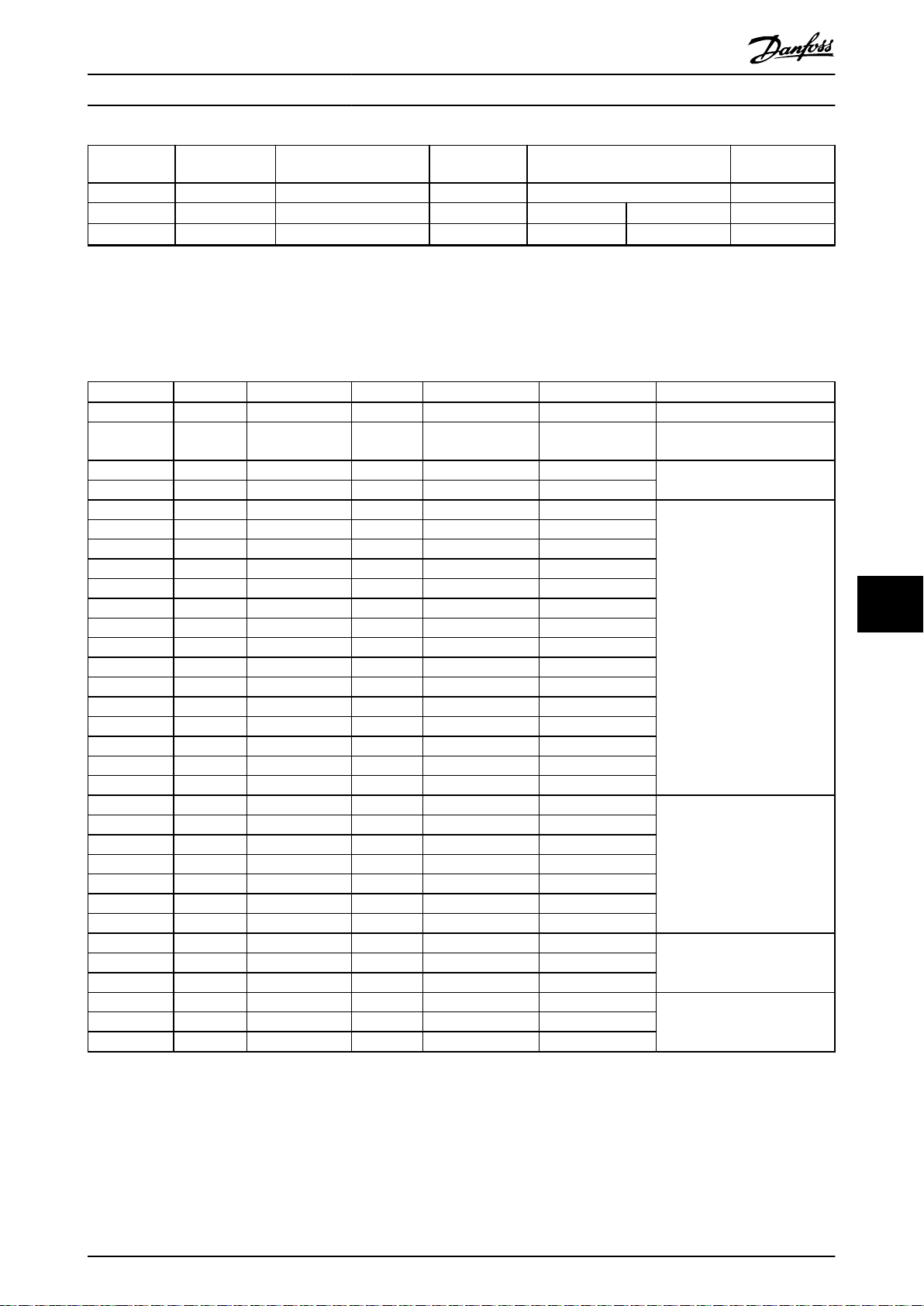
Specications Design Guide
P/N Resistance Continuous power
100% load Power cables
[W]
175N2400 310 200 No 1.5 16
Table 9.3 Electrical Data: Product Types BWD and BWG
1) 510 mm (20 in) unshielded cables.
2) 800 mm (31.5 in) Ø8 shielded cables.
Temperature
switch
Wire cross-section
[mm2]
[AWG]
9.6 Mechanical Data: Product Types BWD and BWG
P/N Weight Enclosure rating
[kg (lb)] [IP class]
175U0089 0.55 (1.21) 65 Y BWD500060 BWD500xxx
175U0090 1.05 (2.31) 65 Y BWD600080 BWD600xxx
175U0091 1.05 (2.31) 65 Y BWD600072 BWD600xxx
175U0982 0.55 (1.21) 65 Y BWD500620 BWD500xxx
175U0983 0.55 (1.21) 65 Y BWD500430 BWD500xxx
175U0984 0.55 (1.21) 65 Y BWD500310 BWD500xxx
175U0985 0.55 (1.21) 65 Y BWD500300 BWD500xxx
175U0986 0.55 (1.21) 65 Y BWD500240 BWD500xxx
175U0987 0.55 (1.21) 65 Y BWD500210 BWD500xxx
175U0988 0.55 (1.21) 65 Y BWD500160 BWD500xxx
175U0989 0.55 (1.21) 65 Y BWD500150 BWD500xxx
175U0990 0.55 (1.21) 65 Y BWD500130 BWD500xxx
175U0991 0.55 (1.21) 65 Y BWD500100 BWD500xxx
175U0992 0.55 (1.21) 65 Y BWD500072 BWD500xxx
175U0993 0.55 (1.21) 65 Y BWD500050 BWD500xxx
175U0994 0.55 (1.21) 65 Y BWD500035 BWD500xxx
175U0995 0.55 (1.21) 65 Y BWD500027 BWD500xxx
175U0996 0.55 (1.21) 65 Y BWD500040 BWD500xxx
175U1000 0.28 (0.62) 65 Y BWD250830 BWD250xxx
175U1001 0.28 (0.62) 65 Y BWD250620 BWD250xxx
175U1002 0.28 (0.62) 65 Y BWD250430 BWD250xxx
175U1003 0.28 (0.62) 65 Y BWD250330 BWD250xxx
175U1004 0.28 (0.62) 65 Y BWD250220 BWD250xxx
175U1005 0.28 (0.62) 65 Y BWD250150 BWD250xxx
175U1006 0.28 (0.62) 65 Y BWD250100 BWD250xxx
175N2395 0.41 (0.90) 65 Y BWG250430 BWG250xxx
175N2396 0.41 (0.90) 65 Y BWG250620 BWG250xxx
175N2397 0.41 (0.90) 65 Y BWG250830 BWG250xxx
175N2398 0.68 (1.50) 65 Y BWG500150 BWG500xxx
175N2399 0.68 (1.50) 65 Y BWG500210 BWG500xxx
175N2400 0.68 (1.50) 65 Y BWG500310 BWG500xxx
UL
1)
Product type Drawing type Drawing reference
Chapter 9.7.21 Figure 21 -
Chapter 9.7.22 Figure 22 -
chapter 9.7.21 Figure 21 -
Chapter 9.7.20 Figure 20 -
Chapter 9.7.23 Figure 23 -
Chapter 9.7.24 Figure 24 -
Fixed cable
see footnotes
2)
BWD500xxx
BWD600xxx
9 9
BWD500xxx
BWD250xxx
BWG250xxx
BWG500xxx
Table 9.4 Mechanical Data: Product Types BWD and BWG
1) Y=yes, N=no.
MG06H102 Danfoss A/S © 09/2016 All rights reserved. 53
Page 56

2
1
[0.71]
18
[L+5.59]
L+142
L1
L
[3.74]
95
[3.96]
100
[9.37]
238
[10.24]
260
130BD236.10
Specications
9.7 Mechanical Drawings
9.7.1 Figure 1 - 914CBT-HxxxDHT
VLT® Brake Resistor MCE 101
99
1 Hot surface warning x3
2 Nameplate
Illustration 9.1 IP21, Side View and Top View
54 Danfoss A/S © 09/2016 All rights reserved. MG06H102
Page 57

Specications Design Guide
Danfoss P/N Typecode
175U3032 MCE101A42R0P1K70E21TAW 42 460 18.11 360 14.17 9.2 (20.3)
175U3037 MCE101A31R0P1K70E21TAW 31 460 18.11 360 14.17 9.2 (20.3)
175U3039 MCE101A28R0P1K40E21TAW 28 400 15.75 300 11.81 8.2 (18.1)
175U3043 MCE101A27R0P2K20E21TAW 27 560 22.05 460 18.11 11 (24.3)
175U3047 MCE101A22R0P1K70E21TAW 22 460 18.11 360 14.17 9.2 (20.3)
175U3049 MCE101A19R0P2K20E21TAW 19 560 22.05 460 11.81 11 (24.3)
175U3055 MCE101A14R0P2K80E21TAW 14 660 25.98 560 22.05 12.8 (28.2)
175U3061 MCE101A12R0P3K20E21TAW 12 760 29.92 660 25.98 14.6 (32.2)
175U3073 MCE101A5R70P1K40E21TAW 5.7 400 15.75 300 11.81 8.2 (18.1)
175U3080 MCE101A3R50P2K20E21TAW 3.5 560 22.05 460 11.81 11 (24.3)
175U3086 MCE101A2R80P3K20E21TAW 2.8 760 29.92 660 25.98 14.6 (32.2)
175U3106 MCE101A145RP2K20E21TAW 145 560 22.05 460 11.81 11 (24.3)
175U3122 MCE101A200RP1K70E21TAW 200 460 18.11 360 14.17 9.2 (20.3)
175U3126 MCE101A145RP1K70E21TAW 145 460 18.11 360 14.17 9.2 (20.3)
175U3130 MCE101A110RP2K20E21TAW 110 560 22.05 460 18.11 11 (24.3)
175U3132 MCE101A105RP3K20E21TAW 105 760 29.92 660 25.98 14.6 (32.2)
175U3138 MCE101A80R0P2K20E21TAW 80 560 22.05 460 18.11 11 (24.3)
175U3140 MCE101A72R0P2K80E21TAW 72 660 25.98 560 22.05 12.8 (28.2)
175U3146 MCE101A56R0P2K80E21TAW 56 660 25.98 560 22.05 12.8 (28.2)
175U3152 MCE101A48R0P1K40E21TAW 48 400 15.75 300 11.81 8.2 (18.1)
175U3160 MCE101A35R0P1K70E21TAW 35 460 18.11 360 14.17 9.2 (20.3)
175U3168 MCE101A27R0P2K20E21TAW 27 560 22.05 460 18.11 11 (24.3)
175U3172 MCE101A18R0P3K20E21TAW 18 760 29.92 660 25.98 14.6 (32.2)
175U3410 MCE101A27R0P1K40E21TAW 27 400 15.75 300 11.81 8.2 (18.1)
175U3412 MCE101A18R0P2K20E21TAW 18 560 22.05 460 18.11 11 (24.3)
175U3414 MCE101A13R0P3K20E21TAW 13 760 29.92 660 25.98 14.6 (32.2)
175U3424 MCE101A110RP1K70E21TAW 110 460 18.11 360 14.17 9.2 (20.3)
175U3428 MCE101A56R0P3K20E21TAW 56 760 29.92 660 25.98 14.6 (32.2)
175U3438 MCE101A100RP2K20E21TAW 100 560 22.05 460 18.11 11 (24.3)
175U3440 MCE101A72R0P3K20E21TAW 72 760 29.92 660 25.98 14.6 (32.2)
175U3446 MCE101A5R70P1K40E21TAW 5.7 400 15.75 300 11.81 8.2 (18.1)
175U3448 MCE101A3R50P2K80E21TAW 3.5 660 25.98 560 22.05 12.8 (28.2)
175U3460 MCE101A38R0P1K40E21TAW 38 400 15.75 300 11.81 8.2 (18.1)
175U3462 MCE101A19R0P2K80E21TAW 19 660 25.98 560 22.05 12.8 (28.2)
175U3464 MCE101A14R0P3K20E21TAW 14 760 29.92 660 25.98 14.6 (32.2)
175U3468 MCE101A52R0P1K40E21TAW 52 400 15.75 300 11.81 8.2 (18.1)
175U3470 MCE101A31R0P2K20E21TAW 31 560 22.05 460 18.11 11 (24.3)
175U3472 MCE101A27R0P2K80E21TAW 27 660 25.98 560 22.05 12.8 (28.2)
175U3479 MCE101A22R0P3K20E21TAW 22 760 29.92 660 25.98 14.6 (32.2)
175U3483 MCE101A5R70P1K70E21TAW 5.7 460 18.11 360 14.17 9.2 (20.3)
[Ω]
L ±2 mm L ±0.08 in L1 ±2 mm L1 ±0.08 in
Weight [kg
(lb)]
9 9
Table 9.5 Mechanical Dimensions
MG06H102 Danfoss A/S © 09/2016 All rights reserved. 55
Page 58

130BD237.10
1
[2.41]
61
130BD241.10
[0.47]
12
[0.94]
24
[0.55]
14
[0.26]
6.5
[1.89]
48
[2.52]
64
1
2
3
4
5
130BD238.10
Specications
1 Torque: 1–1.4 Nm (8.86–12.34 lb-in)
Illustration 9.2 IP21, End View, Connection Box
VLT® Brake Resistor MCE 101
99
1 Resistor connection:
Marked RB1/RB2
Type: Phoenix G10/2
Illustration 9.3 Mounting Hole
IEC: 0.5–10 mm2/800 V
UL: AWG 20–6/600 V
Wire stripping: 12 mm (0.47 in)
Torque: 1.5–1.8 Nm (13.28–15.94 lb-in)
2 Temperature switch connection
Marked: T1/T2
Type: Phoenix G5/2 with screw connection
IEC: 0.2–4 mm2/500 V
UL: AWG 24–12 /300 V
Wire stripping: 8 mm (0.31 in)
Torque: 0.7 Nm (6.2 lb-in)
3 PE: M5
Torque 2–2.7 Nm (17.71–23.91 lb-in)
4 For temperature switch cable:
Clamping range: 3.5–7.0 mm (0.14–0.28 lb-in)
5 For resistor cable:
Cable gland with internal connection for braid
Clamping range: 9.0–16.5 mm (0.35–0.65 lb-in)
Illustration 9.4 Connection Box
56 Danfoss A/S © 09/2016 All rights reserved. MG06H102
Page 59

130BD240.10
130BD239.10
Specications Design Guide
Illustration 9.5 IP21, 3D View
Mechanical mounting (see Illustration 9.6):
Vertical with connection box down (IP21), or
•
Horizontal (IP20)
•
Illustration 9.6 Mechanical Mounting
9 9
MG06H102 Danfoss A/S © 09/2016 All rights reserved. 57
Page 60

[9.37]
238
L
L1
[0.98]
25
[1.97]
50
39.37
+1.97
0.00
1000
+50
0
1
2
3
130BD523.10
Specications
9.7.2 Figure 2 - 914CBT-HxxxCHT
VLT® Brake Resistor MCE 101
99
1 Hot surface warning x3
2 Nameplate
Illustration 9.7 IP54, Side View and Top View
Resistor cable
Temperature switch
Table 9.6 Cable Details
mm2 (AWG), see Table 9.7, UL, 1000 V
180 °C (356 °F) NC, 0.50 mm2 (AWG 20), orange
58 Danfoss A/S © 09/2016 All rights reserved. MG06H102
Page 61

130BD524.10
[10.24]
260
[2.76]
70
[9.06]
230
[3.74]
95
1
[2.52]
64
[0.26]
6.5
[0.94]
24
[0.28]
R7
130BD526.10
Specications Design Guide
Danfoss code Typecode
[Ω] L ±2 mm L ±0.08inL1 ±2mmL1 ±0.08inL1 ±0.08 in
[mm
2
AWG]
175U3305 MCE101A27R0P1k40E54CAW 27 400 15.75 300 11.81 8.2 (18.1) 6 (10)
175U3306 MCE101A18R0P2K20E54CAW 18 560 22.05 460 18.11 11 (24.3) 6 (10)
175U3307 MCE101A13R0P3K20E54CAW 13 760 29.92 660 25.98 14.6 (32.2) 6 (10)
175U3314 MCE101A110RP1k70E54CAW 110 460 18.11 360 14.17 9.2 (20.3) 6 (10)
175U3315 MCE101A80R0P2K20E54CAW 80 560 22.05 460 18.11 11 (24.3) 6 (10)
175U3316 MCE101A56R0P3K20E54CAW 56 760 29.92 660 25.98 14.6 (32.2) 6 (10)
175U3322 MCE101A145RP1K70E54CAW 145 460 18.11 360 14.17 9.2 (20.3) 2.5 (14)
175U3323 MCE101A100RP2K20E54CAW 100 560 22.05 460 18.11 11 (24.3) 6 (10)
175U3324 MCE101A72R0P3K20E54CAW 72 760 29.92 660 25.98 14.6 (32.2) 6 (10)
175U3330 MCE101A5R70P1K40E54CAW 5.7 400 15.75 300 11.81 8.2 (18.1) 6 (10)
175U3331 MCE101A5R70P1K70E54CAW 5.7 460 18.11 360 14.17 9.2 (20.3) 6 (10)
175U3332 MCE101A3R50P2K20E54CAW 3.5 560 22.05 460 18.11 11 (24.3) 6 (10)
175U3333 MCE101A3R50P2K80E54CAW 3.5 660 25.98 560 22.05 12.8 (28.2) 6 (10)
175U3334 MCE101A2R80P3K20E54CAW 2.8 760 29.92 660 25.98 14.6 (32.2) 6 (10)
175U3339 MCE101A28R0P1K40E54CAW 28 400 15.75 300 11.81 8.2 (18.1) 6 (10)
175U3340 MCE101A22R0P1K70E54CAW 22 460 18.11 360 14.17 9.2 (20.3) 6 (10)
175U3341 MCE101A14R0P2K80E54CAW 14 660 25.98 560 22.05 12.8 (28.2) 6 (10)
175U3347 MCE101A38R0P1K40E54CAW 38 400 15.75 300 11.81 8.2 (18.1) 6 (10)
175U3348 MCE101A31R0P1K70E54CAW 31 460 18.11 360 14.17 9.2 (20.3) 6 (10)
175U3349 MCE101A27R0P2K20E54CAW 27 560 22.05 460 18.11 11 (24.3) 6 (10)
175U3350 MCE101A19R0P2K80E54CAW 19 660 25.98 560 22.05 12.8 (28.2) 6 (10)
175U3352 MCE101A52R0P1K40E54CAW 52 400 15.75 300 11.81 8.2 (18.1) 6 (10)
175U3353 MCE101A42R0P1K70E54CAW 42 460 18.11 360 14.17 9.2 (20.3) 6 (10)
175U3354 MCE101A31R0P2K20E54CAW 31 560 22.05 460 18.11 11 (24.3) 6 (10)
175U3355 MCE101A27R0P2K80E54CAW 27 660 25.98 560 22.05 12.8 (28.2) 6 (10)
175U3356 MCE101A22R0P3K20E54CAW 22 760 29.92 660 25.98 14.6 (32.2) 6 (10)
175U3357 MCE101A19R0P2k20E54CAW 19 560 22.05 460 18.11 11 (24.3) 6 (10)
175U3358 MCE101A14R0P3k20E54CAW 14 760 29.92 660 25.98 14.6 (32.2) 6 (10)
175U3359 MCE101A12R0P3K20E54CAW 12 760 29.92 660 25.98 14.6 (32.2) 6 (10)
9 9
Table 9.7 Mechanical Dimensions
1 PE: M6
Torque 4.2–4.8 Nm (37.17–42.48 lb-in)
Illustration 9.8 IP54, End View, Cable End
Illustration 9.9 Mounting Hole
MG06H102 Danfoss A/S © 09/2016 All rights reserved. 59
Page 62

130BD525.10
130BD885.10
Specications
Illustration 9.10 IP54, 3D View
Mechanical mounting (see Illustration 9.11):
Vertical with cables down, or
•
Horizontal
•
VLT® Brake Resistor MCE 101
99
Illustration 9.11 Mechanical Mounting
60 Danfoss A/S © 09/2016 All rights reserved. MG06H102
Page 63

L
L1
[0.71]
18
[L+3.11]
L+79
[3.74]
95
[3.96]
100
[9.37]
238
[10.24]
260
1
2
130BD230.10
Specications Design Guide
9.7.3 Figure 3 - 914CBT-HxxxBHT
1 Hot surface warning x3
2 Nameplate
Illustration 9.12 IP65, Side View and Top View
Danfoss P/N Typecode
175U3033 MCE101A42R0P1K70E65TAW 42 460 18.11 360 14.17 9.2 (20.3)
175U3038 MCE101A31R0P1K70E65TAW 31 460 18.11 360 14.17 9.2 (20.3)
175U3040 MCE101A28R0P1K40E65TAW 28 400 15.75 300 11.81 8.2 (18.1)
175U3044 MCE101A27R0P2K20E65TAW 27 560 22.05 460 18.11 11 (24.3)
175U3048 MCE101A22R0P1K70E65TAW 22 460 18.11 360 14.17 9.2 (20.3)
175U3050 MCE101A19R0P2K20E65TAW 19 560 22.05 460 18.11 11 (24.3)
175U3056 MCE101A14R0P2K80E65TAW 14 660 25.98 560 22.05 12.8 (28.2)
175U3062 MCE101A12R0P3K20E65TAW 12 760 29.92 660 25.98 14.6 (32.2)
175U3074 MCE101A5R70P1K40E65TAW 5.7 400 15.75 300 11.81 8.2 (18.1)
175U3081 MCE101A3R50P2K20E65TAW 3.5 560 22.05 460 18.11 11 (24.3)
175U3087 MCE101A2R80P3K20E65TAW 2.8 760 29.92 660 25.98 14.6 (32.2)
[Ω]
L ±2
mm
L ±0.08 in
L1 ±2
mm
L1 ±0.08 in
Weight [kg
9 9
(lb)]
MG06H102 Danfoss A/S © 09/2016 All rights reserved. 61
Page 64

130BD231.10
[1.95]
49
1
[0.55]
14
[0.26]
6.5
[1.89]
48
[2.52]
64
[0.47]
12
[0.94]
24
130BD235.10
Specications
VLT® Brake Resistor MCE 101
Danfoss P/N Typecode
[Ω]
L ±2
mm
L ±0.08 in
L1 ±2
mm
L1 ±0.08 in
Weight [kg
(lb)]
175U3107 MCE101A145RP2K20E65TAW 145 560 22.05 460 18.11 11 (24.3)
175U3123 MCE101A200RP1K70E65TAW 200 460 18.11 360 14.17 9.2 (20.3)
175U3127 MCE101A145RP1K70E65TAW 145 460 18.11 360 14.17 9.2 (20.3)
175U3131 MCE101A110RP2K20E65TAW 110 560 22.05 460 18.11 11 (24.3)
175U3133 MCE101A105RP3K20E65TAW 105 760 29.92 660 25.98 14.6 (32.2)
175U3139 MCE101A80R0P2K20E65TAW 80 560 22.05 460 18.11 11 (24.3)
175U3141 MCE101A72R0P2K80E65TAW 72 660 25.98 560 22.05 12.8 (28.2)
175U3147 MCE101A56R0P2K80E65TAW 56 660 25.98 560 22.05 12.8 (28.2)
175U3153 MCE101A48R0P1K40E65TAW 48 400 15.75 300 11.81 8.2 (18.1)
175U3161 MCE101A35R0P1K70E65TAW 35 460 18.11 360 14.17 9.2 (20.3)
175U3169 MCE101A27R0P2K20E65TAW 27 560 22.05 460 18.11 11 (24.3)
175U3173 MCE101A18R0P3K20E65TAW 18 760 29.92 660 25.98 14.6 (32.2)
175U3409 MCE101A27R0P1K40E65TAW 27 400 15.75 300 11.81 8.2 (18.1)
175U3411 MCE101A18R0P2K20E65TAW 18 560 22.05 460 18.11 11 (24.3)
175U3413 MCE101A13R0P3K20E65TAW 13 760 29.92 660 25.98 14.6 (32.2)
175U3423 MCE101A110RP1K70E65TAW 110 460 18.11 360 14.17 9.2 (20.3)
175U3427 MCE101A56R0P3K20E65TAW 56 760 29.92 660 25.98 14.6 (32.2)
175U3437 MCE101A100RP2K20E65TAW 100 560 22.05 460 18.11 11 (24.3)
175U3439 MCE101A72R0P3K20E65TAW 72 760 29.92 660 25.98 14.6 (32.2)
175U3445 MCE101A5R70P1K40E65TAW 5.7 400 15.75 300 11.81 8.2 (18.1)
175U3447 MCE101A3R50P2K80E65TAW 3.5 660 25.98 560 22.05 12.8 (28.2)
99
175U3459 MCE101A38R0P1K40E65TAW 38 400 15.75 300 11.81 8.2 (18.1)
175U3461 MCE101A19R0P2K80E65TAW 19 660 25.98 560 22.05 12.8 (28.2)
175U3463 MCE101A14R0P3K20E54TAW 14 760 29.92 660 25.98 14.6 (32.2)
175U3467 MCE101A52R0P1K40E65TAW 52 400 15.75 300 11.81 8.2 (18.1)
175U3469 MCE101A31R0P2K20E65TAW 31 560 22.05 460 18.11 11 (24.3)
175U3471 MCE101A27R0P2K80E65TAW 27 660 25.98 560 22.05 12.8 (28.2)
175U3480 MCE101A22R0P3K20E65TAW 22 760 29.92 660 25.98 14.6 (32.2)
175U3484 MCE101A5R70P1K70E65TAW 5.7 460 18.11 360 14.17 9.2 (20.3)
Table 9.8 Mechanical Dimensions
1 Torque 2–3 Nm (17.71–26.57 lb-in)
Illustration 9.13 IP65, End View, Connection Box
62 Danfoss A/S © 09/2016 All rights reserved. MG06H102
Illustration 9.14 Mounting Hole
Page 65

1
2
3
4
5
130BD232.10
130BD234.10
130BD233.10
Specications Design Guide
1 PE: M4
Torque 2–3 Nm (17.71–26.57 lb-in)
2 Temperature switch connection:
Marked: T1/T2.
Type: PHOENIX G5/2 with screw connection
IEC: 0.2–4 mm2/500 V
UL: AWG 24–12/300 V
Wire stripping: 8 mm (0.31 in)
Torque: 0.7 Nm (6.2 lb-in)
3 For temperature switch cable:
Clamping range: 3.5–7.0 mm (0.14–0.28 in)
4 For resistor cable:
Cable gland with internal connection for braid
Clamping range: 9.0–16.5 mm (0.35–0.65 in)
5 Resistor connection:
Marked RB1/RB2
Type: PHOENIX G10/2
IEC: 0.5–10 mm2/800 V
UL: AWG 20–6/600 V
Wire stripping: 12 mm (0.47 in)
Torque: 1.5–1.8 Nm (13.28–15.94 lb-in)
Mechanical mounting (see Illustration 9.11):
Vertical with connection box down, or
•
Horizontal
•
Illustration 9.17 Mechanical Mounting
9 9
Illustration 9.15 Connection Box
Illustration 9.16 IP65, 3D View
MG06H102 Danfoss A/S © 09/2016 All rights reserved. 63
Page 66

[ 4,53 ]
115
[ 4,74 ]
120
L
L1
[0,71]
18
[ 4,02 ]
102
[ 4,88 ]
124
[L+5,63]
L+143
1
2
130BD224.10
Specications
9.7.4 Figure 4 - 914CBR-VxxxDT
VLT® Brake Resistor MCE 101
99
1 Nameplate
2 Hot surface warning x2
Illustration 9.18 IP21, Side View and Top View
Danfoss P/N Typecode
175U3009 MCE101A200RP360RE21TAW 200 210 8.27 110 4.33 1.8 (4.0)
175U3012 MCE101A145RP450RE21TAW 145 260 10.24 160 6.30 2.4 (5.3)
175U3014 MCE101A145RP280RE21TAW 145 160 6.30 70 2.76 1.3 (2.9)
175U3017 MCE101A110RP360RE21TAW 110 210 8.27 110 4.33 1.8 (4.0)
175U3019 MCE101A105RP570RE21TAW 105 330 12.99 230 9.06 3 (6.6)
175U3022 MCE101A80R0P450RE21TAW 80 260 10.24 160 6.30 2.4 (5.3)
175U3024 MCE101A72R0P960RE21TAW 72 560 22.05 460 18.11 4.6 (10.1)
175U3027 MCE101A56R0P680RE21TAW 56 400 15.75 300 11.81 3.5 (7.7)
175U3029 MCE101A52R0P1K29E21TAW 52 760 29.92 660 25.98 6.1 (13.4)
175U3034 MCE101A38R0P1K13E21TAW 38 660 25.98 560 22.05 5.4 (11.9)
175U3041 MCE101A27R0P280RE21TAW 27 160 6.30 70 2.76 1.3 (2.9)
175U3053 MCE101A18R0P450RE21TAW 18 260 10.24 160 6.30 2.4 (5.3)
175U3059 MCE101A13R0P680RE21TAW 13 400 15.75 300 11.81 3.5 (7.7)
175U3068 MCE101A9R00P1K13E21TAW 9 660 25.98 560 22.05 5.4 (11.9)
175U3102 MCE101A1K20P360RE21TAW 1200 210 8.27 110 4.33 1.8 (4.0)
175U3104 MCE101A850RP280RE21TAW 850 160 6.30 70 2.76 1.3 (2.9)
175U3108 MCE101A630RP360RE21TAW 630 210 8.27 110 4.33 1.8 (4.0)
175U3110 MCE101A570RP570RE21TAW 570 330 12.99 230 9.06 3 (6.6)
175U3112 MCE101A415RP790RE21TAW 415 460 18.11 360 14.17 3.9 (8.6)
175U3114 MCE101A410RP570RE21TAW 410 330 12.99 230 9.06 3 (6.6)
[Ω]
L ±2 mm L ±0.08 in L1 ±2 mm L1 ±0.08 in
Weight [kg
(lb)]
64 Danfoss A/S © 09/2016 All rights reserved. MG06H102
Page 67

[2,13]
54
1
130BD225.10
[0,47]
12
[2,52]
64
[0,55]
14
[0,94]
24
[0,26]
6,5
[1,89]
48
130BD229.10
Specications Design Guide
Danfoss P/N Typecode
[Ω]
L ±2 mm L ±0.08 in L1 ±2 mm L1 ±0.08 in
Weight [kg
(lb)]
175U3116 MCE101A270RP790RE21TAW 270 460 18.11 360 14.17 3.9 (8.6)
175U3118 MCE101A270RP1k13E21TAW 270 660 25.98 560 22.05 5.4 (11.9)
175U3120 MCE101A200RP1k13E21TAW 200 660 25.98 560 22.05 5.4 (11.9)
175U3124 MCE101A145RP450RE21TAW 145 260 10.24 160 6.30 2.4 (5.3)
175U3136 MCE101A100RP570RE21TAW 100 330 12.99 230 9.06 3 (6.6)
175U3144 MCE101A70R0P790RE21TAW 70 460 18.11 360 14.17 3.9 (8.6)
175U3402 MCE101A100RP450RE21TAW 100 260 10.24 160 6.30 2.4 (5.3)
175U3404 MCE101A70R0P570RE21TAW 70 330 12.99 230 9.06 3 (6.6)
175U3406 MCE101A48R0P960RE21TAW 48 560 22.05 460 18.11 4.6 (10.1)
175U3408 MCE101A35R0P1K13E21TAW 35 660 25.98 560 22.05 5.4 (11.9)
175U3416 MCE101A410RP450RE21TAW 410 260 10.24 160 6.30 2.4 (5.3)
175U3418 MCE101A270RP570RE21TAW 270 330 12.99 230 9.06 3 (6.6)
175U3420 MCE101A200RP960RE21TAW 200 560 22.05 460 18.11 4.6 (10.1)
175U3422 MCE101A145RP1K13E21TAW 145 660 25.98 560 22.05 5.4 (11.9)
175U3430 MCE101A570RP450RE21TAW 570 260 10.24 160 6.30 2.4 (5.3)
175U3432 MCE101A470RP570RE21TAW 415 330 12.99 230 9.06 3 (6.6)
175U3434 MCE101A270RP960RE21TAW 270 560 22.05 460 18.11 4.6 (10.1)
175U3436 MCE101A200RP1K13E21TAW 200 660 25.98 560 22.05 5.4 (11.9)
175U3442 MCE101A18R0P570RE21TAW 18 330 12.99 230 9.06 3 (6.6)
175U3450 MCE101A110RP450RE21TAW 110 260 10.24 160 6.30 2.4 (5.3)
175U3452 MCE101A80R0P570RE21TAW 80 330 12.99 230 9.06 3 (6.6)
175U3456 MCE101A72R0P680RE21TAW 72 400 15.75 300 11.81 3.5 (7.7)
175U3458 MCE101A52R0P1K13E21TAW 52 660 25.98 560 22.05 5.4 (11.9)
175U3466 MCE101A72R0P1K13E21TAW 72 660 25.98 560 22.05 5.4 (11.9)
175U3477 MCE101A27R0P360RE21TAW 27 210 8.27 110 4.33 1.8 (4.0)
175U3481 MCE101A105RP790RE21TAW 105 460 18.11 360 14.17 3.9 (8.6)
9 9
Table 9.9 Mechanical Dimensions
1 Torque 1–1.4 Nm (8.86–12.34 lb-in)
Illustration 9.19 IP21, End View, Connection Box
Illustration 9.20 Mounting Hole
MG06H102 Danfoss A/S © 09/2016 All rights reserved. 65
Page 68

1
2
3
4
5
130BD226.10
130BD228.10
130BD227.11
Specications
VLT® Brake Resistor MCE 101
Illustration 9.22 IP21, 3D View
Mechanical mounting (see Illustration 9.23):
•
•
Vertical with connection box down (IP21), or
Horizontal (IP20)
99
1 Resistor connection:
Marked RB1/RB2
Type: Phoenix G10/2
IEC: 0.5–10 mm2/800 V
UL: AWG 20–6/600 V
Wire stripping: 12 mm (0.47 in)
Torque: 1.5–1.8 Nm (13.28–15.94 lb-in)
2 Temperature switch connection
Marked: T1/T2
Type: Phoenix G5/2 with screw connection
IEC: 0.2–4 mm2/500 V
UL: AWG 24–12/300 V
Wire stripping: 8 mm (0.31 in)
Torque: 0.7 Nm (6.2 lb-in)
3 PE: M5
Torque 2–2.7 Nm (17.71–23.91 lb-in)
4 For temperature switch cable: Clamping range: 3.5–7.0 mm
(0.14–0.28 lb-in)
5 For resistor cable:
Cable gland with internal connection for braid
Clamping range: 9.0–16.5 mm (0.35–0.65 lb-in)
Illustration 9.21 Connection Box
Illustration 9.23 Mechanical Mounting
66 Danfoss A/S © 09/2016 All rights reserved. MG06H102
Page 69

+1,97
0,00
+50
0
[39,37]
1000
1
[ 4,74 ]
120
[ 4,53 ]
115
2
[0,71]
18
L
L1
[ 4,02 ]
102
[ 4,88 ]
124
130BD219.10
Specications Design Guide
9.7.5 Figure 5 - 914CBR-VxxxCT
1 Nameplate
2 Hot surface warning x2
Illustration 9.24 IP54, Side View and Top View
Resistor cable
Temperature switch
1.5 mm2 (AWG 16), UL Style 1659, 600 V, 250 °C (482°F)
180 °C (356 °F) NC, 0.50 mm2 (AWG 20), orange
Table 9.10 Cable Details
Danfoss P/N Typecode
L ±2 mm L ±0.08 in L1 ±2 mm L1 ±0.08 in
[Ω]
175U3301 MCE101A100RP450RE54CAW 100 260 10.24 160 6.3 2.4 (5.3)
175U3302 MCE101A70R0P570RE54CAW 70 330 12.99 230 9.06 3 (6.6)
175U3303 MCE101A48R0P960RE54CAW 48 560 22.05 460 18.11 4.6 (10.1)
175U3304 MCE101A35R0P1K13E54CAW 35 660 25.98 560 22.05 5.4 (11.9)
175U3310 MCE101A410RP450RE54CAW 410 260 10.24 160 6.30 2.4 (5.3)
175U3311 MCE101A270RP570RE54CAW 270 330 12.99 230 9.06 3 (6.6)
175U3312 MCE101A200RP960RE54CAW 200 560 22.05 460 18.11 4.6 (10.1)
175U3313 MCE101A145RP1K13E54CAW 145 660 25.98 560 22.05 5.4 (11.9)
175U3317 MCE101A850RP280RE54CAW 850 160 6.30 70 2.76 1.3 (2.9)
175U3318 MCE101A570RP450RE54CAW 570 260 10.24 160 6.30 2.4 (5.3)
175U3319 MCE101A415RP570RE54CAW 415 330 12.99 230 9.06 3 (6.6)
175U3320 MCE101A270RP960RE54CAW 270 560 22.05 460 18.11 4.6 (10.1)
175U3321 MCE101A200RP1K13E54CAW 200 660 25.98 560 22.05 5.4 (11.9)
175U3326 MCE101A27R0P360RE54CAW 27 210 8.27 110 4.33 1.8 (4.0)
175U3327 MCE101A18R0P570RE54CAW 18 330 12.99 230 9.06 3 (6.6)
175U3328 MCE101A13R0P680RE54CAW 13 400 15.75 300 11.81 3.5 (7.7)
175U3329 MCE101A9R00P1K13E54CAW 9 660 25.98 560 22.05 5.4 (11.9)
175U3335 MCE101A110RP450RE54CAW 110 260 10.24 160 6.30 2.4 (5.3)
9 9
Weight [kg
(lb)]
MG06H102 Danfoss A/S © 09/2016 All rights reserved. 67
Page 70

130BD220.10
[0,94]
24
[0,26]
6,5
[1,89]
48
[2,52]
64
[0,47]
12
[0,55]
14
130BD223.10
1
130BD222.10
130BD221.10
Specications
VLT® Brake Resistor MCE 101
Danfoss P/N Typecode
175U3336 MCE101A80R0P570RE54CAW 80 330 12.99 230 9.06 3 (6.6)
175U3337 MCE101A56R0P680RE54CAW 56 400 15.75 300 11.81 3.5 (7.7)
175U3338 MCE101A38R0P1K13E54CAW 38 660 25.98 560 22.05 5.4 (11.9)
175U3343 MCE101A145RP450RE54CAW 145 260 10.24 160 6.30 2.4 (5.3)
175U3344 MCE101A100RP570RE54CAW 100 330 12.99 230 9.06 3 (6.6)
175U3345 MCE101A72R0P680RE54CAW 72 400 15.75 300 11.81 3.5 (7.7)
175U3346 MCE101A52R0P1K13E54CAW 52 660 25.98 560 22.05 5.4 (11.9)
175U3351 MCE101A72R0P1K13E54CAW 72 660 25.98 560 22.05 5.4 (11.9)
175U3360 MCE101A105RP790RE54CAW 105 460 18.11 360 14.17 3.9 (8.6)
Table 9.11 Mechanical Dimensions
L ±2 mm L ±0.08 in L1 ±2 mm L1 ±0.08 in
[Ω]
Weight [kg
(lb)]
Mechanical mounting (see Illustration 9.28):
Vertical with connection box down, or
•
Horizontal
•
99
Illustration 9.25 IP54, End View, Connection Box
Illustration 9.28 Mechanical Mounting
Illustration 9.26 Mounting Hole
1 PE Male Fast-On tab 6.3x0.8
Illustration 9.27 IP54, 3D View
68 Danfoss A/S © 09/2016 All rights reserved. MG06H102
Page 71

130BD213.10
1
2
[ L+2,83 ]
L+72
[0,71]
18
L
L1
[ 4,74 ]
120
[ 4,53 ]
115
[ 4,02 ]
102
[ 4,88 ]
124
Specications Design Guide
9.7.6 Figure 6 - 914CBR-VxxxBT
1 Nameplate
2 Hot surface warning x2
Illustration 9.29 IP65, Side View and Top View
Danfoss P/N Typecode
175U3010 MCE101A200RP360RE65TAW 200 210 8.27 110 4.33 1.8 (4.0)
175U3013 MCE101A145RP450RE65TAW 145 260 10.24 160 6.3 2.4 (5.3)
175U3015 MCE101A145RP280RE65TAW 145 160 6.3 70 2.76 1.3 (2.9)
175U3018 MCE101A110RP360RE65TAW 110 210 8.27 110 4.33 1.8 (4.0)
175U3020 MCE101A105RP570RE65TAW 105 330 12.99 230 9.06 3 (6.6)
175U3023 MCE101A80R0P450RE65TAW 80 260 10.4 160 6.3 2.4 (5.3)
175U3025 MCE101A72R0P960RE65TAW 72 560 22.05 460 18.11 4.6 (10.1)
175U3028 MCE101A56R0P680RE65TAW 56 400 15.75 300 11.81 3.5 (7.7)
175U3030 MCE101A52R0P1K29E65TAW 52 760 29.92 660 25.98 6.1 (13.4)
175U3035 MCE101A38R0P1K13E65TAW 38 660 25.98 560 22.05 5.4 (11.9)
175U3042 MCE101A27R0P280RE65TAW 27 160 6.3 70 2.76 1.3 (2.9)
175U3054 MCE101A18R0P450RE65TAW 18 260 10.24 160 6.3 2.4 (5.3)
175U3060 MCE101A13R0P680RE65TAW 13 400 15.75 300 11.81 3.5 (7.7)
175U3069 MCE101A9R00P1K13E65TAW 9 660 25.98 560 22.05 5.4 (11.9)
175U3103 MCE101A1K20P360RE65TAW 1200 210 8.27 110 4.3 1.8 (4.0)
175U3105 MCE101A850RP280RE65TAW 850 160 6.3 70 2.76 1.3 (2.9)
175U3109 MCE101A630RP360RE65TAW 630 210 8.27 110 4.33 1.8 (4.0)
175U3111 MCE101A570RP570RE65TAW 570 330 12.99 230 9.06 3 (6.6)
L ±2 mm L ±0.08 in L1 ±2 mm L1 ±0.08 in
[Ω]
Weight [kg
9 9
(lb)]
MG06H102 Danfoss A/S © 09/2016 All rights reserved. 69
Page 72
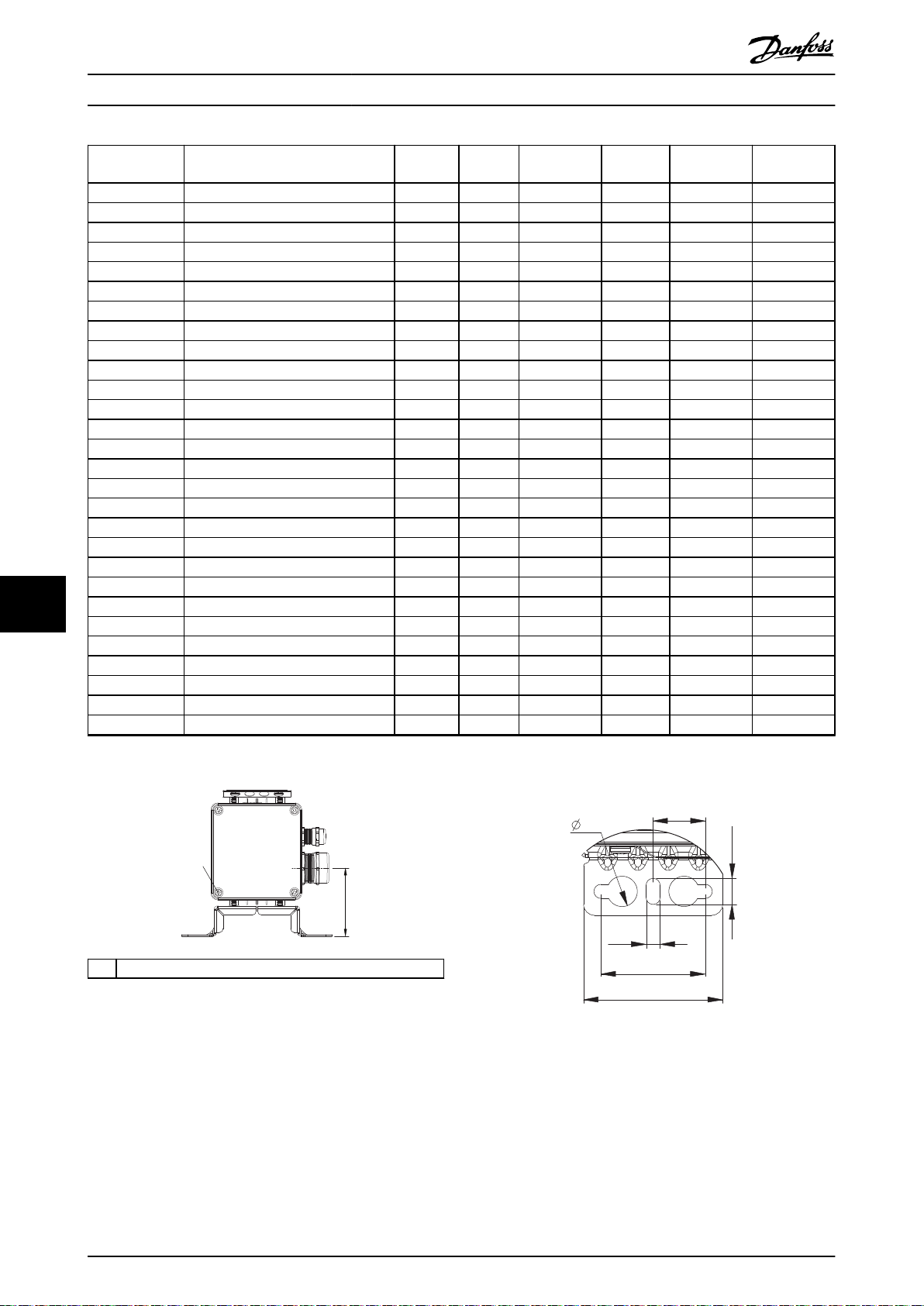
130BD214.10
[2,22 ]
56
1
[2,52]
64
[1,89]
48
[0,26]
6,5
[0,55]
14
[0,94]
24
[0,47]
12
130BD218.10
Specications
VLT® Brake Resistor MCE 101
Danfoss P/N Typecode
L ±2 mm L ±0.08 in L1 ±2 mm L1 ±0.08 in
[Ω]
Weight [kg
(lb)]
175U3113 MCE101A415RP790RE65TAW 415 460 18.11 360 14.17 3.9 (8.6)
175U3115 MCE101A410RP570RE65TAW 410 330 12.99 230 9.06 3 (6.6)
175U3117 MCE101A270RP790RE65TAW 270 460 18.11 360 14.17 3.9 (8.6)
175U3119 MCE101A270RP1K13E65TAW 270 660 25.98 560 22.05 5.4 (11.9)
175U3121 MCE101A200RP1K13E65TAW 200 660 25.98 560 22.05 5.4 (11.9)
175U3125 MCE101A145RP450RE65TAW 145 260 10.24 160 6.3 2.4 (5.3)
175U3137 MCE101A100RP570RE65TAW 100 330 12.99 230 9.06 3 (6.6)
175U3145 MCE101A70R0P790RE65TAW 70 460 18.11 360 14.17 3.9 (8.6)
175U3401 MCE101A100RP450RE65TAW 100 260 10.24 160 6.3 2.4 (5.3)
175U3403 MCE101A70R0P570RE65TAW 70 330 12.99 230 9.06 3 (6.6)
175U3405 MCE101A48R0P960RE65TAW 48 560 22.05 460 18.11 4.6 (10.1)
175U3407 MCE101A35R0P1K13E65TAW 35 660 25.98 560 22.05 5.4 (11.9)
175U3415 MCE101A410RP450RE65TAW 410 260 10.24 160 6.3 2.4 (5.3)
175U3417 MCE101A270RP570RE65TAW 270 330 12.99 230 9.06 3 (6.6)
175U3419 MCE101A200RP960RE65TAW 200 560 22.05 460 18.11 4.6 (10.1)
175U3421 MCE101A145RP1K13E65TAW 145 660 25.98 560 22.05 5.4 (11.9)
175U3429 MCE101A570RP450RE65TAW 570 260 10.24 160 6.3 2.4 (5.3)
175U3431 MCE101A415RP570RE65TAW 415 330 12.99 230 6.09 3 (6.6)
175U3433 MCE101A270RP960RE65TAW 270 560 22.05 460 18.11 4.6 (10.1)
175U3435 MCE101A200RP1K13E65TAW 200 660 25.98 560 22.05 5.4 (11.9)
175U3441 MCE101A18R0P570RE65TAW 18 330 12.99 230 9.06 3 (6.6)
99
175U3449 MCE101A110RP450RE65TAW 110 260 10.24 160 6.3 2.4 (5.3)
175U3451 MCE101A80R0P570RE65TAW 80 330 12.99 230 9.06 3 (6.6)
175U3455 MCE101A72R0P680RE65TAW 72 400 15.75 300 11.81 3.5 (7.7)
175U3457 MCE101A52R0P1K13E65TAW 52 660 25.98 560 22.05 5.4 (11.9)
175U3465 MCE101A72R0P1K13E65TAW 72 660 25.98 560 22.05 5.4 (11.9)
175U3478 MCE101A27R0P360RE65TAW 27 210 8.27 110 4.33 1.8 (4.0)
175U3482 MCE101A105RP790RE65TAW 105 460 18.11 360 14.17 3.9 (8.6)
Table 9.12 Mechanical Dimensions
1 Torque 2–3 Nm (17.71–26.57 lb-in)
Illustration 9.30 IP65, End View, Connection Box
Illustration 9.31 Mounting Hole
70 Danfoss A/S © 09/2016 All rights reserved. MG06H102
Page 73

130BD215.10
1
3
2
4
5
130BD217.10
130BD216.10
Specications Design Guide
1 PE M4
Torque 2–3 Nm (17.71–26.57 lb-in)
2 Temperature switch connection:
Marked T1/T2
Type: Phoenix G5/2 with screw connection
IEC: 0.2–4 mm2/500 V
UL: AWG 24–12/300 V
Wire stripping: 8 mm (0.31 in)
Torque: 0.7 Nm (6.2 lb-in)
3 For temperature switch cable:
Clamping range: 3.5–7.0 mm (0.14–0.28 lb-in)
4 For resistor cable:
Cable gland with internal connection for braid
Clamping range: 9.0–16.5 mm (0.35–0.65 in)
5 Resistor connection:
Marked RB1/RB2
Type: PHOENIX G10/2
IEC: 0.5–10 mm2/800 V
UL: AWG 20–6/600 V
Wire stripping: 12 mm (0.47 in)
Torque: 1.5–1.8 Nm (13.28–15.94 lb-in)
Mechanical mounting (see Illustration 9.34):
Vertical with connection box down, or
•
Horizontal
•
Illustration 9.34 Mechanical Mounting
9 9
Illustration 9.32 Connection Box
Illustration 9.33 IP65, 3D View
MG06H102 Danfoss A/S © 09/2016 All rights reserved. 71
Page 74

130BD242.10
1
2
[0.93]
23.5
[2.36]
60
[0.93]
23.5
L1
L
L1
L1
L
[2.36]
60
[0.19]
4.8
[0.19]
4.8
+
_
0.01
0.2
+
_
+
_
0.01
0.2
+
_
39.37
+ 1.97
0.00
+50
0
1000
39.37
+ 1.97
0.00
+50
0
1000
Specications
9.7.7 Figure 7 - 914CCHxxxCT
VLT® Brake Resistor MCE 101
99
1 Supplier marking
2 Supplier marking
Illustration 9.35 IP54, Side View and Top View
Resistor cable
Temperature switch
Table 9.13 Cable Details
Danfoss P/N Typecode
175U3000 MCE101A1K20P100RE54CAW 1200 145 5.71 98 3.86 0.27 (0.6)
175U3001 MCE101A850RP100RE54CAW 850 145 5.71 98 3.86 0.27 (0.6)
175U3002 MCE101A630RP100RE54CAW 630 145 5.71 98 3.86 0.27 (0.6)
175U3003 MCE101A570RP100RE54CAW 570 145 5.71 98 3.86 0.27 (0.6)
175U3004 MCE101A410RP100RE54CAW 410 145 5.71 98 3.86 0.27 (0.6)
175U3005 MCE101A415RP200RE54CAW 415 251 9.8 204 8.03 0.54 (1.2)
175U3006 MCE101A300RP100RE54CAW 300 145 5.71 98 3.86 0.27 (0.6)
175U3007 MCE101A270RP200RE54CAW 270 251 9.8 204 8.03 0.54 (1.2)
175U3008 MCE101A200RP200RE54CAW 200 251 9.8 204 8.03 0.54 (1.2)
175U3011 MCE101A200RP100RE54CAW 200 145 5.71 98 3.86 0.27 (0.6)
175U3016 MCE101A145RP100RE54CAW 145 145 5.71 98 3.86 0.27 (0.6)
175U3021 MCE101A100RP100RE54CAW 100 145 5.71 98 3.86 0.27 (0.6)
175U3026 MCE101A70R0P200RE54CAW 70 251 9.8 204 8.03 0.54 (1.2)
175U3031 MCE101A48R0P200RE54CAW 48 251 9.8 204 8.03 0.54 (1.2)
175U3036 MCE101A35R0P200RE54CAW 35 251 9.8 204 8.03 0.54 (1.2)
175U3096 MCE101A300RP200RE54CAW 300 251 9.8 204 8.03 0.54 (1.2)
1.5 mm2 (AWG 16), UL Style 1659, 600 V, 250 °C (482 °F)
180 °C (356 °F) NC, 0.50 mm2 (AWG 20), orange
[Ω]
L ±2 mm L ±0.08 in
L1 ±0.5
mm
L1 ±0.02 in
Weight [kg
(lb)]
72 Danfoss A/S © 09/2016 All rights reserved. MG06H102
Page 75

[2.52]
64
[2.99]
76
[0.15]
3.7
[0.59]
15
130BD243.10
130BD245.12
1
130BD244.10
Specications Design Guide
Danfoss P/N Typecode
175U3101 MCE101A1K20P200RE54CAW 1200 251 9.8 204 8.03 0.54 (1.2)
175U3300 MCE101A145RP300RE54CAW 145 355 13.98 154 (x2) 6.06 (x2) 1.58 (3.5)
175U3308 MCE101A850RP200RE54CAW 850 251 9.8 204 8.03 0.54 (1.2)
175U3309 MCE101A630RP300RE54CAW 630 355 13.98 154 (x2) 6.06 (x2) 1.58 (3.5)
175U3325 MCE101A35R0P300RE54CAW 35 355 13.98 154 (x2) 6.06 (x2) 1.58 (3.5)
175U3342 MCE101A200RP300RE54CAW 200 355 13.98 154 (x2) 6.06 (x2) 1.58 (3.5)
175U3361 MCE101A270RP300RE54CAW 270 355 13.98 154 (x2) 6.06 (x2) 1.58 (3.5)
Table 9.14 Mechanical Dimensions
L ±2 mm L ±0.08 in
[Ω]
L1 ±0.5
mm
L1 ±0.02 in
Weight [kg
Mechanical mounting (see Illustration 9.38):
Vertical with cables down, or
•
Horizontal
•
Illustration 9.36 IP54, End View Cable End
(lb)]
1PEMale fast-on
Tab 6.3x0.8
Illustration 9.37 IP54, 3D View
9 9
Illustration 9.38 Mechanical Mounting
MG06H102 Danfoss A/S © 09/2016 All rights reserved. 73
Page 76

175Uxxxx
6
8
3 4
30 [ 1.2 ]
45 [1.8]
160 [6.3]
85 [3.3]
30 [1.2]
130BD246.10
130BD247.10
1
2
302 [ 11.9 ]
330 [ 13.0 ]
2
3
4
5
7
10
13
13
1
5
7
130BD248.10
380 [ 15.0 ]
300 [ 11.8 ]
480 [ 18.9 ]
13
7
Specications
9.7.8 Figure 8 - 917CM13
Illustration 9.39 IP20, Side View, Right
VLT® Brake Resistor MCE 101
1 Resistor
2 Terminal board, see Illustration 9.42
3 Cable gland for load cables
4 Cable gland M16 temperature switch cable
5 Grounding bolt M6
6 Nameplate/warning signs
7 Front cover IP20
8 Back cover IP20
9 Top cover IP20
10
11 Load connection, 2x bolt M8
12 Auxiliary connection for temperature switch, porcelain
13 4x xing hole Ø 9 mm (0.35 in)
Table 9.15 Legend to Illustration 9.39 to Illustration 9.43
Temperature switch 260 °C (500 °F) (NC)
clamp 2.5 mm
2
Danfoss P/N Type code
Resistance
[Ω]
Cable gland type for load
terminals
Weight
[kg (lb)]
175U3236 MCE101C38R0P5K00E20BAW 38 M25 15 (33)
Table 9.16 Mechanical Dimensions
99
Illustration 9.41 IP20, Side View, Left
Illustration 9.40 IP20, Front View
74 Danfoss A/S © 09/2016 All rights reserved. MG06H102
Page 77

11
12
44 [ 1.7 ]
11
12
60 [ 2.4 ]
70 [ 2.8 ]
130BD249.10
7
8
9
10
130BD250.10
Specications Design Guide
Illustration 9.42 Connections
Illustration 9.43 IP20, Top View
9 9
MG06H102 Danfoss A/S © 09/2016 All rights reserved. 75
Page 78

175Uxxxx
6
8
3 4
30 [ 1.2 ]
45 [1.8]
160 [6.3]
85 [3.3]
30 [1.2]
130BD246.10
1
2
Thermocontact
260 °C (NC)
260°C
502 [ 19.8 ]
530 [ 20.9 ]
2
3
4
5
7
10
13 13
1
5
130BD252.10
Specications
9.7.9 Figure 9 - 917CM15
Illustration 9.44 IP20, Side View, Right
VLT® Brake Resistor MCE 101
1 Resistor
2 Terminal board, see Illustration 9.47
3 Cable gland for load cables
4 Cable gland M16 temperature switch cable
5 Grounding bolt M6
6 Nameplate/warning signs
7 Front cover IP20
8 Back cover IP20
9 Top cover IP20
10
11 Load connection, 2x bolt M8
12 Auxiliary connection for temperature switch, porcelain
13 4x xing hole Ø 9 mm (0.35 in)
Table 9.17 Legend to Illustration 9.44 to Illustration 9.47
Temperature switch 260 °C (500 °F) (NC)
clamp 2.5 mm
2
Danfoss P/N Type code
Resistance [Ω]
Cable gland type for load
terminals
Weight [kg (lb)]
175U3067 MCE101C9R10P9K00E20BAW 9.1 M40 21 (46)
175U3079 MCE101C4R70P9K00E20BAW 4.7 M40 21 (46)
99
175U3200 MCE101C27R0P10K0E20BAW 27.0 M25 22 (49)
175U3203 MCE101C19R0P10K0E20BAW 19.0 M25 20 (44)
175U3231 MCE101C5R50P7K00E20BAW 5.5 M32 19 (42)
175U3232 MCE101C11R0P7K00E20BAW 11 M25 19 (42)
175U3233 MCE101C5R70P6K00E20BAW 5.7 M25 19 (42)
175U3234 MCE101C5R70P8K00E20BAW 5.7 M25 20 (44)
175U3235 MCE101C3R50P9K00E20BAW 3.5 M25 21 (46)
175U3237 MCE101C28R0P6K00E20BAW 28 M25 19 (42)
175U3238 MCE101C22R0P8K00E20BAW 22 M25 20 (44)
175U3239 MCE101C38R0P6K00E20BAW 38 M25 19 (42)
175U3240 MCE101C31R0P8K00E20BAW 31 M25 20 (44)
175U3242 MCE101C52R0P6K00E20BAW 52 M25 19 (42)
175U3243 MCE101C42R0P8K00E20BAW 42 M25 20 (44)
175U3244 MCE101C31R0P10K0E20BAW 31 M25 22 (49)
175U3245 MCE101C7R00P7K00E20BAW 7 M32 20 (44)
Table 9.18 Mechanical Dimensions
Illustration 9.45 IP20, Front View
76 Danfoss A/S © 09/2016 All rights reserved. MG06H102
Page 79

130BD248.10
380 [ 15.0 ]
300 [ 11.8 ]
480 [ 18.9 ]
13
7
11
12
44 [ 1.7 ]
11
12
60 [ 2.4 ]
70 [ 2.8 ]
130BD249.10
8
7
9
10
130BD255.10
Specications Design Guide
Illustration 9.46 IP20, Side View, Left
Illustration 9.47 Connections
9 9
Illustration 9.48 IP20, Top View
MG06H102 Danfoss A/S © 09/2016 All rights reserved. 77
Page 80

130BD256.10
14
8
175Uxxxx
6
3
4
45 [1.8]
235 [9.3]
160 [6.3]
85 [3.3]
30 [1.2]
30 [1.2]
260°C
1
2
The
rmocontact
260 °C (NC)
712[28.0]
740[29.1]
13
2
5
7
1
10
4
3
5
13
130BD257.10
130BD248.10
380 [ 15.0 ]
300 [ 11.8 ]
480 [ 18.9 ]
13
7
Specications
9.7.10 Figure 10 - 917CM17
Illustration 9.49 IP20, Side View, Right
VLT® Brake Resistor MCE 101
1 Resistor
2 Terminal board, see Illustration 9.52
3 Cable gland for load cables
4 Cable gland M16 temperature switch cable
5 Grounding bolt M6
6 Nameplate/warning signs
7 Front cover IP20
8 Back cover IP20
9 Top cover IP20
10
Temperature switch 260 °C (500 °F) (NC)
11 Load connection, 2x bolt M8
12 Auxiliary connection for temperature switch, porcelain
clamp 2.5 mm
13 4x xing hole Ø 9 mm (0.35 in)
14 Second cable gland. Not in use.
Table 9.19 Legend to Illustration 9.49 to Illustration 9.53
2
Danfoss P/N Type code
Resistance
[Ω]
Cable gland type for load terminals
Weight [kg
(lb)]
175U3072 MCE101C7R40P11K0E20BAW 7.4 M40 24 (53)
99
175U3075 MCE101C6R10P13K0E20BAW 6.1 M50 25 (55)
175U3083 MCE101C3R70P11K0E20BAW 3.7 M50 24 (53)
175U3084 MCE101C3R30P13K0E20BAW 3.3 2xM25 25 (55)
175U3201 MCE101C27R0P14K0E20BAW 27.0 M25 25 (55)
175U3204 MCE101C19R0P14K0E20BAW 19 M25 25 (55)
175U3206 MCE101C14R0P14K0E20BAW 14.0 M32 25 (55)
175U3224 MCE101C3R50P14K0E20BAW 3.5 M40 25 (55)
Table 9.20 Mechanical Dimensions
Illustration 9.50 IP20, Front View
78 Danfoss A/S © 09/2016 All rights reserved. MG06H102
Illustration 9.51 IP20, Side View, Left
Page 81

11
12
44 [ 1.7 ]
11
12
60 [ 2.4 ]
70 [ 2.8 ]
130BD249.10
8
7
10
9
130BD260.10
Specications Design Guide
Illustration 9.52 Connections
9 9
Illustration 9.53 IP20, Top View
MG06H102 Danfoss A/S © 09/2016 All rights reserved. 79
Page 82

8
6
14
4
3
30 [1.2]
30 [1.2]
85 [3.3]
160 [6.3]
235 [9.3]
45 [1.8]
175Uxxxx
130BD261.10
Specications
9.7.11 Figure 11 - 917CM25
VLT® Brake Resistor MCE 101
1 Resistor
2 Terminal board, see Illustration 9.57
3 Cable gland for load cables
4 Cable gland M16 temperature switch cable
5 Grounding bolt M6
6 Nameplate/warnings signs
7 Front cover IP20
8 Back cover IP20
9 Top cover IP20
10
11 Load connection, 2x bolt M8
12 Auxiliary connection for temperature switch, porcelain
13 4x xing hole Ø 9 mm (0.35 in)
14 Second cable gland. Not in use.
Table 9.21 Legend to Illustration 9.54 to Illustration 9.58
Temperature switch 260 °C (500 °F) (NC)
clamp 2.5 mm
2
Illustration 9.54 IP20, Side View, Right
99
Danfoss P/N Type code
175U3078 MCE101C5R00P16K0E20BAW 5.0 2xM25 35 (77)
175U3082 MCE101C4R00P20K0E20BAW 4.0 2xM32 37 (82)
175U3088 MCE101C2R70P16K0E20BAW 2.7 2xM32 35 (77)
175U3091 MCE101C2R10P20K0E20BAW 2.1 2xM40 37 (82)
175U3202 MCE101C22K0P17K0E20BAW 22.0 M25 35 (77)
175U3207 MCE101C14R0P17K0E20BAW 14.0 M32 35 (77)
175U3210 MCE101C12R0P17K0E20BAW 12.0 M32 35 (77)
175U3227 MCE101C2R80P17K0E20BAW 2.8 M40 35 (77)
Table 9.22 Mechanical Dimensions
Resistance [Ω]
Cable gland type for load
terminals
Weight [kg (lb)]
80 Danfoss A/S © 09/2016 All rights reserved. MG06H102
Page 83

260°C
1
2
Thermocontact
260 °C (NC)
10
7
1
4
3
5
13
13
2
5
502 [19.8]
530 [20.9]
130BD262.10
13
380 [15.0]
480 [18.9]
600 [23.6]
7
130BD263.10
11
12
44 [ 1.7 ]
11
12
60 [ 2.4 ]
70 [ 2.8 ]
130BD249.10
8
7
9
10
130BD255.10
Specications Design Guide
Illustration 9.57 Connections
Illustration 9.55 IP20, Front View
Illustration 9.56 IP20, Side View, Left
9 9
Illustration 9.58 IP20, Top View
MG06H102 Danfoss A/S © 09/2016 All rights reserved. 81
Page 84

8
6
14
4
3
30 [1.2]
30 [1.2]
85 [3.3]
160 [6.3]
235 [9.3]
45 [1.8]
175Uxxxx
130BD261.10
Specications
9.7.12 Figure 12 - 917CM27
VLT® Brake Resistor MCE 101
1 Resistor
2 Terminal board, see Illustration 9.62
3 Cable gland for load cables
4 Cable gland M16 temperature switch cable
5 Grounding bolt M6
6 Nameplate/warning signs
7 Front cover IP20
8 Back cover IP20
9 Top cover IP20
10
11 Load connection, 2x bolt M8
12 Auxiliary connection for temperature switch, porcelain
13 4x xing hole Ø 9 mm (0.35 in)
14 Second cable gland. Not in use.
Table 9.23 Legend to Illustration 9.59 to Illustration 9.63
Temperature switch 260 °C (500 °F) (NC)
clamp 2.5 mm
2
Illustration 9.59 IP20, Side View, Right
99
Danfoss P/N Typecode
175U3085 MCE101C3R30P26K0E20BAW 3.3 2xM32 45 (99)
175U3089 MCE101C2R50P32K0E20BAW 2.5 2xM50 48 (106)
175U3093 MCE101C1R70P26K0E20BAW 1.7 2xM50 45 (99)
175U3097 MCE101C1R30P32K0E20BAW 1.3 2xM50 48 (106)
175U3205 MCE101C15R5P21K0E20BAW 15.5 M32 41 (90)
175U3208 MCE101C13R5P21K0E20BAW 13.5 M32 41 (90)
175U3209 MCE101C13R5P26K0E20BAW 13.5 M32 45 (99)
175U3211 MCE101C11R0P26K0E20BAW 11.0 M32 45 (99)
175U3213 MCE101C9R50P21K0E20BAW 9.5 M32 41 (90)
175U3216 MCE101C7R00P26K0E20BAW 7.0 M40 45 (99)
175U3241 MCE101C7R00P30K0E20BAW 7.0 M40 52 (115)
Table 9.24 Mechanical Dimensions
Resistance [Ω]
Cable gland type for
load terminals
Weight [kg (lb)]
82 Danfoss A/S © 09/2016 All rights reserved. MG06H102
Page 85

260°C
1
2
The
rmocontact
260 °C (NC)
10
7
1
13
2
5
4
3
5
13
712[28.0]
740[29.1]
130BD267.10
13
380 [15.0]
480 [18.9]
600 [23.6]
7
130BD263.10
11
12
44 [ 1.7 ]
11
12
60 [ 2.4 ]
70 [ 2.8 ]
130BD249.10
8
7
10
9
130BD260.10
Specications Design Guide
Illustration 9.60 IP20, Front View
Illustration 9.62 Connections
Illustration 9.61 IP20, Side View, Left
9 9
Illustration 9.63 IP20, Top View
MG06H102 Danfoss A/S © 09/2016 All rights reserved. 83
Page 86

130BD271.10
175Uxxxx
8
6
160 [ 6.3 ]
60 [ 2.4 ]
25 [ 1.0 ]
30 [ 1.2 ]
4
3
90 [ 3.5 ]
14
100 [ 3.9 ]
100 [ 3.9 ]
Specications
9.7.13 Figure 13 - 917CM37
VLT® Brake Resistor MCE 101
1 Resistor
2 Terminal board, see Illustration 9.67
3 Cable gland for load cables
4 Cable gland M16 temperature switch cable
5 Grounding bolt M10
6 Nameplate/warning signs
7 Front cover IP20
8 Back cover IP20
9 Top cover IP20
10
11 Load connection, 2x bolt M8
12 Auxiliary connection for temperature switch, porcelain
13 4x xing hole Ø 9 mm (0.35 in)
14 Second cable gland. Not in use.
Table 9.25 Legend to Illustration 9.64 to Illustration 9.68
Temperature switch 260 °C (500 °F) (NC)
clamp 2.5 mm
2
Illustration 9.64 IP20, Side View, Right
99
Danfoss P/N Type code
Resistance [Ω]
175U3090 MCE101C2R30P36K0E20BAW 2.3 2xM50 74 (163)
175U3092 MCE101C2R00P42K0E20BAW 2.0 2xM50 78 (172)
175U3098 MCE101C1R20P36K0E20BAW 1.2 2xM50 74 (163)
175U3099 MCE101C1R10P42K0E20BAW 1.1 2xM50 78 (172)
175U3212 MCE101C11R0P36K0E20BAW 11.0 M32 74 (163)
175U3214 MCE101C9R10P42K0E20BAW 9.1 M40 78 (172)
175U3217 MCE101C7R00P36K0E20BAW 7.0 M50 74 (163)
175U3219 MCE101C5R50P36K0E20BAW 5.5 M40 74 (163)
175U3221 MCE101C4R70P42K0E20BAW 4.7 M40 78 (172)
Table 9.26 Mechanical Dimensions
Cable gland type for load
terminals
Weight [kg (lb)]
84 Danfoss A/S © 09/2016 All rights reserved. MG06H102
Page 87

The
rmocontact
260 °C (NC)
1
2
260°C
10
1
7
3/4
5
13
12
2
11
13
712 [28.0]
740 [29.1]
130BD272.10
130BD273.10
7
380 [ 15.0 ]
480 [ 18.9 ]
13
1020 [ 40.2 ]
The
rmocontact
260 °C (NC)
1 2
97.5 [3.8]
73.5 [2.9]
11
12
35 [1.4]
224.5 [8.8]
100 [3.9]
11
12
130BD274.10
8
7
10
9
130BD260.10
Specications Design Guide
Illustration 9.67 Connections
Illustration 9.65 IP20, Front View
Illustration 9.66 IP20, Side View, Left
9 9
Illustration 9.68 IP20, Top View
MG06H102 Danfoss A/S © 09/2016 All rights reserved. 85
Page 88

130BD276.10
175Uxxxx
8
6
160 [ 6.3 ]
60 [ 2.4 ]
25 [ 1.0 ]
30 [ 1.2 ]
4 3
90 [ 3.5 ]
3
100 [ 3.9 ]
100 [ 3.9 ]
The
rmocontact
260 °C (NC)
1 2
10
13
12
2
11
3/4
5
13
1
7
712 [28.0]
740 [29.1]
130BD277.10
130BD278.10
7
770 [ 30.3 ]
870 [ 34.3 ]
13
720 [ 28.3 ]
Specications
9.7.14 Figure 14 - 917CMD27
Illustration 9.69 IP20, Side View, Right
VLT® Brake Resistor MCE 101
1 Resistor
2 Terminal board, see Illustration 9.72
3 Cable gland for load cables
4 Cable gland M16 temperature switch cable
5 Grounding bolt M10
6 Nameplate/warning signs
7 Front cover IP20
8 Back cover IP20
9 Top cover IP20
10
11 Load connection, 2xbolt M8
12 Auxiliary connection for temperature switch, porcelain
13 6 x xing hole Ø 9 mm (0.35 in)
Table 9.27 Legend to Illustration 9.69 to Illustration 9.73
Temperature switch 260 °C (500 °F) (NC)
clamp 2.5 mm
2
Danfoss P/N Type code
99
175U3094 MCE101C1R60P52K0E20BAW 1.6 2xM50 90 (198)
175U3095 MCE101C1R40P60K0E20BAW 1.4 2xM50 90 (198)
Resistance [Ω]
Cable gland type for load
terminals
Weight [kg (lb)]
175U3215 MCE101C7R40P52K0E20BAW 7.4 M40 90 (198)
175U3218 MCE101C6R10P60K0E20BAW 6.1 M50 90 (198)
175U3223 MCE101C3R70P52K0E20BAW 3.7 M50 90 (198)
175U3225 MCE101C3R30P60K0E20BAW 3.3 2xM25 90 (198)
Table 9.28 Mechanical Dimensions
Illustration 9.70 IP20, Front View
86 Danfoss A/S © 09/2016 All rights reserved. MG06H102
Illustration 9.71 IP20, Side View, Left
Page 89
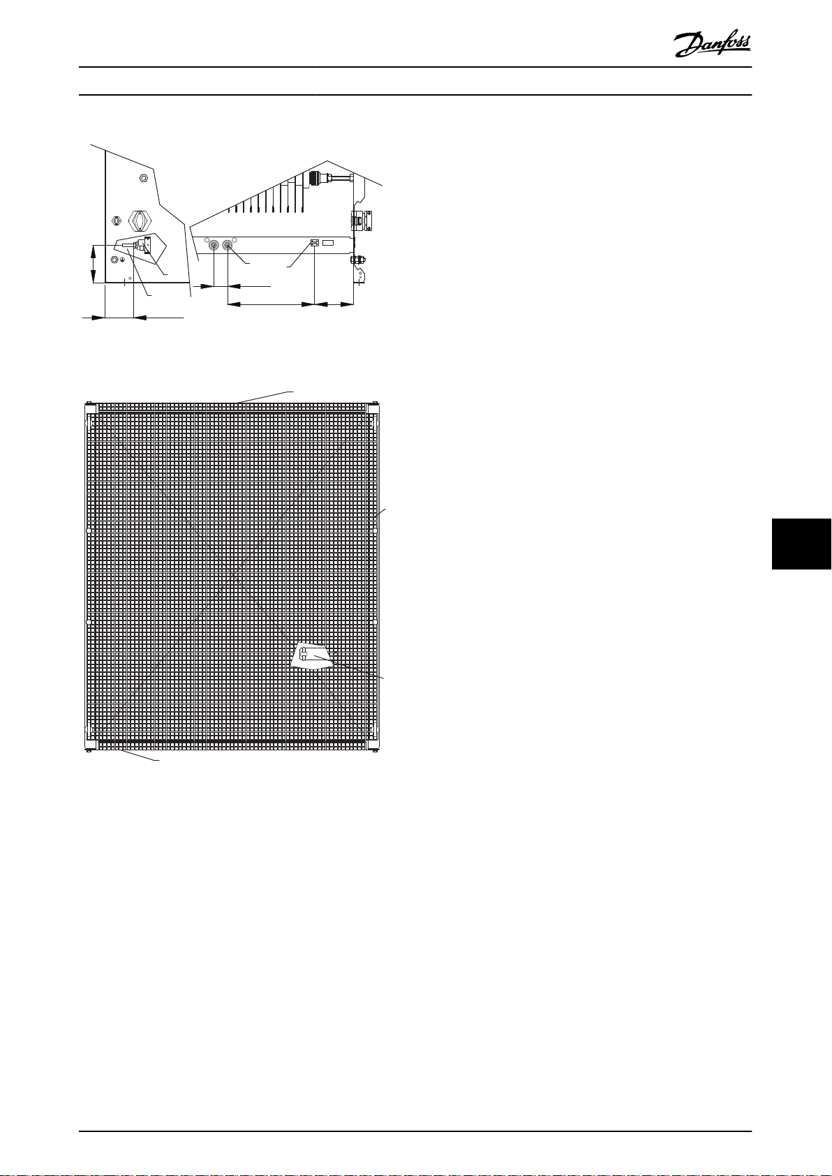
The
rmocontact
260 °C (NC)
1 2
97.5 [3.8]
73.5 [2.9]
11
12
35 [1.4]
224.5 [8.8]
100 [3.9]
11
12
130BD274.10
7
10
9
8
130BD280.10
Specications Design Guide
Illustration 9.72 Connections
Illustration 9.73 IP20, Top View
9 9
MG06H102 Danfoss A/S © 09/2016 All rights reserved. 87
Page 90

130BD281.10
175Uxxxx
8
6
160 [ 6.3 ]
60 [ 2.4 ]
25 [ 1.0 ]
30 [ 1.2 ]
4
3
90 [ 3.5 ]
3
100 [ 3.9 ]
100 [ 3.9 ]
Specications
9.7.15 Figure 15 - 917CMD37
VLT® Brake Resistor MCE 101
1 Resistor
2 Terminal board, see Illustration 9.77
3 Cable gland for load cables
4 Cable gland M16 temperature switch cable
5 Grounding bolt M10
6 Nameplate/warning signs
7 Front cover IP20
8 Back cover IP20
9 Top cover IP20
10
Temperature switch 260 °C (500 °F) (NC)
11 Load connection, 2x bolt M8
12 Auxiliary connection for temperature switch, porcelain
clamp 2.5 mm
13 6 x xing hole Ø 9 mm (0.35 in)
Table 9.29 Legend to Illustration 9.74 to Illustration 9.78
2
Illustration 9.74 IP20, Side View, Right
99
Danfoss P/N Type code
Resistance [Ω]
175U3220 MCE101C5R00P78K0E20BAW 5.0 2xM25 182 (401)
175U3222 MCE101C4R00P90K0E20BAW 4.0 2xM32 190 (419)
175U3228 MCE101C2R70P78K0E20BAW 2.7 2xM32 182 (401)
175U3230 MCE101C2R10P90K0E20BAW 2.1 2xM40 190 (419)
Table 9.30 Mechanical Dimensions
Cable gland type for load
terminals
Weight [kg (lb)]
88 Danfoss A/S © 09/2016 All rights reserved. MG06H102
Page 91

The
rmocontact
260 °C (NC)
1
2
260°C
10
1
7
3/4
5
13
12
2
11
13
712 [28.0]
740 [29.1]
130BD272.10
130BD283.10
7
770 [ 30.3 ]
870 [ 34.3 ]
13
1020 [ 40.2 ]
The
rmocontact
260 °C (NC)
1 2
97.5 [3.8]
73.5 [2.9]
11
12
35 [1.4]
224.5 [8.8]
100 [3.9]
11
12
130BD274.10
7
10
9
8
130BD280.10
Specications Design Guide
Illustration 9.77 Connections
Illustration 9.75 IP20, Front View
9 9
Illustration 9.78 IP20, Top View
Illustration 9.76 IP20, Side View, Left
MG06H102 Danfoss A/S © 09/2016 All rights reserved. 89
Page 92

130BD292.10
[L + 8.82]
L + 224
L
L1
[0.53]
13.5
L
1
2
[9.88]
251
[11.02]
280
[10.63]
270
[11.81]
300
[0.33]
8.5
Specications
VLT® Brake Resistor MCE 101
9.7.16 Figure 16 - 929CBT-VxxxGHT
99
1 Hot surface warning x3
2 Nameplate
Illustration 9.79 IP21, Side View and Top View
Danfoss P/N
Typecode
Ω
L ±2
mm
L ±0.08 in
L1 ±2
mm
L1 ±0.08 in
175U3051 MCE101A15R5P3K50E21TAW 15.5 560 22.05 530 20.87 25.5 (56.2)
175U3057 MCE101A13R5P4K20E21TAW 13.5 660 25.98 630 24.80 29 (63.9)
175U3063 MCE101A11R0P5K50E21TAW 11 760 29.92 730 28.74 32.5 (71.7)
175U3065 MCE101A9R50P4K20E21TAW 9.5 660 25.98 630 24.80 29 (63.9)
175U3070 MCE101A7R00P5K50E21TAW 7 760 29.92 730 28.74 32.5 (71.7)
175U3134 MCE101A105RP4K20E21TAW 105 660 25.98 630 24.80 29 (63.9)
175U3142 MCE101A72R0P4K20E21TAW 72 660 25.98 630 24.80 29 (63.9)
175U3148 MCE101A52R0P5K50E21TAW 52 760 29.92 730 28.74 32.5 (71.7)
175U3156 MCE101A38R0P5K50E21TAW 38 760 29.92 730 28.74 32.5 (71.7)
175U3174 MCE101A13R0P3K50E21TAW 13 560 22.05 530 20.87 25.5 (56.2)
175U3176 MCE101A9R00P5K50E21TAW 9 760 29.92 730 28.74 32.5 (71.7)
Weight [kg
(lb)]
90 Danfoss A/S © 09/2016 All rights reserved. MG06H102
Page 93

130BD293.10
[0.79]
20
1
130BD297.10
[0.71]
18
[0.33]
8.5
[0.35]
R9
1
2
3
4
5
130BD294.11
Specications Design Guide
Danfoss P/N
Typecode
Ω
L ±2
mm
L ±0.08 in
L1 ±2
mm
L1 ±0.08 in
Weight [kg
175U3178 MCE101A5R70P5K50E21TAW 5.7 760 29.92 730 28.74 32.5 (71.7)
175U3474 MCE101A15R5P4K20E21TAW 15.5 660 25.98 630 24.80 29 (63.9)
175U3476 MCE101A13R5P5K50E21TAW 13.5 760 29.92 730 28.74 32.5 (71.7)
Table 9.31 Mechanical Dimensions
(lb)]
1 Resistor connection:
9 9
Marked RB1/RB2
1 Torque 1–1.4 Nm (8.85–12.39 lb-in)
Illustration 9.80 IP21, End View, Connection Box
Illustration 9.81 Mounting Hole
Type: ENSTO KE 66
IEC: Cu 2.5–50 mm2, AI: 6–50 mm2/750 V
UL: AWG 6–1/0/600 V
Wire stripping: 23 mm (0.9 in)
Torque: 10 Nm (88.51 lb-in)
2 Temperature switch connection:
Marked: T1/T2
Type: PHOENIX G5/2 with screw connection
IEC: 0.2–4 mm2 500 V
UL: AWG 24–12/300 V
Wire stripping: 8 mm (0.31 in)
Torque: 0.7 Nm (6.2 lb-in)
3 For temperature switch cable:
Clamping range: 3.5–7.0 mm (0.14–0.28 in)
Size wrench (SW): 16 mm (0.63 in)
4 For resistor cable:
Cable gland with internal connection for braid
Clamping range: 19–28 mm
Size wrench (SW): 45 mm (1.78 in)
5 PE: M8
Torque: 4.5–5.5 Nm (39.83–48.68 lb-in)
Illustration 9.82 Connection Box
MG06H102 Danfoss A/S © 09/2016 All rights reserved. 91
Page 94

130BD296.10
130BD295.10
Specications
Illustration 9.83 IP21, 3D View
Mechanical mounting (see Illustration 9.84):
Vertical with connection box down (IP21), or
•
Horizontal (IP20)
•
VLT® Brake Resistor MCE 101
99
Illustration 9.84 Mechanical Mounting
92 Danfoss A/S © 09/2016 All rights reserved. MG06H102
Page 95

130BD286.10
[0.53]
13.5
[9.88]
251
[11.02]
280
[L + 5.31]
L + 135
L
L1
L
[3.15]
80
1
2
[10.63]
270
[0.33]
8.5
[11.81]
300
Specications Design Guide
9.7.17 Figure 17 - 929CBT-VxxxBGHT
1 Hot surface warning x3
2 Nameplate
Illustration 9.85 IP65, Side View and Top View
Danfoss code Typecode
175U3052 MCE101A15R5P3K50E65TAW 15.5 560 22.05 530 20.87 26.5 (58.4)
175U3058 MCE101A13R5P4K20E65TAW 13.5 660 25.95 630 24.8 30 (66.1)
Ω
L ±2
mm
L ±0.08 in
L1 ±2
mm
L1 ±0.08 in
Weight [kg
175U3064 MCE101A11R0p5K50E65TAW 11 760 29.92 730 28.74 33.5 (73.9)
175U3066 MCE101A9R50P4K20E65TAW 9.5 660 25.95 630 24.8 30 (66.1)
175U3071 MCE101A7R00P5K50E65TAW 7 760 29.92 730 28.74 33.5 (73.9)
175U3135 MCE101A105RP4K20E65TAW 105 660 25.95 630 24.8 30 (66.1)
175U3143 MCE101A72R0P4K20E65TAW 72 660 25.95 630 24.8 30 (66.1)
175U3149 MCE101A52R0P5K50E65TAW 52 760 29.92 730 28.74 33.5 (73.9)
175U3157 MCE101A38R0P5K50E65TAW 38 760 29.92 730 28.74 33.5 (73.9)
175U3175 MCE101A13R0P3K50E65TAW 13 560 22.05 530 20.87 26.5 (58.4)
175U3177 MCE101A9R00P5K50E65TAW 9 760 29.92 730 28.74 33.5 (73.9)
9 9
(lb)]
MG06H102 Danfoss A/S © 09/2016 All rights reserved. 93
Page 96

130BD287.10
[11.85]
301
[0.79]
20
1
130BD291.10
[0.71]
18
[0.33]
8.5
[0.35]
R9
1
2
3
45
130BD288.11
5
Specications
VLT® Brake Resistor MCE 101
Danfoss code Typecode
Ω
L ±2
mm
L ±0.08 in
L1 ±2
mm
L1 ±0.08 in
Weight [kg
(lb)]
175U3179 MCE101A5R70P5K50E65TAW 5.7 760 29.92 730 28.74 33.5 (73.9)
175U3473 MCE101A15R5P4K20E65TAW 15.5 660 25.95 630 24.8 30 (66.1)
175U3475 MCE101A13R5P5K50E65TAW 13.5 760 29.92 730 28.74 33.5 (73.9)
Table 9.32 Mechanical Dimension
1 Temperature switch connection:
Marked: T1/T2
IEC: 0.2–4 mm2/500 V
UL: AWG 24–12/300 V
99
Wire stripping: 8 mm (0.31 in)
Torque: 0.7 Nm (6.2 lb-in)
2 For temperature switch cable:
Clamping range: 3.5–7.0 mm (0.14–0.28 in)
Size wrench (SW): 16 mm (0.63 in)
1 Torque 1–1.4 Nm (8.86–12.34 lb-in)
3 For resistor cable:
Cable gland with internal connection for braid
Illustration 9.86 IP65, End View, Connection Box
Clamping range: 19–28 mm (0.74–1.1 in)
Size wrench (SW): 45 mm (1.78)
4 PE: M8
Torque 4.5–5.5 Nm (39.83–48.68 lb-in)
5 Resistor connection:
Marked RB1/RB2
IEC: Cu 2.5–50 mm2, AI: 6–50 mm2/750 V
UL: AWG 6–1/0/600 V
Wire stripping: 23 mm (0.9 in)
Torque: 10 Nm (88.51 lb-in)
Illustration 9.88 Connection Box
Illustration 9.87 Mounting Hole
94 Danfoss A/S © 09/2016 All rights reserved. MG06H102
Page 97

130BD290.10
130BD289.10
Specications Design Guide
Illustration 9.89 IP65, 3D View
Mechanical mounting (see Illustration 9.90):
Vertical with connection box down, or
•
Horizontal
•
Illustration 9.90 Mechanical Mounting
9 9
MG06H102 Danfoss A/S © 09/2016 All rights reserved. 95
Page 98

130BD304.10
[L +8.82]
L +224
L
L1
[0.53]
13.5
[11.02]
280
1
2
[0.33]
8.5
[12.2]
310
[13.39]
340
[10]
254
Specications
VLT® Brake Resistor MCE 101
9.7.18 Figure 18 - 930CBT-VxxxGHT
99
1 Hot surface warning x3
2 Nameplate
Illustration 9.91 IP21, Side View and Top View
Danfoss P/N Type code
175U3076 MCE101A5R50P6K30E21TAW 5.5 660 25.98 630 24.8 39 (86)
175U3154 MCE101A42R0P8K20E21TAW 42 760 29.92 730 28.74 44.5 (98)
L ±2
Ω
mm
L ±0.08 in
L1 ±2
mm
175U3162 MCE101A31R0P8K20E21TAW 31 760 29.92 730 28.74 44.5 (98)
175U3166 MCE101A28R0P6K30E21TAW 28 660 25.98 630 24.8 39 (86)
175U3170 MCE101A22R0P8K20E21TAW 22 760 29.92 730 28.74 44.5 (98)
175U3180 MCE101A5R70P8K20E21TAW 5.7 760 29.92 730 28.74 44.5 (98)
175U3182 MCE101A3R50P8K20E21TAW 3.5 760 29.92 730 28.74 44.5 (98)
L1 ±0.08 in
Weight [kg
(lb)]
Table 9.33 Mechanical Dimensions
96 Danfoss A/S © 09/2016 All rights reserved. MG06H102
Page 99

130BD305.10
[4.02]
102
[0.79]
20
1
[5.84]
148.3
130BD309.10
[0.71]
18
[0.33]
8.5
[0.35]
R9
1
2
3
4
5
130BD306.11
5
130BD308.10
Specications Design Guide
1 Torque 1–1.4 Nm (8.86–12.34 in)
Illustration 9.92 IP21, End View, Connection Box
Illustration 9.93 Mounting Hole
1 Resistor connection:
Marked RB1/RB2 ENSTO KE66
EIC: Cu 2.5–50 mm2, AI 6–50 mm2/750 V
UL: AWG 6–1/0/600 V
Wire stripping: 23 mm (0.9 in)
Torque: 10 Nm (90 lb-in)
2 Temperature switch connection:
Marked: T1/T2 PHOENIX G5/2
IEC: 0.2–4 mm2/500 V
UL: AWG 28–10/300 V
Wire stripping: 8 mm (0.31 in)
Torque: 0.7 Nm (6.2 lb-in)
3 For temperature switch cable:
Clamping range: 3.5–7.0 mm (0.14–0.28 in)
Size wrench (SW): 16 mm (0.63 in)
4 For resistor cable:
Cable gland with internal connection for braid
Clamping range: 19–28 mm (0.74–1.1 in)
Size wrench (SW): 45 mm (1.78 in)
5 PE: M8
Torque: 5–5.5 Nm (44.28–48.71 lb-in)
Illustration 9.94 Connection Box
9 9
Illustration 9.95 IP21, 3D View
MG06H102 Danfoss A/S © 09/2016 All rights reserved. 97
Page 100

130BD307.10
Specications
Mechanical mounting (see Illustration 9.96):
Vertical with connection box down (IP21), or
•
Horizontal (IP20)
•
Illustration 9.96 Mechanical Mounting
VLT® Brake Resistor MCE 101
99
98 Danfoss A/S © 09/2016 All rights reserved. MG06H102
 Loading...