

Page 1
MCD DeviceNet Module Instructions Important User Information
CAUTION
Remove mains and control voltage from the soft starter before attaching or removing
accessories. Failure to do so may damage the equipment.
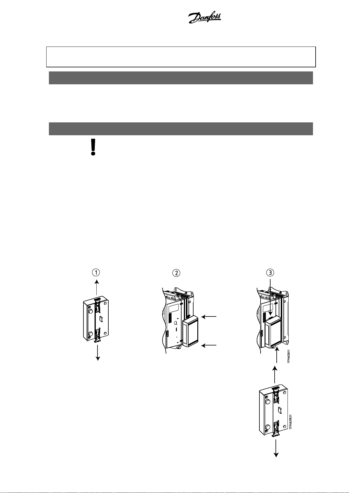
Remove the module using the following procedure:
1. Take the module off-line.
2. Remove the DeviceNet connector.
3. Remove control power and mains supply from the soft starter.
4. Fully pull out the top and bottom retaining clips on the module.
5. Pull the module away from the soft starter.
INSTALLATION INSTRUCTIONS: MCD DEVICENET MODULE
Order Code: 175G9002
1. Important User Information
Observe all necessary safety precautions when controlling the soft starter remotely. Alert
personnel that machinery may start without warning.
It is the installer's responsibility to follow all instructions in this manual and to follow correct
electrical practice.
2. Installation
Install the DeviceNet Module using the following procedure:
1. Remove control power and mains supply from the soft starter.
2. Attach the module to the soft starter as illustrated.
3. Set the DeviceNet Module Node Address (MAC ID) and Data Rate.
4. Apply control power to the soft starter.
5. Insert the network connector into the module and power up the DeviceNet network.
2.1. Physical Installation
1. Fully pull out the top and bottom retaining clips on the module.
2. Line up the module with the comms port slot.
3. Push in the top and bottom retaining clips to secure the module to the starter.
MG17HA02 – VLT® is a registered Danfoss trademark 1
Page 2

Configuration MCD DeviceNet Module Instructions
CAUTION
Network designs must decrease the maximum allowable cumulative dropline length by
400 mm for every module installed on the network. Failure to do so may result in
network communication errors and decreased reliability.
Example: ODVA specifies a maximum cumulative dropline length of 156 m on a
network operating at 125 kb/s. If six modules were installed on this network, the total
cumulative dropline length would need to be decreased to 153.6 m.
N.B.!:
The Data Rate and Node Address (MAC ID) must be set locally on the module.
These cannot be set using DeviceNet management software.
When the Data Rate and MSD Node Address (MAC ID) rotary switches are set on
PGM position, the module uses the previously used valid on-line Data Rate and
Node Address (MAC ID).
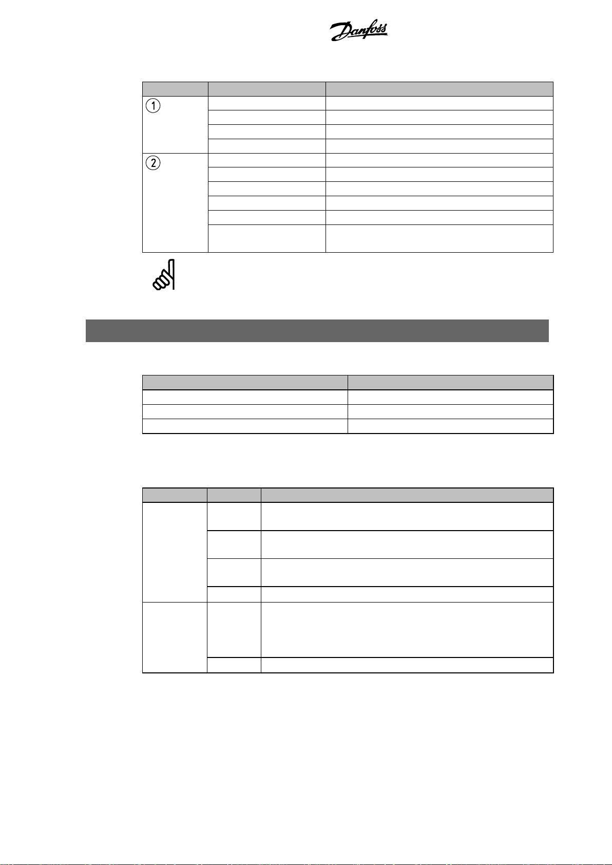
3. Configuration
The DeviceNet Module is a Group 2 slave device, using a predefined master/slave connection set.
I/O data is produced and consumed using polled I/O messaging.
The soft starter must be added to the DeviceNet manager project using the EDS file and
configuration/management software tool. This file is available from www.danfoss.com/drives. In
order to operate successfully, the correct EDS file must be used. An on-screen graphics bitmap
file (device.bmp) is also available.
4. Adjustment
The factory default settings for the rotary adjustment switches are:
Changes to the rotary switch settings take effect when the DeviceNet network is next powered
up.
MG17HA02 - VLT® is a registered Danfoss trademark 2
Page 3

MCD DeviceNet Module Instructions Connection
MCD 200
MCD 500
MCD 200
MCD 500 (Auto On mode)
17, 18: Stop
25, 18: Reset
MCD DeviceNet Module
MCD DeviceNet Module
Standard connection onto DeviceNet
network
Standard connection onto DeviceNet
network
N.B.!:
If MCD 500 parameter 3-2
Comms in Remote
is set to Disable Comms in Remote, the
starter will not accept start or stop commands from the serial network (the starter will
still accept reset commands and allow status monitoring).
5. Connection
MCD 200: For the MCD DeviceNet Module to accept serial commands, a link must be fitted across
terminals A1-N2 on the soft starter.
In order for the MCD 500 to accept commands from the serial network, the soft starter must be in
Auto On mode and links must be fitted to terminals 17, 18 and 25, 18.
In Hand On mode, the starter will not accept commands from the serial network but the starter's
status can still be monitored.
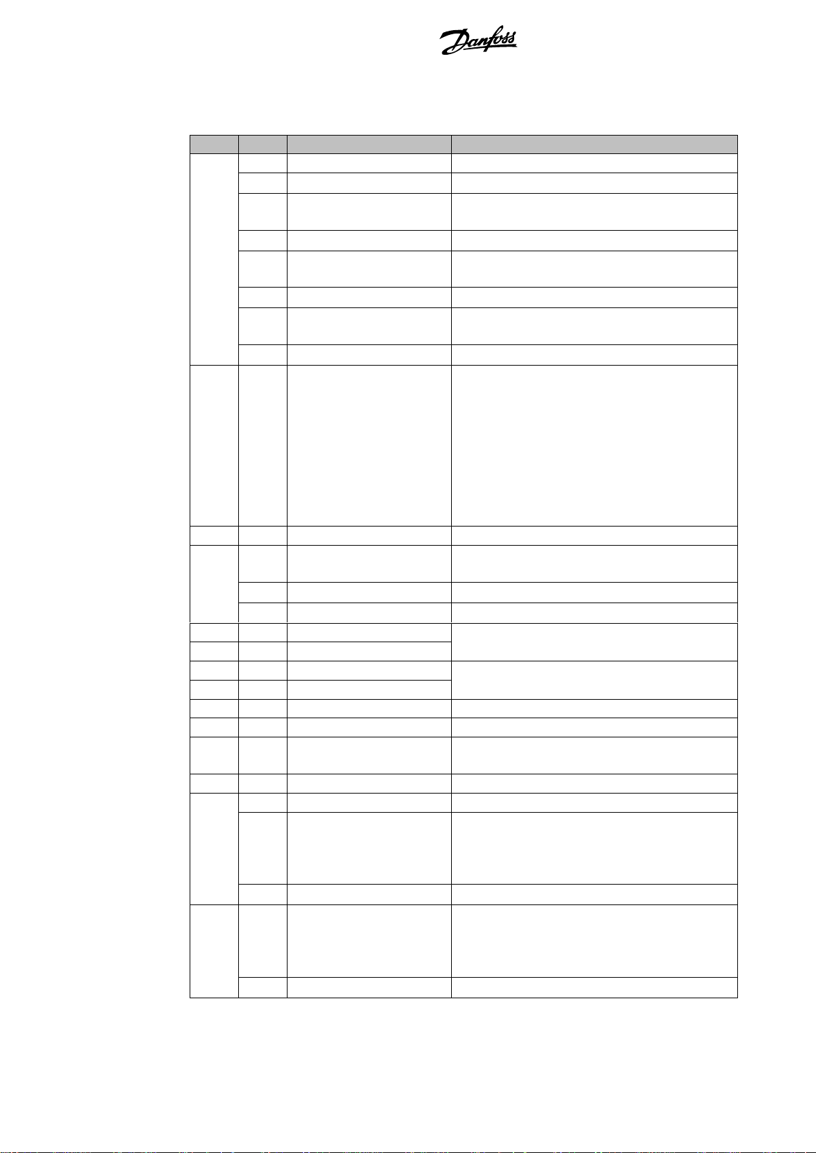
6. Module and Network LEDs
The Module LED indicates the condition of the power supply and module operation.
The Network LED indicates status of the communication link between the DeviceNet Module and
the network Master.
MG17HA02 – VLT® is a registered Danfoss trademark 3
Page 4
DeviceNet Polled I/O Structure MCD DeviceNet Module Instructions
LED
State
Description
(Module)
Off
Network power off
Green
Normal operation
Red
Unrecoverable fault
Red/Green flashing
Self Test mode
(Network)
Off
Duplicate MAC ID test has not been completed
Green flashing
Online but no connection with Master
Green
Online and allocated to a Master
Red flashing
One or more timed out I/O connections
Red
Failed communication between module and Master
Red/Green flashing
Communication faulted and received an Identity
communication faulted request
N.B.!:
When a communications failure occurs, the soft starter may trip if the Communication
Timeout parameter for the network is set greater than zero. When communication is
restored, the soft starter must be reset.
Parameter
Value
I/O connection type
Polled
Poll receive size
14 bytes
Poll transmit size
2 bytes
Byte
Bit
Function
0 0 0 = Stop command
1 = Start command
1
0 = Enable Start or Stop command
1 = Quick Stop (i.e. coast to stop) and disable Start command
2
0 = Enable Start or Stop command
1 = Reset command and disable Start command
3 to 7
Reserved
1
0 to 1
0 = Use soft starter remote input to select motor set
1 = Use primary motor set when starting 1
2 = Use secondary motor set when starting 1
3 =
Reserved
2 to 7
Reserved
7. DeviceNet Polled I/O Structure
Once the EDS file has been loaded, the DeviceNet Module must be added to the scanner list with
parameters shown in the following table:
Once the soft starter, module and Master have been set up, configured and powered up, the
Master will transmit 2 bytes of data to the module and receive 14 bytes of data from the module.
Master > Slave polled I/O output data is as follows:
1
Ensure that the programmable input is not set to Motor Set Select before using this function.
MG17HA02 - VLT® is a registered Danfoss trademark 4
Page 5
MCD DeviceNet Module Instructions DeviceNet Polled I/O Structure
Byte
Bit
Function
Value
0 0 Trip
1 = Tripped
1
Warning
1 = Warning
2
Running
0 = Unknown, not ready, ready to start or tripped
1 = Starting, running, stopping or jogging
3
Reserved
4
Ready
0 = Start or stop command not acceptable
1 = Start or stop command acceptable
5
Control from Net
1 = Always except in Program mode
6
Local/Remote
0 = Local control
1 = Remote control
7
At reference
1 = Running (full voltage at the motor)
1
0 to 7
Status
0 = Unknown (menu open)
2 = Starter not ready (restart delay, thermal delay
or run simulation)
3 = Ready to start (including warning state)
4 = Starting or running
5 = Soft stopping
7 = Trip
8 = Jog forward
9 = Jog reverse
2
0 to 7
Trip/Warning code
See trip code table.
3 0 Initialised
1 = Phase sequence bit is valid (bit 1) after 1st
start
1
Phase sequence
1 = Positive phase sequence detected
2 to 7
Reserved
4 1
0 to 7
Motor current (low byte)
Current (A)
5 1
0 to 7
Motor current (high byte)
6 0 to 7
Current %FLC (low byte)
Current as a percentage of soft starter FLC setting
(%)
7
0 to 7
Current %FLC (high byte)
8
0 to 7
% Motor 1 temperature
Motor 1 thermal model
9
0 to 7
% Motor 2 temperature
Motor 2 thermal model
10
0 to 7
% Power factor
Percentage power factor
(100 = power factor of 1)
11
0 to 7
Power (low byte)
Power low byte, scaled by power scale
12
0 to 3
Power (high nibble)
Power high nibble, scaled by power scale
4 to 5
Power scale
0 = Multiply power by 10 to get W
1 = Multiply power by 100 to get W
2 = Power (kW)
3 = Multiply power by 10 to get kW
6 to 7
Reserved
13
0 to 3
Digital Input state
0 = Start (0 = open, 1 = closed)
1 = Stop
2 = Reset
3 = Input A
4 to 7
Reserved
Slave > Master polled I/O input data is as follows:
1
For models MCD5-0428C and smaller this value will be 10 times greater than the value displayed
on the LCP.
MG17HA02 – VLT® is a registered Danfoss trademark 5
Page 6
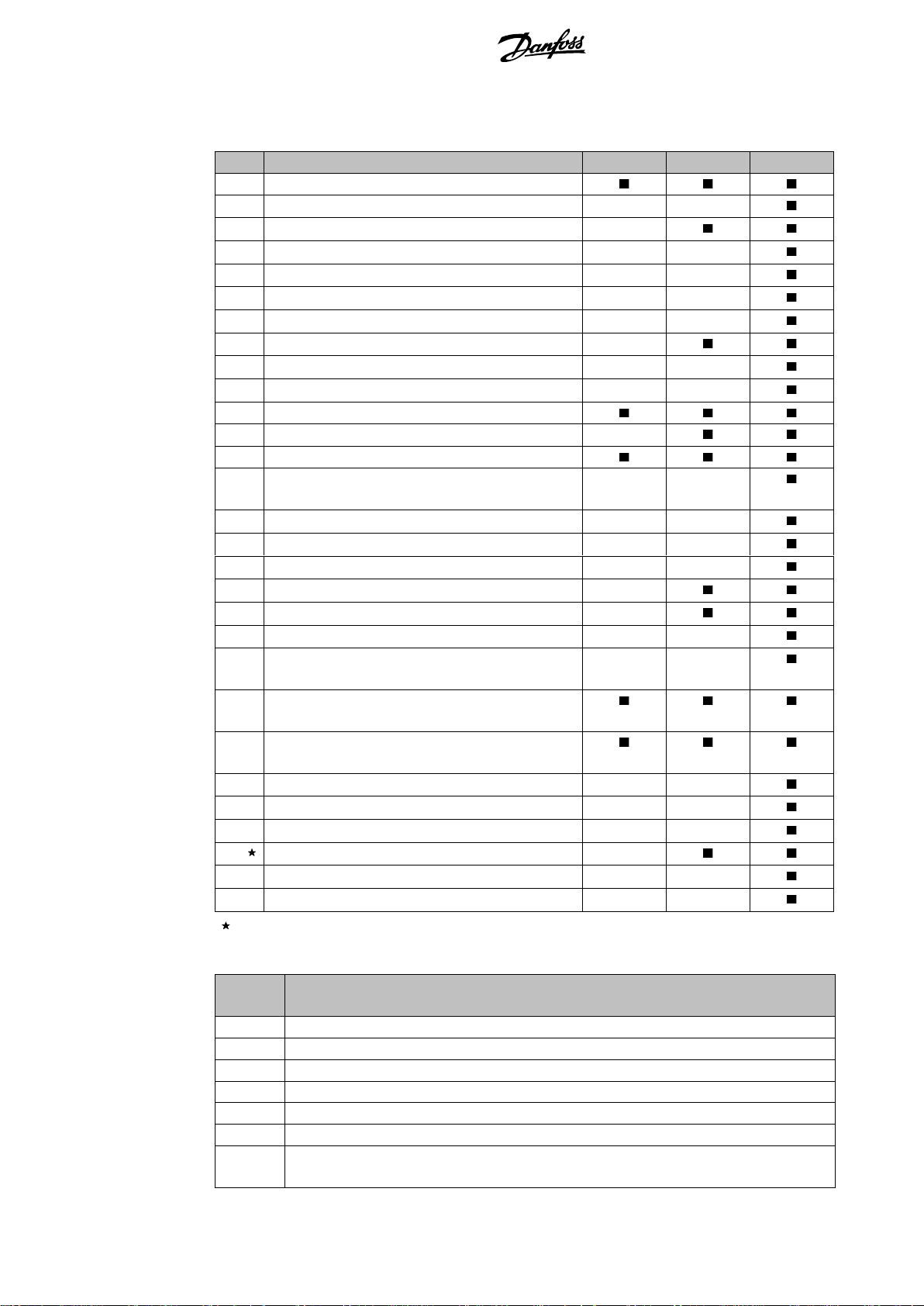
DeviceNet Polled I/O Structure MCD DeviceNet Module Instructions
Code
Trip Type
MCD 201
MCD 202
MCD 500
0
No trip
11
Input A trip
20
Motor overload (thermal model)
21
Heatsink overtemperature
23
L1 phase loss
24
L2 phase loss
25
L3 phase loss
26
Current imbalance
28
Instantaneous overcurrent
29
Undercurrent
50
Power loss/Power circuit
54
Phase sequence
55
Frequency (Mains supply)
60
Unsupported option (function not available in
inside delta)
61
FLC too high (FLC out of range)
62
Parameter out of Range
70
Miscellaneous
75
Motor thermistor
101
Excess start time
102
Motor connection
104
Internal fault x (where x is the fault code detailed
in the table below).
113
Starter communication (between module and soft
starter)
114
Network communication (between module and
network)
115
L1-T1 shorted
116
L2-T2 shorted
117
L3-T3 shorted
119
Time-overcurrent (Bypass overload)
121
Battery/clock
122
Thermistor circuit
Internal
fault
Message displayed on the LCP
70 ~ 72
Current Read Err Lx
73
Power On in Simulation mode
74 ~ 76
Motor connection Tx
77 ~ 79
Firing fail SCRx
80 ~ 82
VZC Fail Px
83
Low Control Volts
84 ~ 98
Internal fault X
Contact your local supplier with the fault code (X).
7.1.1. Trip Codes
For MCD 500, time-overcurrent protection is only available on internally bypassed models.
The table below details the internal fault code associated with trip code 104.
MG17HA02 - VLT® is a registered Danfoss trademark 6
Page 7

MCD DeviceNet Module Instructions Parameter Object
Detail
Value (Hex)
Comment
Class
0F
Parameter object address
Instance
1 ~ xxx
xxx = maximum soft starter parameter number
Attribute ID
01
Always 0x01
Get Service
0E
Read single soft starter parameter value
Set Service
10
Write single soft starter parameter value
N.B.!:
Only available on MCD 500 soft starters. For parameter details, see the soft starter
User Manual.
8. Parameter Object
The DeviceNet Module supports parameter objects through explicit messaging. Soft starter
parameters can be uploaded (written) and downloaded (read) using DeviceNet management
software. When the DeviceNet Module is powered up, it automatically obtains parameter
information from the soft starter.
MG17HA02 – VLT® is a registered Danfoss trademark 7
Page 8

Specifications MCD DeviceNet Module Instructions
È710-02937-00KrËÍ
9. Specifications
Enclosure
Dimensions ........................................................... 40 mm (W) x 166 mm (H) x 90 mm (D)
Weight .................................................................................................................. 250 g
Protection ............................................................................................................... IP20
Mounting
Spring-action plastic mounting clips (x 2)
Connections
Soft starter ....................................................................................... 6-way pin assembly
Network ..................................... 5-way male and unpluggable female connector (supplied)
Maximum cable size .......................................................................................... 2.5 mm2
Contacts ......................................................................................................... Gold flash
Settings
Node address (MAC ID)
Setting ............................................................................................. Rotary switches
Range ............................................................................. 0 to 63 (63, factory default)
Data rate
Setting ................................................................................................ Rotary switch
Options ............................................. 125 kB, 250 kB, 500 kB (125 kB, factory default)
Power
Consumption
steady state ................................................................................... 19 mA at 25 VDC
........................................................................................................ 31 mA at 11 VDC
in-rush (at 24 VDC) .............................................................. 1.8 A maximum for 2 ms
Galvanically isolated
Certification
CE ....................................................................................................... IEC 60947-4-2
MG17HA02 - VLT® is a registered Danfoss trademark 8
 Loading...