

Installation Guide
Modbus TCP Card
VLT® Soft Starter MCD 600
vlt-drives.danfoss.com


Modbus TCP Card
Installation Guide
Contents
1
Safety 5
1.1
Disclaimer 5
Warnings 5
1.2
2
Introduction 6
2.1
Product Design 6
2.2
Compatibility 6
2.3
Network Connection 6
3
Installation 7
3.1
Installing the Expansion Card 7
3.2
Network Connections 7
Ethernet Ports 7
3.2.1
Cables 7
3.2.2
Contents
3.2.3
EMC Precautions 7
3.3
Network Establishment 7
3.4
Addressing 7
4
Device Configuration 8
4.1
Before Configuring the Device 8
4.2
Configuration Methods 8
4.3
Parameters for Configuring Network Settings 8
4.4
Enabling Network Control 8
4.5
On-board Web Server 9
4.5.1
Connect to the Device 9
4.5.2
Manage Users and Passwords 10
4.5.2.1
4.5.2.2
4.5.3
Configuring the IP Address 11
4.5.4
Configure IoT Settings 11
4.5.4.1
Adding a User 10
Deleting a User 10
Configuring MQTT Settings 12
4.5.4.2
4.6
Scanning the Network 13
4.6.1
Identifying the Device with Ethernet Device Configuration Tool 13
5
PLC Configuration 15
5.1
Configuration Requirements for PLC 15
Configuring OPC UA Settings 13
AN353424224484en-000101/130R0946 | 3Danfoss A/S © 2020.12

Modbus TCP Card
Installation Guide
6
Operation 16
Requirements for Successful Operation 16
6.1
6.2
Device Classification 16
Ensuring Safe and Successful Control 16
6.3
6.4
Feedback LEDs 16
7
Modbus Registers 17
7.1
Important Information 17
7.2
Command and Configuration Registers (Read/Write) 17
7.3
Parameter Management 17
7.3.1
Writing Parameters to the Soft Starter 18
7.4
Status Reporting Registers (Read Only) 18
7.5
Legacy Mode 20
7.5.1
Initializing Legacy Mode 20
7.5.2
Registers 20
Contents
7.6
Trip Codes 24
8
Network Design 26
8.1
Star Topology 26
8.2
Line Topology 26
8.3
Ring Topology 27
8.4
Combined Topologies 27
9
Specifications 29
9.1
Connections 29
9.2
Settings 29
9.3
Network 29
9.4
Power 29
9.5
Certification 29
AN353424224484en-000101/130R09464 | Danfoss A/S © 2020.12

Modbus TCP Card
Installation Guide
Safety
1 Safety
1.1 Disclaimer
The examples and diagrams in this manual are included solely for illustrative purposes. The information contained in this manual is
subject to change at any time and without prior notice. Responsibility or liability is never accepted for direct, indirect, or consequential damage resulting from the use or application of this equipment.
1.2 Warnings
W A R N I N G
SHOCK HAZARD
Attaching or removing accessories while the soft starter is connected to mains voltage may cause personal injury.
Before attaching or removing accessories, isolate the soft starter from mains voltage.
-
W A R N I N G
RISK OF PERSONAL INJURY AND EQUIPMENT DAMAGE
Inserting foreign objects or touching the inside of the soft starter while the expansion port cover is open may endanger person-
nel and can damage the soft starter.
Do not insert foreign objects in the soft starter with the port cover open.
-
Do not touch the inside of the soft starter with the port cover open.
-
AN353424224484en-000101 / 130R0946 | 5Danfoss A/S © 2020.12
Protocols
Modbus TCP
Industrial Ethernet via Modbus TCP
TCP
Transmission control protocol to connect to port 4000 of a PC
MQTT
Message queue telemetry transport
OPC UA
Open platform communications unified architecture
4/T2
READY RUN TRIP LOCAL
Exit
Reset
Menu
Store
2/T1 6/T3
1/L1 3/L2
5/L3
VLT
®
Soft Starter
1
2
4
3
5
e77ha805.10
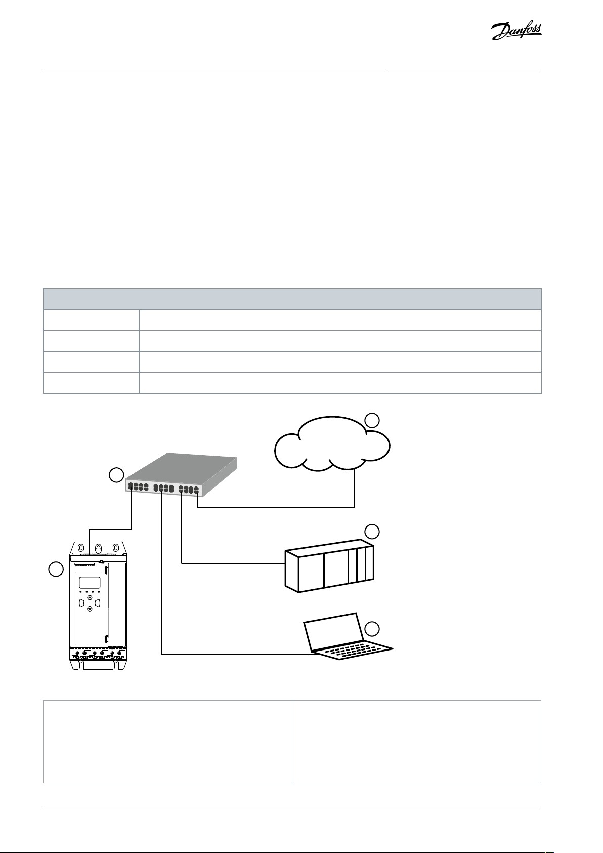
1
Soft starter
2
Network switch
3
IoT connection (MQTT/OPC UA)
4
Industrial Ethernet connection to programmable
logic controller
5
TCP connection to VLT® Motion Control Tool MCT
10. Refer to the VLT® Motion Control Tool MCT 10
Operating Guide for connection details.
Modbus TCP Card
Installation Guide
Introduction
2 Introduction
2.1 Product Design
The Modbus TCP Card allows the soft starter to connect to an Ethernet network and be controlled or monitored using an Ethernet
communication model.
Familiarity with Ethernet protocols and networks is required to operate the device successfully. For difficulties arising from using
this device with 3rd-party products, including PLCs, scanners, and commissioning tools, contact the relevant supplier.
2.2 Compatibility
This communication expansion card is suitable for use with VLT® Soft Starter MCD 600.
This Installation Guide is intended for use with version 2.x of the VLT® Soft Starter MCD 600 Modbus TCP Card. Version 1.x of the
Modbus TCP Card does not support custom users, TCP connection, or IoT operation.
2.3 Network Connection
Table 1: Supported Protocols
Illustration 1: Overview of Network Connections
AN353424224484en-000101 / 130R09466 | Danfoss A/S © 2020.12
1 2
e77ha739.10
Modbus TCP Card
Installation Guide
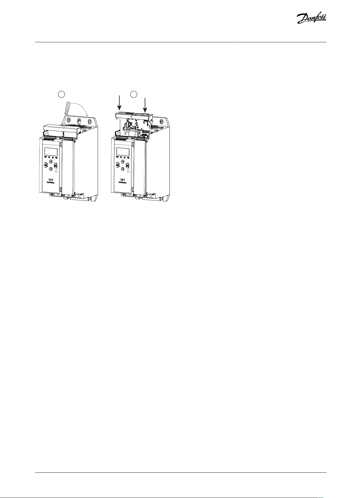
3 Installation
3.1 Installing the Expansion Card
Installation
Procedure
1.
Push a small flat-bladed screwdriver into the slot in the center of the expansion port cover and ease the cover away from
the soft starter.
2.
Align the card with the expansion port. Gently push the card along the guide rails until it clicks into the soft starter.
3.2 Network Connections
3.2.1 Ethernet Ports
The device has 2 Ethernet ports. If only 1 connection is required, either port can be used.
3.2.2 Cables
When connecting to the device, make sure that the cables are of 1 of the following categories:
•
Category 5
•
Category 5e
•
Category 6
•
Category 6e
3.2.3 EMC Precautions
To minimize electromagnetic interference, Ethernet cables should be separated from motor and mains cables by 200 mm (7.9 in).
If the Ethernet cable must cross motor or mains cables, the crossing should be at an angle of 90°.
3.3 Network Establishment
The controller must establish communications directly with each device before the device can participate in the network.
3.4 Addressing
Each device in a network is addressed using a MAC address and an IP address.
•
The device can be assigned a static IP address during configuration or can be configured to accept a dynamic IP address (via
DHCP).
•
The MAC address is fixed within the device and is printed on a label on the front of the device.
AN353424224484en-000101 / 130R0946 | 7Danfoss A/S © 2020.12

Parameter
Default
12-8 Gateway Address
192
12-9 Gateway Address 2
168
12-10 Gateway Address 3
0
12-11 Gateway Address 4
100
12-12 IP Address
192
12-13 IP Address 2
168
12-14 IP Address 3
0
12-15 IP Address 4
2
12-16 Subnet Mask
255
12-17 Subnet Mask 2
255
12-18 Subnet Mask 3
255
12-19 Subnet Mask 4
0
12-20 DHCP
Disable
12-21 Location ID
0
Modbus TCP Card
Installation Guide
Device Configuration
4 Device Configuration
4.1 Before Configuring the Device
N O T I C E
The error LED flashes whenever the device is receiving power but is not connected to a network. The error LED will flash occa-
sionally during the configuration process.
N O T I C E
At power-up, the communication card loads the IP address stored in the soft starter.
4.2 Configuration Methods
Network communication parameters for the communication card can be set via the soft starter or via the on-board web server.
•
The card uses a static IP address by default. To enable DHCP addressing, set parameter 12–20 DHCP to enable or change the
setting via the on-board web server.
•
The IP address can be set via the programmable parameters of the soft starter.
•
The web server can configure the IP address and messaging settings for MQTT/OPC UA operation.
4.3 Parameters for Configuring Network Settings
Use parameters 12-8 to 12-21 to configure the network address. The parameters can be set via the Main Menu, via the Setup Tools,
or by uploading a configuration file via USB Save & Load.
4.4 Enabling Network Control
If the reset input is active, the soft starter does not operate. If a reset switch is not required, use parameter 7-9 to set the reset
input to normally open or fit a link across terminals RESET, COM+ on the soft starter.
N O T I C E
AN353424224484en-000101 / 130R09468 | Danfoss A/S © 2020.12
e77ha807.10
Modbus TCP
Modbus TCP
MCD 600
e77ha814.10
Modbus TCP Card
Installation Guide
Device Configuration
Procedure
1.
Set parameter 1-1 Command Source to Network for the soft starter to accept commands from the Modbus TCP Card.
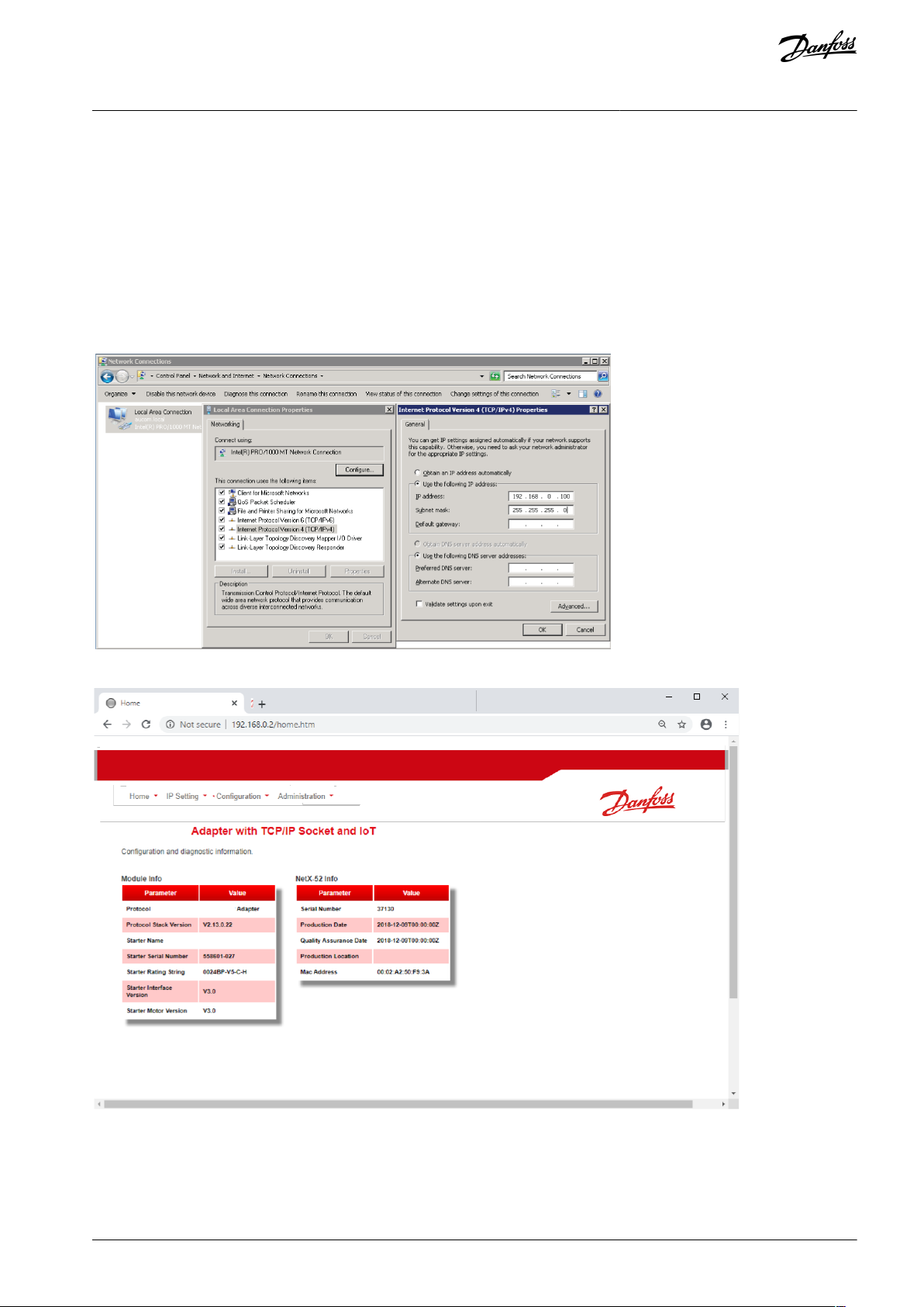
4.5 On-board Web Server
4.5.1 Connect to the Device
To configure settings using the on-board web server, the Modbus TCP Card must be installed in a soft starter, control power must
be available, and the card and computer must both be connected to the Ethernet network.
The computer must use a fixed IP address (not DHCP) and the same subnet mask as the card. The default IP address for the card is
192.168.0.2. The default subnet mask is 255.255.255.0.
Once connected, the web server reports basic information about the card and the soft starter.
AN353424224484en-000101 / 130R0946 | 9Danfoss A/S © 2020.12

1
2
3
5
6
e77ha808.10
4
Modbus TCP Card
Installation Guide
4.5.2 Manage Users and Passwords
N O T I C E
For security reasons, define a custom administrator ID and password. The default username and password are:
Username: danfoss_admin
-
Password: danfoss_admin
-
N O T I C E
Version 1.x of the Modbus TCP Card does not support custom users.
The Modbus TCP Card supports multiple users and levels of privilege.
•
Users can view the home screen and IP settings.
•
Supervisors can view the home screen and IP settings, and they can change configuration settings.
•
Administrators can view the home screen, change configuration settings, and add or delete users.
4.5.2.1 Adding a User
Device Configuration
Procedure
1.
Connect to the web server and click Administration.
2.
Click Create new user.
Enter the new username and password.
3.
4.
Click Create an account.
Set privileges (user, supervisor, administrator) as appropriate.
5.
6.
Click Save changes.
4.5.2.2 Deleting a User
Procedure
1.
Connect to the web server and click Administration.
2.
3.
Select the required entry in the user list and click Delete.
Click Delete again to confirm the action.
AN353424224484en-000101 / 130R094610 | Danfoss A/S © 2020.12

1
2
3
e77ha806.10
Modbus TCP Card
Installation Guide
Device Configuration
4.5.3 Configuring the IP Address
N O T I C E
For version 1.x of the Modbus TCP Card, changes made via the web server are not stored in the soft starter and will be lost when
control power is cycled.
Procedure
1.
Connect to the web server and click IP Setting.
2.
Edit settings as required. To enable DHCP addressing, tick the DHCP checkbox.
3.
Click Submit to send the new settings to the device.
4.5.4 Configure IoT Settings
The Modbus TCP Card supports soft starter status monitoring via IoT. The card cannot control or program the soft starter.
N O T I C E
Version 1.x of the Modbus TCP Card does not support IoT operation.
AN353424224484en-000101 / 130R0946 | 11Danfoss A/S © 2020.12

e77ha810.10
Modbus TCP Card
Installation Guide
4.5.4.1 Configuring MQTT Settings
Device Configuration
Procedure
1.
Connect to the web server and click Configuration.
2.
Select MQTT Client.
3.
Tick the Enable checkbox to enable MQTT client operation.
4.
Click Connection and configure the settings as required.
5.
Click Connections⇒Actions to select which information the card should publish.
6.
Click Submit to save all settings in the card.
The MQTT client is enabled by default.
AN353424224484en-000101 / 130R094612 | Danfoss A/S © 2020.12

e77ha813.10
Modbus TCP Card
Installation Guide
4.5.4.2 Configuring OPC UA Settings
Device Configuration
Procedure
1.
Connect to the web server and click Configuration.
2.
Select OPC UA Server.
3.
Tick the Enable checkbox to enable OPC UA client operation.
The OPC UA client is enabled by default.
4.
Click Server Configuration and configure the settings as required.
5.
Select Actions to select the actions for different object instances.
6.
Click Submit to save all settings in the card.
4.6 Scanning the Network
If there is no connection to the web server and the soft starter cannot be accessed physically, use the Ethernet Device Configuration
Tool to scan the network and identify the device. Changes made via the Ethernet Device Configuration Tool cannot be stored permanently in the device and will be lost when the control power is cycled.
Download the Ethernet Device Configuration Tool from
www.danfoss.com under the sections Services/PC-tools.
N O T I C E
If the PC has a firewall enabled, add the tool to the list of authorized programs.
4.6.1 Identifying the Device with Ethernet Device Configuration Tool
Procedure
1.
Start the Ethernet Device Configuration Tool.
2.
Click Search Devices.
AN353424224484en-000101 / 130R0946 | 13Danfoss A/S © 2020.12

e77ha641.10
Modbus TCP Card
Installation Guide
Device Configuration
The software searches for connected devices.
3.
Use the IP address to connect to the device via the web server.
AN353424224484en-000101 / 130R094614 | Danfoss A/S © 2020.12

e77ha632.10
Modbus TCP Card
Installation Guide
5 PLC Configuration
5.1 Configuration Requirements for PLC
The PLC must be configured to map registers within the communication card to addresses within the PLC.
The device must be configured directly in the PLC. No extra files are required.
PLC Configuration
AN353424224484en-000101 / 130R0946 | 15Danfoss A/S © 2020.12

Port 1 Port 2
Keypad
LINK 2
TX/RX2
LINK 1
TX/RX1
ERROR
STATUS
e77ha742.10
LED name
LED state
Description
Error
Off
No error.
Flashing
System error.
On
Communication error.
Status
Off
The device is not powered up.
Slow flash
The device is ready but not configured.
Fast flash
Communication has been established.
Link x
Off
No network connection.
On
Connected to a network.
TX/RX x
Flashing
Transmitting or receiving data.
Off
No network connection.
Modbus TCP Card
Installation Guide
Operation
6 Operation
6.1 Requirements for Successful Operation
The Modbus TCP Card must be controlled by a Modbus client (such as a PLC), which complies with the Modbus Protocol Specification. For successful operation, the client must also support all functions and interfaces described in this manual.
N O T I C E
The available features and parameter details may vary according to the model and software version of the soft starter. Refer to
the VLT® Soft Starter MCD 600 Operating Guide for details of parameters and supported features.
6.2 Device Classification
The Modbus TCP Card is a Modbus server and must be managed by a Modbus client over Ethernet.
6.3 Ensuring Safe and Successful Control
Data written to the device remains in its registers until the data is overwritten or the device is reinitialized. If the soft starter is controlled via parameter 7-1 Command Override or is disabled via the reset input (terminals RESET, COM+), fieldbus commands should
be cleared from the registers. If a command is not cleared, it is re-sent to the soft starter once fieldbus control resumes.
6.4 Feedback LEDs
Table 2: LED Descriptions
AN353424224484en-000101 / 130R094616 | Danfoss A/S © 2020.12

Register
Description
Bits
Details
40001
Command (single write)
0–7
To send a command to the soft starter, write the required value:
00000000 = Stop
00000001 = Start
00000010 = Reset
00000100 = Quick stop (coast to stop)
00001000 = Forced communication trip
00010000 = Start using Parameter Set 1
00100000 = Start using Parameter Set 2
01000000 = Reserved
10000000 = Reserved
8–14
Reserved
15
Must = 1
40002
Reserved
40003
Reserved
40004
Reserved
40005
Reserved
40006
Reserved
40007
Reserved
40008
Reserved
40009–40xxx
Parameter management (single/multiple read or multiple write)
0–15
Manage soft starter programmable parameters.
Modbus TCP Card
Installation Guide
Modbus Registers
7 Modbus Registers
7.1 Important Information
N O T I C E
The available features and parameter details may vary according to the model and software version of the soft starter. Refer to
the VLT® Soft Starter MCD 600 Operating Guide for details of parameters and supported features.
N O T I C E
All references to registers mean the registers within the communication card unless otherwise stated.
7.2 Command and Configuration Registers (Read/Write)
Table 3: Details of Command and Configuration Registers
7.3 Parameter Management
Parameters can be read from and written to the soft starter. When writing parameters to the soft starter, every parameter is updated
to match the values in the PLC.
While parameters are being written, the soft starter cannot start/stop the motor.
The Modbus TCP protocol limits read/write operations to a maximum of 123 registers at one time. The registers must be consecutive.
N O T I C E
AN353424224484en-000101 / 130R0946 | 17Danfoss A/S © 2020.12

Register
Description
Bits
Details
30003
Reserved
30004
Reserved
30005
Reserved
30006
Reserved
30007
Reserved
30008
Reserved
30600
Product information
0–5
Binary protocol version
6–8
Parameter list major version
9–15
Product type code: 15 = MCD 600
30601
Model number
0–7
Reserved
8–15
Soft starter model ID
30602
Reserved
30603
Reserved
30604
Starter state
0–4
0 = Reserved
1 = Ready
2 = Starting
3 = Running
4 = Stopping
5 = Not ready (restart delay, restart temperature check, run simulation,
reset input is open)
6 = Tripped
7 = Programming mode
Modbus TCP Card
Installation Guide
To avoid loss of communications due to an unintentional change of network configuration, write the network address parameter
settings before writing start/stop parameter settings.
Modbus Registers
7.3.1 Writing Parameters to the Soft Starter
N O T I C E
For reliable operation, the parameter block containing network configuration settings must be written first.
Procedure
1.
Configure all soft starter parameter values in the PLC as required, including IP address, gateway address, subnet mask, and
DHCP configuration.
2.
Write the parameter block that includes the network parameter settings from the PLC to the soft starter.
3.
Write the other parameter blocks from the PLC to the soft starter until all parameter values have been written.
7.4 Status Reporting Registers (Read Only)
N O T I C E
For models MCD6-0063B and smaller (soft starter model ID 1~4), the current reported via communications registers is 10 times
greater than the actual value.
Table 4: Description of Read Registers
AN353424224484en-000101 / 130R094618 | Danfoss A/S © 2020.12

Register
Description
Bits
Details
8 = Jog forward
9 = Jog reverse
5
1 = Warning
6
0 = Uninitialized
1 = Initialized
7
Command source
0 = Remote LCP, Digital Input, Clock
1 = Network
8
Reserved
9
0 = Negative phase sequence
1 = Positive phase sequence
10–15
Reserved
30605
Current
0–13
Average rms current across all 3 phases
14–15
Reserved
30606
Current
0–9
Current (% motor FLC)
10–15
Reserved
30607
Motor temperature
0–7
Motor thermal model (%)
8–15
Reserved
30608
Power
0–11
Power
12–13
Power scale
0 = Multiply power by 10 to get W
1 = Multiply power by 100 to get W
2 = Power (kW)
3 = Multiply power by 10 to get kW
14–15
Reserved
30609
% Power factor
0–7
100% = power factor of 1
8–15
Reserved
30610
Voltage
0–13
Average rms voltage across all 3 phases
14–15
Reserved
30611
Current
0–13
Phase 1 current (rms)
14–15
Reserved
30612
Current
0–13
Phase 2 current (rms)
14–15
Reserved
30613
Current
0–13
Phase 3 current (rms)
14–15
Reserved
Modbus TCP Card
Installation Guide
Modbus Registers
AN353424224484en-000101 / 130R0946 | 19Danfoss A/S © 2020.12

Register
Description
Bits
Details
30614
Voltage
0–13
Phase 1 voltage
14–15
Reserved
30615
Voltage
0–13
Phase 2 voltage
14–15
Reserved
30616
Voltage
0–13
Phase 3 voltage
14–15
Reserved
30617
Parameter list version number
0–7
Parameter list minor revision
8–15
Parameter list major version
30618
Digital input state
0–15
For all inputs, 0 = open, 1 = closed (shorted)
0 = Start/Stop
1 = Reserved
2 = Reset
3 = Input A
4 = Input B
5–15 = Reserved
30619
Trip code
0–15
See the chapter Trip Codes.
8–15
Reserved
30620–30631
Reserved
Modbus TCP Card
Installation Guide
Modbus Registers
The reset input is normally closed by default. If parameter 7-9 Reset/Enable Logic is set to normally open, the reported state is
inverted (0 = closed, 1 = open).
7.5 Legacy Mode
The Modbus TCP Card can also operate in Legacy Mode, which uses the same registers as the clip-on Modbus RTU Module supplied
by Danfoss for use with older soft starters. Some registers differ from those specified in the Modbus protocol specification.
7.5.1 Initializing Legacy Mode
If the card has been operating in Standard Mode, it must be reset before communicating in Legacy Mode. To initialize the card for
Legacy Mode, either:
•
cycle control power, or
•
reset register 40001 to 0 (write 0 to bits 0–15).
7.5.2 Registers
For models MCD6-0063B and smaller, the current reported via communications registers is 10 times greater than the actual value.
Legacy Mode reports read-only status information in registers 40003 onwards to match the register definitions of the clip-on
Modbus Module. Identical data is also available via registers 30003 onwards.
N O T I C E
N O T I C E
N O T I C E
AN353424224484en-000101 / 130R094620 | Danfoss A/S © 2020.12

Register
Description
Bits
Details
40001
Reserved
40002
Command (single write)
0–2
To send a command to the starter, write the required value:
1 = Start
2 = Stop
3 = Reset
4 = Quick stop (coast to stop)
5 = Forced communication trip
6 = Start using Parameter Set 1
7 = Start using Parameter Set 2
3–15
Reserved
40003
Soft starter state
0–3
1 = Ready
2 = Starting
3 = Running
4 = Stopping (including braking)
5 = Restart delay (including temperature check)
6 = Tripped
7 = Programming mode
8 = Jog forward
9 = Jog reverse
4
1 = Positive phase sequence (only valid if bit 6 = 1)
5
1 = Current exceeds FLC
6
0 = Uninitialized
1 = Initialized
7–15
Reserved
40004
Reserved
40005
Motor current
0–7
Average 3-phase motor current (A)
8–15
Reserved
40006
Motor temperature
0–7
Motor thermal model (%)
8–15
Reserved
40007
Reserved
40008
Reserved
40009–40xxx
Parameter management (single or multiple read/ write)
0–7
Manage soft starter programmable parameters. See the VLT® Soft
Starter MCD 600 Operating Guide for a complete parameter list.
8–15
Reserved
40600
Version
0–5
Binary protocol version
6–8
Parameter list version number
9–15
Product type code:
Modbus TCP Card
Installation Guide
Table 5: Description of Registers in Legacy Mode
Modbus Registers
AN353424224484en-000101 / 130R0946 | 21Danfoss A/S © 2020.12

Register
Description
Bits
Details
15 = MCD 600
40601
Model number
0–7
Reserved
8–15
Soft starter model ID
40602
Reserved
40603
Reserved
40604
Starter state
0–4
0 = Reserved
1 = Ready
2 = Starting
3 = Running
4 = Stopping
5 = Not ready (restart delay, restart temperature check, run simulation,
reset input is open)
6 = Tripped
7 = Programming mode
8 = Jog forward
9 = Jog reverse
5
1 = Warning
6
0 = Uninitialized
1 = Initialized
7
Command source
0 = Remote LCP, Digital Input, Clock
1 = Network
8
Reserved
9
0 = Negative phase sequence
1 = Positive phase sequence
10–15
Reserved
40605
Current
0–13
Average rms current across all 3 phases
14–15
Reserved
40606
Current
0–9
Current (% motor FLC)
10–15
Reserved
40607
Motor temperature
0–7
Motor thermal model (%)
8–15
Reserved
40608
Power
0–11
Power
12–13
Power scale
0 = Multiply power by 10 to get W
1 = Multiply power by 100 to get W
2 = Power (kW)
3 = Multiply power by 10 to get kW
Modbus TCP Card
Installation Guide
Modbus Registers
AN353424224484en-000101 / 130R094622 | Danfoss A/S © 2020.12

Register
Description
Bits
Details
14–15
Reserved
40609
% Power factor
0–7
100% = power factor of 1
8–15
Reserved
40610
Voltage
0–13
Average rms voltage across all 3 phases
14–15
Reserved
40611
Current
0–13
Phase 1 current (rms)
14–15
Reserved
40612
Current
0–13
Phase 2 current (rms)
14–15
Reserved
40613
Current
0–13
Phase 3 current (rms)
14–15
Reserved
40614
Voltage
0–13
Phase 1 voltage
14–15
Reserved
40615
Voltage
0–13
Phase 2 voltage
14–15
Reserved
40616
Voltage
0–13
Phase 3 voltage
14–15
Reserved
40617
Parameter list version number
0–7
Parameter list minor revision
8–15
Parameter list major version
40618
Digital input state
0–15
For all inputs, 0 = open, 1 = closed (shorted)
0 = Start/Stop
1 = Reserved
2 = Reset
3 = Input A
4 = Input B
5–15 = Reserved
40619
Trip code
0–7
See the chapter Trip Codes
8–15
Reserved
40620–40631
Reserved
Modbus TCP Card
Installation Guide
Modbus Registers
The reset input is normally closed by default. If parameter 7-9 Reset/Enable Logic is set to normally open, the reported state is
inverted (0 = closed, 1 = open).
N O T I C E
AN353424224484en-000101 / 130R0946 | 23Danfoss A/S © 2020.12

Code
Description
255
No trip
1
Excess start time
2
Motor overload
3
Motor thermistor
4
Current imbalance
5
Frequency
6
Phase sequence
7
Overcurrent
8
Power loss
9
Undercurrent
10
Heat sink overtemperature
11
Motor connection
12
Input A trip
13
FLC too high
14
Unsupported option (function not available in inside delta)
15
Communications card fault
16
Network communication
18
Overvoltage
19
Undervoltage
23
Parameter out of range
20
Motor overload
24
Input B trip
26
L1 phase loss
27
L2 phase loss
28
L3 phase loss
29
L1-T1 shorted
30
L2-T2 shorted
31
L3-T3 shorted
33
Time-overcurrent (bypass overload)
34
SCR overtemperature
35
Battery/clock
36
Thermistor circuit
Modbus TCP Card
Installation Guide
7.6 Trip Codes
Modbus Registers
AN353424224484en-000101 / 130R094624 | Danfoss A/S © 2020.12

Code
Description
47
Overpower
48
Underpower
56
LCP disconnected
57
Zero speed detect
58
SCR Itsm
59
Instantaneous overcurrent
60
Rating capacity
70
Current Read Err L1
71
Current Read Err L2
72
Current Read Err L3
74
Motor connection T1
75
Motor connection T2
76
Motor connection T3
77
Firing fail P1
78
Firing fail P2
79
Firing fail P3
80
VZC fail P1
81
VZC fail P2
82
VZC fail P3
83
Low control volts
84–96
Internal fault x. Contact the local supplier with the fault code (x).
Modbus TCP Card
Installation Guide
Modbus Registers
AN353424224484en-000101 / 130R0946 | 25Danfoss A/S © 2020.12

e77ha628.10
e77ha629.10
Modbus TCP Card
Installation Guide
8 Network Design
8.1 Star Topology
In a star network, all controllers and devices connect to a central network switch.
Network Design
Illustration 2: Example of Star Topology
8.2 Line Topology
In a line network, the controller connects directly to 1 port of the 1st card. The 2nd Ethernet port connects to another card, which in
turn connects to another device until all devices are connected.
Illustration 3: Example of Line Topology
N O T I C E
The device has an integrated switch to allow data to pass through in line topology. The device must be receiving control power
from the soft starter for the switch to operate.
N O T I C E
If the connection between 2 devices is interrupted, the controller cannot communicate with devices after the interruption point.
AN353424224484en-000101 / 130R094626 | Danfoss A/S © 2020.12

e77ha630.10
Modbus TCP Card
Installation Guide
Network Design
N O T I C E
Each connection adds a delay to the communication with the next device. The maximum number of devices in a line network is
32. Exceeding this number may reduce the reliability of the network.
8.3 Ring Topology
In a ring topology network, the controller connects to the 1st card via a network switch. The 2nd Ethernet port of the card connects
to another device, which in turn connects to another device until all devices are connected. The final device connects back to the
switch.
The device supports beacon-based ring node configuration.
Illustration 4: Example of Ring Topology
N O T I C E
The network switch must support loss of line detection.
8.4 Combined Topologies
A single network can include both star and line components.
AN353424224484en-000101 / 130R0946 | 27Danfoss A/S © 2020.12

e77ha631.10
Modbus TCP Card
Installation Guide
Network Design
Illustration 5: Example of Combined Topologies
AN353424224484en-000101 / 130R094628 | Danfoss A/S © 2020.12

Soft starter
6-way pin assembly
Contacts
Gold flash
Network
RJ45
IP address
Automatically assigned, configurable
Device name
Automatically assigned, configurable
Link speed
10 Mbps, 100 Mbps (auto-detect)
Full duplex
Auto crossover
Consumption (steady state, maximum)
35 mA@24 V DC
Reverse polarity protected
Galvanically isolated
RCM
IEC 60947-4-2
CE
EN 60947-4-2
Modbus TCP Card
Installation Guide
9 Specifications
9.1 Connections
9.2 Settings
9.3 Network
9.4 Power
Specifications
9.5 Certification
AN353424224484en-000101 / 130R0946 | 29Danfoss A/S © 2020.12

Danfoss A/S
Ulsnaes 1
DK-6300 Graasten
vlt-drives.danfoss.com
Danfoss can accept no responsibility for possible errors in catalogs, brochures and other printed material. Danfoss reserves the right to alter its products without notice. This
also applies to products already on order provided that such alterations can be made without subsequential changes being necessary in specifications already agreed. All
trademarks in this material are property of the respective companies. Danfoss and the Danfoss logotype are trademarks of Danfoss A/S. All rights reserved.
*130R0946*
Danfoss A/S © 2020.12
AN353424224484en-000101 / 130R0946
*M0025601*
 Loading...