

Page 1
Installation Instructions
VLT® Line Filter MCC 107 EMC Filter Series
®
VLT
Midi Drive FC 280 (K1–K3)
These instructions provide technical and installation
information for the MCC 107 EMC lter series.
Only Danfoss qualied personnel is allowed to install this
equipment. The personnel must be familiar with the
instructions and safety measures described in the
®
Midi Drive FC 280 Operating Guide.
VLT
Ordering Numbers
Description Ordering number
®
MCC 107 for VLT
MCC 107 for VLT
MCC 107 for VLT
MCC 107 for VLT
MCC 107 for VLT
Tab le 1.1 Ordering Num be rs
1) K1–K3 is 3 enclosure sizes of VLT
S2 represents 1x200–240 V. T4 represents 3x380–480 V.
®
Midi Drive FC 280 T4, only H1 version is optimized to operate
For VLT
with the EMC lters installed.
Midi Drive FC 280 K1S2
®
Midi Drive FC 280 K2S2
®
Midi Drive FC 280 K1T4
®
Midi Drive FC 280 K2T4
®
Midi Drive FC 280 K3T4
®
1)
1)
1)
1)
1)
Midi Drive FC 280.
134B5466
134B5467
134B5463
134B5464
134B5465
Tool s R equi red
Safety Instructions
WARNING
DISCHARGE TIME
The frequency converter contains DC-link capacitors which
can remain charged even when the frequency converter is
not powered. High voltage can be present even when the
warning LED indicator lights are
specied time after power has been removed before
performing service or repair work can result in death or
serious injury.
Stop the motor.
•
Disconnect AC mains and remote DC-link supplies,
•
including battery back-ups, UPS, and DC-link
connections to other frequency converters.
Disconnect or lock PM motor.
•
Wait for the capacitors to discharge fully. The
•
minimum waiting time is specied in Ta bl e 1 .2.
Before performing any service or repair work, use
•
an appropriate voltage measuring device to make
sure that the capacitors are fully discharged.
Failure to wait the
o.
SZS 0.6x3.5 mm slot screwdriver for EMC lter
•
terminals.
Voltage [V]
200–240 0.37–2.2 (0.5–3) 4
380–480 0.37–7.5 (0.5–10) 4
Tab le 1.2 Discharg e Time
Power range
[kW (hp)]
Minimum waiting time
(minutes)
Danfoss A/S © 05/2017, Rev. 02, All rights reserved. MI07L102
Page 2
Installation Instructions
®
VLT
Line Filter MCC 107 EMC Filter Series
®
Midi Drive FC 280 (K1–K3)
VLT
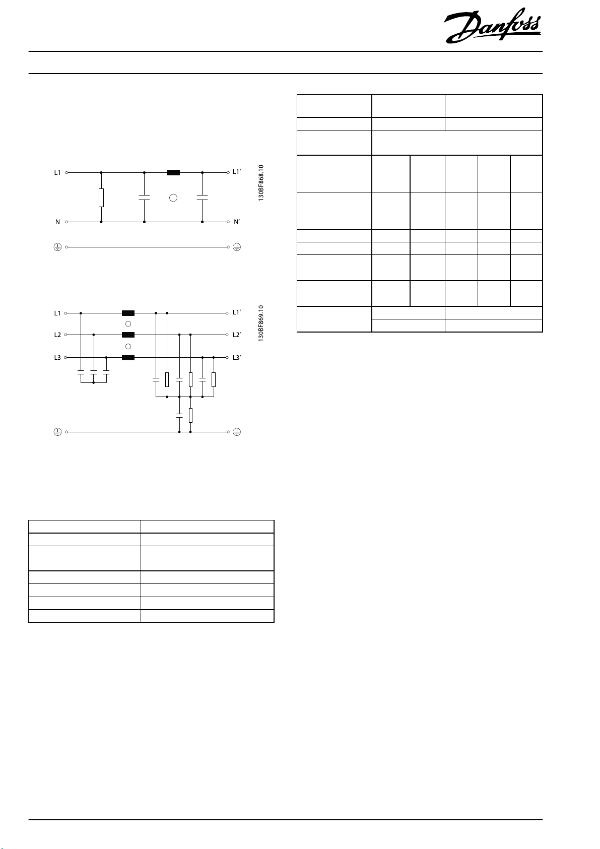
Product Overview
Illustration 1.1 and Illustration 1.2 show the typical circuit
diagram of the EMC
Illustration 1.1 Circuit Diagram for 1-phase EMC Filter
lters.
Number of phases 1 3
Rated voltage [V ] 1x200–240 ±10% 3x380–480 ±10%
Rated frequency
[Hz]
50–60
EMC lter
ordering number
466 467 463 464 465
134B5xxx
Frequ ency
converter
K1S2 K2S2 K1T4 K2T4 K3T4
enclosure size
Rated current in [A] 11 15 5 11.6 16
Power loss [W] 6.0 9.1 3.8 9.4 12.4
Maximum leakage
current [mA]
1)
Maximum leakage
current [mA]
2)
High-voltage test
[V-]
0 0 187 124.8 124.8
0 0 19.5 13 13
2100 Line-neutral 2780 Line-line
2700 Line-case 2780 Line-case
Table 1. 4 Tech nical Dat a
1) Calculated for maximum line voltage tolerance, by loss of 2 phases
(typical @ 50 Hz).
2) Maximum allowed voltage uctuation in accordance with IEC 38
±10%.
Illustration 1.2 Circuit Diagram for 3-phase EMC Filter
Tabl e 1.3 and Ta ble 1.4 show the operating conditions and
technical data of the EMC lters.
Enclosure protection rating IP20
°
Ambient temperature 50
Climatic category
25/085/21 [in accordance with EN
60068-1]
Type of cooling Ambient natural air
Operating conditions Continuous
°
Derating > 50
C (122 °F) -3% / K
Derating > 1000 m (3281 ft) 5% / 1000 m (3281 ft)
Table 1.3 Operating Conditions
C (122 °F)
2
Danfoss A/S © 05/2017, Rev. 02, All rights reserved. MI07L102
Page 3

Installation Instructions
®
VLT
Line Filter MCC 107 EMC Filter Series
®
Midi Drive FC 280 (K1–K3)
VLT
Mechanical Installation
The EMC lters support 2 mounting styles.
Footprint installation
•
Side-by-side installation
•
Footprint installation
1. Mount the EMC lter on the wall, and mount the
frequency converter on the EMC
recommended screws. Refer to Illustration 1.3.
lter.
Fasten with
Side-by-side installation
1. Mount the frequency converter and the EMC lter on
the wall side by side, and fasten with recommended
screws. Refer to Illustration 1.4.
1Frequency converter
2EMC lter
3 Recommended screws: 4 pieces M5 screws
(Not supplied by Danfoss)
4 Recommended screws (length: 10–20 mm/0.39–0.79 in):
4 pieces M4 screws for K1T4/K1S2, or
4 pieces M5 screws for K2T4/K2S2/K3T4
(Not supplied by Danfoss)
Illustration 1.3 Footprint Installation
1Frequency converter
2EMC lter
3 Recommended screws:
4 pieces M4 screws for K1T4/K1S2, or
4 pieces M5 screws for K2T4/K2S2/K3T4
(Not supplied by Danfoss)
4 Recommended screws: 2 pieces M5 screws
(Not supplied by Danfoss)
Illustration 1.4 Side-by-side Installation
MI07L102 Danfoss A/S © 05/2017, Rev. 02, All rights reserved.
3
Page 4
®
VLT
Installation Instructions
Line Filter MCC 107 EMC Filter Series
®
Midi Drive FC 280 (K1–K3)
VLT
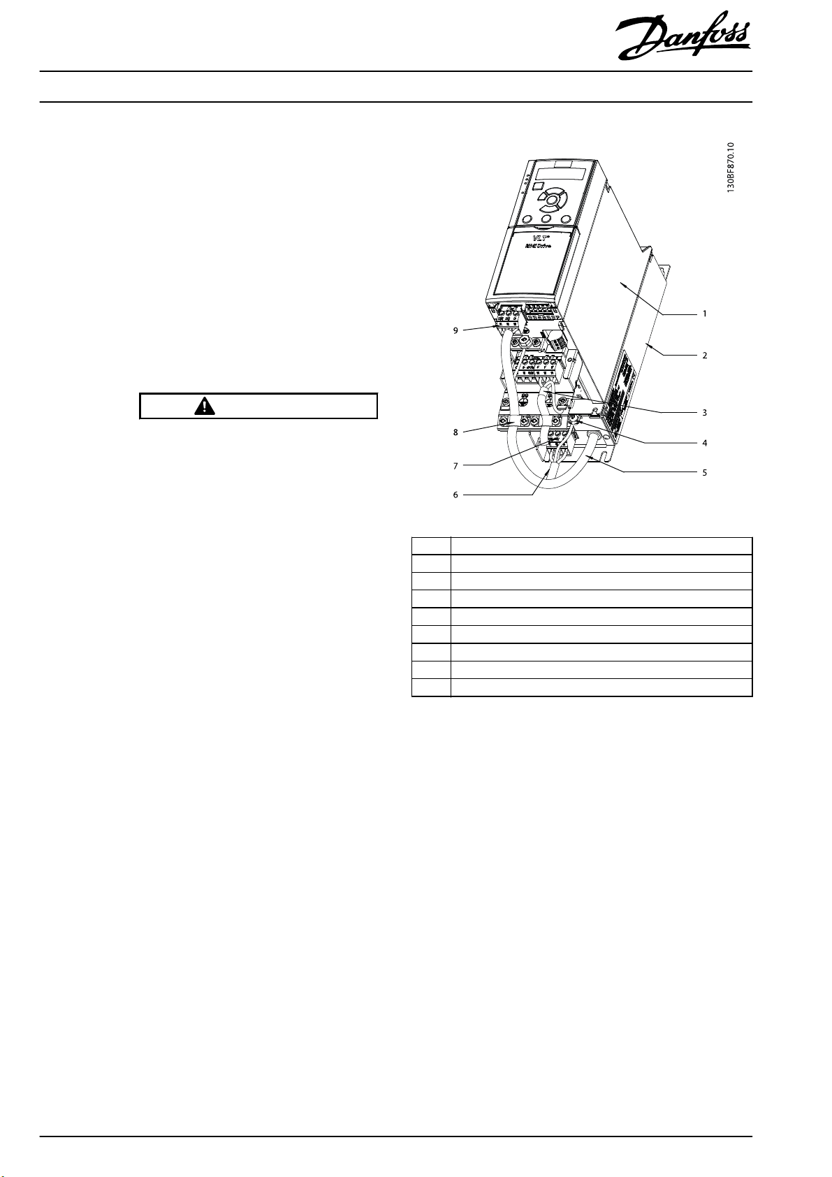
Electrical Installation
1. Connect the cables and fasten the screws as shown
in Illustration 1.5 and Illustration 1.6. Refer to Ta ble 1.5
for the tightening torque of EMC lter terminals.
1a Connect the EMC lter mains output cable
to the frequency converter mains input
terminal block (terminals N (91) and L (92)
for single-phase, or terminals L1 (91), L2
(92), and L3 (93) for 3-phase).
1b Connect the frequency converter mains
input terminal block to the frequency
converter mains input.
1c Secure the cable with the cable clamp.
WARNING
ELECTRICAL HAZARD
Touching the wires of the mains input
while they are not switched o can result
in death or serious injury.
Before continuing, use an
•
appropriate voltage measuring
device to make sure that the
mains input is switched
Ensure that the mains input
•
cannot be switched on by a third
party, while you are working.
1d Connect the wires of the EMC
input cable to the EMC lter mains input
terminal block (terminals N (91) and L (92)
for single-phase, or terminals L1 (91), L2
(92), and L3 (93) for 3-phase).
1e Connect the EMC lter mains input terminal
block to the EMC lter mains input.
1f Connect the ground wire of the EMC
mains input cable to the EMC
terminal.
lter
lter
o.
mains
lter
PE
1 Frequency converter
2EMC lter
3 Cable connecting the frequency converter with the motor
4 EMC lter PE terminal
5 EMC lter mains output cable
6 EMC lter mains input cable
7 EMC lter mains input terminal block
8 Cable clamp
9 Frequency converter mains input terminal block
Illustration 1.5 Cable Connections for Footprint Installation
4
Danfoss A/S © 05/2017, Rev. 02, All rights reserved. MI07L102
Page 5

Installation Instructions
®
VLT
Line Filter MCC 107 EMC Filter Series
®
Midi Drive FC 280 (K1–K3)
VLT
1 Frequency converter mains input terminal block
2 Cable connecting the frequency converter with the motor
3 Cable clamp
4 EMC lter mains output cable
5 EMC lter mains input cable
6 EMC lter mains input terminal block
7EMC lter PE terminal
8EMC lter
9Frequency converter
Illustration 1.6 Cable Connections for Side-by-side Installation
Mains input terminal 0.5–0.8 Nm (4.4–7.1 in-lb)
PE terminal 2.0–2.5 Nm (17.7–22.1 in-lb)
Table 1.5 Tightening Torque for EMC Filter Terminals
EMC lter
ordering number
466 467 463 464 465
134B5xxx
Frequency converter
enclosure size
2
Input [mm
Output [mm
(AWG)]
2
(AWG)]
K1S2 K2S2 K1T4 K2T4 K3T4
3x4 (12)
1.5
(16)
4 (12)
0.75
(18)
1.5 (16) 4 (12)
Cable length for L1‘/L2‘/L3‘(L1’/N’): 280±5
mm (11.0±0.2 in).
Cable length for PE terminal: 220±5 mm
(8.7±0.2 in).
Mains input terminal M3
PE terminal M4
Tab le 1.6
MI07L102 Danfoss A/S © 05/2017, Rev. 02, All rights reserved.
Specications
for EMC Filter Terminals
5
Page 6

Mechanical Data
EMC lter ordering number 134B5466 134B5467 134B5463 134B5464 134B5465
Frequency converter enclosure size K1S2 K2S2 K1T4 K2T4 K3T4
Dimensions A [mm (in)] 250 (9.8) 312.5 (12.3) 250 (9.8) 312.5 (12.3)
Dimensions a1 [mm (in)] 234 (9.2) 303 (11.9) 234 (9.2) 303 (11.9)
Dimensions a2 [mm (in)] 19.5 (0.77) 21.3 (0.84) 19.5 (0.77) 21.3 (0.84)
Dimensions am [mm (in)] 198 (7.8) 260 (10.2) 198 (7.8) 260 (10.2)
Dimensions B [mm (in)] 75 (2.95) 90 (3.54) 75 (2.95) 90 (3.54) 115 (4.53)
Dimensions b1 [mm (in)] 55 (2.17) 70 (2.76) 55 (2.17) 70 (2.76) 90 (3.54)
Dimensions bm [mm (in)] 60 (2.36) 70 (2.76) 60 (2.36) 70 (2.76) 90 (3.54)
Dimensions C [mm (in)] 50 (1.97)
Dimensions c1 [mm (in)] 22.7 (0.89)
Dimensions D1 [mm (in)] Ø5.3 (Ø0.21)
Dimensions Dm [mm (in)] M4 M5 M4 M5
Dimensions e1 [mm (in)] 6.5 (0.26) 5 (0.20) 6.5 (0.26) 5 (0.20)
Dimensions f1 [mm (in)] 10 (0.39) 12.5 (0.49)
Dimensions fm [mm (in)] 7.5 (0.30)
Mounting screws for EMC lter M5
Mounting screws for frequency converter M4 M5 M4 M5
Weight [kg (lb)] 1.10 (2.43)
Illustration 1.7 Mechanical Data
10 (0.39) 7.5 (0.30) 10 (0.39)
1.50 (3.31) 1.20 (2.65) 1.90 (4.19) 2.10 (4.63)
12.5 (0.49)
Danfoss can accept no responsibility for possible errors in catalogues, brochures and other printed material. Danfoss reserves the right to alter its products without notice. This also applies to products already on
order provided that such alterations can be made without subsequential changes being necessary in specifications already agreed. All trademarks in this mate rial are property of the respective companies. Danfoss
and the Danfoss logotype are trademarks of Danfoss A/S. All rights reserved.
Danfoss A/S
Ulsnaes 1
DK-6300 Graasten
vlt-drives.danfoss.com
MI07L102130R0801 05/2017, Rev. 02,
*MI07L102*
 Loading...