

Page 1
Fact Sheet
Operate safely and reduce system cost
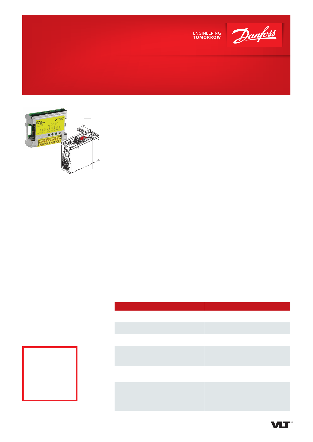
VLT® Safety Option MCB 150/151 and VLT® Sensorless Safety MCB 159
MC B 151
MC B 159
Ordering number
MCB 150 ................................ 130B3280 coated
MCB 151 ................................ 13 0 B329 0 coated
MCB 159 – select this option in the
configurator when ordering a new drive.
Not available for retrofit.
Reduce overall system cost,
improve flexibility and
increase productivity by
enabling operators to perform
maintenance safely, even
while the machine is still in
motion.
Additional safety
The VLT® Safety Option MCB 150/151
expands the integrated Safe Torque Off
(STO) function of the VLT® AutomationDrive. Use the Safe Stop 1 (SS1)
function to perform a controlled stop,
before removing torque. Use the Safely
Limited Speed (SLS) and Safe Maximum
Speed (SMS) functions to monitor
whether a specified speed is exceeded.
When the VLT® Safety Option MCB 151
is combined with the built-in
VLT® Sensorless Safety MCB 159 option,
an external sensor is no longer required
for safe speed monitoring.
Use flexible speed control in
upgraded or retrofitted applications.
Connect input devices – such as guard
locking switches, light curtains and
emergency stops – directly to the
module and eliminate the need for a
separate, dedicated safety controller.
Quick commissioning
and wiring
Visual instructions in VLT® Motion
Control Tool MCT 10 ensure both
fault- free wiring and that safety
parameters are correctly transferred
from the PC to the drive. The software
also offers a dynamic commissioning
report which can be used in the
technical file for the machine.
More advantages
Integrated functional safety replaces
external safety equipment
Reduced space requirements
Can send status messages via
Fieldbus
Password function
Logging function
Simpler feedback sensor systems
Compliance with international
standards
Easier machine certification
Drive can be powered continuously
100%
integrated into the
drive due to internal
databus connection
Feature Benefit
No need to power cycle the drive after
a demand on the safety system
Two logic safety inputs
Maintenance can be performed while the machine
is still in motion
Safe Torque Off (STO)
Integrated in the drive as standard
Safe Stop 1 (SS1)
Monitors deceleration and then
shuts off the torque
Safely Limited Speed (SLS)/
Safe Maximum Speed (SMS)
Monitors whether a specified velocity
is exceeded
– Minimized wear on the drive
– Provide redundancy without needing an
external safety module
– Minimized time and effort required for
service and installation work
– Increased productivity and availability
– Eliminates one or more power contactors
– Eliminates the need for additional feedback
monitoring
– Machine is restarted quickly and more simply
– Greater operational safety, as the machine is
protected against unexpected restart
– Safe protection against overspeed
– Makes it possible to work safely with
the guards open
– Reduced set-up times thanks to a better view
into the set-up area
– Safe Jog function
drives.danfoss.com
Page 2
Approvals
The VLT® Safety Options are approved
for use in safety related control systems
and comply with EN ISO 13849-1 PL d,
EN IEC 61508 SIL 2 and EN IEC 62061.
The safety options offer the
following safety functions in
compliance with IEC 61800-5-2:
Safe Torque Off (STO)
Activation
of STO
Frequency
Actual frequency
Time
of SS1
Safe Stop 1(SS1)
Activation
of STO
Ramp time
Actual frequency
SS1 ramp
Time
Activation
Frequency
Specifications
Digital inputs
Number of programmable digital inputs 4 (2 x 2-channel Digital Safety Input)
Input voltage range 0-24 VDC
Input voltage Low: < 5 VDC / High: > 12 VDC
Input current (min) 6 mA @Vin=24V (for keeping contacts clean)
Galvanic isolation No
Reaction time < 5ms (in total for HW and SW response time)
Short circuit-proof Yes
TTL Encoder input (MCB 150)
Number of encoder inputs (4 x differential inputs A,/A ; B,/B)
Encoder types TTL, RS422/RS485 incremental encoders
Input voltage range -7 to 12 VDC
Maximum frequency 410 KHz
Short circuit-proof Yes
Cable length < 100 m (shielded cable)
HTL Encoder input (MCB 151)
Number of encoder inputs 2 (2 x single ended inputs A; B)
Encoder types
Input voltage range 0 to 24 VDC
Input voltage Low: < 5 VDC / High: > 12 VDC
Maximum frequency 110 KHz
Short circuit-proof Yes
Cable length < 100 m (shielded cable)
24 V supply output
Supply voltage 24 VDC (Voltage tolerance: +10%, -15%)
Maximum output current 150 mA
Short circuit-proof Yes
Certifications
Safety integrity level (SIL1, 2) according to EN IEC 62061, EN IEC 61508 standard (par ts 1, 2 and 3)
Performance level (PL “d”) according to EN ISO 13849-1 Category 3
HTL incremental encoders; HTL Proximity sensor,
no encoder (when equipped with MCB 159)
Safely Limited Speed (SLS)
SLS activated
Frequency
Max
speed
limit
Safe Maximum Speed (SMS)
Frequency
Actual frequency
SLS max speed limit
Actual frequency
SMS max speed limit
Time
Time
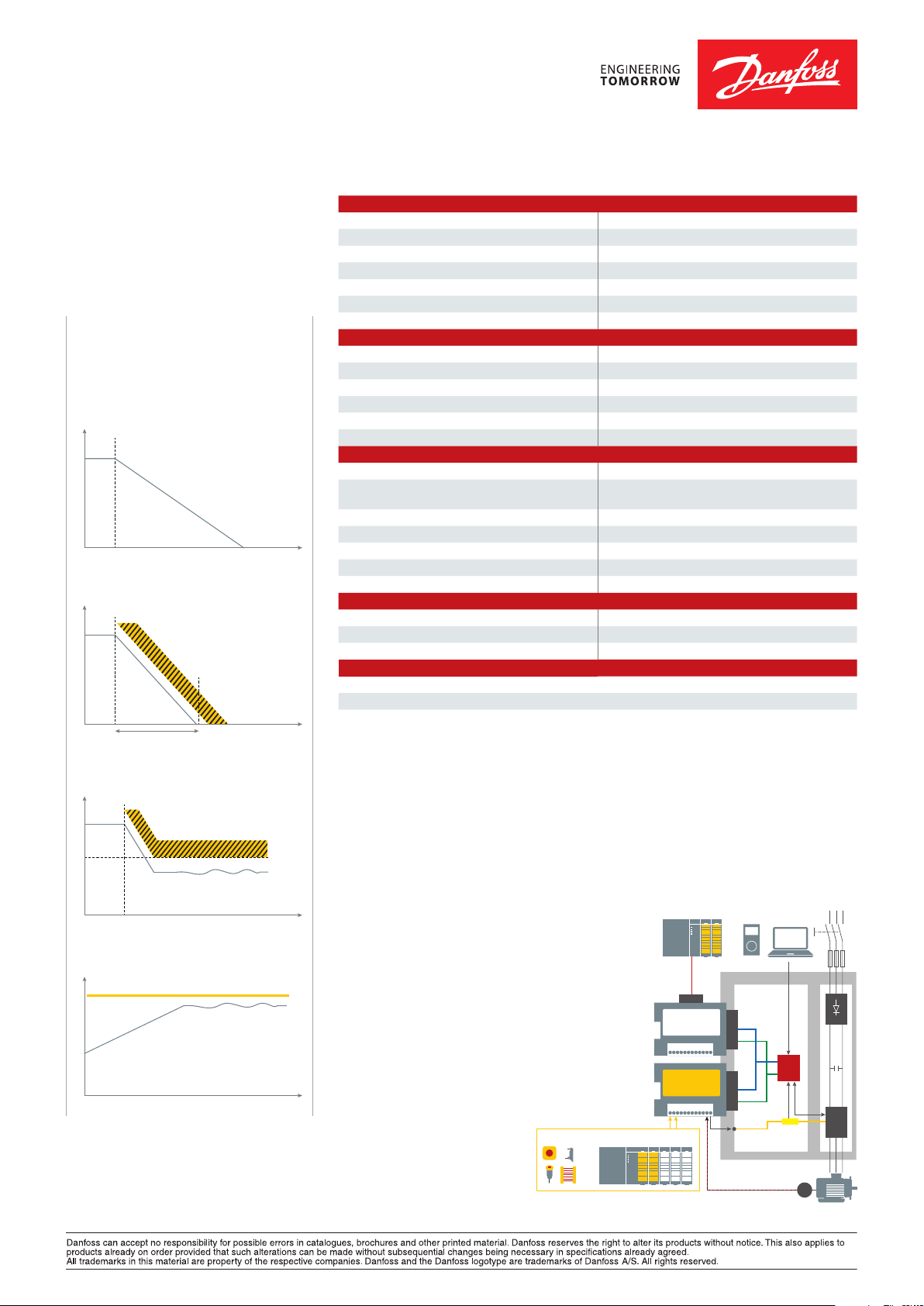
The VLT® Safety Option MCB 150/151
provides an intelligent, programmable
solution to meet EN IEC 61800-5-2
functional safety standards. It fits within
the drive and helps to reduce cabling,
requiring no cabinet space or external
power supply.
Connect active and passive sensors
directly to the pluggable safety
option over two channels. In many
applications you can then eliminate
external components, such as safety
switchgear, over-speed monitors, speed
encoders, and motor/mains contactors.
STOP
RT
There are different hardware variants
for HTL (MCB 151), sensorless operation (MCB 151 with MCB 159), and TTL
(MCB 150) encoder input. Each makes
use of the existing Safe Stop, terminal
37, via an external wire.
Control Card
37
Internal bus 1
Option AOption B
Internal bus 2
STO
µC
Safe
channel
E
Fieldbus Interface
VLT® Safety Option
MCB 150/151
Active sensorsPassive sensors
IGBT
DKDD.PFO.607.A4.02 © Copyright Danfoss Drives | 2018.09
EtherNet/IP™ and DeviceNet™ are trademarks of ODVA, Inc.
 Loading...