

MAKING MODERN LIVING POSSIBLE
Operating Instructions
VLT® PTC Thermistor Card MCB 112
VLT® HVAC Drive FC 102 • VLT® AQUA Drive FC 202
VLT® AutomationDrive FC 302
vlt-drives.danfoss.com


Contents Operating Instructions
Contents
1 Introduction
1.1 Purpose of the Manual
1.2 Additional Resources
1.3 Document and Software Version
1.4 Products Covered
1.5 Functional Overview
1.5.1 Intended Use 3
1.5.2 Foreseeable Misuse 4
1.5.3 Thermal Motor Protection 4
1.5.4 ATEX ETR Thermal Monitoring 4
1.5.5 Tripping Function 4
1.5.6 Safe Separation 4
1.5.7 Safe Disconnection Principle 4
1.6 Motor Requirements
1.6.1 Motor Limits and Rules 5
1.6.2 Additional Motor Requirements 5
1.7 Approvals and Certications
3
3
3
3
3
3
5
5
1.8 Symbols, Abbreviations, and Conventions
2 Safety
2.1 Safety Symbols
2.2 Qualied Personnel
2.3 Safety Precautions
3 Installation
3.1 Safety Instructions
3.2 Installation of Sensor Circuit Wires
3.3 Installation of the VLT® PTC Thermistor Card MCB 112
4 Commissioning
4.1 Operation and Maintenance
4.1.1 Monitoring Sensor Resistance 12
4.2 Parameter Set-up
4.2.1 Alarm Handling 13
4.3 Parameter Set-up for Ex-e and Ex-n Motors
6
7
7
7
7
9
9
9
10
12
12
13
14
4.3.1 Maximum Current 14
4.3.2 Maximum Current Limit 14
4.3.3 Minimum Motor Frequency 14
4.3.4 Maximum Motor Frequency 15
4.3.5 Minimum Switching Frequency 15
MG33V302 Danfoss A/S © 01/2015 All rights reserved. 1
Contents
VLT® PTC Thermistor Card MCB 112
4.3.6 Disable Protection Mode 15
4.3.7 Safe Torque O Functionality 15
5 Application Examples
6 Maintenance and Troubleshooting
6.1 Maintenance
6.2 Troubleshooting
6.2.1 Alarm/Warning Code List 19
6.2.2 Description of Alarm Word, Warning Word, and Extended Status Word 19
7 Technical Specications
7.1 Mains Supply
7.2 Control Inputs and Outputs
7.3 Ambient Conditions
7.4 Other Specications
7.5 Safety Characteristics of the Built-in MCB 112
Index
17
19
19
19
21
21
21
21
22
22
23
2 Danfoss A/S © 01/2015 All rights reserved. MG33V302

Introduction Operating Instructions
1 Introduction
1
1
1.1 Purpose of the Manual
This manual provides information for safe installation and
commissioning of VLT® PTC Thermistor Card MCB 112 used
with a Danfoss VLT® frequency converter with Safe Torque
O (STO). The manual is intended for use by qualied
personnel only.
VLT® PTC Thermistor Card MCB 112 is also referred to as
MS 220 DA.
The operating instructions are intended for use by
qualied personnel. Read and follow the operating
instructions to use the frequency converter safely and
professionally, and pay particular attention to the safety
instructions and general warnings. Keep these operating
instructions available with the frequency converter at all
times.
VLT® is a registered trademark.
1.2 Additional Resources
This manual is targeted at users already familiar with the
VLT® frequency converters. It is intended as a supplement
to the manuals and instructions available for download at
vlt-drives.danfoss.com/Support/Technical-Documentation/.
Read the instructions shipped with the frequency
converter and/or frequency converter option before
installing the unit, and observe the instructions for safe
installation.
1.3
Document and Software Version
1.4
Products Covered
The VLT® PTC Thermistor Card MCB 112 is available for the
following types of frequency converters:
VLT® HVAC Drive FC 102.
•
VLT® AQUA Drive FC 202.
•
VLT® AutomationDrive FC 302.
•
1.5 Functional Overview
1.5.1 Intended Use
The VLT® PTC Thermistor Card MCB 112 is intended to:
Protect electrical motors against inadmissible
•
heating due to overload.
Protect explosion-protected motors in explosive
•
atmospheres caused by gases, vapours, or mists,
Zone 1 and Zone 2, and/or in explosive
atmospheres caused by dust, Zone 21 and Zone
22. Refer to marking G for Zone 1 and Zone 2.
Refer to marking D for Zone 21 and Zone 22.
All functions in the MCB 112 serve to protect both nonexplosive-protected motors and explosive-protected
motors in regular operation and in case of failure.
The VLT® PTC Thermistor Card MCB 112 is designed in
accordance with EN 60947-8 (VDE 0660 part 0302). Only
connect PTC thermistor sensors according to DIN 44081
and 44082 (EN 60947-8).
This manual is regularly reviewed and updated. All
suggestions for improvement are welcome. Please send
suggestions via email to
techcom_change_request@danfoss.com, including a
reference to the document version. Table 1.1 shows the
document version and the changes applied.
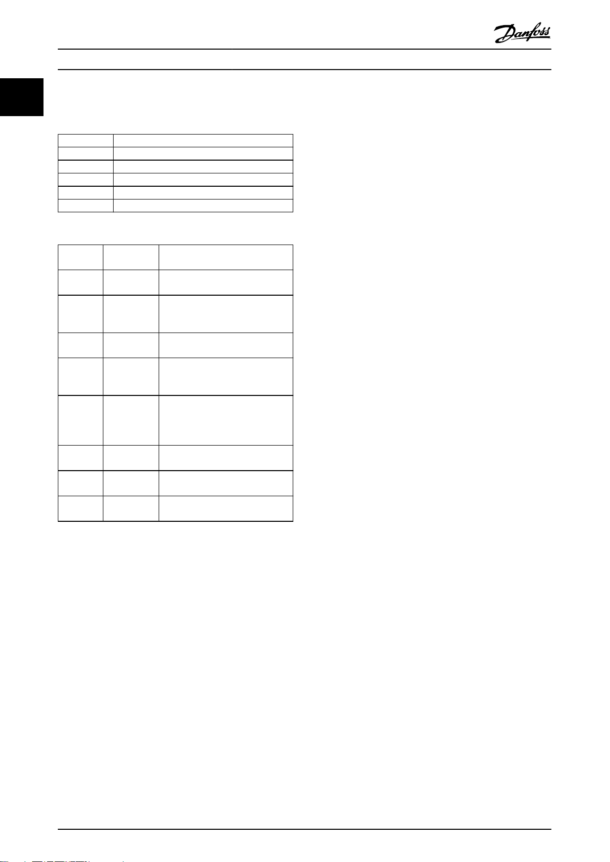
Edition Remarks
MG33V3xx Replaces MG33V2xx.
Editorial changes.
Now covering the complete system.
Table 1.1 Document Version
MG33V302 Danfoss A/S © 01/2015 All rights reserved. 3
NOTICE
The VLT® PTC Thermistor Card MCB 112 is only functional
if it is built into the frequency converter. The option
cannot be used as a stand-alone.
MS 220 DA / MCB112
Code no.: 130B1137
Motor protection inside
See manual
for additional instruction
PTB 14 ATEX 3012U
CAUTION:
II (2) D [Ex tb][Ex tc]
II (2) G [Ex e] [Ex d] [Ex n]
ε
130BE103.10
Introduction
VLT® PTC Thermistor Card MCB 112
1
1.5.1.1 Markings of the Frequency
Converter
A sticker is delivered with the option as spare part or with
the frequency converter to signify ATEX certication. Apply
this sticker to the front of the frequency converter in
which the ATEX module is integrated. The sticker indicates
that the ATEX module is installed in the frequency
converter.
Illustration 1.1 Label to Apply to Frequency Converter
Foreseeable Misuse
1.5.2
Any use not expressly approved by Danfoss constitutes
misuse. This also applies to failure to comply with the
specied operating conditions and applications.
according to DIN 44081 or 44082, the MCB 112 oers
ATEX-approved monitoring of the motor temperature.
Alternatively, an external ATEX-approved PTC protection
device can be used.
1.5.4 ATEX ETR Thermal Monitoring
NOTICE
The ATEX ETR thermal monitoring function only applies
to Ex-e and Ex-n motors and is only available for VLT
AutomationDrive FC 302 frequency converters.
The FC 302 with
equipped with an ATEX ETR thermal monitoring function
for operation of Ex-e motors according to EN 60079-7 and
Ex-n motors according to EN 60079-15. Combined with an
ATEX-approved PTC monitoring device like MCB 112, the
installation does not need an individual approval from an
approbated organisation, that there is no need for
matched pairs.
The feature makes it easier to apply Ex-e and Ex-n motors
instead of the more expensive, larger, and heavier Ex-d
motors. The use of Ex-e and Ex-n motors is possible by
ensuring that the frequency converter limits the motor
current to prevent the motor from heating up.
Tripping Function
1.5.5
rmware version V6.3x or higher is
®
Danfoss assumes no liability of any sort for damage attributable to improper use.
Only operate with explosion-protected 3-phase motors
which are built, tested and labelled separately for
frequency converter use.
WARNING
EXPLOSION DANGER
Zone 0 and Zone 20 are not applicable to electric
motors.
To avoid explosion, only use motors in:
Zone 1/21.
•
Zone 2/22.
•
1.5.3 Thermal Motor Protection
According to ATEX Directive 94/9/EC and Standard EN
60079-14, motor overload protection is a requirement.
The MCB 112 monitors the temperature in the motor
windings with an ATEX-approved motor overload
protection device. If there is a critical temperature level or
a malfunction, switch o the motor. If the frequency
converter is equipped with 3–6 PTC thermistors in series
The MCB 112 includes a tripping stage for PTC thermistor
sensors with safe potential separation of supply voltage
from ground. The tripping function switches o the +24 V
DC directly at terminal 37 on the frequency converter.
The PNP logic output terminal X44/10 signals the status in
case of failure. The MCB 112 works according to the
closed-circuit principle. The device trips in case of short
circuit or line interruption.
Safe Separation
1.5.6
The PTC thermistor circuit (T1, T2) has a safe separation of
low-voltage electric circuits PELV, see chapter 3.2 Instal-
lation of Sensor Circuit Wires.
1.5.7
Safe Disconnection Principle
The Safe Torque O function disables the control voltage
of the power semiconductors or the frequency converter
output stage. Disabling the control voltage prevents the
inverter from generating the voltage required to rotate the
motor.
4 Danfoss A/S © 01/2015 All rights reserved. MG33V302
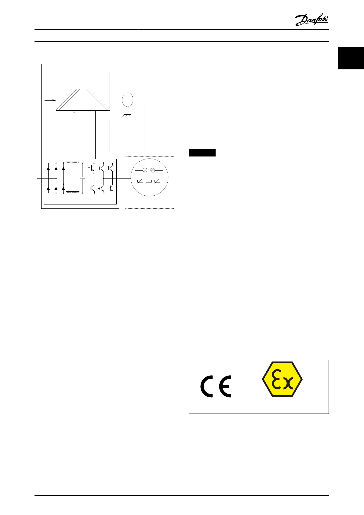
Frequency Converter
Logic
Out
Control Card
Potentially explosive
atmosphere
PTC-Sensors
3~ Ex-Motor
Safe Channel T37
Safe Stop
T37
T1
TP TP
T2
+24 V
PTC Thermistor Card
MCB 112
Non-explosive hazard zone
91
92
93
96
97
98
Converter module
130BE102.10
DI
Introduction
Illustration 1.2 Block Diagram of the System
Operating Instructions
1.6 Motor Requirements
1.6.1 Motor Limits and Rules
For every certied motor with increased safety, the
manufacturer supplies a data list including limits and rules.
During planning, installation, commissioning, operation,
and service, respect the limits for:
Minimum switching frequency.
•
Maximum current.
•
Minimum motor frequency.
•
Maximum motor frequency.
•
Furthermore, respect the following:
1.6.2
Additional Motor Requirements
The Ex-e motor must be approved for operation in
hazardous zones (ATEX Zone 1/21, ATEX Zone 2/22) in
combination with frequency converters. The motor must
be certied for the particular hazardous zone.
The Ex-n motor must be approved for operation in
hazardous zones (ATEX Zone 2/22) in combination with
frequency conveters. The motor must be certied for the
particular harzardous zone.
NOTICE
The motor can be placed in Zone 1/21 or 2/22 according
to motor approval. The frequency converter must always
be installed outside of the hazardous zone.
Only operate explosion-protected 3-phase motors
•
with frequency converters, if the motors are built,
tested, approved, and labelled separately for this
mode.
When the usage of the motor and its thermal
•
protective device are approved for frequency
converter operation, use the MCB 112 for each
ignition protection system for all motor types. For
motors of Ex-e and Ex-n-type ignition protection,
which are OEM-approved for frequency converter
operation in Ex-harzardous areas, consider and
use the requested limitations in the frequency
converter’s ATEX ETR thermal monitoring settings.
The necessary parameters and conditions can be
•
found on the nameplate or the documentation of
the motor. To prevent prohibited temperatures,
the motors are equipped as standard with
thermal winding protection, which has to be
evaluated by a suitable device like MCB 112. The
motors must not be operated as a group drive.
1.7
Approvals and Certications
1
1
MG33V302 Danfoss A/S © 01/2015 All rights reserved. 5
Do not exceed the maximum allowable ratio
•
between frequency converter size and motor size.
The typical value is I
Consider all voltage drops from the frequency
•
converter to the motor. If the motor is running
with lower voltage than listed in the U/f characteristics, current might increase and cause an
alarm.
Multi-motor applications are not allowed. Only
•
connect 1 motor to the frequency converter.
≤2xI
VLT, n
m,n
.
Certication number:
PTB 14 ATEX 3012U
Certicates and declarations of conformity are available.
Contact a local Danfoss partner.
Introduction
VLT® PTC Thermistor Card MCB 112
1
1.8 Symbols, Abbreviations, and
Conventions
Abbreviation Description
ETR Electronic thermal relay.
LCP Local control panel.
NC Not connected.
PNP Positive negative positive (transistor).
TNF Nominal response temperature.
Table 1.2 Abbreviations
AbbreviationReference Description
ATEX ATEX Directive
94/9/EC
HFT EN IEC 61508 Hardware fault tolerance: HFT=n
PDS/SR EN IEC
61800-5-2
PFD EN IEC 61508 Average probability of failure on
SFF EN IEC 61508 Safe failure fraction [%]; percentage
SIL EN IEC 61508
EN IEC 62061
STO EN IEC
61800-5-2
SRECS EN IEC 62061 Safety-related electrical control
ATmosphere EXplosibles
means that n+1 faults could cause a
loss of the safety function.
Power drive system (safety-related).
demand, value used for lowdemand operation.
of safe failures and dangerous
detected failures of a safety function
or a subsystem related to all failures.
Safety integrity level.
Safe Torque O.
system.
Table 1.3 Abbreviations Related to Functional Safety
Conventions
Numbered lists indicate procedures.
Bullet lists indicate other information and description of
illustrations.
Italicised text indicates:
Cross-reference.
•
Link.
•
Parameter name.
•
6 Danfoss A/S © 01/2015 All rights reserved. MG33V302
Safety Operating Instructions
2 Safety
2.1 Safety Symbols
The following symbols are used in this manual:
WARNING
Indicates a potentially hazardous situation that could
result in death or serious injury.
CAUTION
Indicates a potentially hazardous situation that could
result in minor or moderate injury. It can also be used to
alert against unsafe practices.
NOTICE
Indicates important information, including situations that
can result in damage to equipment or property.
2.2 Qualied Personnel
The products must only be assembled, installed,
programmed, commissioned, maintained, and decommissioned by persons with proven skills. Persons with proven
skills:
Are qualied electrical engineers, or persons who
•
have received training from qualied electrical
engineers and are suitably experienced to
operate devices, systems, plant, and machinery in
accordance with the general standards and
guidelines for safety technology.
Are familiar with the basic regulations concerning
•
health and safety/accident prevention.
Have read and understood the safety guidelines
•
given in this manual and also the instructions
given in the operating instructions of the
frequency converter.
Have a good knowledge of the generic and
•
specialist standards applicable to the specic
application.
Users of PDS(SR) are responsible for:
Hazard and risk analysis of the application. In EN
•
ISO 12100, risk assessment is dened as an
overall process comprising a risk analysis and a
risk evaluation.
Ensuring that the qualied personnel has
•
experience with working in ATEX areas according
to Directive 99/92/EC (also known as the ATEX
Workplace Directive).
Identifying safety functions required, and
•
allocating SIL to each of the functions.
Other subsystems and the validity of signals and
•
commands from those subsystems.
Designing appropriate safety-related control
•
systems (hardware, software, parameterisation,
and so on).
Protective measures
Safety engineering systems must only be installed
•
and commissioned by qualied and skilled
personnel.
Install the frequency converter in an IP54 cabinet
•
as per IEC 60529, or in an equivalent
environment. In special applications, a higher IP
degree may be necessary.
Ensure short-circuit protection of the cable
•
between terminal 37 and the external safety
device according to ISO 13849-2 table D.4.
When external forces inuence the motor axis (for
•
example suspended loads), additional measures
(for example a safety holding brake) are required
to eliminate hazards.
2.3
Safety Precautions
WARNING
EXPLOSION HAZARD
Using the VLT® PTC Thermistor Card MCB 112 in areas
with explosive gas and/or dust atmosphere may lead to
death, personal injury, or property damage. To avoid the
risk, adhere to the following:
Always provide the MCB 112 with a pressurised
•
enclosure according to EN 60079-1 (Explosive
atmospheres - Part 1: Equipment protection by
ameproof enclosures “d”).
Observe national safety rules and regulations
•
for prevention of accidents, as well as the
European Standard EN 60079-14 (Explosive
atmospheres - Part 14: Electrical installations
design, selection, and erection).
Only
•
•
qualied personnel (see
chapter 2.2 Qualied Personnel) is allowed to
install, connect, and commission the MCB 112.
Ensure that the motor thermal protection
switches o the motor directly, via the STO
function, or by using the ATEX ETR thermal
monitoring function.
2 2
MG33V302 Danfoss A/S © 01/2015 All rights reserved. 7
Safety
VLT® PTC Thermistor Card MCB 112
WARNING
FIRE HAZARD
22
Using the VLT® PTC Thermistor Card MCB 112 in areas
with combustible dust may lead to death, personal
injury, or property damage. To avoid the risk, adhere to
the following:
Always provide the MCB 112 with a dust-proof
•
enclosure according to IEC 60529.
Observe national safety rules and regulations
•
for prevention of accidents, as well as the
European Standard EN 60079-14 (Explosive
atmospheres - Part 14: Electrical installations,
design, selection, and erection).
Only qualied personnel (see
•
chapter 2.2 Qualied Personnel) is allowed to
install, connect, and commission the MCB 112.
WARNING
UNINTENDED START
When the frequency converter is connected to AC mains,
the motor may start at any time, causing risk of death,
serious injury, equipment, or property damage. The
motor can start by means of an external switch, a serial
bus command, an input reference signal from the LCP,
after a cleared fault condition, or after the motor and
motor thermistors have cooled down.
Disconnect the frequency converter from mains
•
whenever personal safety considerations make
it necessary to avoid unintended motor start.
Press [O] on the LCP, before programming
•
parameters.
The frequency converter, motor, and any driven
•
equipment must be in operational readiness
when the frequency converter is connected to
AC mains.
CAUTION
RISK OF INJURY AND EQUIPMENT DAMAGE
Read and observe these operating instructions and
safety warnings before installing the VLT® PTC
Thermistor Card MCB 112. Not adhering to the
instructions and warnings in this manual may lead to
personal injury, and property and equipment damage.
8 Danfoss A/S © 01/2015 All rights reserved. MG33V302

130BT340.11
1
2
Installation Operating Instructions
3 Installation
3.1 Safety Instructions
CAUTION
The operator or electrical installer is responsible for
proper grounding and compliance with all applicable
national and local safety regulations.
See chapter 2 Safety and the relevant frequency converter
operating instructions. Also, always observe the
instructions provided by the motor manufacturer.
3 3
3.2 Installation of Sensor Circuit Wires
NOTICE
The connections are not pre-wired from the factory.
WARNING
NO SAFE FUNCTION
Using sensor wires with a resistance >20 Ω causes the
safe function not to work.
To ensure a properly working safe function, only use
sensor circuit wires with a resistance <20 Ω.
Sensor circuit wire connection
2
Wire cross-section [mm
1.5 2 x 800
1 2 x 500
0.75 2 x 300
0.5 2 x 250
Table 3.1 Maximum Permissible Length of Sensor Circuit Wires
]
Wire length [m]
NOTICE
Route the sensor circuit wires as separate control wires.
It is not allowed to use wires from the supply cable or
any other mains cables. Use screened control wires. See
Illustration 3.2 for correct wiring.
1. Select appropriate sensor wires.
2. Route the sensor wires.
3. Remove the screening in the area of the
screening clamps and press the wires into the
clamps.
1
Screening clamps
2 Removed screening
Illustration 3.1 Connecting Screened Wire
4. Measure the sensor resistance.
5. Connect the sensor circuit wires to X44/T1 and
T2. See Illustration 3.2.
NOTICE
Only check PTCs with measuring voltages of <2.5 V.
At commissioning and after modication of the plant,
check the sensor resistance with a suitable measuring
instrument. If the resistance between terminals 1 and 2 is
<50 Ω, examine the sensor circuit for a short circuit.
MG33V302 Danfoss A/S © 01/2015 All rights reserved. 9

PTC
M 3~
TP TP
12 13 18 19 27 29 32 33 20 37
MS 220 DA
Code No. 130B1137
Motor protection
SEE MANUAL FOR
MCB 112 PTC Thermistor Option B
ADDITIONAL INSTRUCTIONS.
PTB 14 ATEX 3012U
CAUTION:
II (2) G [Ex e] [Ex d] [Ex n]
ε
10 10 mA
60 mA
12
20-28 VDC
20-28 VDC
II (2) D [Ex tb][Ex tc]
0102
12030-1201-03
.com
X44
1
T1 T2 NC NC NC
NC NC NC NC NC
LOGIC SAFE STOP
OUT T37
2 3 4 5 6 7 8 9 10 11 12
130BB161.11
130BE118.10
A
B
D
12/13
37
130BE099.10
Installation
VLT® PTC Thermistor Card MCB 112
Maximum current on MCB 112
Terminal 10: 10 mA.
•
Terminal 12: 60 mA.
•
CAUTION
Place the frequency converter with MCB 112 (including
the connection between output safe stop T37 output
(X44/12) on MCB 112 and terminal 37 input on the
control card) in an IP54 enclosure as per IEC 60529.
33
Installing the MCB 112
Illustration 3.2 Wiring Diagram
3.3
Installation of the VLT® PTC Thermistor
Card MCB 112
For motor connection, AC mains connection, and control
wiring, follow the instructions for safe installation in the
operating instructions of the frequency converter and the
VLT® Frequency Converter - Safe Torque O Operating
Instructions.
Terminal Description.
Terminal 12 24 V DC supply voltage.
Terminal 13 24 V DC supply voltage.
T37 (X44/12) Output terminal on the MCB 112 option.
Terminal 37 Input terminal on the control card.
X44/10 Logic output signals the status in case of
Table 3.2 Terminal Denitions
RISK OF OVERVOLTAGE
Long cables (voltage peaks) or increased mains voltage
CAUTION
may lead to overvoltage at the motor terminals and
damage the equipment.
Install a sine-wave lter.
•
failure.
Illustration 3.3 LCP Frame and Terminal Cover Removal
1. Disconnect power to the frequency converter.
2. Remove the LCP, the terminal cover, and the LCP
frame from the frequency converter.
3.
Fit the MCB 112 in slot B, see Illustration 3.3.
Wiring
1. Remove the jumper wire between control
terminals 37 and 12 or 13.
Cutting or breaking the jumper is not
•
sucient to avoid short circuiting.
2. Connect X44/12 on the option card to terminal
37 on the frequency converter.
10 Danfoss A/S © 01/2015 All rights reserved. MG33V302

Installation Operating Instructions
3. Connect terminal X44/10 to a digital input of the
frequency converter. For reference when
programming, note the number of selected
digital input.
Assembly
1. Remove the knock-out in the extended LCP
frame, so that the option ts under the extended
LCP frame.
2. Fit the extended LCP frame and terminal cover.
3. Fit the LCP or blind cover in the extended LCP
frame.
4. To indicate that the ATEX module is integrated,
apply the delivered sticker to the front of the
frequency converter, see Illustration 1.1.
5. Connect power to the frequency converter.
6. Perform risk assessment and a commissioning
test according to EN ISO 12100.
3 3
MG33V302 Danfoss A/S © 01/2015 All rights reserved. 11

Commissioning
4 Commissioning
VLT® PTC Thermistor Card MCB 112
Refer to the chapter Commissioning in the VLT® Frequency
Converters Safe Torque O Operating Instructions.
4.1 Operation and Maintenance
The safety function must be tested within regular intervals.
44
Test once per year, or within the maintenance cycle of the
plant. For recurring examinations of electrical systems in
hazardous areas, the inspection period must be kept within
3 years.
The safety test recognises 1 fault (1oo1 - 1 out of 1). One
fault between safety tests can cause loss of protection.
Commissioning test
Test the correct function of the MCB 112 by simulation of
the sensor resistance at terminals T1 and T2. This test must
also be done at maintenance services.
The tripping function is stated in the LCP and can be reset
manually when the failure is removed. Pay attention to the
ambient conditions in chapter 7 Technical Specications.
Short-circuit test: Resistance 20 Ω in parallel to
•
sensor terminals T1, T2.
Line interruption test: Disconnect sensor line at
•
terminal T1 or T2.
Temperature test: Increase resistance 50–1500 Ω
•
to 4000 Ω.
4.1.1 Monitoring Sensor Resistance
1) Short circuit
2) Tripping is not saved, and is not protected against 0 voltage
Illustration 4.1 Monitoring of Sensor Resistance
A current continuously monitors the resistance of the
sensors. In cold state, the resistance is <250 Ω per sensor
(sensor circuit <1.5 kΩ). The output to terminal X44/12 is
high=1. The resistance of the sensor rises rapidly at
nominal response temperature TNF. At a resistance of 3–4
kΩ, output to terminal X44/12 changes to low=0. The
devices also switch o if the sensor or wire short-circuits
(<20 Ω), or if the sensor or wire is interrupted. It switches
back on automatically when the temperature has
decreased by approximately 5 °C.
12 Danfoss A/S © 01/2015 All rights reserved. MG33V302
Depending on the number of sensors, the following
tripping and release temperatures are achieved with
respect to TNF (nominal response temperature of the
sensors):
Trip temperature Release temperature
3 sensors in series TNF+5 K TNF-5 K
6 sensors in series TNF TNF-20 K
Table 4.1 Tripping and Release Temperatures

1 0 0 %
8 0 %
4 0 %
5 Hz 15 Hz 25 Hz 50 Hz
130BB909.10
130BD888.10
CONVERTER SUPPLY
VALID FOR 380 - 415V FWP 50Hz
3 ~ Motor
MIN. SWITCHING FREQ. FOR PWM CONV. 3kHz
l = 1.5XI
M,N
tOL = 10s tCOOL = 10min
MIN. FREQ. 5Hz MAX. FREQ. 85 Hz
PWM-CONTROL
f [Hz]
Ix/I
M,N
PTC °C DIN 44081/-82
Manufacture xx
EN 60079-0
EN 60079-7
СЄ 1180 Ex-e ll T3
5 15 25 50 85
0.4 0.8 1.0 1.0 0.95
1
2
3
4
xЗ
Commissioning
Operating Instructions
4.1.2 Thermal Limitation Curve
WARNING
EXPLOSION DANGER
Always use the thermal limitation curve in combination
with Ex-e and Ex-n motors. See Illustration 4.2.
The output current/motor speed is permanently monitored
and limited depending on the characteristic given by the
motor manufacturer on the motor nameplate and data
sheets.
1. Programme the characteristic values as
frequency/current pairs in parameters 1-98 ATEX
ETR interpol. points freq. and 1-99 ATEX ETR interpol
points current.
Minimum switching frequency
1
2 Maximum current
3 Minimum motor frequency
4 Maximum motor frequency
4 4
Illustration 4.2 Example of ATEX ETR Thermal Limitation Curve
1-98 ATEX ETR interpol. points freq. 1-99 ATEX ETR interpol
[0]=5 Hz [0]=40%
[1]=15 Hz [1]=80%
[2]=25 Hz [2]=100%
[3]=50 Hz [3]=100%
Table 4.2 Ratio between Motor Speed and Motor Current
MG33V302 Danfoss A/S © 01/2015 All rights reserved. 13
points current
Illustration 4.3 Motor Nameplate Showing Frequency
Converter Requirements
2. Use the 4 current points [A] from the motor
nameplate.
3. Calculate the values as a percentage of nominal
motor current and enter it into the array.
Ix × 100
%
Im, n
4. Programme all frequency/current limit points
from the motor nameplate or motor data sheet.
5.
Enter frequency settings for 1-98 ATEX ETR
interpol. points freq. in Hz, not RPM.
4.2
Parameter Set-up
4.2.1 Alarm Handling
The digital input is congured in parameter group 5-1*
Digital Inputs.
Digital input function Select Terminal
No operation [0] All *terminals 32, 33
Reset [1] All
...
PTC Card 1 [80] All
...
Table 4.3 5-1* Digital Inputs

Commissioning
VLT® PTC Thermistor Card MCB 112
All digital inputs can be set to [80] PTC Card 1. However,
only 1 digital input can have this selection.
NOTICE
Ensure that the digital input set to [80] PTC Card 1 is not
also connected as a thermistor resource (motor overload
protection) in 1-93 Thermistor Resource.
44
For further description, refer to the relevant frequency
converter programming guide.
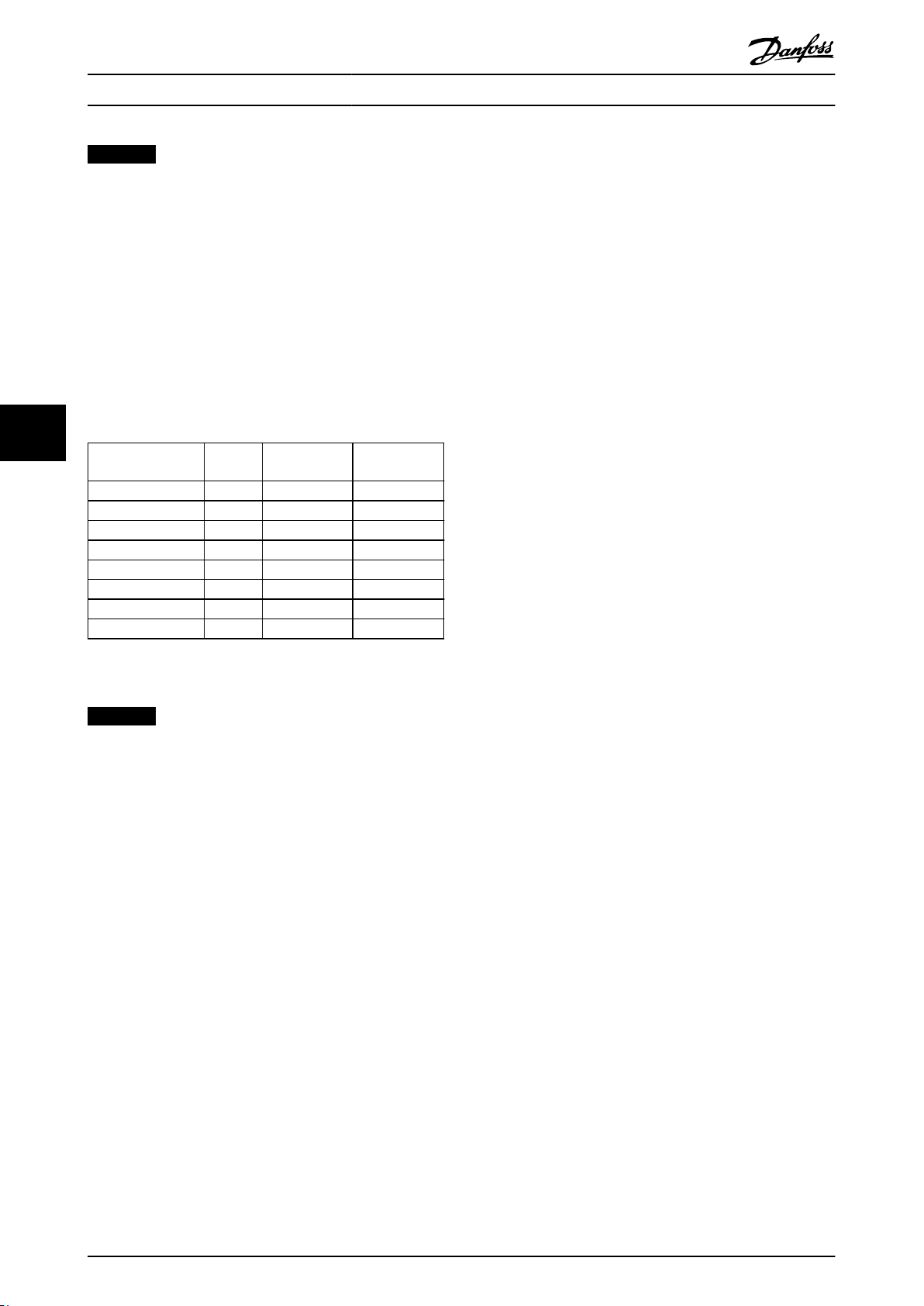
4.2.2 Parameter Settings
Ex-e and Ex-n-specic parameters
Function Setting
1-90 Motor Thermal Protection
1-94 ATEX ETR cur.lim. speed
reduction
1-98 ATEX ETR interpol. points freq.
1-99 ATEX ETR interpol points
current
1-23 Motor Frequency
4-19 Max Output Frequency
4-18 Current Limit
5-15 Terminal 33 Digital Input
Parameter 5-19 Terminal 37 Safe
Stop
14-01 Switching Frequency
14-26 Trip Delay at Inverter Fault
Table 4.4 Parameter Settings
[20] ATEX ETR
20%
Motor nameplate
Enter the same value as for
4-19 Max Output Frequency.
Motor nameplate, possibly
reduced for long motor
cables, sine-wave lter, or
reduced supply voltage.
Forced to 150% by 1-90 [20]
[80] PTC Card 1
[4] PTC 1 Alarm
Check that the default value
fulls the requirement from
the motor nameplate. If not,
use a sine-wave lter.
0
4.3.2
Maximum Current Limit
The operation above the thermal characteristic curve is
permitted for a limited period of 60 s.
The actual thermal overload is calculated based on the ETR
function selected in 1-90 Motor Thermal Protection and is
displayed in 16-18 Motor Thermal.
Running above the characteristic curve for more than 50 s
triggers Warning 163 ATEX ETR cur.lim. warning. Congure
the reaction for operating in Ex-e and Ex-n current limits in
1-94 ATEX ETR cur.lim. speed reduction.
0%: The frequency converter does not change
•
anything besides issuing Warning 163 ATEX ETR
cur.lim.warning.
>0%: The frequency converter issues Warning 163
•
ATEX ETR cur.lim.warning and reduces motor
speed following ramp 2 (parameter group 3–5*
Ramp 2).
Example:
Actual reference = 200 RPM
1-94 ATEX ETR cur.lim. speed reduction = 20%
Resulting reference = 160 RPM
Operating above the characteristic curve for more than
60 s within a period of 600 s triggers Alarm 164 ATEX ETR
cur.lim., and the frequency converter trips.
Operation above 150% nominal motor current trips the
frequency converter after 1 s with Alarm 164 ATEX ETR
cur.lim.
Operation above 180% nominal motor current immediately
trips the frequency converter with Alarm 164 ATEX ETR
cur.lim.
4.3
Parameter Set-up for Ex-e and Ex-n
Motors
4.3.1 Maximum Current
To activate the ATEX ETR monitor function, set 1-90 Motor
Thermal Protection to [20] ATEX ETR. This enables 1-94 ATEX
ETR cur.lim. speed reduction, 1-98 ATEX ETR interpol. points
freq., and 1-99 ATEX ETR interpol points current, and limits
4-18 Current Limit to 150%.
14 Danfoss A/S © 01/2015 All rights reserved. MG33V302
rst start-up (power-up), the overload counter starts
After
at a value that prevents resetting the thermal load value
by power cycling. After start-up, the overload warning is
suppressed until the motor current exceeds the rated
current limit for the rst time.
4.3.3
Minimum Motor Frequency
The operation below the minimum frequency in 1-98 ATEX
ETR interpol. points freq. is allowed for a limited time only.
Running below the minimum frequency for more than 50 s
triggers Warning 165 ATEX ETR freq.lim.warning.

Commissioning Operating Instructions
Operation below the minimum frequency for more than
60 s within a period of 600 s triggers Alarm 166 ATEX ETR
freq.lim.alarm. The frequency converter trips.
4.3.4 Maximum Motor Frequency
Do not exceed the maximum allowable output frequency.
The motor data sheet or nameplate shows the maximum
permissible value.
NOTICE
This value can be reduced for long motor cables, sinewave lter, or reduced supply voltage.
Un − Uloss
f
=
max
Example:
Use the result from the equation as the value set in
4-19 Max Output Frequency.
4.3.5
Thermal motor losses increase with lower switching
frequencies. Ensure that the frequency converter switching
frequency does not drop below the value stated by the
motor manufacturer.
x f n
Un
Nominal voltage = 480 V
Nominal frequency = 50 Hz
Voltage loss due to supply voltage of 450 V =
30 V
Resulting maximum frequency = 47 Hz
Minimum Switching Frequency
NOTICE
It is mandatory to compare the minimum switching
frequency requirement of the motor to the minimum
switching frequency of the frequency converter, which is
the default value in 14-01 Switching Frequency. If the
frequency converter does not meet this requirement, use
a sine-wave lter.
4.3.6 Disable Protection Mode
In protection mode, the frequency converter derates the
switching frequency below the default in 14-01 Switching
Frequency. For example, if the default value is 3 kHz, it can
derate down to 2.5 kHz, depending on EEPROM. Therefore,
disable protection mode in 14-26 Trip Delay at Inverter Fault.
More information about derating can be found in the
section Derating in the frequency converter design guide.
4.3.7
Safe Torque O Functionality
The desired Safe Torque O functionality is specied in
parameter 5-19 Terminal 37 Safe Stop. When a VLT® PTC
Thermistor Card MCB 112 is mounted, select 1 of the PTC
options to get the full benet from the alarm handling.
Options [4] PTC 1 Alarm and [5] PTC 1 Warning are relevant
when the MCB 112 is the only interrupt device using STO.
Options [6] PTC 1 & Relay A to [9] PTC 1 & Relay W/A are
relevant when other safety sensors are also connected to
STO.
Alarm: The frequency converter coasts. Reset the
•
alarm manually (via bus, digital I/O, or by pressing
[Reset]). Auto reset does not apply here. For more
details, see [4] PTC 1 Alarm in
parameter 5-19 Terminal 37 Safe Stop.
Warning: The frequency converter coasts, but
•
resumes operation when STO and the DI from
X44/10 are disabled. For more details, see [5] PTC
1 Warning in parameter 5-19 Terminal 37 Safe Stop.
Conguring a digital input in parameter group 5-1* Digital
Inputs makes it possible to give a warning/alarm that
species what triggered the Safe Torque O.
NOTICE
When selecting warning instead of alarm, automatic
restart is enabled. See Installation in Combination with
VLT® PTC Thermistor Card MCB 112 in the VLT® Frequency
Converters - Safe Torque O Operating Instructions.
Safe Torque O-related Parameter
5-19 Terminal 37 Safe Stop
To congure the Safe Torque O functionality, set this parameter.
A warning message makes the frequency converter coast the
motor and enables the automatic restart. An alarm message
makes the frequency converter coast the motor and requires a
manual restart (via a eldbus, digital I/O, or by pressing [Reset]
on the LCP). When the MCB 112 is mounted, congure the PTC
options to get the full benet from the alarm handling.
Option: Function:
[1] Safe Stop Alarm Coasts the frequency converter
when Safe Torque O is activated.
Manual reset from LCP, digital input,
or eldbus.
[3] Safe Stop
Warning
Coasts the frequency converter
when Safe Torque O is activated
(terminal 37 o). When Safe Torque
O circuit is re-established, the
frequency converter continues
without manual reset.
4 4
MG33V302 Danfoss A/S © 01/2015 All rights reserved. 15

Commissioning
VLT® PTC Thermistor Card MCB 112
5-19 Terminal 37 Safe Stop
To congure the Safe Torque O functionality, set this parameter.
A warning message makes the frequency converter coast the
motor and enables the automatic restart. An alarm message
makes the frequency converter coast the motor and requires a
manual restart (via a eldbus, digital I/O, or by pressing [Reset]
on the LCP). When the MCB 112 is mounted, congure the PTC
options to get the full benet from the alarm handling.
44
Option: Function:
[4] PTC 1 Alarm Coasts the frequency converter
when Safe Torque O is activated.
Manual reset from LCP, digital input,
or eldbus.
[5] PTC 1 Warning Coasts the frequency converter
when Safe Torque O is activated
(terminal 37 o). When Safe Torque
O circuit is re-established, the
frequency converter continues
without manual reset, unless a
digital input set to [80] PTC Card 1 is
still enabled.
[6] PTC 1 & Relay A This option is used when the PTC
option gates with a stop button
through a safety relay to terminal
37. Coasts the frequency converter
when Safe Torque O is activated.
Manual reset from LCP, digital input,
or eldbus.
[7] PTC 1 & Relay W This option is used when the PTC
option gates with a stop button
through a safety relay to terminal
37. Coasts the frequency converter
when Safe Torque O is activated
(terminal 37 o). When Safe Torque
O circuit is re-established, the
frequency converter continues
without manual reset, unless a
digital input set to [80] PTC Card 1 is
still enabled.
[8] PTC 1 & Relay
A/W
[9] PTC 1 & Relay
W/A
This option makes it possible to use
a combination of alarm and warning.
This option makes it possible to use
a combination of alarm and warning.
Function Num-
ber
No Function [0] – –
Safe Stop Alarm [1]* – Safe Stop [A68]
Safe Stop
Warning
PTC 1 Alarm [4] PTC 1 Safe Stop
PTC 1 Warning [5] PTC 1 Safe Stop
PTC 1 & Relay A [6] PTC 1 Safe Stop
PTC 1 & Relay W [7] PTC 1 Safe Stop
PTC 1 & Relay
A/W
PTC 1 & Relay
W/A
Table 4.5 Overview of Functions, Alarms, and Warnings
W means warning and A means alarm. For further information, see
Alarms and Warnings in the Troubleshooting section in the design
guide or the operating instructions.
[3] – Safe Stop [W68]
[8] PTC 1 Safe Stop
[9] PTC 1 Safe Stop
PTC Relay
–
[A71]
–
[W71]
Safe Stop [A68]
[A71]
Safe Stop [W68]
[W71]
Safe Stop [W68]
[A71]
Safe Stop [A68]
[W71]
A dangerous failure related to Safe Torque O issues Alarm
72 Dangerous Failure.
Refer to Table 6.1.
NOTICE
Selecting Auto Reset/Warning enables automatic restart
of the frequency converter.
16 Danfoss A/S © 01/2015 All rights reserved. MG33V302

130BA966.13
Digital Input
PTC
Sensor
Non-Hazardous AreaHazardous
Area
X44/
PTC Thermistor Card
MCB 112
1 2 3 4 5 6 7 8 9 10 1112
DI DI
Safe Stop
12 13 18 19 27 29 32 33 20 37
e.g. Par 5-15
Par. 5-19
Terminal 37 Safe Stop
130BA967.12
Digital Input
PTC
Sensor
Non-Hazardous AreaHazardous
Area
X44/
PTC Thermistor Card
MCB 112
1 2 3 4 5 6 7 8 9 10 11 12
Safety Device
Manual Restart
SIL 2
Safe AND Input
Safe Output
Safe Input
DI DI
Safe Stop
Par. 5-19
Terminal 37 Safe Stop
12 13 18 19 27 29 32 33 20 37
e.g. Par 5-15
Application Examples Operating Instructions
5 Application Examples
The following 2 examples show the possibilities when
using the VLT® PTC Thermistor Card MCB 112.
Example 1: Standard use
Illustration 5.1 Standard Use of MCB 112
Parameter 5-19 Terminal 37 Safe Stop
[4] PTC 1
Alarm
5-15 Terminal 33 Digital Input
If the motor temperature is too high, or if a PTC
failure occurs, the MCB 112 activates the STO.
Terminal 37 goes LOW (active), and digital input
33 goes HIGH (active). This parameter decides the
consequence of the Safe Torque O (STO). With
this selection, the frequency converter coasts and
the LCP displays Alarm 71 PTC 1 Safe Stop. Reset
the frequency converter manually from the LCP,
digital input, or eldbus when the conditions of
the PTC are acceptable again (temperature of
motor has dropped).
Example 2: Combination with other components using
STO
5 5
Illustration 5.2 More Safety Devices in Combination with STO
and MCB 112
[80] PTC
Card 1
Connects the digital input of terminal 33 in the
FC 302 to the MCB 112, which enables MCB 112
to indicate when STO has been activated from
here.
Table 5.1 Programming Example 1
Alternatively, parameter 5-19 Terminal 37 Safe Stop could be
set to [5] PTC 1 Warning, which means an automatic restart
when the conditions of the PTC circuit have returned to
acceptable. The selection depends on customer demands.
MG33V302 Danfoss A/S © 01/2015 All rights reserved. 17

Application Examples
Parameter 5-19 Terminal 37 Safe Stop
[6] PTC 1 &
Relay Alarm
55
5-15 Terminal 33 Digital Input
[80] PTC Card 1 Connects the digital input of terminal 33 to
If the motor temperature is too high, or if a
PTC failure occurs, the MCB 112 activates the
STO of the frequency converter. Terminal 37
goes LOW (active), and digital input 33 goes
HIGH (active). This parameter decides the
consequence of the Safe Torque O (STO).
With this selection, the frequency converter
coasts and the LCP displays Alarm 71 PTC 1
Safe Stop. Reset the frequency converter
manually from LCP, digital input, or
when the conditions of the PTC are
acceptable again (the motor temperature has
dropped). An emergency stop can also
activate STO. Terminal 37 goes LOW (active),
but MCB 112 X44/10 does not trigger digital
input 33 as the MCB 112 did not need to
activate the STO. Therefore, digital input 33
remains HIGH (inactive).
the MCB 112, which enables the MCB 112 to
indicate when STO has been activated from
here.
VLT® PTC Thermistor Card MCB 112
eldbus
Table 5.2 Programming Example 2
Alternatively, parameter 5-19 Terminal 37 Safe Stop could be
set to [7] PTC 1 & Relay Warning. Selecting this option
causes an automatic restart when the conditions of the
PTC circuit and/or emergency stop circuit have returned to
normal. The selection depends on customer demands. Also,
the setting of parameter 5-19 Terminal 37 Safe Stop could
be [8] PTC 1 & Relay A/W or [9] PTC 1 & Relay W/A, which is
a combination of alarms and warnings. The selection
depends on customer demands.
NOTICE
Selections [4] PTC 1 Alarm to [9] PTC 1 & Relay W/A in
parameter 5-19 Terminal 37 Safe Stop are only visible if
the MCB 112 is plugged into the B-option slot.
NOTICE
Take care that the digital input set to [80] PTC Card 1 is
not also congured as thermistor resource (motor
overload protection) in 1-93 Thermistor Resource.
18 Danfoss A/S © 01/2015 All rights reserved. MG33V302

Maintenance and Troubleshoo... Operating Instructions
6 Maintenance and Troubleshooting
6.1 Maintenance
The devices are maintenance-free. Only the manufacturer
(www.ZIEHL.de) is allowed to perform repair work. Observe
EN 60079-17 Explosive atmospheres - Part 17: Electrical
installations, inspection, and maintenance.
6.2 Troubleshooting
The resistance in the sensor circuit must have a
•
value 50 Ω <R <1500 Ω. The terminal voltage
must be <2.5 V with the resistors attached.
If terminal T1-T2 is open, the relay must shut o.
•
The terminal voltage must be approximately 9 V.
Alarm/Warning Code List
6.2.1
Para-
Num-
Table 6.1 Alarms and Warnings Directly Related to STO
1) Cannot be auto reset via 14-20 Reset Mode.
ber
68
71
72
Descrip-
tion
Safe Stop
Activated
PTC 1 Safe
Stop
Dangerous
Failure
Warning
X
X
Alarm/
Trip
1)
X
1)
X
Alarm/
Trip lock
1)
X
meter
refe-
rence
Parameter
5-19 Termi
nal 37 Safe
Stop
Parameter
5-19 Termi
nal 37 Safe
Stop
Parameter
5-19 Termi
nal 37 Safe
Stop
NOTICE
Alarm 11, Motor Thermistor overtemp. relates to
1-93 Thermistor Resource and not to the MCB 112.
Alarm 68, Safe Stop
STO has been activated. To resume normal operation,
apply 24 V DC to terminal 37, then send a reset signal (via
bus, digital I/O, or by pressing [Reset]).
Warning 68, Safe Stop
STO has been activated. Normal operation is resumed
when STO is disabled.
Warning: Automatic Restart.
Alarm 71, PTC 1 Safe Stop
STO has been activated from the MCB 112 (motor too
warm). Normal operation can be resumed when:
The MCB 112 applies 24 V DC to terminal 37
•
again (when the motor temperature reaches an
acceptable level), and
The digital input from the MCB 112 is
•
deactivated.
When that happens, send a reset signal (via bus, digital I/O,
or by pressing [Reset]).
Warning 71, PTC 1 Safe Stop
STO has been activated from the MCB 112 (motor too
warm). Normal operation can be resumed when:
The MCB 112 applies 24 V DC to terminal 37
•
again (when the motor temperature reaches an
acceptable level), and
The digital input from the MCB 112 is
•
deactivated.
Warning: Automatic Restart.
Alarm 72, Dangerous Failure
STO with trip lock. If the combination of STO commands is
unexpected, the dangerous failure-alarm is issued. This
situation occurs if the MCB 112 enables X44/10 without
STO being enabled. Furthermore, if the MCB 112 is the
only device using STO (specied by [4] PTC 1 Alarm or [5]
PTC 1 Warning in parameter 5-19 Terminal 37 Safe Stop), an
unexpected combination activates the STO without
activating the X44/10. Table 6.2 summarises the
unexpected combinations that trigger this alarm.
6 6
6.2.2 Description of Alarm Word, Warning
Word, and Extended Status Word
Bit Hex Dec
4000
0000
8000
0000
10737
41824
21474
83648
30
31
MG33V302 Danfoss A/S © 01/2015 All rights reserved. 19
Alarm
word
Safe
Stop
[A68]
Alarm
word2
PTC 1
Safe Stop
[A71]
Dangerous
Failure
[A72]
Warning
word
Safe Stop
[W68]
Warning
word2
PTC 1
Safe Stop
[W71]
Maintenance and Troubleshoo...
VLT® PTC Thermistor Card MCB 112
NOTICE
If X44/10 is activated in selection [2] Safe Stop Alarm or
[3] Safe Stop Warning, this signal is ignored. However, the
MCB 112 is still able to activate STO.
Example:
[5] PTC 1 Warning is selected in parameter 5-19 Terminal 37
Safe Stop, and X44/10 is not activated, but STO is. This is
an unexpected selection. [5] PTC 1 Warning in
parameter 5-19 Terminal 37 Safe Stop
only triggered from MCB 112.
+: Activated
-: Not activated
species that STO is
66
Function Number X44/10 (DI) STO terminal
37
PTC 1 Alarm [4] + -
- +
PTC 1 Warning [5] + -
- +
PTC 1 & Relay A [6] + PTC 1 & Relay W [7] + PTC 1 & Relay A/W [8] + PTC 1 & Relay W/A [9] + -
Table 6.2 Unexpected Combinations Triggering Alarm 72
Dangerous Failure
NOTICE
For correct and safe use of the STO function, follow the
related information and instructions in the VLT
Frequency Converters - Safe Torque O Operating
Instructions.
®
20 Danfoss A/S © 01/2015 All rights reserved. MG33V302
Technical Specications Operating Instructions
7 Technical Specications
7.1 Mains Supply
Mains supply
Rated supply voltage U
Tolerance voltage U
Power consumption <1 W
S
S
7.2 Control Inputs and Outputs
PTC thermistor connection X44/1+X44/2
Standard DIN 44081/DIN 44082
Numbers Set with 3–6 PTCs in series
Cut-out point 3.3 kΩ...3.65 kΩ...3.85 kΩ
Reclosing point 1.7 kΩ...1.8 kΩ...1.95 kΩ
Collective resistance cold sensors ≤1.65 kΩ
Terminal voltage (sensors) ≤2.5 V at R ≤3.65 kΩ, ≤9 V at R=∞
Terminal current (sensors) ≤1 mA
Short circuit 20 Ω ≤R ≤40 Ω
Power consumption ≤2 mW
24 V DC
21–28 V DC
7 7
Safe stop terminal 37, X44/12
Output PNP transistor
Logical voltage level 0–24 V DC
Low=0, PNP <4 V DC
Voltage
Current 60 mA
Logic out, X44/10
Output PNP transistor
Logical voltage level 0–24 V DC
Voltage
Current 10 mA
High=1, PNP >20 V DC
Low=0, PNP <5 V DC
High=1, PNP >10 V DC
7.3 Ambient Conditions
Environment
Rated ambient temperature range, T
Relative humidity 5–95%, without condensation
EMC - Immunity industry standard EN 61000-6-2
EMC - Emission industry standard EN 61000-6-4
Vibration resistance 10–1000 Hz 1.14 g
Shock resistance 50 g
Testing conditions
Standards EN 60947-8, EN 50178
Rated impulse voltage 6000 V
Overvoltage category III
Contamination level 2
Rated insulation voltage U
Safe separation up to U
I
I
a
-20 °C to +55 °C
690 V
500 V
MG33V302 Danfoss A/S © 01/2015 All rights reserved. 21
Technical Specications
VLT® PTC Thermistor Card MCB 112
7.4 Other Specications
Enclosure
Form 130B4065 PA 6
Dimensions (H x W x T) [mm] 82.5 x 69.5 x 29.5
Wire connection, solid wire 1 x 0.5–1.5 mm2 (AWG 20–16 solid wire)
Insulation strip length 8.5–9.5 mm
Protection rating IEC 60529 IP20
Weight ≈50 g
7.5 Safety Characteristics of the Built-in MCB 112
The safety characteristics include the connection between
output safe stop T37 (output X44/12 on MCB 112) and
terminal 37 input on the control card.
Operating
mode
77
Low
demand
mode
Table 7.1 Safety Integrity Level SIL (EN 61508)
MCB 112 MTBF SFF
Ta=40 °C
Table 7.2 Safety-related Parameters, Part 1
MCB 112 Proof test
Ta=40 °C
Table 7.3 Safety-related Parameters, Part 2
Hardware
architecture
1oo1 0 SIL 2 Type A
44
years
interval
PFD
avg
Fault
tolerance
HFT
λ
SD
96,5% 2103 x
10-9/h
1 year 3 years 5 years 10 years
3.37E-04 1.01E-03 1.68E-03 3.37E-03
λ
SU
41.8 x
10-9/h
Safety
integrity
level
λ
DD
1.23 x
10-9/h
Subsystem
device
λ
DU
81.4 x
10-9/h
Observe the proof test interval according to EN 60079-17
for electrical equipment ≤3 years.
The data of the functional safety stated in Table 7.1 to
Table 7.3 are valid for an ambient temperature of 40 °C.
Data for more ambient temperatures can be obtained by
request.
22 Danfoss A/S © 01/2015 All rights reserved. MG33V302

Index Operating Instructions
Index
A
Abbreviations........................................................................................... 6
Alarm word............................................................................................. 19
Ambient conditions...................................................................... 12, 21
Ambient temperature......................................................................... 22
Approvals................................................................................................... 5
ATEX
ETR monitor function..................................................................... 14
Certication.......................................................................................... 4
Module............................................................................................ 4, 11
Thermal monitoring function.................................................... 4, 7
Zone 1................................................................................................ 3, 5
Zone 2................................................................................................ 3, 5
Zone 21.............................................................................................. 3, 5
Zone 22.............................................................................................. 3, 5
Auto reset................................................................................................ 15
B
Block diagram........................................................................................... 5
C
Cables/Wires
Control cable, mounting............................................................... 10
Mounting control cable................................................................. 10
Permissible length.............................................................................. 9
Screened control wire....................................................................... 9
Sensor circuit wire.............................................................................. 9
Separate control wire........................................................................ 9
Certications............................................................................................. 5
Combustible dust.................................................................................... 8
Commissioning test............................................................................. 12
Conventions.............................................................................................. 6
I
Intended use............................................................................................. 3
M
Maintenance.......................................................................................... 19
Manual reset........................................................................................... 15
Marking D.................................................................................................. 3
Marking G.................................................................................................. 3
Maximum current................................................................................... 5
Minimum frequency............................................................................ 14
Minimum switching frequency.......................................................... 5
Misuse of the product........................................................................... 4
Motor
Ex-d.......................................................................................................... 4
Ex-e........................................................................................ 4, 5, 13, 14
Ex-n....................................................................................... 4, 5, 13, 14
Maximum frequency......................................................................... 5
Minimum frequency.......................................................................... 5
Monitoring............................................................................................ 4
Nominal motor current.................................................................. 14
Protection.............................................................................................. 4
Requirement........................................................................................ 5
Multi-motor application....................................................................... 5
N
Nameplate.......................................................................................... 5, 13
O
Overvoltage............................................................................................ 10
P
Protection mode................................................................................... 15
D
Dangerous failure................................................................... 16, 19, 20
Derating................................................................................................... 15
Q
Qualied personnel....................................................................... 3, 7, 8
R
E
Environment........................................................................................... 21
Ex-e current limit.................................................................................. 14
Ex-n current limit.................................................................................. 14
Explosive dust atmosphere............................................................. 3, 7
Explosive gas atmosphere............................................................... 3, 7
Extended status word......................................................................... 19
F
Frequency converter
Requirement...................................................................................... 13
MG33V302 Danfoss A/S © 01/2015 All rights reserved. 23
Release temperature........................................................................... 12
Repair work............................................................................................. 19
Resistance................................................................................................ 12
S
Safe separation........................................................................................ 4
Safe Torque O.................................................................................. 4, 16
Safe Torque O functionality........................................................... 15
Safety function...................................................................................... 12
Safety integrity level, SIL.................................................................... 22
Sensor resistance.................................................................................. 12

Index
Standards
ATEX Directive 94/9/EC..................................................................... 4
DIN 44081.................................................................................. 3, 4, 21
DIN 44082.................................................................................. 3, 4, 21
EN 50178............................................................................................. 21
EN 60079-1............................................................................................ 7
EN 60079-14................................................................................ 4, 7, 8
EN 60079-17....................................................................................... 22
EN 60079-17 Explosive atmospheres........................................ 19
EN 60079-7............................................................................................ 4
EN 60947-8..................................................................................... 3, 21
EN 61000-6-2..................................................................................... 21
EN 61000-6-4..................................................................................... 21
EN 61508............................................................................................. 22
EN ISO 12100................................................................................. 7, 11
IEC 60529................................................................................... 7, 8, 10
ISO 13849-2.......................................................................................... 7
Sticker.......................................................................................................... 4
Symbols...................................................................................................... 6
VLT® PTC Thermistor Card MCB 112
T
Terminals
Safe stop T37..................................................................................... 10
T1........................................................................................................... 12
T2........................................................................................................... 12
X44/1.................................................................................................... 21
X44/10................................................................. 4, 11, 15, 19, 20, 21
X44/12............................................................................... 4, 10, 12, 21
X44/2.................................................................................................... 21
Test............................................................................................................. 12
Testing conditions................................................................................ 21
Thermal limitation curve.................................................................... 13
Thermal overload................................................................................. 14
Thermal winding protection............................................................... 5
Tripping function............................................................................. 4, 12
Tripping temperature.......................................................................... 12
U
Unexpected combination................................................................. 20
V
Voltage drop............................................................................................. 5
W
Warning word........................................................................................ 19
24 Danfoss A/S © 01/2015 All rights reserved. MG33V302

Index Operating Instructions
MG33V302 Danfoss A/S © 01/2015 All rights reserved. 25

Danfoss can accept no responsibility for possible errors in catalogues, brochures and other printed material. Danfoss reserves the right to alter its products without notice. This also applies to
products already on order provided that such alterations can be made without subsequential changes being necessary in specications already agreed. All trademarks in this material are property
of the respective companies. Danfoss and the Danfoss logotype are trademarks of Danfoss A/S. All rights reserved.
Danfoss A/S
Ulsnaes 1
DK-6300 Graasten
vlt-drives.danfoss.com
130R0104 MG33V302 01/2015
*MG33V302*
 Loading...