

Installation Instructions
VLT® Analog I/O Option MCB 109
FC Series FC 102, FC 103, and FC 202
These installation instructions provide information about instal-
lation and use of the VLT
instructions are targeted at users already familiar with the
®
HVAC Drive FC 102, VLT® Refrigeration Drive FC 103, or
VLT
®
AQUA Drive FC 202. Read the instructions before instal-
VLT
lation and ensure that instructions for safe installation are
observed.
Additional resources
Further manuals and instructions are available for download at
www.vlt-drives.danfoss.com/Products/Detail/TechnicalDocuments---contextless/.
®
Analog I/O Option MCB 109. The
Items supplied
The VLT® Analog I/O Option MCB 109 is available in a standard
version (code number 130B1143) and in a coated version
(code number 130B1243)
Items supplied
VLT® Analog I/O Option MCB 109
•
Extended LCP (local control panel) frame (for use
•
with enclosure sizes A2, A3, B3, and B4)
Terminal covers (various sizes for use with enclosure
•
sizes A2, A3, and B4)
Product Overview
Safety
Qualied Personnel
Only
qualied
equipment. Qualied personnel is dened as trained sta, who
are authorised to install, commission, and maintain equipment,
systems, and circuits in accordance with pertinent laws and
regulations. Additionally, the personnel must be familiar with
the instructions and safety measures described in the product
specic
personnel are allowed to install or operate this
operating instructions.
WARNING
DISCHARGE TIME
The frequency converter contains DC-link capacitors, which
can remain charged even when the frequency converter is
not powered. Failure to wait the specied time after power
has been removed before performing service or repair work,
could result in death or serious injury.
1. Stop the motor.
2. Disconnect the AC mains, permanent magnet type
motors, and remote DC-link power supplies,
including battery back-ups, UPS, and DC-link
connections to other frequency converters.
3. Wait for the capacitors to discharge fully before
performing any service or repair work. The duration
of waiting time is specied in Ta bl e 2 .1 to Tabl e 2 .3 .
The VLT® Analog I/O Option MCB 109 increases the number of
available inputs and outputs at the frequency converter.
Additionally, it provides a battery back-up for the built-in clock
function in the frequency converter.
Features
3 analog inputs, each
•
and temperature input.
Connection of 0–10 V analog signals as well as
•
PT1000 and NI1000 temperature inputs.
3 analog outputs each congurable as 0–10 V
•
outputs.
Battery back-up for the built-in clock function in the
•
frequency converter. The back-up battery typically
lasts for 10 years, depending on environment.
congurable
as both voltage
Danfoss A/S © 04/2015 All rights reserved. MI38B302
Volt age [V]
4715
200-240 1.1–3.7 kW – 5.5–45 kW
380-480 1.1–7.5 kW – 11–90 kW
525-600 1.1–7.5 kW – 11–90 kW
525-690 – 1.1–.5 kW 11–90 kW
High voltage may be present even when the warning LED indicator
lights are o.
Tab le 2.1 Dis ch ar ge Time, VLT® HVAC Drive FC 102
Minimum waiting time (minutes)
Installation Instructions
®
Analog I/O Option MCB 109
VLT
FC Series FC 102, FC 103, and FC 202
Voltage [V]
415
200–240 1.1–3.7 kW 5.5–45 kW
380–500 1.1–7.5 kW 11–90 kW
525–600 1.1–7.5 kW 11–90 kW
High voltage may be present even when the warning LED indicator
lights are o.
Table 2.2 Discharge Time, VLT® Refrigeration Drive FC 103
Voltage [V]
4715
200–240 0.25–3.7 kW – 5.5–45 kW
380–480 0.37–7.5 kW – 11–90 kW
525–600 0.75–7.5 kW – 11–90 kW
525–690 – 1.1–7.5 kW 11–90 kW
High voltage may be present even when the warning LED indicator
lights are o.
Table 2.3 Discharge Time, VLT® AQUA Drive FC 202
Installation
Minimum waiting time (minutes)
Minimum waiting time (minutes)
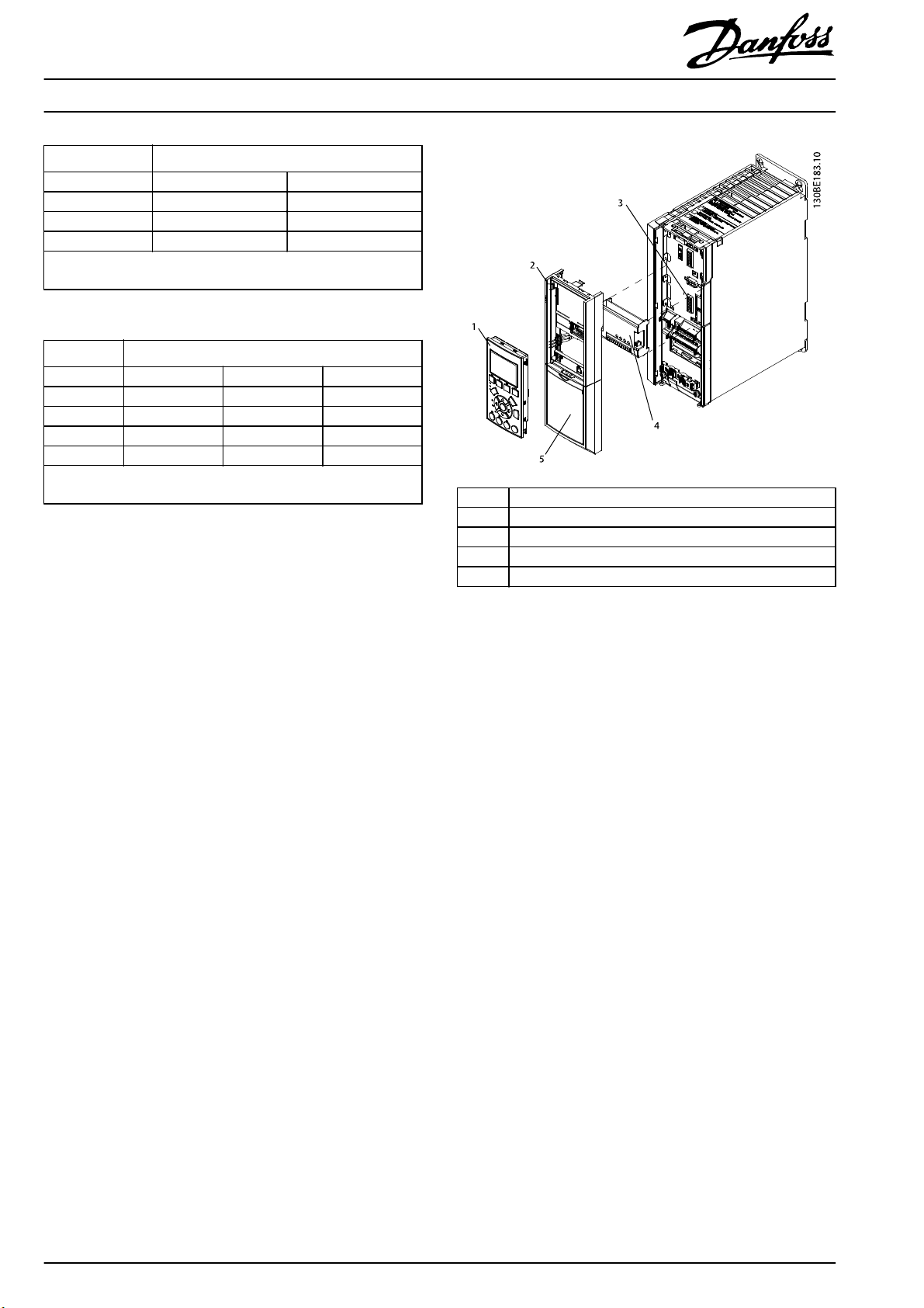
1LCP
2Terminal cover
3Slot B
4Option
5LCP frame
The installation procedure depends on the enclosure size of
the frequency converter.
Enclosure Sizes A2, A3, B3, and B4
1. Remove the LCP (local control panel), the terminal
cover, and the LCP frame from the frequency
converter.
2. Fit the option into slot B.
3. Connect the control cables and relieve the cable. See
Illustration 5.1 for details about wiring.
4. Remove the knock-out in the extended LCP frame
(supplied).
5. Fit the extended LCP frame and terminal cover on
the frequency converter.
6. Fit the LCP or blind cover in the extended LCP frame.
7. Connect power to the frequency converter.
Illustration 3.1 Installation in Enclosure Sizes A2, A3, B3, and B4
2
Danfoss A/S © 04/2015 All rights reserved. MI38B302

Installation Instructions
®
Analog I/O Option MCB 109
VLT
FC Series FC 102, FC 103, and FC 202
Enclosure Sizes A5, B1, B2, C, D, E, and F
1. Remove the LCP (local control panel) and the LCP
cradle.
2. Fit the option card into slot B.
3. Connect the control cables and relieve the cable. See
Illustration 5.1 for details about wiring.
4. Fit the cradle on the frequency converter.
5. Fit the LCP in the cradle.
Input X42/5. Refer to the programming guide, for
further details about programming of analog inputs.
To read the analog input values, go to parameter
•
group 18-3* Inputs & Outputs.
Analog Outputs
Analog outputs are used as voltage outputs.
Outputs are scalable by parameters for each output. VLT
Analog I/O Option MCB 109 analog output parameter options
are identical to the parameter options for the built-in analog
outputs of the frequency converter.
Conguring
To congure the analog outputs, go to parameter
•
groups for set-up: 26-4* Analog Out X42/7, 26-5*
Analog Out X42/9, and 26-6* Analog Out X42/11.
To read analog output values, go to parameter group
•
18-3* Inputs & Outputs.
®
Real-time Clock Back-up
1LCP
2LCP cradle
3Option
4Slot B
Illustration 3.2 Installation in Enclosure Sizes A5, B1, B2, C, D, E,
and F
Conguration
Analog Inputs
Analog inputs can be used as:
Voltage input.
•
Inputs are scalable by parameters for each input.
Temperature sensor input.
•
Input scaling is preset to necessary signal level for
specied
out value (°C or °F).
temperature span. Optional feedback read-
No further
I/O Option MCB 109 as a battery back-up.
The back-up battery typically lasts for 10 years, when the
frequency converter is operating at 40 °C ambient
temperature. If the battery pack back-up fails, replace the
analog I/O option.
conguration
is required to use the VLT® Analog
Conguring
To congure the analog inputs, go to parameter
•
groups 26-0* Analog I/O Mode, 26-1* Analog Input
X42/1, 26-2* Analog Input X42/3, and 26-3* Analog
MI38B302 Danfoss A/S © 04/2015 All rights reserved.
3

Specications
Block diagram
Specications
Used as
temperature sensor
input
Number of inputs 3 3
Terminal X42/1–6 X42/1–6
Voltage range – 0–10 V DC
Current range 0/4–20 mA (voltage
input 0–10 V)
Tem perat ur e senso r
Ω
at 0 °C)
(1000
– Pt1000 (according to
Accuracy
Tem perat ur e range
Resolution 11 bits 10 bits
Sampling 3 Hz 2.4 Hz
Maximum load –
Impedance –
Table 5.1 Analog Inputs
Ni1000 (according to
DIN 43760)
IEC 60751)
°C ±
1 Kelvin
-50
+150
°C ±
2 Kelvin
-50
°
C to +150 °C
Used as voltage input
–
–
–
0.2% of full scale at
calculated temperature
±
20 V continuously
5 k
Ω
Illustration 5.1 Block Diagram for VLT® Analog I/O Option MCB 109
Mounted in the Frequency Converter.
Number of outputs 3
Voltage level at analog output 0–10 V DC
Resolution 11 bits
Linearity 1% of full scale
Maximum load 1 mA
Table 5.2 An alog Outp ut s
Danfoss can accept no responsibility for possible errors in catalogues, brochures and other printed material. Danfoss reserves the right to alter its products without notice. This also applies to products already on
order provided that such alterations can be made without subsequential changes being necessary in specifications already agreed. All trademarks in this material are property of the respective companies. Danfoss
and the Danfoss logotype are trademarks of Danfoss A/S. All rights reserved.
Danfoss A/S
Ulsnaes 1
DK-6300 Graasten
vlt-drives.danfoss.com
MI38B302130R0322 04/2015
*MI38B302*
 Loading...