

Page 1

Installation Guide
VLT® 24 V DC Supply MCB 107
VLT® Series FC 102, FC 103, FC 202, and FC 301/FC
302
1 Scope of Delivery, Safety, and Installation
1.1 Purpose of the Manual
This installation guide describes the installation of the VLT® 24 V DC Supply MCB 107.
1.2 Purpose of the VLT® 24 V DC Supply MCB 107
VLT® 24 V DC Supply MCB 107 option is a low voltage supply to the control card or any option card installed. This option keeps the
control section (including parameter configurations) and any installed option alive during a power failure.
NOTICE
External power supply
To achieve the intended functionality, an external 24 V DC supply as specified below has to be connected to the terminals of
the option.
Specifications for VLT 24 V DC Supply MCB 107
Specification Value
Input voltage range 24 V DC ±15% (maximum 37 V for 10 s)
Maximum input current 2.2 A
Average input current for FC 301/FC 302 0.9 A
Maximum cable length 75 m (246 ft)
Input capacitance load <10 uF
Power-up delay <0.6 s
Connection terminals
• Terminal 35: - external 24 V DC supply
• Terminal 36: + external 24 V DC supply
Danfoss A/S © 2018.11
AN287957936346en-000101 / 130R0308 | 1
Page 2
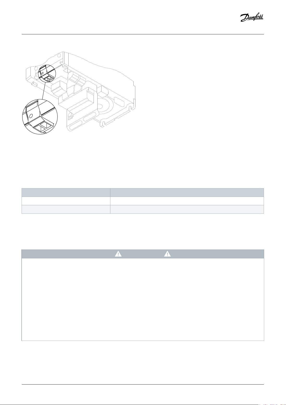
35
36
35
36
e30ba028.11
Installation Guide | VLT® 24 V DC Supply MCB 107
Illustration 1: Connection to MCB 107 on Enclosure Sizes A2 and A3
1.3 Items Supplied
Scope of Delivery, Safety, and Installation
The VLT® 24 V DC Supply MCB 107 is available in 2 versions: Standard and coated.
Table 1: Ordering Numbers
Version Ordering number
Standard 130B1108
Coated 130B1208
1.4 Safety Instructions
For important information about safety precautions for installation, refer to the product-specific operating guide.
WARNING
DISCHARGE TIME
The drive contains DC-link capacitors, which can remain charged even when the drive is not powered. High voltage can be
present even when the warning indicator lights are off.
Failure to wait the specified time after power has been removed before performing service or repair work could result in death
or serious injury.
Stop the motor.
-
Disconnect AC mains, permanent magnet type motors, and remote DC-link supplies, including battery back-ups, UPS, and
-
DC-link connections to other drives.
Wait for the capacitors to discharge fully. The minimum waiting time is specified in the table Discharge time and is also
-
visible on the nameplate on top of the drive.
Before performing any service or repair work, use an appropriate voltage measuring device to make sure that the capacitors
-
are fully discharged.
2 | Danfoss A/S © 2018.11
AN287957936346en-000101 / 130R0308
Page 3

Installation Guide | VLT® 24 V DC Supply MCB 107
Table 2: Discharge Time, VLT® HVAC Drive FC 102 and VLT® Refrigeration Drive FC 103
Voltage [V] Minimum waiting time (minutes)
4 7 15
200–240 1.1–3.7 kW (1.5–5 hp) – 5.5–45 kW (7.5–60 hp)
380–480 1.1–7.5 kW (1.5–10 hp) – 11–90 kW (15–125 hp)
525–600 1.1–7.5 kW (1.5–10 hp) – 11–90 kW (15–125 hp)
525–690 – 1.1–7.5 kW (1.5–10 hp) (FC 102 only) 11–90 kW (15–125 hp) (FC 102 only)
Table 3: Discharge Time, VLT® AQUA Drive FC 202
Voltage [V] Minimum waiting time (minutes)
4 7 15
200–240 0.25–3.7 kW (0.34–5 hp) – 5.5–45 kW (7.5–60 hp)
380–480 0.37–7.5 kW (0.5–10 hp) – 11–90 kW (15–125 hp)
525–600 0.75–7.5 kW (1.0–10 hp) – 11–90 kW (15–125 hp)
Scope of Delivery, Safety, and Installation
525–690 – 1.1–7.5 kW (1.5–10 hp) 11–90 kW (15–125 hp)
Table 4: Discharge Time, VLT® AutomationDrive FC 301/FC 302
Voltage [V] Minimum waiting time (minutes)
4 7 15
200–240 0.25–3.7 kW (0.34–5 hp) – 5.5–37 kW (7.5–50 hp)
380–500 0.25–7.5 kW (0.34–10 hp) – 11–75 kW (15–100 hp)
525–600 0.75–7.5 kW (1–10 hp) – 11–75 kW (15–100 hp)
525–690 – 1.5–7.5 kW (2–10 hp) 11–75 kW (15–100 hp)
1.5 Installing the D-Option
Prerequisites:
The following tools are required for installing the option:
• Torx 10 screwdriver.
• Flat-head screwdriver.
Danfoss A/S © 2018.11
AN287957936346en-000101 / 130R0308 | 3
Page 4

34
5
e30bg046.10
1
2
Installation Guide | VLT® 24 V DC Supply MCB 107
Scope of Delivery, Safety, and Installation
Procedure
1. Disconnect power to the drive.
2. Disconnect power to the live part connections on the relay terminals.
3. Remove the LCP or the blind cover.
4. Remove the terminal cover.
5. Remove the control cables.
6. Remove the cable decoupling plate.
For enclosure sizes A2 and A3, also remove the plastic cover underneath the decoupling plate (if installed).
7. Insert the option in the D-option slot.
8. Mount the cable decoupling plate.
9. Connect the control cables and relieve the cables with the enclosed cable strips.
10. Attach the terminal cover and the LCP, or the blind cover.
11. Connect power to the drive.
Example:
1 LCP
3 Cable decoupling plate
5 D-option slot
Illustration 2: Installing a D-Option in an A2/A3 Enclosure
4 | Danfoss A/S © 2018.11
2 Terminal cover
4 D-option
AN287957936346en-000101 / 130R0308
Page 5

Installation Guide | VLT® 24 V DC Supply MCB 107
Scope of Delivery, Safety, and Installation
| Danfoss A/S © 2018.11
5
AN287957936346en-000101 / 130R0308
Page 6

Installation Guide | VLT® 24 V DC Supply MCB 107
Scope of Delivery, Safety, and Installation
Danfoss can accept no responsibility for possible errors in catalogues, brochures and other printed material. Danfoss reserves the right to alter its products without notice. This also applies to products
already on order provided that such alterations can be made without subsequential changes being necessary in specifications already agreed. All trademarks in this material are property of the respective
companies. Danfoss and the Danfoss logotype are trademarks of Danfoss A/S. All rights reserved.
Danfoss A/S
Ulsnaes 1
DK-6300 Graasten
vlt-drives.danfoss.com
Danfoss A/S © 2018.11
MI33B
302
*MI33B302
*
AN287957936346en-000101/ 130R0308
 Loading...