

Page 1
Installation Instructions
Encoder Option MCB 102
®
VLT
AutomationDrive FC 360
1.1.1 Introduction
The encoder module can be used as feedback source for
closed loop speed control (7-00 Speed PID Feedback Source).
Configure encoder option in parameter group 17-** Feedback
Option.
Used for
VVC+ closed loop
•
Incremental encoder 5 V TTL type, RS-422, max. frequency: 410 kHz
Incremental encoder 1 Vpp, sine-cosine
Table 1.1 Supported Encoder Types/Specifications
1.1.2 Safety Instructions
WARNING
DISCHARGE TIME
The frequency converter contains DC-link capacitors, which
can remain charged even when the frequency converter is
not powered. Failure to wait the specified time after power
has been removed before performing service or repair work,
could result in death or serious injury.
1. Stop the motor.
2. Disconnect AC mains, permanent magnet type
motors, and remote DC-link power supplies,
including battery back-ups, UPS, and DC-link
connections to other frequency converters.
3. Wait for the capacitors to discharge fully, before
performing any service or repair work. The duration
of waiting time is specified in Table 1.2.
1.1.3 Items Supplied
Encoder Option MCB 102
•
NOTICE
For J1-J5 enclosure types, a terminal cover must be ordered
separately. For J6 and J7 enclosure types, no separate
terminal covers are needed.
Enclosure Code number
J1 132b0263
J2 132b0265
J3 132b0266
J4 132b0267
J5 132b0268
Table 1.3 Terminal Cover Code Numbers
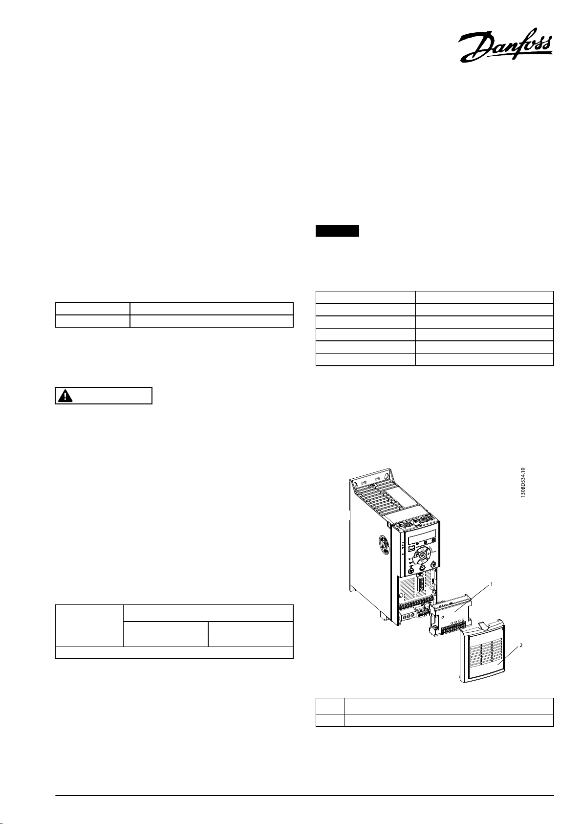
1.1.4 Mounting the Option
Mount the option according to Illustration 1.1 and
Illustration 1.2.
Voltage [V]
Minimum waiting time (minutes)
415
380-480 0.37-7.5 kW 11-75 kW
High voltage may be present even when the warning LEDs are off!
Table 1.2 Discharge Time
Danfoss A/S © Rev. 2014-03-04 All rights reserved. MI06H202
1Option
2Terminal cover
Illustration 1.1 Frequency Converter, Option and Terminal Cover
Page 2
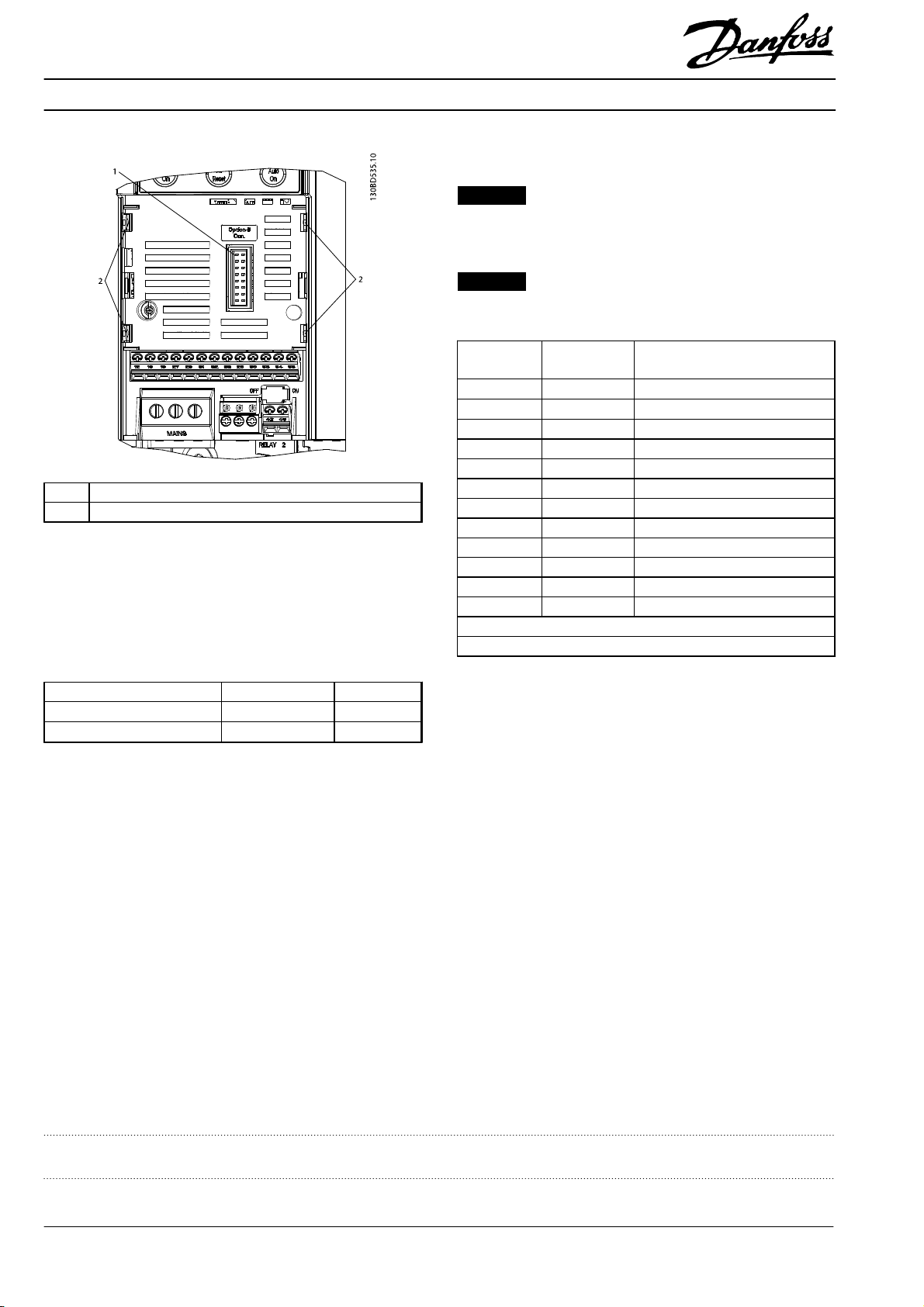
1.1.6 Electrical Installation
NOTICE
Supply the encoder through the MCB 102. Avoid to use
external power supply for the encoder.
NOTICE
Max. cable length for incremental encoder 150 m.
1 Connector
2 Metal clamps
Illustration 1.2 Connector and Metal Clamps
1.1.5 Ambient Working Temperature
For ambient working temperature af full load, see Table 1.4.
Standard Control Card
Profibus or ProfiNet
Table 1.4 Ambient Temperature
* Some types can reach 50
Guide.
Without MCB With MCB
45-50
°
C* 45 °C
45
°
C40
°
C, see VLT® AutomationDrive FC 360 Design
°
C
X31 Incremental
Encoder
1 NC 24 V Output (21-25 V, I
2NC8 V Output (7-12 V, I
3 5 VCC 5 V Output (5 V ± 5%, I
4GNDGND
5 A input A input
6 A inv input A inv input
7 B input B input
8 B inv input B inv input
9 Z input Z input OR +Data RS-485
10 Z inv input Z input OR -Data RS-485
11 NC Future use
12 NC Future use
Max. 5 V on X31.5-12
* Supply for encoder: see data on encoder
Table 1.5 Connector Designation X31
Description
max
: 200 mA)
max
max
:125 mA)
: 200 mA)
Danfoss can accept no responsibility for possible errors in catalogues, brochures and other printed material. Danfoss reserves the right to alter its products without notice. This also applies to products already on
order provided that such alterations can be made without subsequential changes being necessary in specifications already agreed. All trademarks in this material are property of the respective companies. Danfoss
and the Danfoss logotype are trademarks of Danfoss A/S. All rights reserved.
Danfoss A/S
Ulsnaes 1
DK-6300 Graasten
www.danfoss.com/drives
MI06H202132R0211 Rev. 2014-03-04
*MI06H202*
 Loading...