


MAKING MODERN LIVING POSSIBLE
Installation Guide
VLT® BACnet/IP MCA 125
VLT® HVAC Drive FC 102
vlt-drives.danfoss.com


Contents Installation Guide
Contents
1 Introduction
1.1 Purpose of the Manual
1.2 Additional Resources
1.3 Product Overview
1.4 Approvals and Certications
1.5 Disposal
1.6 Symbols, Abbreviations, and Conventions
2 Safety
2.1 Safety Symbols
2.2 Qualied Personnel
2.3 Safety Precautions
3 Installation
3.1 Safety Instructions
3.2 EMC-compliant Installation
3.3 Grounding
3.4 Cable Routing
2
2
2
2
2
2
3
4
4
4
4
6
6
6
6
6
3.5 Topology
3.5.1 Topology Types 7
3.5.1.1 Star Topology 7
3.5.1.2 Line Topology 7
3.5.1.3 Ring/Redundant Topology 8
3.5.1.4 Recommended Design Rules 8
3.6 Mounting
3.7 Electrical Installation
3.8 Reassembling the Cover
3.9 Applying Power
3.10 Checking Network Cabling
4 Troubleshooting
4.1 Warnings and Alarms
4.2 Troubleshooting
4.2.1 LED Status 13
4.2.2 No Communication with the Frequency Converter 14
7
8
10
11
11
12
13
13
13
Index
MG92K102 Danfoss A/S © 05/2016 All rights reserved. 1
15

Introduction
VLT® BACnet/IP MCA 125
11
1 Introduction
1.1 Purpose of the Manual
This installation guide provides information for the quick
installation of a VLT® BACnet/IP MCA 125 option in a VLT
frequency converter.
The installation guide is intended for use by qualied
personnel. Users are assumed to be familiar with:
VLT® frequency converter.
•
BACnet/IP technology.
•
BMS controller that is used as a master in the
•
system.
Read the instructions before installation and ensure that
the instructions for safe installation are observed.
VLT® is a registered trademark.
BACnet® is a registered trademark of ASHRAE.
1.2 Additional Resources
Resources available for the frequency converters and
optional equipment:
The relevant frequency converter operating
•
instructions provide the necessary information for
getting the frequency converter up and running.
The relevant frequency converter design guide
•
provides detailed information about capabilities
and functionality to design motor control
systems.
The relevant frequency converter programming
•
guide provides greater detail on working with
parameters and many application examples.
The VLT® BACnet/IP MCA 125 Installation Guide
•
provides information about installing the
BACnet/IP and troubleshooting.
®
The VLT
•
provides information about conguring the
system, controlling the frequency converter,
parameter access, programming, troubleshooting,
and some typical application examples.
Supplementary publications and manuals are available
from Danfoss. See vlt-drives.danfoss.com/Support/Technical-
Documentation/ for listings.
BACnet/IP MCA 125 Programming Guide
The BACnet/IP interface is designed to communicate with
any system complying with the BACnet over Ethernet or
®
BACnet/IP standard. BACnet/IP provides users with the
network protocols to deploy standard Ethernet technology
for manufacturing and building automation applications
while enabling Internet and enterprise connectivity.
VLT® BACnet/IP MCA 125 is intended for use with:
VLT® HVAC Drive FC 102
•
1.3.2 Items Supplied
When the eldbus option is not factory-mounted, the
following items are supplied:
Fieldbus option
•
LCP cradle
•
Front covers (in various sizes)
•
Stickers
•
Accessories bag
•
Strain relief (only for A1 and A2 enclosures)
•
Installation guide
•
Approvals and Certications
1.4
More approvals and certications are available. For more
information, contact a local Danfoss partner.
Disposal
1.5
Do not dispose of equipment containing
electrical components together with
domestic waste.
Collect it separately in accordance with
local and currently valid legislation.
Product Overview
1.3
1.3.1 Intended Use
This installation guide relates to BACnet/IP interface.
Ordering number:
134B1586 (conformal coated).
•
2 Danfoss A/S © 05/2016 All rights reserved. MG92K102

Introduction Installation Guide
1.6 Symbols, Abbreviations, and
Conventions
Abbreviation Denition
BMS Building management system
TM
CIP
DHCP Dynamic host conguration protocol
EMC Electromagnetic compatibility
IP Internet protocol
LCP Local control panel
LED Light emitting diode
MAR Major recoverable fail
MAU Major unrecoverable fail
PC Personal computer
PLC Programmable logic controller
TCP Transmission control protocol
Table 1.1 Symbols and Abbreviations
Conventions
Numbered lists indicate procedures.
•
Bullet lists indicate other information and
•
description of illustrations.
Italicized text indicates the following:
•
All dimensions are in metric values (imperial
•
values in brackets).
An asterisk (*) indicates the default setting of a
•
parameter.
Common industrial protocol
- Cross-reference.
- Link.
- Parameter name.
- Parameter option.
- Parameter group name.
1 1
MG92K102 Danfoss A/S © 05/2016 All rights reserved. 3

Safety
VLT® BACnet/IP MCA 125
2 Safety
22
2.1 Safety Symbols
The following symbols are used in this guide:
WARNING
Indicates a potentially hazardous situation that could
result in death or serious injury.
CAUTION
Indicates a potentially hazardous situation that could
result in minor or moderate injury. It can also be used to
alert against unsafe practices.
NOTICE
Indicates important information, including situations that
can result in damage to equipment or property.
2.2 Qualied Personnel
Correct and reliable transport, storage, installation,
operation, and maintenance are required for the troublefree and safe operation of the frequency converter. Only
qualied personnel are allowed to install or operate this
equipment.
Qualied personnel are dened as trained sta, who are
authorized to install, commission, and maintain equipment,
systems, and circuits in accordance with pertinent laws and
regulations. Also, the qualied personnel must be familiar
with the instructions and safety measures described in this
installation guide.
Safety Precautions
2.3
WARNING
HIGH VOLTAGE
Frequency converters contain high voltage when
connected to AC mains input, DC supply, or load sharing.
Failure to perform installation, start-up, and maintenance
by qualied personnel can result in death or serious
injury.
Only qualied personnel must perform instal-
•
lation, start-up, and maintenance.
WARNING
UNINTENDED START
When the frequency converter is connected to AC mains,
DC supply, or load sharing, the motor may start at any
time. Unintended start during programming, service, or
repair work can result in death, serious injury, or
property damage. The motor can start with an external
switch, a eldbus command, an input reference signal
from the LCP or LOP, via remote operation using MCT 10
Set-up Software, or after a cleared fault condition.
To prevent unintended motor start:
Press [O/Reset] on the LCP before
•
programming parameters.
Disconnect the frequency converter from the
•
mains.
Completely wire and assemble the frequency
•
converter, motor, and any driven equipment
before connecting the frequency converter to
AC mains, DC supply, or load sharing.
WARNING
DISCHARGE TIME
The frequency converter contains DC-link capacitors,
which can remain charged even when the frequency
converter is not powered. High voltage can be present
even when the warning LED indicator lights are o.
Failure to wait the specied time after power has been
removed before performing service or repair work can
result in death or serious injury.
Stop the motor.
•
Disconnect AC mains and remote DC-link
•
supplies, including battery back-ups, UPS, and
DC-link connections to other frequency
converters.
Disconnect or lock PM motor.
•
Wait for the capacitors to discharge fully. The
•
minimum waiting time is specied in the
chapter Safety in the operating instructions
supplied with the frequency converter.
Before performing any service or repair work,
•
use an appropriate voltage measuring device to
make sure that the capacitors are fully
discharged.
4 Danfoss A/S © 05/2016 All rights reserved. MG92K102

Safety Installation Guide
WARNING
LEAKAGE CURRENT HAZARD
Leakage currents exceed 3.5 mA. Failure to ground the
frequency converter properly can result in death or
serious injury.
Ensure the correct grounding of the equipment
•
by a certied electrical installer.
WARNING
EQUIPMENT HAZARD
Contact with rotating shafts and electrical equipment
can result in death or serious injury.
Ensure that only trained and qualied personnel
•
perform installation, start-up, and maintenance.
Ensure that electrical work conforms to national
•
and local electrical codes.
Follow the procedures in this guide.
•
2 2
CAUTION
INTERNAL FAILURE HAZARD
An internal failure in the frequency converter can result
in serious injury when the frequency converter is not
properly closed.
Ensure that all safety covers are in place and
•
securely fastened before applying power.
MG92K102 Danfoss A/S © 05/2016 All rights reserved. 5

130BD866.11
≥200 mm (7.9 in)
2
1
Installation
3 Installation
3.1 Safety Instructions
VLT® BACnet/IP MCA 125
33
See chapter 2 Safety for general safety instructions.
3.2 EMC-compliant Installation
To obtain an EMC-compliant installation, follow the
instructions provided in the relevant frequency converter
operating instructions and design guide. Refer to the
BACnet/IP master manual from the BMS supplier for further
installation guidelines.
3.3 Grounding
Ensure that all stations connected to the eldbus
•
network are connected to the same ground
potential. When there are long distances between
the stations in a eldbus network, connect the
individual station to the same ground potential.
Install equalizing cables between the system
components.
Establish a grounding connection with low HF
•
impedance, for example by mounting the
frequency converter on a conductive backplate.
Keep the ground wire connections as short as
•
possible.
Electrical contact between the cable screen and
•
the frequency converter enclosure or ground is
not allowed in Ethernet installations. The RJ45
connector of the Ethernet interface provides an
electrical path for the burst transient to ground.
To reduce burst transient, use high-strand wire.
•
1 Ethernet cable
2
90° crossing
Illustration 3.1 Cable Routing
3.4
NOTICE
EMC INTERFERENCE
Use shielded cables for motor and control wiring, and
separate cables for eldbus communication, motor
wiring, and brake resistor. Failure to isolate eldbus
communication, motor, and brake resistor cables can
result in unintended behavior or reduced performance.
Minimum 200 mm (7.9 in) clearance between power,
motor, and control cables is required. For power sizes
above 315 kW (450 hp), increase the minimum distance
to 500 mm (20 in).
NOTICE
When the eldbus cable crosses a motor cable or a brake
resistor cable, ensure that the cables cross at an angle of
90°.
6 Danfoss A/S © 05/2016 All rights reserved. MG92K102
Cable Routing

130BE799.10
AutomationDrive
VLT
AutomationDrive
VLT
AutomationDrive
VLT
AutomationDrive
VLT
AutomationDrive
VLT
AutomationDrive
VLT
AutomationDrive
VLT
130BE800.10
Installation Installation Guide
3.5 Topology
3.5.1 Topology Types
The BACnet/IP MCA 125 option features a built-in Ethernet
switch with 2 Ethernet RJ45 connectors. Where the
enclosure protection rating if higher than IP2x, the
frequency converter may be equipped with two M12
connectors instead.
The module enables the connection of several BACnet/IP
options in a line topology as an alternative to a traditional
star topology.
The 2 ports are equal. If only 1 connector is used, either
port can be used.
3.5.1.1 Star Topology
Set the update time as shown in Table 3.1. The numbers
given are typical values and can vary from installation to
installation.
Numbers of frequency converters
connected in series
<8 2
8–16 4
16–32 8
>32 Large jitter can occur.
Table 3.1 Minimum Update Time
Minimum update time [ms]
3 3
Illustration 3.2 Star Topology
3.5.1.2 Line Topology
In many installations, line topology enables simpler cabling
and the use of smaller or fewer Ethernet switches. The
BACnet/IP interface supports line topology with its 2 ports
and built-in Ethernet switch.
When line topology is used, take precautions to avoid
timeout in the BMS when more than 8 frequency
converters are installed in series. Each frequency converter
in the network adds a small delay to the communication
due to the built-in Ethernet switch. When the update time
is too short, the delay can lead to a timeout in the BMS.
Illustration 3.3 Line Topology
NOTICE
In line topology, activate the built-in switch by powering
all frequency converters, either by mains or a 24 V DC
option card.
NOTICE
Installing frequency converters of dierent power sizes in
line topology may result in unwanted power-o behavior
when using control word timeout (parameter 8-02 Control
Word Source to parameter 8-06 Reset Control Word
Timeout). Mount the frequency converters with the
longest discharge time rst in the line topology. In
normal operation, the frequency converters with bigger
power sizes have a longer discharge time.
MG92K102 Danfoss A/S © 05/2016 All rights reserved. 7

130BE801.10
AutomationDrive
VLT
AutomationDrive
VLT
AutomationDrive
VLT
AutomationDrive
VLT
AutomationDrive
VLT
AutomationDrive
VLT
AutomationDrive
VLT
AutomationDrive
VLT
AutomationDrive
VLT
AutomationDrive
VLT
AutomationDrive
VLT
AutomationDrive
VLT
AutomationDrive
VLT
AutomationDrive
VLT
Max. 32 drives
130BE802.10
Installation
VLT® BACnet/IP MCA 125
3.5.1.3 Ring/Redundant Topology
3.5.1.4 Recommended Design Rules
Pay special attention to active network
•
components when designing an Ethernet
network.
33
For line topology, a small delay is added with
•
each additional switch in the line. For more
information, see Table 3.1.
Do not connect more than 32 frequency
•
converters in series. To prevent unstable or faulty
communication, set the timing, if this limit is
exceeded.
Illustration 3.4 Ring/Redundant Topology
Ring topology can increase the availability of an Ethernet
network.
For ring topology:
Install a special switch (redundancy manager)
•
between the BMS controller and the frequency
converters.
Congure the redundancy manager switch to
•
clearly dene the ports that connect to the ring.
When the ring is closed, the main redundancy manager
tests the ring for detects. If the redundancy manager
detects a fault in the ring, it recongures the ring into 2
lines instead. The transition time from ring topology into 2
lines can vary from 200 ms up to several seconds
depending on the components installed in the ring. Set
the timing of the BMS controller to ensure that the
transition time does not lead to a timeout fault.
NOTICE
For ring/redundant topology, ensure that the redundancy
manager switch supports the detection of loss of line
topology. The switch inside the BACnet/IP interface does
not support this detection, as the redundancy manager
has to perform this task.
Illustration 3.5 Recommended Design Rules
3.6 Mounting
1. Check whether the eldbus option is already
mounted in the frequency converter. If the option
is already mounted, go to step 6.
2. Remove the LCP or blind cover from the
frequency converter.
3. Use a screwdriver to remove the front cover and
the LCP cradle.
4. Mount the eldbus option with the Ethernet port
facing upwards for top cable entry (see
Illustration 3.7), or with the Ethernet port facing
downwards for bottom cable entry (see
Illustration 3.8).
5. Remove the knockout plate from the new LCP
cradle.
6. Mount the new LCP cradle.
8 Danfoss A/S © 05/2016 All rights reserved. MG92K102

1
2
3
130BD908.10
130BD909.10
130BD925.10
130BD910.10
24
3
M12 PIN# RJ45
8
1
1. . . . . .
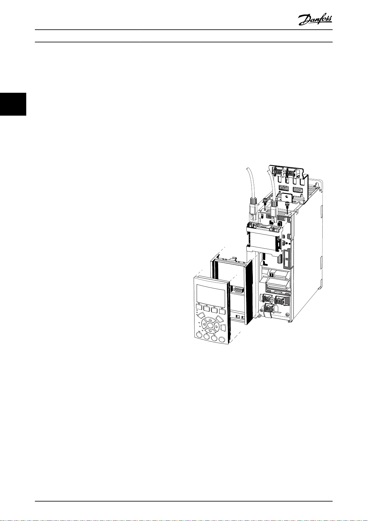
Installation Installation Guide
1 LCP
2 LCP cradle
3 Fieldbus option
3 3
Illustration 3.6 Exploded View
Illustration 3.8 Option Mounted with the Ethernet Port Facing
Downward (A4–A5, B, C, D, E, F Enclosures)
Signal M12 PIN # RJ45
RX + 1 1
TX + 2 3
RX - 3 2
TX - 4 4
Illustration 3.9 Ethernet Connectors
Illustration 3.7 Option Mounted with the Ethernet Port Facing
Upward (A1–A3 Enclosures)
MG92K102 Danfoss A/S © 05/2016 All rights reserved. 9
130BT797.11
Installation
VLT® BACnet/IP MCA 125
3.7 Electrical Installation
3.7.1 Cabling Requirements
Select cables suitable for Ethernet data
•
transmission. Normally, CAT5e and CAT6 cables
33
are recommended for industrial applications.
Both types are available as unshielded twisted
•
pair and shielded twisted pair. Shielded cables are
recommended for use in industrial environments
and with frequency converters.
A maximum cable length of 100 m (328 ft) is
•
allowed between the switches.
Use optical
•
and providing galvanic isolation.
bers for gapping longer distances
3.7.2 Wiring Procedures
Wiring procedure for enclosure types A1–A3
1. Mount the pre-congured cable wires with the
connectors on the eldbus option. For A1 and A2
enclosures, mount the supplied strain relief on
top of the frequency converter with 2 screws, as
shown in Illustration 3.10. For cable specications,
refer to chapter 3.7.1 Cabling Requirements.
2. Position the cable between the spring loaded
metal clamps to establish mechanical xation and
electrical contact between the cable and ground.
10 Danfoss A/S © 05/2016 All rights reserved. MG92K102
Illustration 3.10 Wiring for Enclosure Types A1–A3

130BD972.10
130BC527.10
Installation Installation Guide
Wiring procedure for enclosure types A4–A5, B1–B4, and
C1–C4
1. Push the cable through the cable glands.
2. Mount the pre-congured cable wires with the
connectors on the eldbus option. For cable
specications, refer to chapter 3.7.1 Cabling
Requirements.
3. Fix the cable to the metal base plate using the
springs, see Illustration 3.11.
4. Tighten the cable glands securely.
Wiring procedure for enclosure types D, E, and F
1. Mount the pre-congured cable wires with the
connectors on the eldbus option. For cable
specications, refer to chapter 3.7.1 Cabling
Requirements.
2. Fix the cable to the metal base plate using the
springs, see Illustration 3.12.
3. Tie down the cable and route it with other
control wires inside the unit, see Illustration 3.12.
3 3
Illustration 3.12 Wiring for Enclosure Types D, E, and F
Illustration 3.11 Wiring for Enclosure Types A4–A5, B1–B4, and
C1–C4
NOTICE
Do not strip the Ethernet cable. Do not ground it via the
strain relief plate. Ground the shielded Ethernet cables
through the RJ45 connector on the BACnet/IP interface.
3.8 Reassembling the Cover
1. Mount the new front cover and the LCP.
2. Attach the sticker with the correct product name
to the front cover.
Applying Power
3.9
Follow the instructions in the frequency converter
Operating Instructions to commission the frequency
converter. The frequency converter automatically detects
the BACnet/IP interface. A new parameter group (Group
8-7) appears.
MG92K102 Danfoss A/S © 05/2016 All rights reserved. 11

Installation
VLT® BACnet/IP MCA 125
3.10 Checking Network Cabling
NOTICE
After installing the BACnet/IP interface, be aware of the
following parameter settings:
Parameter 8-01 Control Site: [2] Control word only
33
•
or [0] Digital and control word
Parameter 8-02 Control Word Source: [3] Option
•
A.
Parameter 8-03 Control Timeout Time.
•
Parameter 8-70 BACnet Device Instance.
•
Parameter 12-71 BACnet Datalink.
•
If BACnet/IP is used the following parameters must be
set correctly:
Parameter 12-00 IP Address Assignment.
•
Parameter 12-01 IP Address (if parameter 12-00 IP
•
Address Assignment is set to [0] MANUAL).
Parameter 12-02 Subnet Mask (if
•
parameter 12-00 IP Address Assignment is set to
[0] MANUAL).
12 Danfoss A/S © 05/2016 All rights reserved. MG92K102

MS LED
NS LED’s
MCA 125
BACnet/IP
SW. ver. X.YY (TM: X:YY)
MS
NS2
NS1
MAC: 00:1B:08:XX:XX:XX
Option A
130B1586
Device Instance
8 7 6 5 4 3 2 1
MAC
Address
Ethernet Port 1
Ethernet Port 1
Ethernet Port 2
Ethernet Port 2
130BE803.10
Troubleshooting Installation Guide
4 Troubleshooting
4.1 Warnings and Alarms
NOTICE
Refer to the relevant frequency converter Operating
Instructions for an overview of warning and alarm types,
and for the full list of warnings and alarms.
Alarm word and warning word are shown in the display in
Hex format. When there is more than 1 warning or alarm,
the sum of all warnings or alarms is shown. Warning word
and alarm word are shown in parameter 16-90 Alarm Word
to parameter 16-95 Ext. Status Word 2.
4 4
4.2 Troubleshooting
Illustration 4.1 Overview of BACnet/IP Interface
4.2.1 LED Status
The BACnet/IP interface has 3 bicolored LEDs that allow
fast and detailed diagnosis. Each LED is linked to its unique
part of the BACnet/IP interface, see Table 4.1.
LED label Description
MS Module status. Reects the activity on the
BACnet/IP stack.
NS1 Network status 1. Reects the activity on
Ethernet port 1.
NS2 Network status 2. Reects the activity on
Ethernet port 2.
Table 4.1 LED Label
State LED Description
Power up Red/
green:
Green: Flashing green No IP address is congured.
Green: Solid green The link is OK and the IP address is congured.
Red: Flashing red Fault:
Running
Red:
Solid red/green The device is powering up.
IP address conict
•
Device ID error
•
Solid red Alarm
Table 4.2 MS: Module Status
MG92K102 Danfoss A/S © 05/2016 All rights reserved. 13

Troubleshooting
State LED Description
Power up Red/
green:
Running Green: Flashing green No IP address is congured.
Green: Solid green The link is active and the IP address is congured.
Red: Solid red The IP address assigned to the device is already in
O
VLT® BACnet/IP MCA 125
Solid red/green The device is powering up (after MS LED).
O
use.
There is no link or the link has been removed after
valid IP address has been entered.
44
Table 4.3 NS1+NS2: Network Status (1 per Port)
4.2.2 No Communication with the
Frequency Converter
Check: Link status
The status of the Ethernet link can be directly identied
using the LEDs, when no BACnet connection is established.
Use parameter 12-10 Link Status to verify presence of the
link.
Use parameter 12-11 Link Duration to verify that the link is
steadily present.
The parameter shows the duration of the present link, and
is preset to 00:00:00:00 when the link is broken.
Check: Cabling
In rare cases of cabling misconguration, the option may
show the presence of a link but no communication is
running. Exchange the cable if in doubt.
Check: IP address
Verify that the option has a valid IP address (refer to
parameter 12-01 IP Address). When the option has identied
a duplicate IP Address, NS LEDs are steady red. When the
option is set up for BOOTP or DHCP, verify that a BOOTP or
DHCP Server is connected in parameter 12-04 DHCP Server.
If no server is connected, the parameter shows:
000.000.000.000.
14 Danfoss A/S © 05/2016 All rights reserved. MG92K102

Index Installation Guide
Index
A
Abbreviations........................................................................................... 3
Additional resources.............................................................................. 2
Alarms....................................................................................................... 13
Applying power.................................................................................... 11
Approvals................................................................................................... 2
C
Cable routing............................................................................................ 6
Cabling..................................................................................................... 14
Cabling requirements......................................................................... 10
Certications............................................................................................. 2
Conventions.............................................................................................. 3
N
Network cabling.................................................................................... 12
Q
Qualied personnel................................................................................ 4
R
Redundancy manager switch............................................................. 8
Ring/redundant topology.................................................................... 8
S
Safety........................................................................................................... 5
Shielded cable................................................................................... 6, 10
Star topology............................................................................................ 7
Symbols...................................................................................................... 3
D
Discharge time......................................................................................... 4
E
Electrical interference............................................................................ 6
EMC interference..................................................................................... 6
EMC-compliant installation................................................................. 6
Ethernet................................................................................................... 14
Exploded view.......................................................................................... 8
G
Grounding................................................................................................. 6
H
High voltage............................................................................................. 4
I
Installation
EMC-compliant.................................................................................... 6
Intended use............................................................................................. 2
Items supplied.......................................................................................... 2
T
Topology.................................................................................................... 7
Topology
Recommended design rules........................................................... 8
U
Unintended start..................................................................................... 4
W
Warnings.................................................................................................. 13
Wiring procedure.................................................................................. 10
L
Leakage current....................................................................................... 5
LED............................................................................................................... 3
Line topology........................................................................................... 7
Load sharing............................................................................................. 4
M
Motor wiring............................................................................................. 6
Mounting................................................................................................... 8
MG92K102 Danfoss A/S © 05/2016 All rights reserved. 15

Danfoss can accept no responsibility for possible errors in catalogues, brochures and other printed material. Danfoss reserves the right to alter its products without notice. This also applies to
products already on order provided that such alterations can be made without subsequential changes being necessary in specications already agreed. All trademarks in this material are property
of the respective companies. Danfoss and the Danfoss logotype are trademarks of Danfoss A/S. All rights reserved.
Danfoss A/S
Ulsnaes 1
DK-6300 Graasten
vlt-drives.danfoss.com
130R0672 MG92K102 05/2016
*MG92K102*
 Loading...