

Page 1
MAKING MODERN LIVING POSSIBLE
Operating Instructions
MCA 123 POWERLINK
vlt-drives.danfoss.com
Page 2

Page 3

Safety Operating Instructions
Safety
This publication contains information proprietary to
Danfoss. By accepting and using this manual, the user
agrees that the information contained herein is used solely
for operating equipment from Danfoss or equipment from
other vendors if such equipment is intended for communication with Danfoss equipment over a serial
communication link. This publication is protected under
the Copyright laws of Denmark and most other countries.
Danfoss does not guarantee that a software program
produced according to the guidelines provided in this
manual functions properly in every physical, hardware, or
software environment.
Although Danfoss has tested and reviewed the documentation within this manual, Danfoss gives no warranty or
representation, either expressed or implied, with respect to
this documentation. This includes its quality, performance,
or rness for a particular purpose.
In no event shall Danfoss be liable for direct, indirect,
special, incidental, or consequential damages arising out of
the use, or the inability to use information contained in
this manual, even if advised of the possibility of such
damages. In particular, Danfoss is not responsible for any
costs including, but not limited to those incurred as a
result of lost prots or revenue, loss or damage of
equipment, loss of computer programs, loss of data, the
costs to substitute these, or any claims by third parties.
1. The frequency converter must be disconnected
from mains before carrying out repair work.
Check that the mains supply has been disconnected and that the necessary time has passed
before removing motor and mains plugs.
2. The o-command on the serial bus does not
disconnect the equipment from mains and should
not be used as a safety switch.
3. Correct protective earthing or grounding of the
equipment must be established. The user must
be protected against supply voltage, and the
motor must be protected against overload in
accordance with applicable national and local
regulations.
4. The earth leakage currents are higher than 3.5
mA.
5. Do not remove the plugs for the motor and
mains supply while the frequency converter is
connected to mains. Check that the mains supply
has been disconnected and that the necessary
time has passed before removing motor and
mains plugs.
Danfoss reserves the right to revise this publication at any
time and to change its contents without prior notice or
any obligation to notify previous users of such revisions or
changes.
It has been assumed that all devices are sitting behind a
rewall that does packet ltering and the environment has
implemented restrictions on the software that can run
inside the rewall. All nodes are assumed to be "trusted"
nodes.
WARNING
HIGH VOLTAGE
The voltage of the frequency converter is dangerous
whenever connected to mains. Incorrect installation of
the motor, frequency converter, or eldbus may damage
the equipment, cause serious personal injury, or death.
Consequently, the instructions in this manual, as well as
national and local rules and safety regulations, must be
complied with.
MG92C202 Danfoss A/S © Rev. 2013-02-11 All rights reserved.
Page 4

Safety MCA 123 POWERLINK
1. The motor can be brought to a stop with bus
commands while the frequency converter is
connected to mains. These stop functions do NOT
provide protection against unintended starts.
2. While parameters are being changed, there is a
risk that motor starts.
3. Electronic faults in the frequency converter and
cease of
temporary overload
•
faults in supply mains, or
•
fault in the motor connection
•
can cause an unintended start.
WARNING
ELECTRICAL HAZARD
Touching the electrical parts may be fatal - even after
the equipment has been disconnected from mains.
Danfoss A/S © Rev. 2013-02-11 All rights reserved. MG92C202
Page 5

Contents Operating Instructions
Contents
1 Introduction
1.1 General Information
1.1.1 About this Manual 3
1.1.2 Assumptions 3
1.1.3 Hardware 3
1.1.4 Background Knowledge 3
1.1.5 Available Literature 3
1.1.6 Abbreviations 4
2 How to Install
2.1 Installation
2.1.1 How to Install Option in Frequency Converter 5
2.1.2 Network 5
2.1.3 POWERLINK Cables 6
2.1.4 LED Behaviour 6
2.1.5 Topology 7
2.1.6 EMC Precautions 8
3
3
5
5
3 How to Congure
3.1 Congure the Parameters
3.1.1 IP Settings 10
3.1.2 Ethernet Link Parameters 10
3.2 Congure the Frequency Converter
3.2.1 VLT Parameters 10
3.3 Congure the POWERLINK Network
4 Congure the Master
4.1 Importing the XDD File
4.2 Setting Up the Master
5 How to Control the Frequency Converter
5.1 PDO Communication
5.2 Process Data
5.2.1 Process Control Data 15
5.2.2 Process Status Data 15
5.2.3 Reference Handling 16
10
10
10
10
12
12
12
15
15
15
5.2.5 Inuence of the Digital Input Terminals upon FC Control Mode 17
5.3 Control Prole
5.4 DS 402 Control Prole
5.4.1 Control Word According to DSP 402 Prole
(Parameter 8-10=DSP 402 prole) 17
MG92C202 Danfoss A/S © Rev. 2013-02-11 All rights reserved. 1
17
17
Page 6

Contents MCA 123 POWERLINK
5.4.2 Status Word According to DS 402 Prole 18
5.4.3 DSP 402 State Transitions 21
5.5 Danfoss FC Control Prole
6 Communication Prole Area
6.1 Description - Communication Prole Area
6.2 1000-1FFF Communication Object Area
6.3 2000-5FFF Danfoss Specic Object Area
6.4 6000-Device prole Object Area
7 Parameters
7.1 Parameter Group 8-** Communication and Option
7.2 Parameter Group 12-** Ethernet
7.3 POWERLINK - Specic Parameter List
8 Application Examples
8.1 Example: Process Data with PDO 23
8.2 Example: Simple Control Word, Reference, Status Word and Main Actual Value
9 Troubleshooting
9.1 LED Status
21
25
25
25
31
31
34
34
38
41
44
44
46
48
48
9.2 Communication Problems
9.2.1 No Communication with the Frequency Converter 49
9.2.2 Endless Power-down - Power-up Cycle 52
9.3 Warnings and Alarms
9.3.1 Alarm and Warning Words 52
Index
49
52
55
2 Danfoss A/S © Rev. 2013-02-11 All rights reserved. MG92C202
Page 7

Introduction
Operating Instructions
1 Introduction
1.1 General Information
1.1.1 About this Manual
Chapters
chapter 1 Introduction
chapter 2 How to Install
chapter 3 How to
contain essential information for quick installation and setup.
For more detailed information, including the full range of
set-up options and diagnosis tools, refer to the chapters:
chapter 4
chapter 5 How to Control the Frequency Converter
chapter 7 Parameters
chapter 8 Application Examples
chapter 9 Troubleshooting
Terminology
In this manual the term Ethernet is used to describe the
physical layer of the network and does not relate to the
application protocol.
Assumptions
1.1.2
These Operating Instructions are under the conditions that
the Danfoss POWERLINK option is used with a Danfoss
VLT® AutomationDrive FC 301/FC 302 or FCD 302
frequency converter. The installed controller must support
the interfaces described in this manual. Strictly observe all
the requirements stipulated in the controller and the
frequency converter, along with all limitations herein.
Hardware
1.1.3
This manual relates to the POWERLINK option MCA 123,
ordering number 130B5546 (uncoated) and 130B5646
(conformal coated).
1.1.4
Background Knowledge
The Danfoss POWERLINK option card is designed to
communicate with any system complying with the
POWERLINK standard. Familiarity with this technology is
assumed. Issues regarding hardware or software produced
by other manufacturers, including commissioning tools, are
Congure
Congure the Master
beyond the scope of this manual, and not the responsibility of Danfoss.
For information regarding commissioning tools, or
communication to a non-Danfoss node, consult the
appropriate manuals.
1.1.5 Available Literature
-
The VLT® AutomationDrive Operating Instructions
provide the necessary information for getting the
frequency converter up and running.
-
-
-
-
-
-
-
-
-
-
-
-
Danfoss technical literature is also available online at
www.danfoss.com/BusinessAreas/DrivesSolutions/
®
The VLT
technical information about the frequency
converter design and applications including
encoder, resolver, and relay options.
The VLT® AutomationDrive Probus Operating
Instructions provide the information required for
controlling, monitoring, and programming the
frequency converter via a Probus eldbus.
The VLT
Instructions provide the information required for
controlling, monitoring, and programming the
frequency converter via a DeviceNet eldbus.
The MCT 10 Set-up Software Operating Instructions
provide information for installation and use of the
software on a PC.
The VLT
provides information for installing the IP21/Type 1
option.
The VLT
Instruction provides information for installing the
24 V DC Back-up option.
The VLT
Instructions.
The VLT
Instructions.
The MCA 121 Ethernet/IP Operating Instructions.
The MCA 120 PROFINET Operating Instructions.
The MCA 124 EtherCAT Operating Instructions.
The MCA 122 Modbus TCP Operating Instructions.
AutomationDrive Design Guide entails all
®
AutomationDrive DeviceNet Operating
®
AutomationDrive IP21/Type 1 Instruction
®
AutomationDrive 24 V DC Back-up
®
AutomationDrive CANOpen Operating
®
AutomationDrive Modbus TCP Operating
1
1
MG92C202 Danfoss A/S © Rev. 2013-02-11 All rights reserved. 3
Page 8

Introduction MCA 123 POWERLINK
1.1.6 Abbreviations
1
Abbreviation
API Actual Packet Interval
ASnd AsynchronousSend
CC Control card
CTW Control word
DCP Discovery and Conguration Protocol
DHCP Dynamic Host Conguration Protocol Conguration
EMC Electromagnetic Compatibility
I/O Input/Output
IP Internet Protocol
PDO Process Data Object
LCP Local Control Panel
LED Light Emitting Diode
LSB Least Signicant Bit
MAV Main Actual Value (actual output)
MN Managing Node
MSB Most Signicant Bit
MRV Main Reference Value
N/A Not applicable
PC Personal Computer
PCD Process Control Data
PLC Programmable Logic Controller
PNU Parameter Number
REF Reference (=MRV)
SDO Service Data Object
SoC Start Of Cycle Frame
SoA Start Of Asynchronous
STW Status Word
Denition
Table 1.1 Overview of Abbreviations
4 Danfoss A/S © Rev. 2013-02-11 All rights reserved. MG92C202
Page 9
EtherNet Port1
EtherNet Port2
MCA 121 Option A
EtherNet/IP 130B1119
MS
MS1 MAC-00-1B-08-00-00-22
MS2
SW.ver.
130BT797.10
How to Install
2 How to Install
2.1 Installation
Operating Instructions
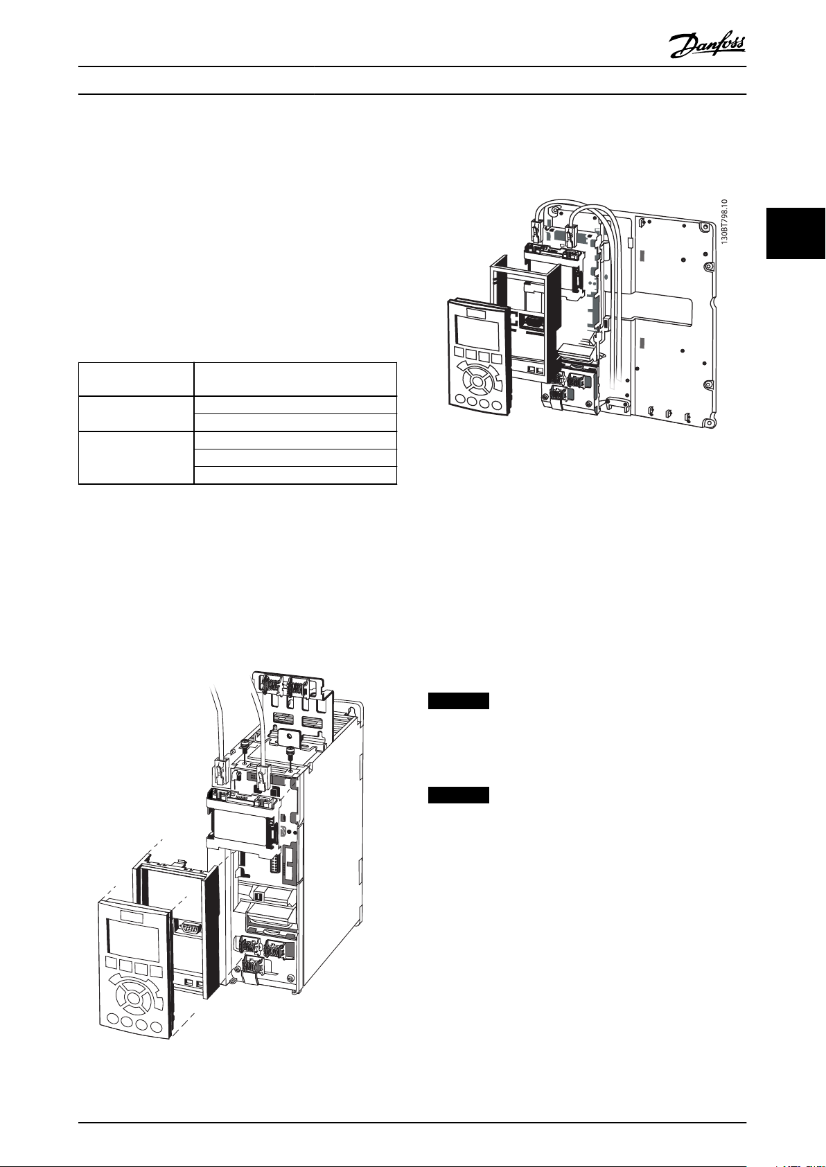
2.1.1 How to Install Option in Frequency
Converter
Before installing the option, make sure that the installed
rmware revision supports the POWERLINK option.
Following minimum versions of the frequency converter
rmware are required:
POWERLINK option
rmware version
1.01
1.12 FC 301 6.81
Table 2.1 Minimum Firmware Versions
Items required for installing the eldbus option in the
frequency converter
Fieldbus option
•
Fieldbus option adaptor frame for the FC Series.
•
This frame is deeper than the standard frame to
allow space for the eldbus option beneath.
Strain relief (only for A1 and A2 enclosures)
•
Frequency converter minimum
rmware version
FC 301 6.72
FC 302 6.72
FC 302 6.81
FCD 302 6.81
Illustration 2.2 Strain Relief for A1 and A2 Enclosures
Instructions
1. Remove LCP panel from the FC Series.
2. Remove the frame located beneath and discard it.
3. Push the option into place. The Ethernet
connectors must be facing upwards.
4. Remove knock-out on the
eldbus option adaptor
frame.
5. Push the eldbus option adaptor frame for the FC
Series into place.
6. Replace the LCP and attach cable.
2 2
Illustration 2.1 Fieldbus Option Adaption Frame
NOTICE
Do not strip and earth the Ethernet cable via the strain
relief-plate! The earthing of screened Ethernet cable is
done through the RJ-45 connector on the option.
NOTICE
After installing the MCA 123 POWERLINK option, set
parameter 8-01 Control Site to: [2] Control word only or [0]
Digital and ctrl. word.
parameter 8-02 Control Word Source to: [3] Option A
2.1.2 Network
It is important that the media selected for Ethernet data
transmission meets the required properties. Usually CAT 5e
and six cables are recommended for industrial applications.
Both types are available as unscreened twisted pair and
screened twisted pair. Generally, screened cables are
recommended for use in industrial environments and with
frequency converters.
A maximum cable-length of 100 m is allowed between
network devices.
MG92C202 Danfoss A/S © Rev. 2013-02-11 All rights reserved. 5
Page 10
MCA123
POWERLINK
SW. ver. TM. ver.
S/E LED
L/C LED P1
L/C LED P2
Port 1 Port 2
Option A
130B1489
MAC 00-1B-08-00-00-00
Address
8 7 6 5 4 3 2 1
ON
OFF
130BD146.11
1
2
3
4
5
6
A
B
A
B
How to Install MCA 123 POWERLINK
2.1.3 POWERLINK Cables
Cable type Specication
S/E LED
Illustration 2.4 S/E LED Status - Power OFF or State
Ethernet standard Standard Ethernet (in accordance with IEEE
802.3), 100Base-TX (Fast Ethernet)
Cable Type S/FTP (screened foiled twisted pair, ISO (IEC
22
Damping 23.2 dB (at 100 MHz and 100 m each)
Crosstalk
11801 or EN 50173), CAT 5e
24 dB (at 100 MHz and 100 m each)
Illustration 2.5 S/E LED Status - Green (A)/Red (B) Flash
damping
Return loss 10 dB (100 m each)
Surge impedance
Table 2.2 Specication of POWERLINK Cables
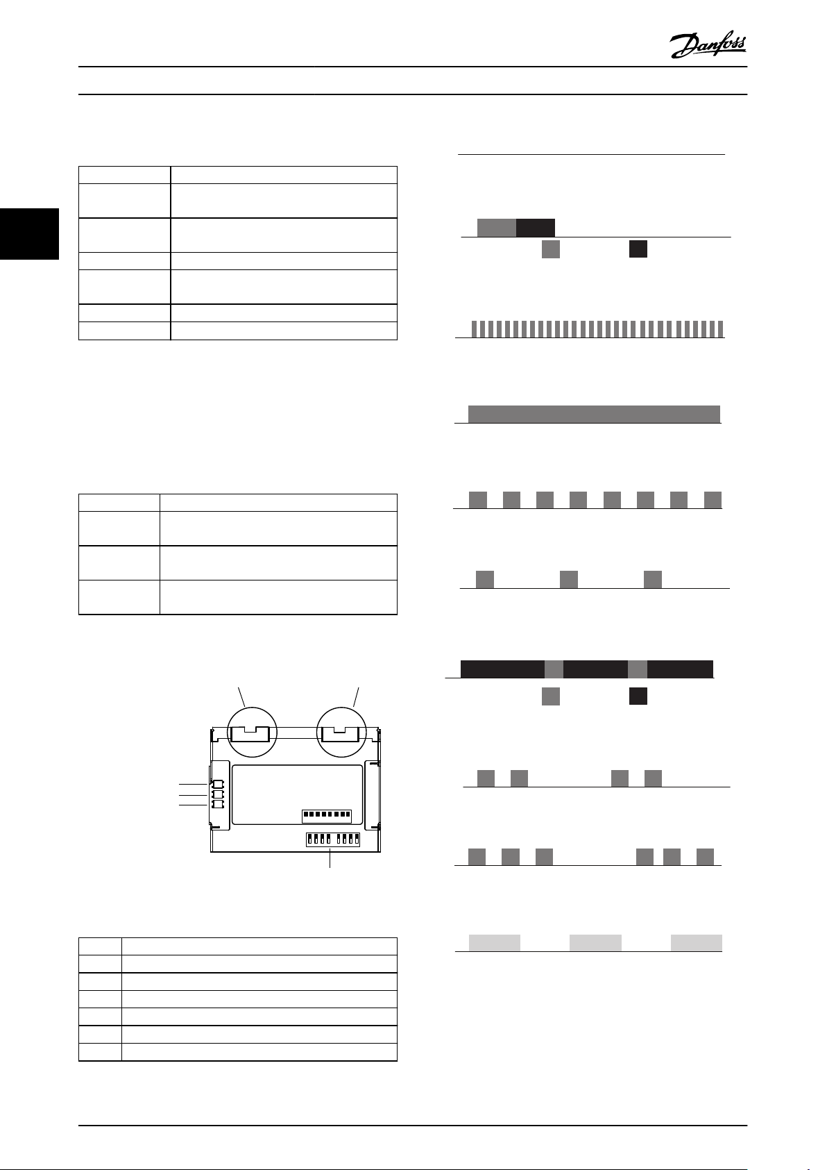
LED Behaviour
2.1.4
The option has 3 bicolored LEDs that allow a fast and
detailed diagnosis. The three LEDs are each linked to its
100 Ω
Illustration 2.6 S/E LED Status - Flickering Green
Illustration 2.7 S/E LED Status - Solid Green
unique part of the POWERLINK option:
LED label Description
Status/Error Module Status, reects the activity on the
POWERLINK slave.
Link/Collision
Port 1
Link/Collision
Port 2
Link/Collision Port 1, reects the activity on the
POWERLINK port 1.
Link/Collision Port 2, reects the activity on the
POWERLINK port 2.
Illustration 2.8 S/E LED Status - Blinking Red
Illustration 2.9 S/E LED Status - Single Green Flash
Table 2.3 LEDs
Illustration 2.3 Overview of the Option
Item # Description
1 POWERLINK port 1
2 POWERLINK port 2
3 Status/error
4 Link/collision port 1
5 Link/collision port 2
6 Node ID dip switches
Table 2.4 Legend to Illustration 2.3
Illustration 2.10 S/E LED Status - Red (B)/Green (A) Flash
Illustration 2.11 S/E LED Status - Double Green Flash
Illustration 2.12 S/E LED Status - Tripple Green Flash
Illustration 2.13 S/E LED Status - Yellow Flash
6 Danfoss A/S © Rev. 2013-02-11 All rights reserved. MG92C202
Page 11
A
B
A
B
How to Install Operating Instructions
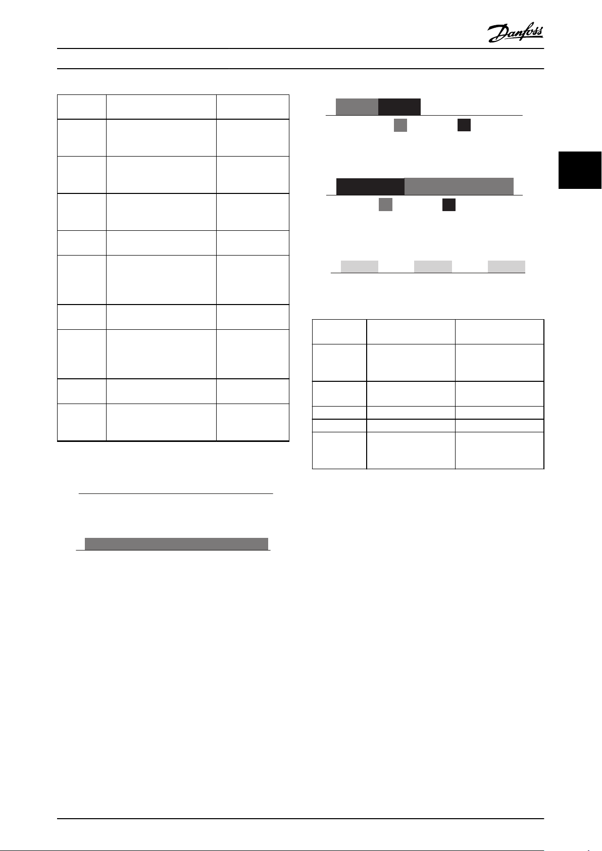
LED ash
pattern
Power OFF
or State
Flickering
Green
Solid green POWERLINK
Blinking
greed
Single green
ash
Red/green
ash
Double
green ash
Tripple
green ash
Yellow ash Wink command Node Identication
Table 2.5 S/E LED Pattern
Powerlink option state Description
NMT_GS,
NMT_GS_INITIALISATION
NMT_CS_NOT_ACTIVE,
Basic Ethernet mode POWERLINK
NMT_CS_Stopped PLC has stopped
NMT_CS_PRE_OPERATIONAL_1 POWERLINK
NMT_CS_PRE_OPERATIONAL_1 Communication to
NMT_CS_PRE_OPERATIONAL_2 POWERLINK
NMT_CS_READY_TO_OPERATE POWERLINK
No power supplied
to drive or
Initialising
interface is in basic
Ethernet mode
interface is on
operational state
the Network
interface is in Preoperation mode
state 1
PLC lost
interface is in Preoperation mode
state 2
interface is
activated from
MCT10
Illustration 2.16 L/C LED Status - Power-up Green (A)/Red (B)
Illustration 2.17 L/C LED Status - Collision Red (B)/Green (A)
Illustration 2.18 L/C LED Status - Yellow Flash
LED ash
pattern
Power OFF or
no link
Link NMT_GS_INITIALISATION Only shown once at
Power up Various states Link established
Collision
Yellow ash Wink command Node Identication
Powerlink option state Description
NMT_GS,
NMT_GS_INITIALISATION
NMT_CS_NOT_ACTIVE
No power supplied to
drive or Initialising
power up
activated from MCT 10
Set-up Software
2 2
L/C LED
Illustration 2.14 L/C LED Status - Power OFF or No Link
Illustration 2.15 L/C LED Status - Link
Topology
2.1.5
Table 2.6 L/C LED Pattern
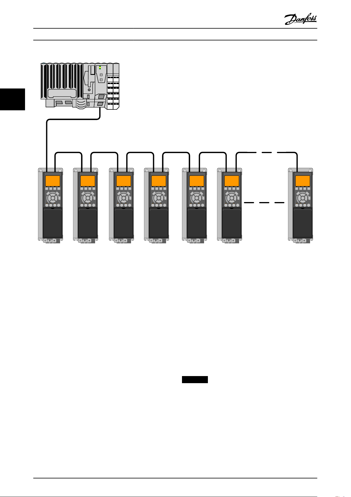
The POWERLINK module features a built-in POWERLINK controlled node and a two-port hub. This module enables the
possibility for connecting several POWERLINK options in a line topology. If more than eight frequency converters are
connected in line, it requires special attention towards the timing in the network.
It is important in a POWERLINK system, that the connection is done correctly.
MG92C202 Danfoss A/S © Rev. 2013-02-11 All rights reserved. 7
Page 12
130BD147.10
How to Install MCA 123 POWERLINK
22
Illustration 2.19 Line Topology
Take care that following design rules are followed
1. Do not connect any non-POWERLINK device (e.g.
a PC) to any free port as to avoid malfunction of
the complete POWERLINK network.
2. In a line topology, power all frequency converters
either by mains or by a 24 V DC option card, for
the built-in POWERLINK slave controller to work.
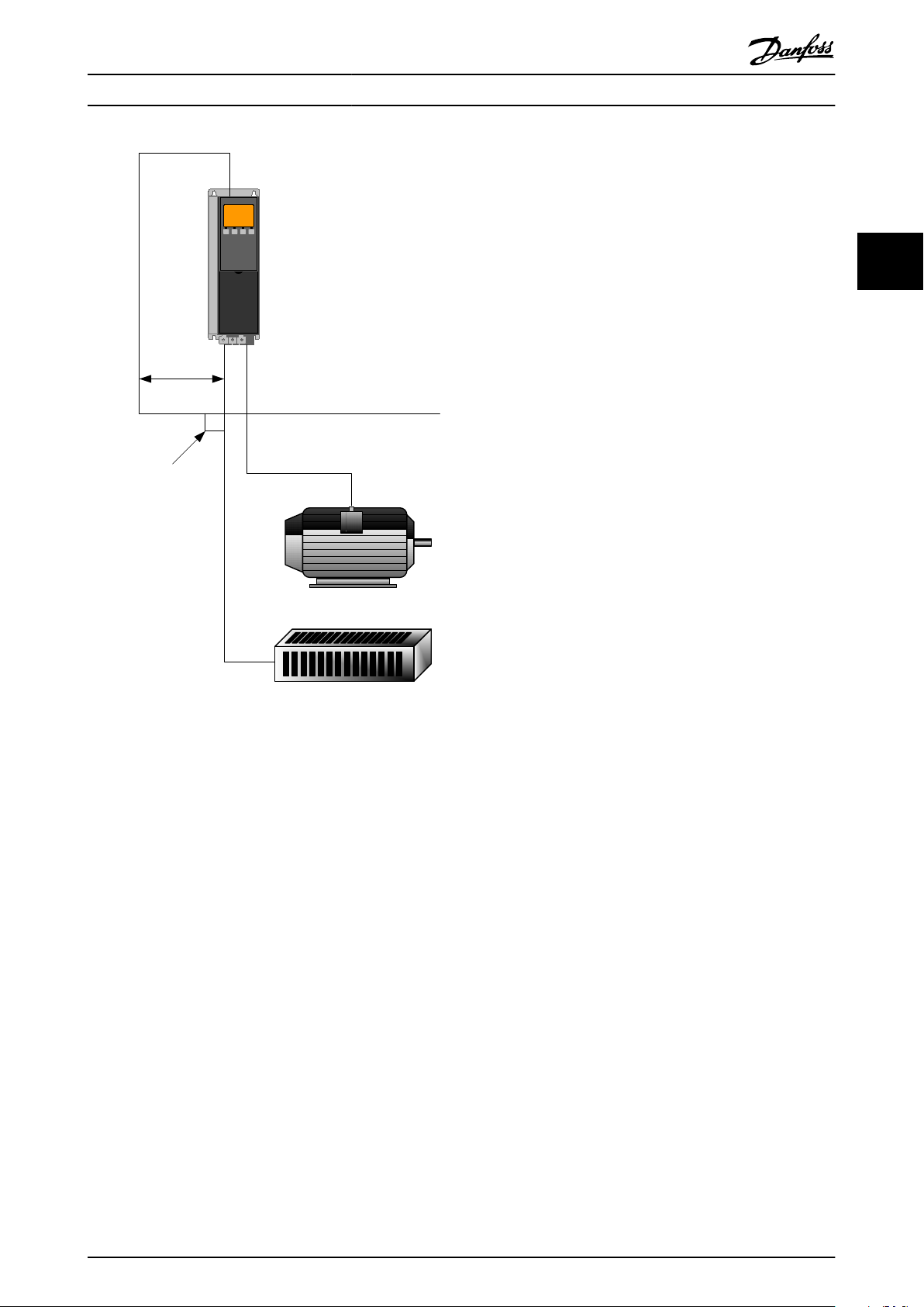
3. To achieve interference-free operation of the
Ethernet, observe the following EMC precautions.
The correct handling of the motor cable screen is
vital for the overall performance of the system. If
the rules are not followed, it leads to loss of the
control and malfunction of the system. The
Ethernet communication cable must be kept
away from motor and brake resistor cables to
avoid coupling of high frequency noise between
the cables. Normally, a minimum distance of 200
mm (8 inches) is sucient, but maintaining the
greatest possible distance between the cables is
recommended. Especially where cables run in
parallel, over long distances, or if frequency
converters with a bigger power size are installed.
More information can be found in the norm IEC
61000-5-2:1997.
4. When crossing of cables is unavoidable, the
Ethernet cable must cross motor and brake
resistor cables at an angle of 90°.
5. Always observe relevant national and local
regulations, for example regarding protective
earth connection.
2.1.6 EMC Precautions
To achieve interference-free operation of the Ethernet,
observe the following EMC precautions. Additional EMC
information is available in the VLT® AutomationDrive Design
Guide.
NOTICE
The correct handling of the motor cable screen is vital
for the overall performance of the system. If the rules are
not followed, it can lead to loss of the control and
malfunction of the system.
8 Danfoss A/S © Rev. 2013-02-11 All rights reserved. MG92C202
Page 13
min. 200 mm
90 ° crossing
Ethernet Cable
130BA908.11
How to Install Operating Instructions
2 2
Illustration 2.20 Correct Crossing of Ethernet Cable
MG92C202 Danfoss A/S © Rev. 2013-02-11 All rights reserved. 9
Page 14

How to Congure MCA 123 POWERLINK
3 How to Congure
3.1 Congure the Parameters
3.1.1 IP Settings
All IP-related parameters are located in parameter group
33
12-0* IP Settings: The parameters are all set to POWERLINK
standard values, so no setting is needed. In POWERLINK,
the parameter 12-00 IP Address Assignment is xed to the
option "From node ID". The IP address follows the setting
in parameter 12-60 Node ID, so that the IP address is
192.168.100.xxx, where xxx is the node ID. For
parameter 12-02 Subnet Mask, the IP addres is
255.255.255.0 and cannot be changed.
The POWERLINK option oers two ways of node ID
assignment via parameter or DIP switch.
Ethernet Link Parameters
3.1.2
Parameter group 12-1* Ethernet Link Parameters holds
Ethernet Link information:
Parameter 12-10 Link Status
Parameter 12-11 Link Duration
Parameter 12-12 Auto Negotiation
Parameter 12-13 Link Speed
Parameter 12-14 Link Duplex
Each port has unique Ethernet link parameters.
Parameter 12-10 Link Status displays Link or No Link
according to the status of the present port.
Parameter 12-11 Link Duration displays the duration of the
link on the present port. If the link is broken, the counter
is reset.
Parameter 12-12 Auto Negotiation is a feature that enables
two connected Ethernet devices to select common
transmission parameters, such as speed and duplex mode.
In POWERLINK, this feature is
changed.
xed to OFF and cannot be
xed to
In POWERLINK, the Link Duplex is xed to Half Duplex, and
cannot be changed.
3.2 Congure the Frequency Converter
3.2.1 VLT Parameters
Pay particular attention to the following parameters when
conguring the frequency converter with a eldbus
interface.
Parameter 0-40 [Hand on] Key on LCP. If the [Hand
•
on] key on the frequency converter is activated,
control of the frequency converter via the
eldbus interface is disabled.
After an initial power-up, the frequency converter
•
automatically detects whether a eldbus option is
installed in slot A. It then sets
parameter 8-02 Control Word Source to [Option A].
Adding, changing, or removing an option from an
already commissioned frequency converter does
not change parameter 8-02 Control Word Source.
However, it causes a trip mode, and the
frequency converter displays an error.
Parameter 8-10 Control Word
•
between the Danfoss FC
prole. The change of parameter 8-10 Control
Word Prole is active at the next power-up.
Parameter 8-50 Coasting Select to
•
parameter 8-56 Preset Reference Select. Selection of
how to gate
digital input command of the control card.
eldbus control commands with
Prole. Select
Prole and the DS 402
NOTICE
When parameter 8-01 Control Site is set to [2] Control
word only, Bus-control overrules the settings in
parameter 8-50 Coasting Select to parameter 8-56 Preset
Reference Select.
Parameter 8-03 Control Word Timeout Time to
•
parameter 8-05 End-of-Timeout Function. The
reaction in the event of a bus time-out is set via
these parameters.
3.3
Congure the POWERLINK Network
Parameter 12-13 Link Speed - displays the link speed for
each port. If no link is present, “None” is displayed. In
POWERLINK, this feature is xed to 100 MBaud and cannot
be changed.
Parameter 12-14 Link Duplex - displays the duplex mode for
each port.
Using the hardware switches, it is possible to select an address range 0–239 (factory setting 1) according to
10 Danfoss A/S © Rev. 2013-02-11 All rights reserved. MG92C202
All POWERLINK stations that are connected to the same
bus network must have a unique node address. The node
address of the frequency converter can be selected via:
Hardware switches (from version 1.12)
•
parameter 12-60 Node ID
•
Setting the NODE Address using the Hardware Switches
Table 3.1:
Page 15

How to Congure Operating Instructions
Switch 8 7 6 5 4 3 2 1
Address value 128 +64 +32 +16 +8 +4 +2 +1
E.g. address 5 OFF OFF OFF OFF OFF ON OFF ON
E.g. address 35 OFF OFF ON OFF OFF OFF ON ON
E.g. address 82 OFF ON OFF ON OFF OFF ON OFF
E.g. address 157 ON OFF OFF ON ON ON OFF ON
Table 3.1
NOTICE
The switches are only read during power-up. Changes are active after the next power up, and can be read in
parameter 12-60 Node ID. Note the location and sequence of the hardware switches as illustrated in Illustration 2.3.
Setting the NODE Address via parameter 12-60 Node ID
Setting the address via parameter 12-60 Node ID, is only possible if the hardware switches are set to 0 or 255 (factory
setting). The address change becomes active at the next power-up. The node address has direct
in parameter 12-01 IP Address. If the hardware switch is set to an illegal number, the frequency converter immediately issues
Warning 34 in the display, and parameter 12-69 Ethernet PowerLink Status is set to 0 (zero).
inuence on the IP address
3 3
MG92C202 Danfoss A/S © Rev. 2013-02-11 All rights reserved. 11
Page 16
130BD136.10
130BD139.10
130BD137.10
130BD140.10
Congure the Master MCA 123 POWERLINK
4 Congure the Master
4.1 Importing the XDD File
To congure a POWERLINK Master, the conguration tool
needs an XDD le for each type of slave on the network.
The XDD le is a text le containing the necessary
communications set-up data for a slave. Download the
le for the FC Series frequency converters at
XDD
www.danfoss.com/BusinessAreas/DrivesSolutions/.
44
parameter 15-61 Option
SW Version
1.02 FC 301: 0x0200008D_FC301_01.xdd
1.12 FC 301: 0x0200008D_FC301_08.xdd
Table 4.1 POWERLINK SW Version XDD File
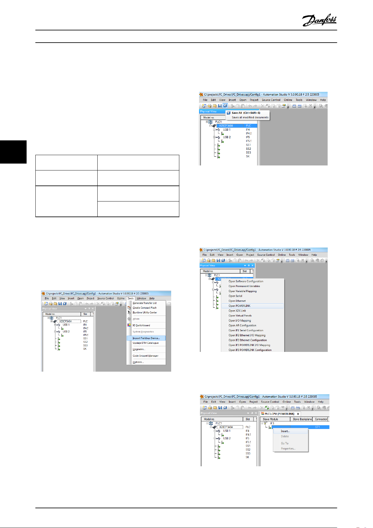
The following steps show how to add a device to the
Automation Studio Tool. For tools from other vendors,
consult their relevant manuals.
1. In the Automation Studio, select the menu [Tools]
and [Import Fieldbus Device].
File
FC 302: 0x0200008D_FC302_01.xdd
FC 302: 0x0200008D_FC302_08.xdd
FCD 302: FCD 302:
0x0200008D_FCD302_08.xdd
Illustration 4.2 Selecting the XDD File
4.2 Setting Up the Master
Select the POWERLINK I/O master to open the POWERLINK
interface in the Automation Studio Master.
1. Right click and select [Open POWERLINK].
Illustration 4.3 Open POWERLINK
Illustration 4.1 Automation Studio
2. Select the XDD le and the Automation studio,
imports it to its library. To save the new info,
select the [Save All] menu or the multiple oppy
disc icon.
12 Danfoss A/S © Rev. 2013-02-11 All rights reserved. MG92C202
2. Right click the network icon, and select [Insert].
Illustration 4.4 Physical View
Page 17
130BD145.11
130BD142.10
130BD141.10
130BD142.10
Congure
the Master Operating Instructions
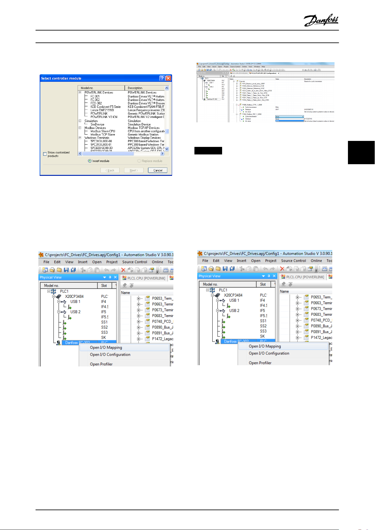
3. Select [Danfoss FC 302].
Illustration 4.7 Select Parameters
Illustration 4.5 Select Controller Module
Danfoss FC Series is inserted in the POWERLINK master
system.
Congure the I/O conguration, right click the
4.
Danfoss Icon and select [Open I/O Conguration].
NOTICE
Make sure that maximum ten channels are selected in
each direction; or the PLC enters into an endless restart
of the network.
6. The POWERLINK
the Danfoss FC Series frequency converter as its
slave and communicates with the four words. The
nal step is to map the I/Os to PLC variables,
which is done in the I/O mapping. Select the I/O
Mappings by right-clicking the [Danfoss FC 302]
icon and selecting [Open I/O Mapping].
conguration does now contain
4 4
Illustration 4.6 I/O Conguration
5. By default the POWERLINK option does not have
any process data assigned to its I/O mapping.
Assign the process data by selecting the channels
(FC Parameter) as read or write. Selecting the [+]
sign in front of the channel menu expands the
list and the parameters can be selected. In this
example following has been selected:
Object 2690 eldbus control word 1
•
Object 2692 eldbus reference 1
•
Object 2643 status word
•
Object 2645 main actual value
•
MG92C202 Danfoss A/S © Rev. 2013-02-11 All rights reserved. 13
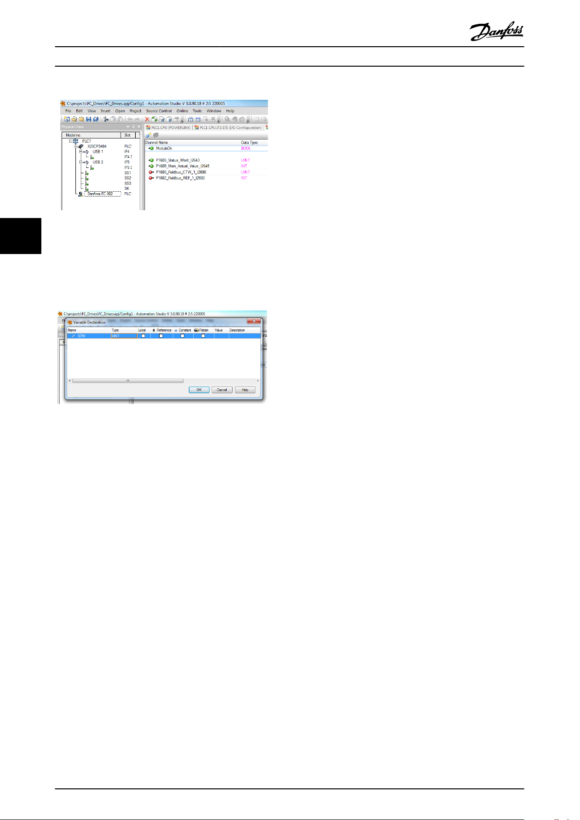
Illustration 4.8 Mapping the I/Os ot the PLC Variables
Now, the mapping can be done directly to previous
dened variables.
Page 18
130BD143.10
130BD144.10
Congure the Master MCA 123 POWERLINK
Illustration 4.9 Previous Dened Variables
44
Variables can also be directly declared, via selecting the
Channel Name for each signal and enter the attributes
directly.
Illustration 4.10 Variables Directly Declared
This inserts the Danfoss FC 302 into the B&R system, and
the frequency converter can now be controlled and
supervised via the POWERLINK.
14 Danfoss A/S © Rev. 2013-02-11 All rights reserved. MG92C202
Page 19

Receive PDOs (PLC
Drive)
Transmit PDOs (Drive PLC)
PCD 9
write
PDO 23
PCD 0
CTW
PCD 1
REF
PCD 9
read
PCD 0
STW
PCD 1
MAV
PDO 23
130BC177.10
How to Control the Frequenc...
Operating Instructions
5 How to Control the Frequency Converter
5.1 PDO Communication
The frequency converter uses the following proles:
Frequency converter proles
•
CANOpen DS 402 prole
•
For each of the two proles there is a set of SDO objects
that is only accessible if the prole is activated in
parameter 8-10 Control Word Prole. The change is active at
the next power-up. Congure the PDO communication,
where a subset of SDOs can be mapped into PDOs for
cyclic communication.
PDO communication is reserved for high-speed cyclic
access to parameters for control and status of the
frequency converter. The PLC sends out process control
data, and the frequency converter responds with a PDO
containing process status data. In the Danfoss POWERLINK
interface, both PDOs can be congured freely.
Select the signals for transmission from the master to the
frequency converter via the PLCs
PLC sets Parameter 12-21 Process Data
parameter 12-22EN-22 Process Data Cong Read and
parameter 12-23 Process Data Cong Write Size, which can
be used to control that the conguration has been sent
correctly from the PLC.
conguration tool. The
Cong Write,
5.2 Process Data
Use the process data part of the PDO for controlling and
monitoring the frequency converter via the POWERLINK.
5.2.1 Process Control Data
The example in Table 5.1 shows control and reference sent
from the PLC to the frequency converter, and status word
and Main Actual Value sent from the frequency converter
to the PLC.
Master to slave
0 1 2 ...... 9
PCD write
Table 5.1 Process Control Data (PCD)
CTW MRV PCD ...... PCD
PCD 0 contains a 16-bit control word where each bit
controls a specic function of the frequency converter, see
chapter 5.3 Control Prole. PCD 1 contains a 16-bit speed
setpoint in percentage format. See chapter 5.2.3 Reference
Handling.
The content of PCD 2 to PCD 9 is read only.
5 5
The POWERLINK option has only one PDO available: PDO
23. The PDO 23 is
exible in size and is adjustable to t all
needs (max. 10 PCDs). The selection is made in the master
conguration and is then automatically downloaded to the
frequency converter during the transition from Init to PreOp. No manual setting of PPO types in the frequency
converter is required.
Option [1] Standard telegram 1 is equivalent to PDO 23.
Illustration 5.1 Standard Telegram
Process Status Data
5.2.2
Process data sent from the frequency converter contain
information about the current state of the frequency
converter.
Slave to master
0 1 2 ...... 9
STW MAV PCD ...... PCD
PCD read
Table 5.2 Process Status Data
PCD 0 contains a 16-bit status word where each bit
contains information regarding a possible state of the
frequency converter.
PCD 1 contains per default the value of the current speed
of the frequency converter in percentage format (see
chapter 5.2.3 Reference Handling).
MG92C202 Danfoss A/S © Rev. 2013-02-11 All rights reserved. 15
Page 20

How to Control the Frequenc...
MCA 123 POWERLINK
5.2.3 Reference Handling
The reference handling in FC Series is an advanced
mechanism that sums up references from dierent sources.
For more information on reference handling, refer to the
VLT® AutomationDrive Design Guide.
Limit [Hz]
limit the actual frequency converter output.
parameter 4-19 Max Output Frequency limits the maximum
output and can also inuence the maximum speed of the
motor.
For reference and MAV formats, see Table 5.3.
55
Illustration 5.2 Reference Handling
Table 5.3 Reference and MAV Formats
The reference, or speed setpoint (MRV, sent via
POWERLINK), is always transmitted to the frequency
converter in percentage format as integers represented in
hexadecimal (0-4000 hex).
NOTICE
Negative numbers are formed as a complement of two.
and parameter 4-14 Motor Speed High Limit [Hz]
MRV/MAV Integer in hex Integer in decimal
100% 4000 16.384
75% 3000 12.288
50% 2000 8.192
25% 1000 4.096
0% 0 0
-25% F000 -4.096
-50% E000 -8.192
-75% D000 -12.288
-100% C000 -16.384
NOTICE
Depending on the setting of parameter 3-00 Reference
Range the reference and MAV are scaled accordingly:
The data type for MRV and MAV is 16-bit standardise
value, which can express a range from -200% to +200%
(8001 to 7FFF).
Illustration 5.3 Scaling of MAV and Reference
NOTICE
If parameter 3-00 Reference Range is set to [0] Min - Max,
a negative reference is handled as 0%.
The speed limit settings depend on parameter 0-02 Motor
Speed Unit and can be set to RPM or Hz. If
parameter 0-02 Motor Speed Unit is set to RPM,
parameter 4-11 Motor Speed Low Limit [RPM] and
parameter 4-13 Motor Speed High Limit [RPM] limit the
actual frequency converter output. If parameter 0-02 Motor
Speed Unit is set to Hz, parameter 4-12 Motor Speed Low
Parameter 1-00 Conguration Mode set to [0] Speed open
loop.
Parameter 3-00 Reference Range set to [0] Min - Max.
Parameter 3-02 Minimum Reference set to 100 RPM.
Parameter 3-03 Maximum Reference set to 3000 RPM.
MRV/MAV Actual speed
0% 0 hex 100 RPM
25% 1000 hex 825 RPM
50% 2000 hex 1550 RPM
75% 3000 hex 2275 RPM
100% 4000 hex 3000 RPM
Table 5.4
5.2.4
Process Control Operation
In process control operation parameter 1-00 Conguration
Mode is set to [3] Process.
The reference range in parameter 3-00 Reference Range is
always [0] Min-Max.
- MRV represents the process setpoint.
- MAV expresses the actual process feedback (range
±200%).
16 Danfoss A/S © Rev. 2013-02-11 All rights reserved. MG92C202
Page 21

Speed ref.CTW
Master-follower
130BA274.11
15 14 13 12 11 10 9 8 7 6 5 4 3 2 1 0
Bit
no.:
How to Control the Frequenc...
Operating Instructions
5.2.5 Inuence of the Digital Input
Terminals upon FC Control Mode
The inuence of the digital input terminals upon control of
the frequency converter can be programmed in
parameter 8-50 Coasting Select to parameter 8-56 Preset
Reference Select.
NOTICE
The parameter 8-01 Control Site overrules the settings in
parameter 8-50 Coasting Select to parameter 8-56 Preset
Reference Select, and terminal 37 Coasting Stop (safe)
overrules any parameter.
Each digital input signal can be programmed to logic AND,
logic OR, or to have no relation to the corresponding bit in
the control word. This way, eldbus only, eldbus AND
Digital Input, or Ether Fieldbus OR Digital input terminal
can initiate a specic control command, that is stop/coast.
CAUTION
To control the frequency converter via POWERLINK, set
parameter 8-50 Coasting Select to either [1] Bus, or to [2]
Logic AND. Then set parameter 8-01 Control Site to [0]
Digital and ctrl.word or [2] control word only.
5.3 Control Prole
The frequency converter can be controlled according to
the DS 402 prole, or the Danfoss FC prole. Select the
desired control
Prole. The choice of prole aects the control and status
word only. The change of parameter 8-10 Control Word
Prole is activated at the next power-up.
Object 6060 Modes of operation can also control the
desired control prole which can be readout by object
6061 Modes of operation display. Value -1 indicates
frequency converter prole. Value 2 indicates DS 402
Velocity mode. If the frequency converter is run in DS 402
prole, the DS 402 prole must be selected (for example,
by parameter 8-10 Control Word Prole or object 6060). The
four process data Control Word, Reference, Status Word
and Main Actual Value will the information in according to
the specication. Make sure that the prole selected is also
the prole used in the PLC.
prole in parameter 8-10 Control Word
5.4
DS 402 Control Prole
5.4.1 Control Word According to DSP 402
Prole
(Parameter 8-10=DSP 402 prole)
Illustration 5.4 Control Word Prole
Bit Bit value=0 Bit value=1
00 Switch o Switch on
01 Disable voltage Enable voltage
02 Quick stop Run
03 Disable operation Enable operation
04 Disable ramp Enable ramp
05 Freeze Run enable
06 Ramp stop Start
07 No function Reset
08 Reserved
09 Reserved
10 Reserved
11 Jog 1 OFF Jog 1 ON
12 Reserved
13 Setup select (LSB)
14 Setup select (MSB)
15 Forward Reversing
Table 5.5 Denition of Control Bits
Explanation of the control bits
Bit 00, Switch OFF/ON
Bits 00, Switch OFF/ON
Bit 00=“0” - executes transition 2, 6 or 8.
Bit 00=“1” - executes transition 3.
Bit 01, Disable/Enable Voltage
Bit 01=“0” - executes transition 9, 10 or 12.
Bit 01=“1” - enables voltage.
Bit 02, Quick stop/Run
Bit 02="0" - executes transition 7, 10 or 11.
Bit 02="1" - quick stop not active.
5 5
MG92C202 Danfoss A/S © Rev. 2013-02-11 All rights reserved. 17
Bit 03, Disable/enable Operation
Bit 03="0" - executes transition 5.
Bit 03="1" - enables operation.
Bit 04, Quick-stop/ramp
Page 22

Output freq.STW
Bit
no.:
Follower-master
15 14 13 12 11 10 9 8 7 6 5 4 3 2 1 0
130BA273.11
How to Control the Frequenc...
MCA 123 POWERLINK
Bit 04="0" - executes transition 7 or 11, Quick stop.
Bit 04="1" - enables ramp.
5.4.2 Status Word According to DS 402
Prole
Bit 05, Freeze output frequency/run enable
Bit 05="0" - the given output frequency is maintained even
if the reference is changed.
Bit 05="1" - the frequency converter is again able to
regulate, and the given reference is followed.
Bit 06, Ramp stop/start
Illustration 5.5 Status Word Prole
Bit 06="0" - the frequency converter controls the motor
down to stop.
Bit 01="1" - gives a start command to the frequency
converter.
55
Bit 07, No function/reset
Reset of trip.
Bit 07="0" - there is no reset.
Bit 07="1" - a trip is reset.
Bit 08, 09 and 10
DSP402 reserved.
Bit 11, Jog 1 OFF/ON
Activation of pre-programmed speed in parameter 8-90 Bus
Jog 1 Speed
JOG 1 is only possible if Bit 04="0", and bit 00-03="1".
Bit 12
Danfoss reserved.
Bit Bit value=0 Bit value=1
00 Not ready to switch ON Ready to switch ON
01 Switched OFF Switched ON
02 Operation disabled Operation enabled
03 No malfunction Malfunction
04 Voltage disabled Voltage enabled
05 Quick stop Run
06 Switch on disable Switch on enable
07 No warning Warning
08 Not running Running
09 Remote disabled Remote enabled
10 Set point not reached Set point reached
11 Speed limit not active Speed limit active
12 Reserved
13 Reserved
14 Reserved
15 Reserved
Table 5.7 Denition of Status Bits
Bits 13/14, Selection of Setup
Bits 13 and 14 are used for selecting among the four menu
Explanation of the status bits
set-ups in accordance with Table 5.6:
Bit 00, Not ready to switch on/Ready to switch on
Set-up Bit 14 Bit 13
0 0 1
0 1 2
1 0 3
1 1 4
Bit 00="0" - state less than “Ready to switch on”.
Bit 00="1" - state at least = “Ready to Switch on”.
Bit 01, Switch o/Switch on
Bit 00="0" - state less than “Switched on”.
Bit 00="1" - state at least = “Switched on”.
Table 5.6 Set-up Selection Table
Bit 15, Forward/reversing
Bit 15="0" - no reversing.
Bit 15="1" - reversing.
Bit 02, Operation disable/Operation enable
Bit 00="0" - state less than “Operation enable”.
Bit 00="1" - state at least = “Operation enable”.
NOTICE
In factory setting reversing is set to [digital] in
parameter 8-54 Reversing Select.
18 Danfoss A/S © Rev. 2013-02-11 All rights reserved. MG92C202
Bit 03, No fault/trip
Bit 03="0" - the frequency converter is not in a fault
condition.
Bit 03="1" - the frequency converter has tripped and needs
a reset signal to run.
Bit 04, Voltage disable/Voltage enable
Bit 04="0" - control word bit 01="1".
Bit 04="1" - control word bit 01="0".
Page 23

How to Control the Frequenc... Operating Instructions
Bit 05, Quick stop/Run
Bit 05="0" - control word bit 02="1".
Bit 05="1" - control word bit 02="0".
Bit 06, Start enable/Start disable
Bit 06="0" - state is not “Switch on disable”.
Bit 06="1" - state = “Switch on enable”.
Bit 07, No warning/Warning
Bit 07="0" - no warning situation.
Bit 07="1" - a warning has occurred.
Bit 08,
Danfoss reserved
Bit 09, Remote disable/Remote enable
Bit 09="0" - the frequency converter has been stopped
with the stop key on the LCP, or [Local] has been selected
in parameter 3-13 Reference Site.
Bit 09="1" - it is possible to control the frequency
converter via the serial port.
Bit 10, setpoint not reached/Set point reached
Bit 10="0" - the actual motor speed is dierent from the
speed reference set. This situation can occur while the
speed is ramped up/down during start/stop.
Bit 10="1" - the present motor speed equals the speed
reference set.
Bit 11, Speed limit not active/speed limit active
Bit 11="0" - the output frequency is out of the range set in
parameters 4-11/4-12 Motor Speed low Limit RPM/Hz or
parameters 4-13/4-14 Motor Speed high Limit RPM/Hz.
Bit 11="1" - the output frequency is within the mentioned
range.
Bit 12, DSP 402 reserved
Bit 13, DSP 402 reserved
Bit 14, Running/Not running
Bit 14="0" - the motor is not running.
Bit 14="1" - the frequency converter has a valid start signal
or that the output frequency is greater than 0 Hz.
Bit 15, Danfoss reserved
8-10 Control
Option: Function:
[0] * FC prole
[7] CANOpen DSP 402
FC Prole is the default control prole for the frequency
converter, whereas CANOpen DSP 402 is the CiA
standardized control
transition state machine.
Prole
prole, featuring the special DSP 402
5 5
MG92C202 Danfoss A/S © Rev. 2013-02-11 All rights reserved. 19
Page 24

How to Control the Frequenc... MCA 123 POWERLINK
55
Illustration 5.6 DSP 402 State Machine
20 Danfoss A/S © Rev. 2013-02-11 All rights reserved. MG92C202
Page 25

How to Control the Frequenc... Operating Instructions
5.4.3 DSP 402 State Transitions
Transition State Control
word
- Start condition 0000 0000 0
1
2
3
4
5
6
7
8
9
10
11
11
12
13
14
15
16
Start-up⇒Not ready to switch on
Switch On Disabled⇒Switch On Disabled
Not Ready to Switch On⇒Switched On
Ready to Switch On⇒Switched On
Switched On⇒Ready to Switch On
Operation Enabled⇒Switched On
Switched On⇒Ready to Switch On
Ready to Switch On⇒Switch On Disable
Operation Enable⇒Ready to Switch On
Operation Enable⇒Switch On Disable
Switched On⇒Switched On Disable
Operation Enabled⇒Quick Stop Active
Operation Enabled⇒Quick Stop Active
Quick Stop Active⇒Switch On Disabled
All states⇒Fault Reaction Active
Fault Reaction Active⇒Fault
Fault⇒Switch On Disabled
Quick Stop Active⇒Operation Enable (not
supported)
0000 0200 0000, 0001 0240 0006 0231 0007 0233 000F 0237 0007 0233 Motor ramps to 0 RPM with programmed ramp down
0006 0231 0001, 0000 0240 0006 0231 If the motor is not braked, and the power section is
0001, 0000 0240 If the motor is not braked, and the power section is
0001, 0000 0240 If the motor is not braked, and the power section is
0002 0207 Motor ramps to 0 RPM with programmed quick ramp
0003 0217 Motor ramps to 0 RPM with programmed quick ramp
0001, 0000 0240 If the motor is not braked, and the power section is
xxxx 023F xxxx 023F 0000 0240 -
- - -
Status
word
Action
parameter.
5 5
switched o immediately, the motor is free to rotate.
switched o immediately, the motor is free to rotate.
switched o immediately, the motor is free to rotate.
parameter.
parameter.
switched o immediately, the motor is free to rotate.
Table 5.8 DSP 402 State Transitions
5.5
Danfoss FC Control Prole
5.5.1 Control Word according to FC Prole
(CTW)
To select Danfoss FC protocol in the control word,
parameter 8-10 Control Word Prole must be set to [0]
frequency converter prole. The control word is used to
send commands from a master (PLC or PC) to a slave
(frequency converter).
Bit Bit value=0 Bit value=1
00 Reference value external selection lsb
01 Reference value external selection msb
02 DC brake Ramp
03 Coasting No coasting
04 Quick stop Ramp
05 Hold output frequency Use ramp
06 Ramp stop Start
07 No function Reset
08 No function Jog
09 Ramp 1 Ramp 2
10 Data invalid Data valid
11 No function Relay 01 active
12 No function Relay 04 active
13 Parameter set-up selection lsb
14 Parameter set-up selection msb
15 No function Reverse
Table 5.9 Bit Values for FC Control Word
MG92C202 Danfoss A/S © Rev. 2013-02-11 All rights reserved. 21
Page 26

How to Control the Frequenc...
MCA 123 POWERLINK
Explanation of the control bits
Bits 00/01 Reference value
Bits 00 and 01 are used to choose between the four
reference values, which are pre-programmed in
parameter 3-10 Preset Reference according to Table 5.10.
NOTICE
In parameter 8-56 Preset Reference Select a selection is
made to dene how Bit 00/01 gates with the
corresponding function on the digital inputs.
Bit 01 Bit 00 Programmed
ref. value
0 0 1 [0]
55
0 1 2 [1]
1 0 3 [2]
1 1 4 [3]
Table 5.10 Programmed Reference Values for Bits
Bit 02, DC brake
Bit 02=“0” - leads to DC braking and stop. Braking current
and duration are set in parameter 2-01 DC Brake Current
and parameter 2-02 DC Braking Time.
Bit 02=“1” - leads to ramping.
Bit 03, Coasting
Bit 03=“0” - causes the frequency converter to immediately
coast the motor to a standstill.
Bit 03=“1” - enables the frequency converter to start the
motor if the other starting conditions have been fullled.
Parameter
Parameter 3-10 Preset
Reference
Parameter 3-10 Preset
Reference
Parameter 3-10 Preset
Reference
Parameter 3-10 Preset
Reference
NOTICE
In parameter 8-50 Coasting Select a selection is made to
dene how Bit 03 gates with the corresponding function
on a digital input.
Bit 04, Quick stop
Bit 04=“0” - causes a quick stop, ramping the motor speed
down to stop via parameter 3-81 Quick Stop Ramp Time.
Bit 04=“1” - the frequency converter ramps the motor
speed down to stop via parameter 3-81 Quick Stop Ramp
Time.
Bit 05, Hold output frequency
Bit 05=“0” - causes the present output frequency (in Hz) to
freeze. The frozen output frequency can only be changed
with the digital inputs (parameter 5-10 Terminal 18 Digital
Input to parameter 5-15 Terminal 33 Digital Input)
programmed to Speed up and Speed down.
Bit 05=“1” - use ramp.
NOTICE
If Freeze output is active, stop the frequency converter
with
Bit 03 Coasting stop
•
Bit 02 DC braking
•
Digital input (parameter 5-10 Terminal 18 Digital
•
Input to parameter 5-15 Terminal 33 Digital
Input) programmed to DC braking, Coasting
stop, or Reset and coasting stop.
Bit 06, Ramp stop/start
Bit 06=“0” - causes a stop, in which the motor speed is
ramped down to stop via the selected ramp down
parameter.
Bit 06=“1" - permits the frequency converter to start the
motor, if the other starting conditions have been
fullled.
NOTICE
In parameter 8-53 Start Select a selection is made to
dene how Bit 06 Ramp stop/start gates with the
corresponding function on a digital input.
Bit 07, Reset
Bit 07="0" - does not cause a reset.
Bit 07="1" - causes the reset of a trip. Reset is activated on
the signals leading edge, that is, when changing from logic
"0" to logic "1".
Bit 08, Jog
Bit 08="0" - no function.
Bit 08="1" - parameter 3-19 Jog Speed [RPM] determines the
output frequency.
Bit 09, Selection of ramp 1/2
Bit 09="0" - ramp 1 is active (parameter 3-40 Ramp 1 Type
to parameter 3-47 Ramp 1 S-ramp Ratio at Decel. Start).
Bit 09="1" - ramp 2 (parameter 3-50 Ramp 2 Type to
parameter 3-57 Ramp 2 S-ramp Ratio at Decel. Start) is
active.
Bit 10, Data not valid/Data valid
Is used to tell the frequency converter whether it should
use or ignore the control word.
Bit 10="0" - the control word is ignored.
Bit 10="1" - the control word is used. This function is
relevant, because the control word is always contained in
the telegram, regardless of which type of telegram is used.
Thus, it is possible to turn
wished to use it when updating or reading parameters.
Bit 11, Relay 01
Bit 11="0" - relay 01 not activated.
Bit 11="1" - relay 01 activated, provided Control word bit
11 has been chosen in parameter 5-40 Function Relay.
Bit 12, Relay 04
Bit 12="0" - relay 04 has not been activated.
o the control word, if it is not
22 Danfoss A/S © Rev. 2013-02-11 All rights reserved. MG92C202
Page 27

How to Control the Frequenc...
Operating Instructions
Bit 12="1" - relay 04 has been activated, provided Control
word bit 12 has been chosen in parameter 5-40 Function
Relay.
Bit 13/14, Selection of set-up
Bits 13 and 14 are used to choose from the four menu setups according to Table 5.11:
The function is only possible when [9] Multi-Set-up is
selected in parameter 0-10 Active Set-up.
Set-up Bit 14 Bit 13
1 0 0
2 0 1
3 1 0
4 1 1
Table 5.11 Selection of Set-up
NOTICE
In parameter 8-55 Set-up Select a selection is made to
dene how Bit 13/14 gates with the corresponding
function on the digital inputs.
Bit 15 Reverse
Bit 15="0" - no reversing.
Bit 15="1" - reversing.
Status Word according to FC Prole
5.5.2
(STW)
The status word is used to inform the master (for example,
a PC) of the operation mode of the slave (frequency
converter).
Refer to chapter 8 Application Examples for an example of a
status word telegram using PPO type 3.
Bit Bit=0 Bit=1
00 Control not ready Control ready
01 Frequency converter not
ready
02 Coasting Enable
03 No error Trip
04 No error Error (no trip)
05 Reserved 06 No error Triplock
07 No warning Warning
08 Speed reference Speed=reference
09 Local operation Bus control
10 Out of frequency limit Frequency limit ok
11 No operation In operation
12 Frequency converter OK Stopped, autostart
13 Voltage OK Voltage exceeded
14 Torque OK Torque exceeded
15 Timer OK Timer exceeded
Table 5.12 Denition of Status Bits
Frequency converter ready
Explanation of the status bits
Bit 00, Control not ready/ready
Bit 00="0" - the frequency converter has tripped.
Bit 00="1" - the frequency converter controls are ready, but
the power component is not necessarily receiving any
power supply (in case of 24 V external supply to controls).
Bit 01, frequency converter ready
Bit 01="0" - the frequency converter is not ready for
operation.
Bit 01="1" - the frequency converter is ready for operation,
but there is an active coasting command via the digital
inputs or via serial communication.
Bit 02, Coasting stop
Bit 02="0" - the frequency converter has released the
motor.
Bit 02="1" - the frequency converter can start the motor
when a start command is given.
Bit 03, No error/trip
Bit 03="0" - the frequency converter is not in fault mode.
Bit 03="1" - the frequency converter is tripped, and that a
reset signal is required to re-establish operation.
Bit 04, No error/error (no trip)
Bit 04="0" - the frequency converter is not in fault mode.
Bit 04=“1” - there is a frequency converter error but no
trip.
Bit 05, Not used
Bit 05 is not used in the status word.
Bit 06, No error/triplock
Bit 06="0" - the frequency converter is not in fault mode.
Bit 06=“1” - the frequency converter is tripped, and locked.
Bit 07, No warning/warning
Bit 07="0" - there are no warnings.
Bit 07="1" - a warning has occurred.
5 5
MG92C202 Danfoss A/S © Rev. 2013-02-11 All rights reserved. 23
Page 28

How to Control the Frequenc...
Bit 08, Speed reference/speed = reference
Bit 08="0" - the motor is running, but that the present
speed is dierent from the preset speed reference. It could,
for example, be the case while the speed is being ramped
up/down during start/stop.
Bit 08="1" - the present motor present speed matches the
preset speed reference.
Bit 09, Local operation/bus control
Bit 09="0" - [Stop/Reset] is activated on the control unit, or
that Local control in parameter 3-13 Reference Site is
selected. It is not possible to control the frequency
converter via serial communication.
Bit 09="1" - it is possible to control the frequency
converter via the eldbus/serial communication.
55
Bit 10, Out of frequency limit
Bit 10="0" - the output frequency has reached the value in
parameter 4-11 Motor Speed Low Limit [RPM] or
parameter 4-13 Motor Speed High Limit [RPM].
Bit 10="1" - the output frequency is within the dened
limits.
Bit 11, No operation/in operation
Bit 11="0" - the motor is not running.
Bit 11="1" - the frequency converter has a start signal or
the output frequency is greater than 0 Hz.
Bit 12, frequency converter OK/stopped, auto start
Bit 12="0" - there is no temporary over temperature on the
frequency converter.
Bit 12="1" - the frequency converter has stopped because
of over temperature, but the unit has not tripped and
resumes operation once the over temperature stops.
Bit 13, Voltage OK/limit exceeded
Bit 13="0" - there are no voltage warnings.
Bit 13="1" - the DC voltage in the frequency converters
intermediate circuit is too low or too high.
Bit 14, Torque OK/limit exceeded
Bit 14="0" - the motor current is lower than the torque
limit selected in parameter 4-16 Torque Limit Motor Mode or
parameter 4-17 Torque Limit Generator Mode.
Bit 14="1" - the torque limits in parameter 4-16 Torque Limit
Motor Mode and parameter 4-17 Torque Limit Generator
Mode have been exceeded.
Bit 15, Timer OK/limit exceeded
Bit 15="0" - the timers for motor thermal protection and
VLT thermal protection, respectively, have not exceeded
100%.
Bit 15="1" - one of the timers has exceeded 100%.
MCA 123 POWERLINK
24 Danfoss A/S © Rev. 2013-02-11 All rights reserved. MG92C202
Page 29

Communication Prole Area Operating Instructions
6 Communication Prole Area
6.1 Description - Communication Prole Area
This chapter describes the general layout of the supported POWERLINK communication area. The process data objects are
dened in this area.
6.2 1000-1FFF Communication Object Area
Index [hex] Object (symbolic name) Name Type Read/write
1000 VAR Device type UNSIGNED32 ro
1001 VAR Error register UNSIGNED8 ro
1006 VAR Communication cycle period UNSIGNED32 rw
1008 VAR Manufacturer device name VISIBLE_STRING ro
1009 VAR Manufacturer hardware version VISIBLE_STRING ro
100A VAR Manufacturer software version VISIBLE_STRING ro
1010 ARRAY Store parameters UNSIGNED32 rw
1011 ARRAY Restore default parameters UNSIGNED32 rw
0x1C14 VAR DLL_CNLossOfSocTolerance_U32 UNSIGNED32 rw
0x1E40 RECORD NWL_IpAddrTable_1_REC NWL_IpAddrTable_TYPE ro/rw
0x1E4A RECORD RECORD NWL_IpGroup_REC NWL_IpGroup_TYPE ro/rw
1018 RECORD Identity object Identity (23h) ro
1020 RECORD CFM_VerifyConguration_REC CFM_VerifyConguration_TYPE ro
1030 RECORD NMT_InterfaceGroup_0h_REC NMT_InterfaceGroup_0h_TYPE ro
1031 RECORD NMT_InterfaceGroup_1h_REC NMT_InterfaceGroup_0h_TYPE ro
1300 VAR SDO_SequLayerTimeout_U32 UNSIGNED32 rw
1400 RECORD PDO_RxCommParam_16h_REC UNSIGNED8 ro
1600 ARRAY PDO_RxMappParam_00h_AU64 UNSIGNED64 rw
1800 ARRAY PDO_TxCommParam_16h_REC UNSIGNED8 ro
1A00 ARRAY PDO_TxMappParam_00h_AU64 UNSIGNED64 rw
1C0A RECORD DLL_CNCollision_REC UNSIGNED32 rw
1C0B RECORD DLL_CNLossSoC_REC UNSIGNED32 rw
1C0F RECORD DLL_CNCRCError_REC UNSIGNED32 rw
1C14 VAR DLL_CNLossOfSocTolerance_U32 UNSIGNED32 rw
1E40 RECORD NWL_IPAddrTable_1_REC NWL_IpAddrTable_TYPE ro/rw
1E4A RECORD RECORD NWL_IpGroup_REC NWL_IpGroup_TYPE ro/rw
1F81 VAR NMT_NodeAssignment_AU32
1F82 VAR NMT_FeatureFlags_U32 UNSIGNED32 ro
1F83 VAR NMT_EPLVersion_U8 UNSIGNED8 ro
1F8C VAR NMT_CurrNMTState_U8 UNSIGNED8 ro
1F93 RECORD NMT_EPLNodeID_REC UNSIGNED8 ro
1F98 VAR NMT_CycleTiming_REC UNSIGNED32 ro
1F99 VAR NMT_CNBasicEthernetTimeout_U32 UNSIGNED32 rw
1F9A VAR NMT_HostName_VSTR VISIBLE_STRING32 rw
1F9B VAR NMT_MultiplCycleAssign_AU8 UNSIGNED8 rw
1F9E VAR NMT_ResetCmd_U8 UNSIGNED8 rw
6 6
MG92C202 Danfoss A/S © Rev. 2013-02-11 All rights reserved. 25
Page 30

Communication Prole Area MCA 123 POWERLINK
Index [hex] Object (symbolic name) Name Type Read/write
2000-5FFF Vendor specic area
603F VAR Error Code UNSIGNED16 ro
6040 VAR Control word UNSIGNED16 rw
6041 VAR Status word UNSIGNED16 ro
6042 VAR vl_target_velocity SIGNED16 rw
6043 VAR vl_velocity_demand SIGNED16 ro
6044 VAR vl_velocity_actual_value SIGNED16 ro
6046 ARRAY vl_velocity_min_max_amount UNSIGNED32 ro
6048 RECORD vl_velocity_acceleration See description ro
6049 RECORD vl_velocity_deceleration See description ro
6060 VAR Modes of operation SIGNED8 rw
6061 VAR Modes of operation display SIGNED8 ro
6502 VAR Supported drive mode UNSIGNED32 ro
6504 VAR Drive manufacture VISIBLE_STRING ro
See chapter 6.3 2000-5FFF Danfoss Specic Object
Area
66
Table 6.1 Communication Object Overview
1000h Device Type
6.2.1
This object describes the type of device and its
functionality. It is composed of a 16-bit eld describing the
device prole used, and a second 16-bit eld providing
additional information about optional functionality of the
device.
Additional information Device prole number
Mode bits Type bits Bits
31.. 24 23.. 16 15.. 0
0 1 (frequency converters) 0=FC Prole
402=DS 402
Table 6.2 1000h Device Type
1001h Error Register
6.2.2
1006h Communication Cycle Period
6.2.3
This object denes the communication cycle time interval
in μs. This object is reset to its default value by object
1011h. This object is set from the MN.
6.2.4 1008h Manufacturer Device Name
This object contains the device name as dened in
parameter 15-40 FC Type.
Index Meaning
1008h for example, FC 302
Table 6.4 1008h Manufacturer Device Name
1009h Manufacturer Hardware
6.2.5
Version
This object is the error register of the device. Only bit 0
and bit 5 is supported. The two bits are active (high) if an
alarm is active in alarm word 1 or alarm word 2.
This object contains the hardware version for the
POWERLINK interface.
Bit Meaning
0 Generic error
1 Current
2 Voltage
3 Temperature
4 Communications error (overrun, error state)
5 Device prole specic
6 Reserved (always zero)
7 Manufacturer specic
Table 6.3 1001h Error Register
26 Danfoss A/S © Rev. 2013-02-11 All rights reserved. MG92C202
100Ah Manufacturer Software Version
6.2.6
This object contains the Danfoss software version as
displayed in parameter 15-49 SW ID Control Card.
1010h Store Parameters
6.2.7
In the standard conguration, the contents of parameters
written via eldbus are stored in volatile memory. The
changed data will be lost after a power cycle. This index
permits non-volatile storage of all frequency converter
parameters which have been changed. Writing to one of
the indexes will set parameter 12-28 Store Data Values.
Page 31

Communication
Prole Area Operating Instructions
Index, sub-index Meaning
1010h 0 Number sub-index supported
1010h 1 Save option parameters
1010h 2 All
1010h 3 Not supported
Table 6.5 1010h Store Parameters
Writing the value “save” (0x65766173) to sub-index 1,
stores all frequency converter parameters of all set-ups into
non-volatile memory, all other values are rejected.
6.2.8 1011h Restore Default Parameters
To restore factory default settings:
1. Write the value “load” to sub-index 1.
2. Initiate the next power cycle manually.
The default value is restored.
Index, sub-index Meaning
1011h 0 Number of sub-index supported
1011h 1 Restore all default parameters and restart
Table 6.6 1011h Restore Default Parameters
Writing the value “load” (0x64616F6C) restores all
frequency converter parameters of all set-ups to factory
values, except the communications parameters. All other
values are rejected, and abort code 0x08000020 is
returned. The frequency converter has to be power cycled
before the changes get active and the motor must be in
the state coast or stopped.
1018h Identity Object
6.2.9
This object contains general information about the device.
The vendor ID (sub-index 1h) contains a unique value
allocated to each manufacturer.
The manufacturer-specic product code (sub-index 2h)
identies a specic device version.
The manufacturer-specic revision number (sub-index 3h)
consists of a major revision number and a minor revision
number.
Index, sub-index Meaning
1018h 0 Number of entries
1018h 1 Vendor ID
1018h 2 Product code
1018h 3 Revision number (major revision number and
minor revision number)
1018h 4 Serial number
Table 6.7 1018h Identity Object
6.2.10 1020h CFM_VerifyConguration_REC
This object contains the devices local conguration date
and time. The object values are set by managing node or
conguration tool.
Index, subindex
1020h 0 Number of entries
1020h 1 ConfDate_U32, Days since January 1, 1984
1020h 2 ConfTime_U32, milliseconds after midnight
1020h 3 ConfId_U32, assigned by the conguration tool
1020h 4 VerifyConfInvalid_BOOL, Value False indicates
Table 6.8 1020h
6.2.11
This object is used to congure and retrieve parameters of
the network interfaces (physical or virtual) via SDO.
Index, sub-index Meaning
1030h 0 Number of entries
1030h 1 InterfaceIndex_U16
1030h 2 InterfaceDescription_VSTR t
1030h 3 InterfaceType_U8
1030h 4 InterfaceMtu_U16
1030h 5 InterfacePhysAddress_OSTR
1030h 6 InterfaceName_VSTR
1030h 7 InterfaceOperStatus_U8
1030h 8 InterfaceAdminState_U8
1030h 9 Valid_BOOL
Table 6.9 1030h NMT_InterfaceGroup_0h_REC
6.2.12
Meaning
that conguration was not modied since last
storage of ConfId_U32
CFM_VerifyConguration_REC
1030h NMT_InterfaceGroup_0h_REC
1031h NMT_InterfaceGroup_1h_REC
6 6
This object is used to congure and retrieve parameters of
the network interfaces (physical or virtual) via SDO.
MG92C202 Danfoss A/S © Rev. 2013-02-11 All rights reserved. 27
Page 32

Communication
Prole Area MCA 123 POWERLINK
Index, sub-index Meaning
1031h 0 Number of entries
1031h 1 InterfaceIndex_U16
1031h 2 InterfaceDescription_VSTR t
1031h 3 InterfaceType_U8
1031h 4 InterfaceMtu_U16
1031h 5 InterfacePhysAddress_OSTR
1031h 6 InterfaceName_VSTR
1031h 7 InterfaceOperStatus_U8
1031h 8 InterfaceAdminState_U8
1031h 9 Valid_BOOL
Table 6.10 1031h NMT_InterfaceGroup_1h_REC
6.2.13
1300h SDO_SequLayerTimeout_U32
This object provides a timeout value in [ms] for the
connection abort recognition of the SDO sequence Layer.
66
Default value is 30000. This object is linked to
parameter 12-62 SDO Timeout.
6.2.14
1400h
PDO_RxCommParam_16h_REC
Index, subindex
1600h 0 Number of sub-index supported
1600h 1 parameter 12-21 Process Data Cong Write, [0]
1600h 2 parameter 12-21 Process Data Cong Write, [1]
1600h 3 parameter 12-21 Process Data Cong Write, [2]
1600h 4 parameter 12-21 Process Data Cong Write, [3]
1600h 5 parameter 12-21 Process Data Cong Write, [4]
1600h 6 parameter 12-21 Process Data Cong Write, [5]
1600h 7 parameter 12-21 Process Data Cong Write, [6]
1600h 8 parameter 12-21 Process Data Cong Write, [7]
1600h 9 parameter 12-21 Process Data Cong Write, [8]
1600h 10 parameter 12-21 Process Data Cong Write, [9]
Table 6.13 1600h PDO_RxCommParam_00h _AU64
Meaning
Index
Index
Index
Index
Index
Index
Index
Index
Index
Index
This object describes attributes of PDO Communication for
RPDO. Object indices describe the Node ID and PDO
For every PDO channel up to ten objects can be mapped.
Mapping Version. Mapping Version must be set by congu-
ration tool depending on PDO mapping.
oset related to the start address of the PDO payload
The
and the length of data is provided for every mapped
High Nibble
Main version Sub version
Table 6.11 Mapping Version Structure
PDOs diering main version will be rejected. PDOs
diering sub version is accepted. Mapping version 0
indicates that no mapping version is available.
Index, sub-index Meaning
1400h 0 Number of sub-index supported
1400h 1 NodeID_U8
1400h 2 MappingVersion_U8
Table 6.12 1400h PDO_RxCommParam_16h_REC
6.2.15
1600h PDO_RxCommParam_00h
_AU64
This objects indices describe mapping of object contained
in RPDO payload to object dictionary entries.
Low Nibble
object.
Octet
oset
0-1 Index Index of the object to be mapped
2 Sub-index Sub-index of the object to be mapped
3 reserved
4-5 Oset Oset related to start of PDO payload (Bit
6-7 Length Length of the mapped object (Bit count)
Table 6.14 Description of Octet Oset
Bits 63 .. 48 47 .. 32 31 .. 24 23 .. 16
Name Length Oset Reserved Sub-index
Encoding UNSIGNED16 UNSIGNED16 - UNSIGNED8
Bits 15 .. 0
Name Index
Encoding UNSIGNED16
Name Description
count)
MSB
LSB
Table 6.15 Internal Mapping of PDO Mapping Entry
28 Danfoss A/S © Rev. 2013-02-11 All rights reserved. MG92C202
Page 33

Communication
Prole Area Operating Instructions
6.2.16 1800h
PDO_TxCommParam_16h_REC
This object describes attributes of PDO Communication for
RPDO. Object indices describe the Node ID and PDO
Mapping Version. Mapping Version must be set by congu-
ration tool depending on PDO mapping. Access is read/
write. Mapping version 0 indicates that no mapping
version is available.
Index, sub-index Meaning
1400h 0 Number of sub-index supported
1400h 1 NodeID_U8
1400h 2 MappingVersion_U8
Table 6.16 1800h PDO_TxCommParam_16h_REC
6.2.17
1A00h
PDO_TxMappParam_00h_AU64
This objects indices describe mapping of object contained
in RPDO payload to object dictionary entries.
Index, subindex
1A00h0 Number of sub-index supported
1A00h1 parameter 12-22EN-22 Process Data Cong Read, [0]
1A00h2 parameter 12-22EN-22 Process Data Cong Read, [1]
1A00h3 parameter 12-22EN-22 Process Data Cong Read, [2]
1A00h4 parameter 12-22EN-22 Process Data Cong Read, [3]
1A00h5 parameter 12-22EN-22 Process Data Cong Read, [4]
1A00h6 parameter 12-22EN-22 Process Data Cong Read, [5]
1A00h7 parameter 12-22EN-22 Process Data Cong Read, [6]
1A00h8 parameter 12-22EN-22 Process Data Cong Read, [7]
1A00h9 parameter 12-22EN-22 Process Data Cong Read, [8]
1A00h10 parameter 12-22EN-22 Process Data Cong Read, [9]
Table 6.17 1A00h PDO_TxMappParam_00h_AU64
Map up to ten objects for every PDO channel.
The oset related to the start address of the PDO payload
and the length of data is provided for every mapped
object.
Meaning
Index
Index
Index
Index
Index
Index
Index
Index
Index
Index
Octet
oset
0-1 Index Index of the object to be mapped
2 Sub-index Sub-index of the object to be mapped
3 Reserved
4-5 Oset Oset related to start of PDO payload (Bit
6-7 Length Length of the mapped object (Bit count)
Table 6.18 Description of Octet Oset
Bits 63 .. 48 47 .. 32 31 .. 24 23 .. 16
Name Length Oset Reserved Sub-index
Encoding UNSIGNED16 UNSIGNED16 - UNSIGNED8
15 .. 0
Index
UNSIGNED16
Table 6.19 Internal Mapping of PDO Mapping Entry
6.2.18
Name Description
count)
MSB
LSB
1C0Ah DLL_CNCollision_REC
This object contains information regarding collisions on the
network.
Index, sub-index Meaning
1C0Ah 0 Number of entries
1C0Ah 1 CumulativeCnt_U32
1C0Ah 2
1C0Ah 3
Table 6.20 1C0Ah DLL_CNCollision_REC
6.2.19
1C0Bh DLL_CNLossSoC_REC
parameter 12-68 Cumulative Counters
parameter 12-68 Cumulative Counters
This object contains information regarding loss of SoC on
the network.
Index, sub-index Meaning
1C0Bh 0 Number of entries
1C0Bh 1
1C0Bh 2
1C0Bh 3
Table 6.21 1C0Bh DLL_CNLossSoC_REC
6.2.20
1C0Fh DLL_CNCRCError_REC
CumulativeCnt_U32, [2]
parameter 12-68 Cumulative Counters
ThresholdCnt_U32, [2]
parameter 12-67 Threshold Counters
Threshold_U32, [2] parameter 12-66 Threshold
This object contains information regarding “CRC Errors” on
the network. CumulativeCnt_U32 increases with one each
time a CRC error occurs. CumulativeCnt_U32 decrements
6 6
MG92C202 Danfoss A/S © Rev. 2013-02-11 All rights reserved. 29
Page 34

Communication
Prole Area MCA 123 POWERLINK
with one for each cycle without an error. When CumulativeCnt_U32 is equal or larger than ThresholdCnt_U32, the
drive issues Warning 34 in the display.
Index, sub-index Meaning
1C0Fh 0 Number of entries
1C0Fh 1
1C0Fh 2
1C0Fh 3
CumulativeCnt_U32, [5]
parameter 12-68 Cumulative Counters
ThresholdCnt_U32, [5]
parameter 12-67 Threshold Counters
Threshold_U32, [5] parameter 12-66 Threshold
Binary value NMT state
0001 1100 NMT_CS_NOT_ACTIVE (Default)
0001 1101 NMT_CS_PRE_OPERATIONAL_1
0101 1101 NMT_CS_PRE_OPERATIONAL_2
0110 1101 NMT_CS_READY_TO_OPERATE
1111 1101 NMT_CS_OPERATIONAL
0100 1101 NMT_CS_STOPPED
0001 1110 NMT_CS_BASIC_ETHERNET
Table 6.25 NMS State
6.2.24 1F93h NMT_EPLNodeID_REC
Table 6.22 1C0Fh DLL_CNCRCError_REC
This object contains the POWERLINK NodeID.
6.2.21
Feature ags indicate communication prole specic
properties of the frequency converter.
66
Bit Name Remark
0 Isochronous
1 SDO by UDP/IP Not supported
2 SDO by ASnd
3 SDO by PDO Not supported
4 NMT Info Services Not supported
5 Extended NMT State Commands Not supported
6 Dynamic PDO Mapping
7 NMT Service by UDP/IP Not supported
8 Conguration Manager Not supported
9 Multiplexed Access
10 NodeID setup by SW Not supported
11 MN Basic Ethernet Mode Not supported
12 Routing Type 1 Support Not supported
13 Routing Type 2 Support Not supported
14 SDO Read/Write All by Index Not supported
15 SDO Read/Write Multiple Parameter by
16..31 Reserved
6.2.22
The object holds the POWERLINK communication prole
version that is implemented.
1F82 NMT_FeatureFlags_U32
Index
Table 6.23 Bit Description
1F83h NMT_ EPLVersion_U8
Not supported
Index, sub-index Meaning
1F93h 0 Number of entries
1F93h 1
1F93h 2 NodeIDByHW_BOOL, DIP switch reading
Table 6.26 1F93h NMT_EPLNodeID_REC
6.2.25
1F98h NMT_CycleTiming_REC
NodeID_U8, [5] parameter 12-68 Cumulative
Counters
This object contains node-specic timing parameters which
inuence the POWERLINK cycle timing.
Index, subindex
1F98h 0 Number of entries
1F98h 1 IsochrTxMax-
1F98h 2 IsochrRxMax-
1F98h 3 PResMaxLatency_U32 Latency, xed to 10 (nS)
1F98h 4 PReqActPayloa-
1F98h 5 PResActPayloa-
1F98h 6 ASndMaxLatency_U32 Latency, xed to 10 (nS)
1F98h 7 MultiplCycleCnt_U8 Set by MN during congu-
1F98h 8 AsyncMTU_U16 Congurable in the range
Meaning Remark
Number of transmit bits,
Payload_U16
Payload_U16
dLimit_U16
dLimit_U16
320=10 signals, 32 bit each
Number of receive bits,
320=10 signals, 32 bit each
Set by MN during congu-
ration
Set by MN during conguration
ration
of 300 to 1500
High nibble Low nibble
POWERLINK Main Version POWERLINK Sub Version
Table 6.24 Implemented Communication Prole
6.2.23
1F8C NMT_CurrNMTState_U8
Table 6.27 Node-specic Timing Parameters
6.2.26
1F99h
NMT_CNBasicEthernetTimeout_U32
This object species the time in µs for which the option
must wait for SoC before switching to basic Ethernet
This object holds the node‘s current NMT state.
30 Danfoss A/S © Rev. 2013-02-11 All rights reserved. MG92C202
mode.
Page 35

Communication Prole Area Operating Instructions
Index,
subindex
1F99 NMT_CNBasicEthernet-
Meaning Remark
Timeout_U32
Table 6.28 Basic Ethernet Timeout
Time in microseconds before
switching to basic Ethernet
mode. Default 5000000 (5 s)
Mapped to
parameter 12-63 Basic Ethernet
Timeout
6.2.27 1F9Ah NMT_HostName_VSTR _U32
Index, subindex
1F9A NMT_HostName_VSTR Mapped to
Table 6.29 DNS Host Name
6.2.28
This object is used to reset the frequency converter,
communication or conguration.
Hex value NMT service
FFh NMTInvalidService
2Bh NMTSwReset
28h NMTResetNode
2Ah NMTResetConguration
29h NMTResetCommunication
Table 6.30 Reset Command
6.3
Meaning Meaning
parameter 12-08 Host Name
1F9E NMT_ResetCmd_U8
2000-5FFF Danfoss Specic Object Area
6.3.1 2000h–5FFFh Vendor Specic Object
Area
The area 2000h to 5FFFh holds the indexes for accessing
the Danfoss frequency converter parameters. All
parameters in the frequency converter are linked to
indexes in this area. The rst index available is index
2001h. This index is linked to the frequency converters
parameter 0-01 Language. The rest of the POWERLINK index
follows the same rule, where the frequency converters
parameter number plus 2000h gives the POWERLINK index.
For example, reading the running hours in
parameter 15-01 Running Hours, is calculated by 2000h +
parameter number in hex number=2000h+5DD=index
25DDh. The XDD le only contains a subset of the
frequency converters parameters. This subset has the
indexes that are required for setting up the PDO communication. All parameters can be read or written via SDO
communication from the PLC. Table 6.31 shows a few
indexes and their mapping.
Index Parameter
2001h parameter 0-01 Language
2002h parameter 0-02 Motor Speed Unit
2003h parameter 0-03 Regional Settings
..
2078h parameter 1-20 Motor Power [kW]
2079h parameter 1-22 Motor Voltage
..
24B1h parameter 12-01 IP Address
24B2h parameter 12-02 Subnet Mask
Table 6.31 2000h-5FFFh Vendor Specic Object Area
6.4
6000-Device prole Object Area
6.4.1 6000h–9FFFh Standardised Device
Prole Area
The area 6000h to 9FFFh holds the indexes specied by
the IEC for various device proles. The Danfoss POWERLINK
does support three proles, FC Prole, MCO, and the DS
402 prole, velocity mode. The prole is selected via
parameter 8-10 Control Word
via Index 6060h Modes of operation. The prole area has
up to 13 indexes depending on the selection made in
parameter 8-10 Control Word Prole.
Table 6.32 shows the support of indexes, depending on
setting of parameter 8-10 Control Word Prole (Index 6060h)
Prole, Control Word Prole, or
6 6
MG92C202 Danfoss A/S © Rev. 2013-02-11 All rights reserved. 31
Page 36

Communication Prole Area MCA 123 POWERLINK
Index Name parameter 8-10 Control
Word Prole
=FC Prole
603Fh Error code - - √
6040h Control word - - √
6041h Status word - - √
6042h Vl_target_velocity - - √
6043h Vl_velocity_demand - - √
6044h Vl_velocity_actual_value - - √
6046h Vl_velocity_min_max_amount - - √
6048h Vl_velocity_acceleration - - √
6049h Vl_velocity_deceleration - - √
6060h Modes of operation √ √ √
6061h Modes of operation display √ √ √
6502h Supported frequency converter mode √ √ √
6504h Frequency converter manufacture √ √ √
Table 6.32 6000h-9FFFh Standardised Device Prole Area
parameter 8-10 Control
Word Prole=
MCO
parameter 8-10 Control
Word Prole=
DS 402
66
603Fh Error Code
6.4.2
Error signaling mechanism is used to signal alarms and
events generated on the frequency converter to the MN.
The error code consist of 8 byte of data, where: Byte 0
(zero) is a copy of object 1001h. Byte 1 & 2, not used. Byte
3 contains: Bit 0=1, Alarmword 1 has an active Alarm
(parameter 16-90 Alarm Word). Bit 1=1, Alarmword 2 has an
active Alarm (Future ext. parameter 16-91 Alarm Word 2). Bit
2=0, Reserved. Bit 3=1, Warningword 1 has an active
Warning (parameter 16-92 Warning Word). Bit 4=1,
Warningword 2 has an active Warning (Future ext.
parameter 16-93 Warning Word 2). Bit 5-7=0, Reserved. Byte
4 and 5, Prole specic. Byte 6 and 7, reserved.
6040h Control Word
6.4.3
This object contains the control word in accordance with
DS 402. The control word consists of 16 bit, these 16 bit
are used for controlling the frequency converter (for
example, start, stop, reset). The control word is described
in chapter 5.4 DS 402 Control Prole.
6041h Status Word
6.4.4
6043h vl_velocity_demand
6.4.6
The vl_velocity_demand is the velocity of the system after
the ramp controller. The velocity is in RPM.
6.4.7 6044h vl_actual_velocity_value
The vl_actual_velocity_value is the velocity at the motor
shaft. The velocity is in RPM, and is obtained from
parameter 16-17 Speed [RPM]. The velocity is in RPM.
6.4.8 6046h vl_velocity_min_max_amount
The vl_ velocity_min_max_amount is the minimum and
maximum RPM at the motor shaft. The two values are
obtained from parameter 3-02 Minimum Reference and
parameter 3-03 Maximum Reference. The readout values in
parameter 3-02 Minimum Reference and
parameter 3-03 Maximum Reference will be truncated.
Index, sub-index Meaning
1046h 0 Number of sub-index supported
1046h 1 vl_velocity_min_max_amount
1046h 2 vl_velocity_min_amount
This object contains the Status word in accordance to DS
402. The status word consists of 16 bit. The 16 bits show
the state and status of the frequency converter (for
example, running, ramping, on speed). The Status word is
described in chapter 5.4 DS 402 Control
6042h vl_target_velocity
6.4.5
The vl_target_velocity is the required velocity of the
system. The velocity is in RPM.
32 Danfoss A/S © Rev. 2013-02-11 All rights reserved. MG92C202
Prole.
Table 6.33 Minimum/Maximum RPM at Motor Shaft
6048h vl_velocity_acceleration
6.4.9
The vl_ velocity_acceleration index species the slope of
the acceleration ramp. It is generated as the quotient of
the delta_speed and delta_time. The Delta time is stored in
parameter 3-41 Ramp 1 Ramp Up Time, and the Delta speed
is store locally in the options non volatile memory. After a
power down the delta speed will be generated from the
frequency converter parameter 1-25 Motor Nominal Speed.
Page 37

Communication Prole Area Operating Instructions
This can give a dierent readout from the frequency
converter, but the slope value is maintained.
Index, sub-index Meaning
1048h 0 Number of sub-index supported
1048h 1 Delta speed
1048h 2 Delta time
Table 6.34 6048h vl_velocity_acceleration
6.4.10 6049h vl_velocity_deceleration
The vl_ velocity_deceleration index species the slope of
the deceleration ramp. It is generated as the quotient of
the delta_speed and delta_time. The Delta time is stored in
parameter 3-42 Ramp 1 Ramp Down Time, and the Delta
speed is stored locally in the options non volatile memory.
After a power down, the delta speed is generated from the
frequency converter parameter 1-25 Motor Nominal Speed.
This can give a
converter, but the slope value is maintained.
Index, sub-index Meaning
1049h 0 Number of sub-index supported
1049h 1 Delta speed
1049h 2 Delta time
Table 6.35 6049h vl_velocity_deceleration
dierent readout from the frequency
Index, 6061h
value
-2 MCO prole (only possible if MCO305 is
-1 FC Prole
2 DS 402 prole
Table 6.37 6061h Modes of Operation Display
Meaning
mounted)
6.4.13 6502h Supported Frequency
Converter Mode
This index informs the user of which operating mode the
frequency converter is capable of. Bit 1 is set, indicating
that the frequency converter can run DS 402 velocity
mode, bit 16 FC prole and 17 indicates MCO prole.
6.4.14
6504h Frequency Converter
Manufacturer
This index does readout the name of the frequency
converter manufacturer. Data is coded as a string.
Index, sub-index Meaning
6504Ch 0 Manufacturer “DANFOSS DRIVES”
Table 6.38 6504h Drive Manufacturer (read only)
6 6
6.4.11
This index is used for selection the Danfoss FC prole,
MCO prole, or the DS 402 prole. The index links directly
to parameter 8-10 Control Word Prole. If this value is
changed while in operation, the option enters the “Error
PREOP” state.
Index, 6060h
value
-2 MCO prole (only possible if MCO305 is
-1 FC Prole
2 DS 402 prole
6.4.12
This index is used to display which mode the frequency
converter is in. The mode can be changed via index 6060.
The values are the same as used for index 6060.
6060h Modes of Operation
Meaning
mounted)
Table 6.36 6060h Modes of Operation
6061h Modes of Operation Display
MG92C202 Danfoss A/S © Rev. 2013-02-11 All rights reserved. 33
Page 38

Parameters MCA 123 POWERLINK
7 Parameters
7.1 Parameter Group 8-** Communication
and Option
8-01 Control Site
Option: Function:
The setting in this parameter overrides the
settings in parameter 8-50 Coasting Select to
parameter 8-56 Preset Reference Select.
[0] Digital and
ctrl.word
[1] Digital only Control by using digital inputs only.
[2] Controlword
only
8-02 Control Word Source
Option: Function:
77
None
[0]
[1] FC RS485
[2] FC USB
[3] Option A
[4] Option B
[5] Option C0
[6] Option C1
[30] External Can
Control by using both digital input and
control word.
Control by using control word only.
NOTICE
This parameter cannot be adjusted
while the motor runs.
Select the source of the control word: 1 of 2
serial interfaces or 4 installed options. During
initial power-up, the frequency converter
automatically sets this parameter to [3] Option
A, if it detects a valid
in slot A. When the option is removed, the
frequency converter detects a conguration
change, sets parameter 8-02 Control Word
Source to default setting RS485, and trips. If
an option is installed after initial power-up,
the setting of parameter 8-02 Control Word
Source does not change, but the frequency
converter trips and shows: Alarm 67, Option
Changed.
retrotting a bus option into a
When
frequency converter that did not have a bus
option installed earlier, change the control to
bus-based. This change is required for safety
reasons to avoid an unintended change.
eldbus option installed
8-03 Control Word Timeout Time
Range: Function:
1 s* [ 0.1 -
18000 s]
Enter the maximum time expected to pass
between the reception of 2 consecutive
telegrams. If this time is exceeded, it indicates
that the telegram communication has stopped.
The function selected in parameter 8-04 Control
Word Timeout Function is then carried out. A
valid control word triggers the timeout counter.
8-04 Control Word Timeout Function
Select the timeout function. The timeout function activates when
the control word fails to be updated within the time period
specied in parameter 8-03 Control Word Timeout Time.
Option: Function:
[0] O Resumes control via eldbus (eldbus or
standard) using the most recent control
word.
[1] Freeze output Freezes output frequency until communi-
cation resumes.
[2] Stop Stops with auto restart when communi-
cation resumes.
[3] Jogging Runs the motor at jog frequency until
communication resumes.
[4] Max. speed Runs the motor at maximum frequency until
communication resumes.
[5] Stop and trip Stops the motor, then resets the frequency
converter to restart:
Via the eldbus.
•
Via [Reset].
•
Via a digital input.
•
[7] Select setup1Changes the set-up after reestablishment of
communication following a control word
timeout. If communication resumes after a
timeout, parameter 8-05 End-of-Timeout
Function denes whether to resume the set-
up used before the timeout, or to retain the
set-up endorsed by the timeout function.
NOTICE
To change the set-up after a timeout,
congure as follows:
Set parameter 0-10 Active Set-up to [9]
Multi set-up and select the relevant
link in parameter 0-12 This Set-up
Linked to.
[8] Select setup
2
34 Danfoss A/S © Rev. 2013-02-11 All rights reserved. MG92C202
See [7] Select set-up 1.
Page 39

Parameters Operating Instructions
8-04 Control Word Timeout Function
Select the timeout function. The timeout function activates when
the control word fails to be updated within the time period
specied in parameter 8-03 Control Word Timeout Time.
Option: Function:
[9] Select setup
3
[10] Select setup
4
[26] Trip
See [7] Select set-up 1.
See [7] Select set-up 1.
8-05 End-of-Timeout Function
Option: Function:
Select the action after receiving a valid control
word following a timeout. This parameter is
active only when parameter 8-04 Control Timeout
Function is set to:
[7] Set-up 1.
•
[8] Set-up 2.
•
[9] Set-up 3.
•
[10] Set-up 4.
•
[0] Hold set-upRetains the set-up selected in
parameter 8-04 Control Timeout Function and
displays a warning until parameter 8-06 Reset
Control Timeout toggles. Then the frequency
converter resumes its original set-up.
[1] Resume
set-up
Resumes the set-up active before the timeout.
8-06 Reset Control Word Timeout
This parameter is active only when [0] Hold set-up has been
selected in parameter 8-05 End-of-Timeout Function.
Option: Function:
[0] Do not reset
[1] Do reset Returns the frequency converter to the original
Retains the set-up specied in
parameter 8-04 Control Word Timeout Function,
following a control word timeout.
set-up following a control word timeout. The
frequency converter performs the reset and
then immediately reverts to the [0] Do not reset
setting.
8-07 Diagnosis Trigger
This parameter enables and controls the frequency converter
diagnosis/Emergency function. In Probus, it expands the
diagnosis data to 24 byte. In EtherCAT, it activates the
transmission of the Emergency object. In POWERLINK, it enables
the Error signaling. The Emergency/Error signaling object consists
of 8 byte of data, where byte 3 indicates an active alarm or
warning. Bit 0=1 Alarmword 1 has an active Alarm. Bit 1=1
Alarmword 2 has an active Alarm. Bit 2, reserved, Bit 3=1
Warningword 1 has an active warning. Bit 4=1 Warningword 2
has an active warning. Bits 5-7, reserved.
Option: Function:
[0] Disable
[1] Trigger on alarms
[2] Trigger alarm/warn.
NOTICE
The following is only valid for Probus and EtherCAT.
[0] Disable: Do not send extended diagnosis/
-
emergency data even if they appear in the
frequency converter.
[1] Trigger on alarms: Send extended diagnosis/
-
emergency data when one or more alarms
appear in alarm parameter 16-90 Alarm Word or
parameter 9-53
[2] Trigger alarms/warn.: Send extended diagnosis/
-
emergency data if one or more alarms or
warnings appear in alarm parameter 16-90 Alarm
Word, parameter 9-53
warning parameter 16-92 Warning Word.
Enabling diagnosis can cause increased bus
eldbus types support Diagnosis functions.
8-08 Readout Filtering
If the speed feedback value readouts on eldbus are uctuating,
this function is used. Select ltered, if the function is required. A
power cycle is required for changes to take eect.
Option: Function:
[0] Motor Data
Std-Filt.
[1] Motor Data LP-
Filter
Probus Warning Word.
Probus Warning Word, or
trac. Not all
Normal eldbus readouts.
Filtered eldbus readouts of the
following parameters:
Parameter 16-10 Power [kW ].
Parameter 16-11 Power [hp].
Parameter 16-12 Motor Voltage.
Parameter 16-14 Motor current.
Parameter 16-16 Torque [Nm].
Parameter 16-17 Speed [RPM].
Parameter 16-22 Torque [%].
Parameter 16-25 Torque [Nm] High.
7 7
MG92C202 Danfoss A/S © Rev. 2013-02-11 All rights reserved. 35
Page 40

Parameters MCA 123 POWERLINK
8-10 Control Word Prole
Select the interpretation of the control and status words
corresponding to the installed eldbus. Only the selections valid
for the eldbus installed in slot A are visible in the LCP display. If
the parameter is changed while the frequency converter is in
operation mode, the frequency converter goes to error state, and
the control of the frequency converter is lost. This parameter
should not be changed while the motor is running, since it can
lead to a unknown state of the prole.
Option: Function:
[0] * FC Prole
[7] CANopen DSP 402
8-13 Congurable Status Word STW
Option: Function:
This parameter enables conguration of bits
12–15 in the status word.
[0] No function
[1] * Prole Default Function corresponds to the prole default
selected in parameter 8-10 Control Prole.
77
[2] Alarm 68
Only
[3] Trip excl.
Alarm 68
[10] T18 DI status. The bit indicates the status of terminal 18.
[11] T19 DI status. The bit indicates the status of terminal 19.
[12] T27 DI status. The bit indicates the status of terminal 27.
[13] T29 DI status. The bit indicates the status of terminal 29.
[14] T32 DI status. The bit indicates the status of terminal 32.
[15] T33 DI status. The bit indicates the status of terminal 33.
[16] T37 DI status The bit indicates the status of terminal 37.
[21] Thermal
warning
[30] Brake fault
(IGBT)
Only set in case of an Alarm 68.
Set in case of a trip, except if Alarm 68
executes the trip.
0 indicates that the terminal is low.
1 indicates that the terminal is high.
0 indicates that the terminal is low.
1 indicates that the terminal is high.
0 indicates that the terminal is low.
1 indicates that the terminal is high.
0 indicates that the terminal is low.
1 indicates that the terminal is high.
0 indicates that the terminal is low.
1 indicates that the terminal is high.
0 indicates that the terminal is low.
1 indicates that the terminal is high.
0 indicates terminal 37 is low (Safe Torque
stop).
1 indicates terminal 37 is high (normal).
The thermal warning turns on when the
temperature exceeds the limit in the motor,
the frequency converter, the brake resistor,
or the thermistor.
Output is logic 1 when the brake IGBT is
short-circuited. Use this function to protect
the frequency converter if there is a fault
on the brake modules. Use the output/relay
to cut out the main voltage from the
frequency converter.
8-13 Congurable Status Word STW
Option: Function:
[40] Out of ref.
range
[60] Comparator 0
[61] Comparator 1
[62] Comparator 2
[63] Comparator 3
[64] Comparator 4
[65] Comparator 5
[70] Logic Rule 0
[71] Logic Rule 1
[72] Logic Rule 2
[73] Logic Rule 3
[74] Logic Rule 4
[75] Logic Rule 5
[80] SL Digital
Output A
[81] SL Digital
Output B
[82] SL Digital
Output C
See parameter group 13-1* Comparators. If
comparator 0 is evaluated as TRUE, the
output goes high. Otherwise, it is low.
See parameter group 13-1* Comparators. If
comparator 1 is evaluated as TRUE, the
output goes high. Otherwise, it is low.
See parameter group 13-1* Comparators. If
comparator 2 is evaluated as TRUE, the
output goes high. Otherwise, it is low.
See parameter group 13-1* Comparators. If
comparator 3 is evaluated as TRUE, the
output goes high. Otherwise, it is low.
See parameter group 13-1* Comparators. If
comparator 4 is evaluated as TRUE, the
output goes high. Otherwise, it is low.
See parameter group 13-1* Comparators. If
comparator 5 is evaluated as TRUE, the
output goes high. Otherwise, it is low.
See parameter group 13-4* Logic Rules. If
logic rule 0 is evaluated as TRUE, the output
goes high. Otherwise, it is low.
See parameter group 13-4* Logic Rules. If
logic rule 1 is evaluated as TRUE, the output
goes high. Otherwise, it is low.
See parameter group 13-4* Logic Rules. If
logic rule 2 is evaluated as TRUE, the output
goes high. Otherwise, it is low.
See parameter group 13-4* Logic Rules. If
logic rule 3 is evaluated as TRUE, the output
goes high. Otherwise, it is low.
See parameter group 13-4* Logic Rules. If
logic rule 4 is evaluated as TRUE, the output
goes high. Otherwise, it is low.
See parameter group 13-4* Logic Rules. If
logic rule 5 is evaluated as TRUE, the output
goes high. Otherwise, it is low.
See parameter 13-52 SL Controller Action. The
output goes high whenever the smart logic
action [38] Set digital out A high is executed.
The output goes low whenever the smart
logic action [32] Set digital out A low is
executed.
See parameter 13-52 SL Controller Action. The
input goes high whenever the smart logic
action [39] Set digital out B high is executed.
The input goes low whenever the smart
logic action [33] Set digital out B low is
executed.
See parameter 13-52 SL Controller Action. The
input goes high whenever the smart logic
action [40] Set digital out C high is executed.
The input goes low whenever the smart
36 Danfoss A/S © Rev. 2013-02-11 All rights reserved. MG92C202
Page 41

Parameters Operating Instructions
8-13 Congurable Status Word STW
Option: Function:
logic action [34] Set digital out C low is
executed.
[83] SL Digital
Output D
[84] SL Digital
Output E
[85] SL Digital
Output F
See parameter 13-52 SL Controller Action. The
input goes high whenever the smart logic
action [41] Set digital out D high is executed.
The input goes low whenever the smart
logic action [35] Set digital out D low is
executed.
See parameter 13-52 SL Controller Action. The
input goes high whenever the smart logic
action [42] Set digital out E high is executed.
The input goes low whenever the smart
logic action [36] Set digital out E low is
executed.
See parameter 13-52 SL Controller Action. The
input goes high whenever the smart logic
action [43] Set digital out F high is executed.
The input goes low whenever the smart
logic action [37] Set digital out F low is
executed.
8-14 Congurable Control Word CTW
Option: Function:
This parameter is not valid in software versions
below 4.93.
[0] None The information in this bit is ignored by the
frequency converter.
[1] Prole
default
[2] CTW
Valid,
active
low
[3] Safe
Option
Reset
[4] PID error
inverse
[5] PID reset
I part
[6] PID
enable
The functionality of the bit is depending on the
selection in parameter 8-10 Control Word Prole.
If set to 1, the frequency converter ignores the
remaining bits of the Control Word.
This function is only available in bits 12-15 of the
control word, if a a safe option is mounted in the
frequency converter. The reset is executed on a 0>1 transition, and reset the safe option as set in
parameter 42-24.
When enabled, it inverts the resulting error from
the process PID controller. Available only if
parameter 1-00 Conguration Mode is set to [6]
Surface Winder, [7] Extended PID Speed OL or [8]
Extended PID Speed CL.
When enabled, resets the I-part of the process PID
controller. Equivalent to parameter 7-40 Process PID
I-part Reset. Available only if
parameter 1-00 Conguration Mode is set to [6]
Surface Winder, [7] Extended PID Speed OL or [8]
Extended PID Speed CL.
When enabled, enables the extended process PID
controller. Equivalent to parameter 7-50 Process PID
Extended PID. Available only if
8-14 Congurable Control Word CTW
Option: Function:
parameter 1-00 Conguration Mode is set to [6]
Surface Winder, [7] Extended PID Speed OL or [8]
Extended PID Speed CL.
8-50 Coasting Select
Option: Function:
Select control of the coasting function via the
terminals (digital input) and/or via the bus.
[0] Digital
input
[1] Bus Activates start command via the serial communi-
[2] Logic AND Activates start command via the eldbus/serial
[3] Logic OR Activates start command via the eldbus/serial
Activates start command via a digital input.
cation port or eldbus option.
communication port, and 1 extra digital input.
communication port, or via 1 of the digital
inputs.
8-51 Quick Stop Select
Select control of the quick stop function via the terminals (digital
input) and/or via the bus.
Option: Function:
[0] Digital input
[1] Bus
[2] Logic AND
[3] Logic OR
8-52 DC Brake Select
Option: Function:
Select control of the DC brake via the terminals
(digital input) and/or via the eldbus.
NOTICE
When parameter 1-10 Motor Construction is
set to [1] PM non-salient SPM, only
selection [0] Digital input is available.
[0] Digital
input
8-53 Start Select
Option: Function:
[0] Digital
input
[1] Bus Activates a start command via the serial
Activates start command via a digital input.
Select control of the frequency converter start
function via the terminals (digital input) and/or
via the eldbus.
Activates a start command via a digital input.
communication port or eldbus option.
7 7
MG92C202 Danfoss A/S © Rev. 2013-02-11 All rights reserved. 37
Page 42

Parameters MCA 123 POWERLINK
8-53 Start Select
Option: Function:
[2] Logic
AND
[3] Logic OR Activates a start command via the eldbus/serial
Activates a start command via the eldbus/serial
communication port, and additionally via 1 of the
digital inputs.
communication port, or via 1 of the digital inputs.
8-54 Reversing Select
Option: Function:
[0] Digital
input
[1] Bus Activates the reverse command via the serial
[2] Logic AND Activates the reverse command via the eldbus/
[3] Logic OR Activates the reverse command via the eldbus/
77
Select control of the frequency converter reverse
function via the terminals (digital input) and/or
via the eldbus.
communication port, or eldbus option.
serial communication port, and additionally via 1
of the digital inputs.
serial communication port, or via 1 of the digital
inputs.
8-55 Set-up Select
7.2 Parameter Group 12-** Ethernet
7.2.1 12-0* IP Settings
12-00 IP Address Assignment
Option: Function:
Selects the IP Address assignment method.
[0] MANUAL
[1] DHCP IP-address is assigned via DHCP server.
[2] BOOTP IP-address is assigned via BOOTP server.
[10] DCP DCP Assigned via the DCP protocol.
[20] From node
ID
12-01 IP Address
Range: Function:
0 * [0 -
2147483647 ]
IP-address can be set in parameter 12-01 IP
Address IP Address.
Address is set from parameter 12-60 Node ID
only.
Congure the IP address of the option.
Read-only if parameter 12-00 IP Address
Assignment set to DHCP or BOOTP. In
POWERLINK, the IP address follows the
parameter 12-60 Node ID last byte and the
rst part is xed to 192.168.100 (node ID).
Option: Function:
Select control of the frequency converter set-up
selection via the terminals (digital input) and/or
via the eldbus.
[0] Digital
input
[1] Bus Activates the set-up selection via the serial
[2] Logic
AND
[3] Logic OR Activates the set-up selection via the eldbus/
Activates the set-up selection via a digital input.
communication port, or eldbus option.
Activates the set-up selection via the eldbus/
serial communication port, and via 1 of the
digital inputs.
serial communication port, or via 1 of the digital
inputs.
8-90 Bus Jog 1 Speed
Range: Function:
100 RPM* [ 0 - par. 4-13
RPM]
Enter the jog speed. Activate this
xed jog speed via the serial port
or eldbus option.
12-02 Subnet Mask
Range: Function:
0 * [0 -
4244635647 ]
Congure the IP subnet mask of the
option. Read-only if parameter 12-00 IP
Address Assignment set to DHCP or
BOOTP. In POWERLINK it is xed to
255.255.255.0.
12-03 Default Gateway
Range: Function:
0 * [0 -
2147483647 ]
Congure the IP default gateway of the
option. Read-only if parameter 12-00 IP
Address Assignment set to DHCP or BOOTP.
In a non-routed network this address is set
to the IP address of the IO Device
12-08 Host Name
Range: Function:
0 * [0 - 2147483647 ] Logical (given) name of option.
8-91 Bus Jog 2 Speed
Range: Function:
200 RPM* [ 0 - par. 4-13
RPM]
38 Danfoss A/S © Rev. 2013-02-11 All rights reserved. MG92C202
Enter the jog speed. Activate this
xed jog speed via the serial port
or eldbus option.
NOTICE
The display of the frequency converter only shows the
rst 19 characters, but the remaining characters are
stored in the frequency converter. If hardware switches
are dierent from all ON or all OFF, the switches have
priority.
Page 43

Parameters Operating Instructions
12-09 Physical Address
Range: Function:
0 * [0 - 0 ] Read-only. Displays the physical (MAC) address of
the option.
7.2.2 12-1* Ethernet Link Parameters
7.2.3 12-1* Ethernet Link Parameters
Applies for the whole parameter group.
Index [0] is used for port 1, and Index [1] is used for port
2. For EtherCAT, index [0] is for the in-port and index [1] is
for the out-port.
12-10 Link Status
Option: Function:
Read-only. Displays the link status of the Ethernet
ports.
[0] No Link
[1] Link
12-11 Link Duration
Range: Function:
Size related* [ 0 - 0 ] Read-only. Displays the duration of the
present link on each port in dd:hh:mm:ss.
12-12 Auto Negotiation
Option: Function:
Congures auto negotiation of Ethernet link
parameters, for each port: ON or OFF.
[0] O
[1] On
Link Speed and Link Duplex can be congured in
parameter 12-13 Link Speed and parameter 12-14 Link
Duplex.
NOTICE
In POWERLINK, this parameter is xed to OFF setting.
12-13 Link Speed
Option: Function:
Forces the link speed for each port in 10 Mbps or
100 Mbps. If parameter 12-12 Auto Negotiation is
set to: ON, this parameter is read-only and
displays the actual link speed. If no link is present,
None is displayed.
[0] None
[1] 10 Mbps
[2] 100
Mbps
NOTICE
In POWERLINK, this parameter is locked to 100 Mbs.
12-14 Link Duplex
Option: Function:
Forces the duplex for each port to full or half
duplex. If parameter 12-12 Auto Negotiation is
set to: [ON], this parameter is read-only.
[0] Half Duplex
[1] Full Duplex
NOTICE
In POWERLINK this parameter is locked to half duplex.
7.2.4 12-2* Process Data
12-20 Control Instance
Range: Function:
[None, 20,
21, 23, 100,
101, 103]
12-21 Process Data Cong Write
Range: Function:
[[0 - 9] PCD read 0 - 9] Conguration of readable process
In POWERLINK, this parameter is read-only. The same
applies for:
•
•
•
12-22 Process Data
Range: Function:
[[0 - 9] PCD read 0 - 9] Conguration of readable process
12-23 Process Data Cong Write Size
Range: Function:
16 * [8 - 32 ] Sets the number of bits being sent from the
12-24 Process Data Cong Read Size
Range: Function:
16 * [8 - 32 ] Sets the number of bits being sent to the
Read-only. Displays the connection to the master.
In Ethernet/IP: If no CIP connection is present,
None is displayed. In EtherCAT: If no connection
is active None is displayed, else it displays the
active PDO. In POWERLINK: If no connection is
active None is displayed, else it displays the
active PDO (23).
data.
parameter 12-22EN-22 Process Data Cong Read
parameter 12-23 Process Data Cong Write Size
parameter 12-24 Process Data Cong Read Size
Cong Read
data.
frequency converter as process data. The setting
counts from right (LSB). The value 1 means that
only the least signicant bit of the signal is
transferred from the frequency converter.
frequency converter as process data. The setting
counts from right (LSB). The value 1 means that
only the least signicant bit of the signal is
7 7
MG92C202 Danfoss A/S © Rev. 2013-02-11 All rights reserved. 39
Page 44

Parameters MCA 123 POWERLINK
12-24 Process Data Cong Read Size
Range: Function:
transferred to the frequency converter. The
preceding bits are set to zero.
12-28 Store Data Values
Option: Function:
[0] O
[1] Store all setups
[2] Store all setups
12-29 Store Always
Option: Function:
Activates function that always stores received
parameter data in non-volatile memory (EEPROM).
[0] * O
[1] On
7.2.5 12-6* Ethernet PowerLink
77
12-60 Node ID
Range: Function:
1 * [1 -
239 ]
Enter the Node ID in this parameter or alternatively
in the hardware switch. In order to adjust the Node
ID in parameter 12-60 Node ID, the hardware switch
must be set to 0 or 255 (i.e. all switches set to [ON]
or to [OFF]). Otherwise this parameter displays the
actual setting of the switch. Setting this parameter
will
rst be active at the next power up cycle.
12-66 Threshold
Range: Function:
15* [0 -
2000000000 ]
Parameter 12-66 Threshold holds six
threshold values. If one of these thresholds
are exceeded, the POWERLINK Interface exits
operational mode. The parameters are set to
optimal settings and should not be
changed. The actual value of the counters
can be read out via
parameter 12-67 Threshold Counters.
12-67 Threshold Counters
Range: Function:
0* [0 -
4294967295 ]
Parameter 12-67 Threshold Counters hold 6
counters. The counter reects the actual
value in the POWERLINK interface. Counters
increases with a count of eight at detection
of an error and decreases with a count of
one when no errors are detected. The values
are read only.
12-68 Cumulative Counters
Range: Function:
0 * [0 - 2147483647 ] Loss o SoC Cumulative. This parameter
reects the value in object 1C0Bh,
subindex 1.
12-69 Ethernet PowerLink Status
Range: Function:
0 * [0 - 4294967295 ]
12-62 SDO Timeout
Range: Function:
30000
ms*
[0 2000000000 ms]
parameter 12-62 SDO Timeout is the
SDO Timeout in milliseconds. Value
of this parameter is read during
communication initialization into
Object 1300h
12-63 Basic Ethernet Timeout
Range: Function:
5000.000
ms*
[0 -
2000000.000
ms]
Parameter 12-63 Basic Ethernet
Timeout in microseconds. This
parameter is mapped to Object
1F99h. If the POWERLINK interface
does not receive a SoC frame within
the specied period of time, the
interface shifts to standard Ethernet
mode. This feature is
from version 2.00 of the POWERLINK
Interface.
rst available
7.2.6 12-8* Other Ethernet Services
12-80 FTP Server
Option: Function:
[0] Disabled Disables the built-in FTP server.
12-81 HTTP Server
Option: Function:
[0] Disabled
12-82 SMTP Service
Option: Function:
[0] Disabled
12-89 Transparent Socket Channel Port
Range: Function:
Size
related*
[ 0 0 ]
Congures the TCP port number for the
transparent socket channel. This congu-
ration enables FC telegrams to be sent
transparently on Ethernet via TCP. Default
value is 4000, 0 means disabled. The MCT
10 Set-up Software uses this port.
40 Danfoss A/S © Rev. 2013-02-11 All rights reserved. MG92C202
Page 45

Parameters Operating Instructions
7.2.7 12-9* Advanced Ethernet Settings
12-90 Cable Diagnostic
Option: Function:
Enables/disables advanced cable diagnosis
function. If enabled, the distance to cable errors
can be read out in parameter 12-93 Cable Error
Length. The parameter resumes to the default
setting of disable after the diagnostics have
nished.
[0] Disabled
[1] Enabled
NOTICE
The cable diagnostics function is only issued on ports
where there is no link (see parameter 12-10 Link Status,
Link Status)
12-91 Auto Cross Over
Option: Function:
[0] Disabled Disables the auto cross-over function.
[1] Enabled Enables the auto cross-over function.
12-96 Port Cong
Enables/disables port-mirroring function. For troubleshooting
with a network analyser tool.
Option: Function:
[0] Normal No port-mirroring
[1] Mirror Port 1 to 2 All network trac on port 1
is mirrored to port 2.
[2] Mirror Port 2 to 1 All network trac on port 2
is mirrored to port 1.
[10] Port 1 disabled
[11] Port 2 disabled
[254] Mirror Int. Port to 1
[255] Mirror Int. Port to 2
7 7
12-93 Cable Error Length
Range: Function:
0 * [0 -
65535 ]
If cable diagnostics is enabled in
parameter 12-90 Cable Diagnostic, the built-in
switch is possible via time domain reectometry
(TDR). This measurement technique detects
common cabling problems such as open circuits,
short circuits, and impedance mismatches or
breaks in transmission cables. The distance from
the option to the error is displayed in meters with
an accuracy of ±2 m. The value 0 means that no
errors detected.
7.3 POWERLINK - Specic Parameter List
Parameter Default value Range Conversion index Data type
Parameter 8-01 Control Site [0] Dig. & ctrl. word [0-2] - Uint8
Parameter 8-02 Control Word Source [0] FC RS485 [0-4] - Uint8
Parameter 8-03 Control Word Timeout
Time 1 0.1-18000 -1 Uint32
Parameter 8-04 Control Word Timeout
Function [0] O [0-10] - Uint8
Parameter 8-05 End-of-Timeout Function [0] Hold set-up [0-1] - Uint8
Parameter 8-06 Reset Control Word
Timeout [0] Do not reset [0-1] - Uint8
Parameter 8-07 Diagnosis Trigger [0] Disable [0-3] - Uint8
Parameter 8-10 Control Word Prole [0] FC prole [0-x] - Uint8
Parameter 8-13 Congurable Status
Word STW
Parameter 8-50 Coasting Select [3] *Logic OR [0-3] - Uint8
Parameter 8-51 Quick Stop Select [3] *Logic OR [0-3] - Uint8
MG92C202 Danfoss A/S © Rev. 2013-02-11 All rights reserved. 41
Page 46

Parameters
Parameter Default value Range Conversion index Data type
Parameter 8-52 DC Brake Select [3] *Logic OR [0-3] - Uint8
Parameter 8-53 Start Select [3] *Logic OR [0-3] - Uint8
Parameter 8-54 Reversing Select [3] *Logic OR [0-3] - Uint8
Parameter 8-55 Set-up Select [3] *Logic OR [0-3] - Uint8
Parameter 8-56 Preset Reference Select [3] *Logic OR [0-3] - Uint8
Parameter 8-90 Bus Jog 1 Speed 100 rpm
Parameter 8-91 Bus Jog 2 Speed 200 rpm
parameter 12-00 IP Address Assignment [20] *From node ID - - Unsigned 8
parameter 12-01 IP Address 192.168.100.xxx - - Unsigned 32
parameter 12-02 Subnet Mask 255.255.255.0 - - Unsigned 32
parameter 12-03 Default Gateway 0.0.0.0 - - Unsigned 32
parameter 12-08 Host Name - - String
Parameter 12-09 Physical Address 00:1B:08:00:00:00 - - Visible string 17
Parameter 12-10 Link Status [0] No Link [0-1] - Unsigned 8
Parameter 12-11 Link Duration 00:00:00:00 - - Time di. w/date
Parameter 12-12 Auto Negotiation [1] On [0-1] - Unsigned 8
Parameter 12-13 Link Speed [2] 100 Mbps [0-2] - Unsigned 8
77
Parameter 12-14 Link Duplex [0] Hal Duplex [0-1] - Unsigned 8[
parameter 12-20 Control Instance Application Dependent 0-255
parameter 12-21 Process Data Cong
Write Application Dependent
parameter 12-22EN-22 Process Data
Cong Read 16 1-32
parameter 12-23 Process Data Cong
Write Size 16 1-32
parameter 12-24 Process Data Cong
Read Size 0 0-4294967295
parameter 12-28 Store Data Values
parameter 12-29 Store Always [0] O
parameter 12-60 Node ID [1] [0-240] Unsigned 8
parameter 12-62 SDO Timeout
parameter 12-63 Basic Ethernet Timeout
parameter 12-66 Threshold
parameter 12-67 Threshold Counters
parameter 12-68 Cumulative Counters
Parameter 12-80 FTP Server [0] Disable [0–1] - Unsigned 8
Parameter 12-81 HTTP Server [0] Disable [0–1] - Unsigned 8
Parameter 12-82 SMTP Service [0] Disable [0–1] - Unsigned 8
Parameter 12-89 Transparent Socket
Channel Port [0] Disable [0–1] - Unsigned 8
Parameter 12-90 Cable Diagnostic [0] Disable [0-1] - Unsigned 8
Parameter 12-91 Auto Cross Over [0] Enable [0-1] - Unsigned 8
Parameter 12-93 Cable Error Length 0 0-200 0 Unsigned 16
Parameter 12-98 Interface Counters 0 0-65535 - Unsigned 16
Parameter 12-99 Media Counters 0 0-65535 - Unsigned 16
Parameter 16-84 Comm. Option STW 0 0-FFFF 0 V2
Parameter 16-90 Alarm Word 0 0-FFFF 0 Uint32
Parameter 16-92 Warning Word 0 0-FFFF 0 Uint32
MCA 123 POWERLINK
0-parameter 4-13 Motor
Speed High Limit [RPM]
0-parameter 4-13 Motor
Speed High Limit [RPM]
30000 [0-65535] Unsigned 16
[5000000] [0-4294967296] Unsigned 32
[15] [0-4294967296] Unsigned 32
[0] [0-4294967296] Unsigned 32
[0] [0-4294967296] Unsigned 32
67 Uint16
67 Uint16
Table 7.1 Specic Parameters
Refer to the relevant Operating Instructions for a comprehensive parameter list.
42 Danfoss A/S © Rev. 2013-02-11 All rights reserved. MG92C202
Page 47

Parameters Operating Instructions
7 7
MG92C202 Danfoss A/S © Rev. 2013-02-11 All rights reserved. 43
Page 48

Recieve PDO’s (PLC → Drive)
Transmit PDO’s (Drive
→ PLC )
PCD 0
CTW
PCD 1
REF
PCD 3
Digital Inputs
PCD 0
STW
PCD 1
MAV
PCD 2
Torque [Nm]
Sensor
Reversing
18
Ext. Device
Relay
04-05
230 VAC
12
20
19
+
-
13
20
+
130BD148.10
Application Examples MCA 123 POWERLINK
8 Application Examples
8.1 Example: Process Data with PDO 23
This example shows how to work with PDO 23, which consists of Control Word/Status Word and Reference/Main Actual
Value. In the example the frequency converter is set to [0] FC prole in Parameter 8-10 Control Word Prole. The PDO contains
up to ten objects, which can be programmed to monitor process signals.
From controller
From frequency
converter
0 1 2 3
CTW MRV PCD[2] PCD
04 7C 20 00 00 00 00 00
STW MAV PCD[2] PCD[3]
07
0F
20
00
PCD
3F A6 00 08
Byte # 1 2 3 4 5 6 7 8
Table 8.1 Example of FC Prole
The application requires monitoring of the motor torque
and digital input, so PCD 2 is set up to read the current
motor torque. PCD 3 is set up to monitor the state of an
88
external sensor via the process signal digital input. The
sensor is connected to digital input 18.
An external device is also controlled via control word bit
11 and the built-in relay of the frequency converter.
Reversing is permitted only when the reversing bit 15 in
the control word and the digital input 19 are set to high.
For safety reasons, the frequency converter stops the
motor if the POWERLINK cable is broken, the master has a
system failure, or the PLC is in stop mode.
Illustration 8.1 Application Example
44 Danfoss A/S © Rev. 2013-02-11 All rights reserved. MG92C202
Page 49

Application Examples Operating Instructions
Program the frequency converter as shown in Table 8.2.
Parameter Setting
Parameter 4-10 Motor Speed Direction [2] Both directions
Parameter 5-10 Terminal 18 Digital Input [0] No operation
Parameter 5-11 Terminal 19 Digital Input [10] Reversing
Parameter 5-40 Function Relay [36/37] Control word bit 11/12
Parameter 8-03 Control Word Timeout Time 1 s
Parameter 8-04 Control Word Timeout Function [2] Stop
Parameter 8-10 Control Word Prole [0] FC Prole
Parameter 8-50 Coasting Select [1] Bus
Parameter 8-51 Quick Stop Select [1] Bus
Parameter 8-52 DC Brake Select [1] Bus
Parameter 8-53 Start Select [1] Bus
Parameter 8-54 Reversing Select [2] Logic AND
Parameter 8-55 Set-up Select [1] Bus
Parameter 8-56 Preset Reference Select [1] Bus
Table 8.2 Programming of Frequency Converter
8 8
MG92C202 Danfoss A/S © Rev. 2013-02-11 All rights reserved. 45
Page 50

Application Examples
MCA 123 POWERLINK
8.2 Example: Simple Control Word, Reference, Status Word and Main Actual Value
This example shows how the control word telegram relates to the controller and the frequency converter, using FC Control
Prole.
The control word telegram is sent from the PLC to the frequency converter. Standard Telegram 1 is used in the example to
demonstrate the full range of modules. All the values shown are arbitrary, and are provided for demonstration purposes
only.
PQW:
Bit no.:
0 4 7 C 2 0 0 0
0 1 2 3
CTW MRV PCD PCD
04 7C 20 00
256 258
CTW MRV
31 30 29 28 27 26 25 24 23 22 21 20 19 18 17 16 15 14 13 12 11 10 9 8 7 6 5 4 3 2 1 0
0 0 0 0 0 1 0 0 0 1 1 1 1 1 0 0 0 0 1 0 0 0 0 0 0 0 0 0 0 0 0 0
PCD
260 262
Table 8.3 Standard Telegram 1 Example
Table 8.3 indicates the bits contained within the control word, and how they are presented as process data in Standard
Telegram 1 for this example.
Table 8.4 indicates which bit functions, and which corresponding bit values are active for this example.
88
Function active
Bit Bit value=0 Bit value=1 Bit value
00 Reference value External selection lsb 0
01 Reference value External selection msb 0
02 DC brake Ramp 1
03 Coasting Enable 1
04 Quick stop Ramp 1
05 Freeze output Ramp enable 1
06 Ramp stop Start 1
07 No function Reset 0
08 No function Jog 0
09 Ramp 1 Ramp 2 0
10 Data not valid Valid 1
11 No function Relay 01 active 0
12 No function Relay 02 active 0
13 Parameter set-up Selection lsb 0
14 Parameter set-up Selection msb 0
15 No function Reversing 0
C
7
4
0
Function inactive
Table 8.4 Bit Functions
46 Danfoss A/S © Rev. 2013-02-11 All rights reserved. MG92C202
Page 51

Application Examples Operating Instructions
8 8
MG92C202 Danfoss A/S © Rev. 2013-02-11 All rights reserved. 47
Page 52

MCA123
POWERLINK
SW. ver. TM. ver.
S/E LED
L/C LED P1
L/C LED P2
Port 1 Port 2
Option A
130B1489
MAC 00-1B-08-00-00-00
Address
8 7 6 5 4 3 2 1
ON
OFF
130BD146.11
1
2
3
4
5
6
A
B
A
B
Troubleshooting MCA 123 POWERLINK
9 Troubleshooting
9.1 LED Status
Illustration 9.1 LED Status
Illustration 9.7 S/E LED Status - Single Green Flash
Illustration 9.8 S/E LED Status - Red (B)/Green (A) Flash
Illustration 9.9 S/E LED Status - Double Green Flash
Item # Description
Illustration 9.10 S/E LED Status - Tripple Green Flash
1 POWERLINK port 1
2 POWERLINK port 2
3 Status/error
4 Link/collision port 1
99
5 Link/collision port 2
Illustration 9.11 S/E LED Status - Yellow Flash
6 Node ID dip switches
Table 9.1 Legend to Illustration 9.1
LED ash
Powerlink option state Description
pattern
Illustration 9.2 S/E LED Status - Power OFF or State
Power OFF
or init State
Flickering
Green
NMT_GS,
NMT_GS_INITIALISATION
NMT_CS_NOT_ACTIVE,
No power supplied
to drive or
Initialising
Basic Ethernet mode POWERLINK
interface is in basic
Ethernet mode
Illustration 9.3 S/E LED Status - Green (A)/Red (B) Flash
Solid green POWERLINK
interface is on
operational state
Illustration 9.4 S/E LED Status - Flickering Green
Blinking
greed
Single green
ash
NMT_CS_Stopped PLC has stopped
the Network
NMT_CS_PRE_OPERATIONAL_1 POWERLINK
interface is in Preoperation mode
state 1
Illustration 9.5 S/E LED Status - Solid Green
Red/green
ash
Double
green ash
NMT_CS_PRE_OPERATIONAL_1 Communication to
PLC lost
NMT_CS_PRE_OPERATIONAL_2 POWERLINK
interface is in Preoperation mode
state 2
Illustration 9.6 S/E LED Status - Blinking Red
Tripple
green ash
NMT_CS_READY_TO_OPERATE POWERLINK
interface is
48 Danfoss A/S © Rev. 2013-02-11 All rights reserved. MG92C202
Page 53

A
B
A
B
Troubleshooting Operating Instructions
LED ash
pattern
Yellow ash Wink command Node Identication
Table 9.2 S/E LED Pattern
Illustration 9.12 L/C LED Status - Power OFF or No Link
Illustration 9.13 L/C LED Status - Link
Illustration 9.14 L/C LED Status - Power-up Green (A)/Red (B)
Illustration 9.15 L/C LED Status - Collision Red (B)/Green (A)
Illustration 9.16 L/C LED Status - Yellow Flash
LED ash
pattern
Power OFF or
no link
Link NMT_GS_INITIALISATION Only shown once at
Power up Various states Link established
Collision
Yellow ash Wink command Node Identication
Table 9.3 L/C LED Pattern
9.2
Communication Problems
Powerlink option state Description
activated from
MCT10
Powerlink option state Description
NMT_GS,
NMT_GS_INITIALISATION
NMT_CS_NOT_ACTIVE
No power supplied to
drive or Initialising
power up
activated from MCT 10
Set-up Software
9.2.1 No Communication with the
Frequency Converter
If there is no communication with the frequency converter,
proceed with the following checks:
Check 1: Is the cabling correct?
Check that the cable is mounted correctly. Check if the
corresponding L/C LED shows link activity.
Check 2: Does the hardware conguration match?
Check that parameter 12-60 Node ID is congured to the
same value in the PLC. For correct function, the Node ID
must be set correctly. This parameter can also be set from
the DIP switches. If the DIP switches are set, they have
priority over the parameter.
Check 3: Is the correct XDD le installed?
Download the correct XDD le from
www.danfoss.com/BusinessAreas/DrivesSolutions/. Check that
the process data matches the active prole in the drive.
Check 4: What is the value of parameter 12-69 Ethernet
PowerLink Status?
Parameter 12-69 Ethernet PowerLink Status contains 32 bits,
which each is linked to internal information. The dierent
bits give an overview over possible errors.
Bit
Description Value=[0] Value=[1] Comment
no.
0 Initialisation
State
1 Not Active
State
2 Basic
Ethernet
State
3 Pre-
Operational 1
State
4 Pre-
Operational 2
State
5 Ready to
Operate State
6 Operational
State
7 Stopped
State
8 Reserved Value shall be
9 Reserved Value shall be
10 Reserved Value shall be
11 Reserved Value shall be
12 Reserved Value shall be
13 Reserved Value shall be
NMT_GS_INITIL
ASATION
NMT_CS_NOT_
ACTIVE
NMT_CS_BASIC
_ETHERNET
NMT_CS_PRE_
OPERATIONAL_
1
NMT_CS_PRE_
OPERATIONAL_
2
NMT_CS_OPER
ATIONAL
NMT_CS_STOP
PED
Value shall be
Mapped to
Object 1F8Ch
Mapped to
Object 1F8Ch
Mapped to
Object 1F8Ch
Mapped to
Object 1F8Ch
Mapped to
Object 1F8Ch
Mapped to
Object 1F8Ch
Mapped to
Object 1F8Ch
read as 0
read as 0
read as 0
read as 0
read as 0
read as 0
read as 0
9 9
MG92C202 Danfoss A/S © Rev. 2013-02-11 All rights reserved. 49
Page 54

Troubleshooting
Bit
Description Value=[0] Value=[1] Comment
no.
14 Reserved Value shall be
15 Reserved Value shall be
16 Reserved Value shall be
17 Reserved Value shall be
18 Reserved Value shall be
19 Reserved Value shall be
20 Physical link
on Port 1
21 Physical link
on Port 2
22 Reserved Value shall be
23 Reserved Value shall be
24 W34 source
No Op State
25 W34 source
99
Alarm
26 W34 source
IP Address
Conict
27 W34 source
Invalid Node
ID
28 W34 source
Incorrect
PDO
mapping
29 Reserved Value shall be
30 Reserved Value shall be
31 Reserved Value shall be
Table 9.4 POWERLINK Bits
No link
present
on Port 1
No link
present
on Port 2
Mapped to
Mapped to
IP address
Value read
Set on
Link present
on Port 1
Link present
on Port 2
MCA 123 POWERLINK
read as 0
read as 0
read as 0
read as 0
read as 0
read as 0
Mapped to
object 1030h
subindex 7
Mapped to
object 1030h
subindex 7
read as 0
read as 0
object 178Ch
Alarm Word
and Alarm
Word 1
conict
detection in
Basic Ethernet
mode
from DIP
switch
incorrect Tx or
Rx PDO
mapping
read as 0
read as 0
read as 0
Check 1: Is the control word valid?
If bit 10=0 in the control word, the frequency converter
does not accept the control word.
Check 2: Is the relationship between bits in the control
word and the terminal I/Os correct?
Check the logical relationship in the frequency converter.
Dene the desired logical relationship in
parameter 8-50 Coasting Select to parameter 8-56 Preset
Reference Select according to the following range of
options. Select the FC control mode, digital input and/or
serial communication, using parameter 8-50 Coasting Select
to parameter 8-56 Preset Reference Select.
If parameter 8-01 Control Site is set to digital only, the
frequency converter does not react on commands sent via
the control word.
Table 9.5 to Table 9.12 show a coast command's eect
upon the frequency converter for the full range of
parameter 8-50 Coasting Select settings.
The
eect of control mode upon the function of
parameter 8-50 Coasting Select, parameter 8-51 Quick Stop
Select, and parameter 8-52 DC Brake Select is as follows:
If [0] Digital input is selected, the terminals control the
coast and DC brake functions.
NOTICE
Coasting, quick stop, and DC brake functions are active
for logic 0.
Terminal Bits 02/03/04 Function
0 0 Coast/DC brake/Q-Stop
0 1 Coast/DC brake/Q-Stop
1 0 No Coast/DC brake/Q-Stop
1 1 No Coast/DC brake/Q-Stop
Table 9.5 [0] Digital Input
If [1] Serial communication is selected, commands are
activated only when given via serial communication.
Terminal Bits 02/03/04 Function
0 0 Coast/DC brake/Q-Stop
0 1 No Coast/DC brake/Q-Stop
1 0 Coast/DC brake/Q-Stop
1 1 No Coast/DC brake/Q-Stop
Table 9.6 [1] Serial Communication
If [2] Logic AND is selected, both signals must be activated
to perform the function.
If the master is in stop mode, Warning 34 appears. Check
that the master is in run mode. If the frequency converter
is not in operational state, Warning 34 will appear (60 s
after power up or immediately if the frequency converter
has been in operational state).
50 Danfoss A/S © Rev. 2013-02-11 All rights reserved. MG92C202
Page 55

Troubleshooting Operating Instructions
Terminal Bits 02/03/04 Function
0 0 Coast/DC brake/Q-Stop
0 1 No Coast/DC brake/Q-Stop
1 0 No Coast/DC brake/Q-Stop
1 1 No Coast/DC brake/Q-Stop
Table 9.7 [2] Logic AND
If [3] Logic OR is selected, activation of one signal activates
the function.
Terminal Bits 02/03/04 Function
0 0 Coast/DC brake/Q-Stop
0 1 Coast/DC brake/Q-Stop
1 0 Coast/DC brake/Q-Stop
1 1 No Coast/DC brake/Q-Stop
Table 9.8 [3] Logic OR
The eect of control mode upon the function of
parameter 8-53 Start Select and parameter 8-54 Reversing
Select:
If [0] Digital input is selected, the terminals control the start
and reversing functions
Terminal Bits 06/15 Function
0 0 Stop/Counterclockwise
0 1 Stop/Counterclockwise
1 0 Start/Clockwise
1 1 Start/Clockwise
Table 9.9 [0] Digital input
If [1] Serial communication is selected, commands are
activated only when given via serial communication.
Terminal Bits 02/03/04 Function
0 0 Stop/Counterclockwise
0 1 Start/Clockwise
1 0 Stop/Counterclockwise
1 1 Start/Clockwise
Table 9.10 [1] Serial Communication
[3] Logic OR is selected, activation of one signal activates
If
the function.
Terminal Bits 02/03/04 Function
0 0 Stop/Counterclockwise
0 1 Start/Clockwise
1 0 Start/Clockwise
1 1 Start/Clockwise
Table 9.12 [3] Logic OR
The eect of control mode upon the function of
parameter 8-55 Set-up Select and parameter 8-56 Preset
Reference Select:
If [0] Digital input is selected, the terminals control the setup and preset reference functions.
Terminal Bits 00/01,
13/14
Msb Lsb Msb Lsb Preset ref. set-up number
0 0 0 0 1
0 0 0 1 1
0 0 1 0 1
0 0 1 1 1
0 1 0 0 2
0 1 0 1 2
0 1 1 0 2
0 1 1 1 2
1 0 0 0 3
1 0 0 1 3
1 0 1 0 3
1 0 1 1 3
1 1 0 0 4
1 1 0 1 4
1 1 1 0 4
1 1 1 1 4
Table 9.13 [0] Digital Input
Function
If [1] Serial communication is selected, commands are
activated only when given via serial communication.
9 9
If [2] Logic AND is selected, both signals must be activated
to perform the function.
Terminal Bits 02/03/04 Function
0 0 Stop/Counterclockwise
0 1 Stop/Counterclockwise
1 0 Stop/Counterclockwise
1 1 Start/Clockwise
Table 9.11 [2] Logic AND
MG92C202 Danfoss A/S © Rev. 2013-02-11 All rights reserved. 51
Page 56

Troubleshooting
MCA 123 POWERLINK
Terminal Bits 00/01,
13/14
Msb Lsb Msb Lsb Preset ref. set-up number
0 0 0 0 1
0 0 0 1 2
0 0 1 0 3
0 0 1 1 4
0 1 0 0 1
0 1 0 1 2
0 1 1 0 3
0 1 1 1 4
1 0 0 0 1
1 0 0 1 2
1 0 1 0 3
1 0 1 1 4
1 1 0 0 1
1 1 0 1 2
1 1 1 0 3
1 1 1 1 4
Table 9.14 [1] Serial Communication
Function
Terminal Bits 00/01,
13/14
Msb Lsb Msb Lsb Preset ref. set-up number
0 0 0 0 1
0 0 0 1 2
0 0 1 0 3
0 0 1 1 4
0 1 0 0 2
0 1 0 1 2
0 1 1 0 4
0 1 1 1 4
1 0 0 0 3
1 0 0 1 4
1 0 1 0 3
1 0 1 1 4
1 1 0 0 4
1 1 0 1 4
1 1 1 0 4
Table 9.16 [3] Logic OR
Endless Power-down - Power-up Cycle
9.2.2
Function
If [2] Logic AND is selected, both signals must be activated
to perform the function.
Check 1: Is the frequency converter set to Controlled Node
= ON in the Automation Studio?
Terminal Bits 00/01,
99
Msb Lsb Msb Lsb Preset ref. set-up number
0 0 0 0 1
0 0 0 1 1
0 0 1 0 1
0 0 1 1 1
0 1 0 0 1
0 1 0 1 2
0 1 1 0 1
0 1 1 1 2
1 0 0 0 1
1 0 0 1 1
1 0 1 0 3
1 0 1 1 3
1 1 0 0 1
1 1 0 1 2
1 1 1 0 3
1 1 1 1 4
13/14
Function
The PLC can force the frequency converter into an endless
power-down - power-up cycle. Set the value to OFF.
Is the XDD le correct?
Check that the correct XDD le and rmware of the option
are used. See chapter 4.1 Importing the XDD File for more
information.
9.3
Warnings and Alarms
9.3.1 Alarm and Warning Words
Alarm word, Warning word, and POWERLINK Status word
are shown in the display in Hex format. If there is more
than one warning or alarm, a sum of all warnings or
alarms is shown. Alarm word, warning word, and
POWERLINK Status word can also be displayed using the
serial bus in parameter 16-90 Alarm Word,
parameter 16-92 Warning Word, and
parameter 12-69 Ethernet PowerLink Status.
Table 9.15 [2] Logic AND
If [3] Logic OR is selected, activation of 1 signal activates
the function.
52 Danfoss A/S © Rev. 2013-02-11 All rights reserved. MG92C202
Page 57

Troubleshooting Operating Instructions
Bit (Hex) Unit
diagnose
bit
00000001 48 Brake check 28
00000002 49 Power card over
00000004 50 Earth fault 14
00000008 51 Control card over
00000010 52 Control word timeout 18
00000020 53 Over current 13
00000040 54 Torque limit 12
00000080 55 Motor thermistor over
00000100 40 Motor ETR over
00000200 41 Inverter overloaded 9
00000400 42 DC link under voltage 8
00000800 43 DC link over voltage 7
00001000 44 Short circuit 16
00002000 45 Inrush fault 33
00004000 46 Mains phase loss 4
00008000 47 AMA not OK 50
00010000 32 Live zero error 2
00020000 33 Internal fault 38
00040000 34 Brake overload 26
00080000 35 Motor phase U is missing 30
00100000 36 Motor phase V is missing 31
00200000 37 Motor phase W is missing 32
00400000 38 Fieldbus comm. fault 34
00800000 39 24 V supply fault 47
01000000 24 Mains failure 36
02000000 25 1.8 V supply fault 48
04000000 26 Brake resistor short circuit 25
08000000 27 Brake chopper fault 27
10000000 28 Option change 67
20000000 29 Drive initialisation 80
40000000 30 Safe stop 68
80000000 31 Mechanical brake low 63
Alarm word
(parameter 16-90 Alarm
Word)
temperature
temperature
temp.
temperature
Alarm no.
29
65
11
10
Bit (Hex) Unit
diagnose
bit
00000001 112 Brake check 28
00000002 113 Power card over
00000004 114 Earth fault 14
00000008 115 Control card 65
00000010 116 Control word timeout 18
00000020 117 Over current 13
00000040 118 Torque limit 12
00000080 119 Motor thermistor over
00000100 104 Motor ETR over
00000200 105 Inverter overloaded 9
00000400 106 DC link under voltage 8
00000800 107 DC link over voltage 7
00001000 108 DC link voltage low 6
00002000 109 DC link voltage high 5
00004000 110 Mains phase loss 4
00008000 111 No motor 3
00010000 96 Live zero error 2
00020000 97 10 V low 1
00040000 98 Brake overload 26
00080000 99 Brake resistor short circuit 25
00100000 100 Brake chopper fault 27
00200000 101 Speed limit 49
00400000 102 Fieldbus comm. fault 34
00800000 103 24 V supply fault 47
01000000 88 Mains failure 36
02000000 89 Current limit 59
04000000 90 Low temperature 66
08000000 91 Voltage limit 64
10000000 92 Encoder loss 61
20000000 93 Output frequency limit 62
40000000 94 Unused 80000000 95 Warning word 2 (ext. stat.
Warning word
(parameter 16-92 Warning
Word)
temperature
temp.
temperature
word)
Alarm no.
29
11
10
9 9
-
Table 9.17 Alarm Word Bits
MG92C202 Danfoss A/S © Rev. 2013-02-11 All rights reserved. 53
Table 9.18 Warning Word Bits
Page 58

Troubleshooting
Bit (Hex) Comm. option STW (parameter 16-84 Comm.
Option STW)
00000001 parameterization ok
00000002 conguration ok
00000004 clearmode active
00000008 baudrate search
00000010 waiting for parameterization
00000020 waiting for conguration
00000040 in data exchange
00000080 not used
00000100 not used
00000200 not used
00000400 not used
00000800 MCL2/1 connected
00001000 MCL2/2 connected
00002000 MCL2/3 connected
00004000 data transport active
00008000 not used
Table 9.19 Status Word Bits
MCA 123 POWERLINK
NOTICE
Parameter 16-84 Comm. Option STW is not part of
extended diagnosis.
There is a clear distinction between alarms and warnings.
99
An alarm make the frequency converter enter a fault
condition. After the cause for the alarm has been cleared,
the master will have to acknowledge the alarm message
before the frequency converter can start operating again.
A warning condition triggers a warning which disappears
when condition returns to normal, without interfering with
the process.
Warnings
A single bit within a warning word represents warnings
within the frequency converter. Bit status [0] False means
no warning, while bit status [1] True means warning. Any
bit change in the warning word is notied by a change of
bit 7 in the status word.
Alarms
Following an alarm message, the frequency converter
enters fault condition. When the fault has been removed
and the controller has acknowledged the alarm message
by setting bit 7 in the control word, the frequency
converter resumes operation. A single bit within an alarm
word represents alarms within the frequency converter. Bit
status [0] False means no fault, while bit status [1] True
means fault.
54 Danfoss A/S © Rev. 2013-02-11 All rights reserved. MG92C202
Page 59

Index Operating Instructions
Index
A
Abbreviations........................................................................................... 4
Alarm word............................................................................................. 52
Assumptions............................................................................................. 3
B
Background Knowledge....................................................................... 3
P
Parameter.................................................................................................. iv
Parameters.............................................................................................. 10
PDO Communication.......................................................................... 15
Process Control Data........................................................................... 15
Process control operation.................................................................. 16
Process Status Data.............................................................................. 15
Probus....................................................................................................... 3
C
Cabling..................................................................................................... 41
Conguration...................................................................... 4, 34, 36, 39
Control Prole........................................................................................ 17
D
DC Back-up................................................................................................ 3
DeviecNet.................................................................................................. 3
E
EMC Precautions...................................................................................... 8
EtherCAT..................................................................................................... 3
Ethernet........................................................................................ 8, 39, 40
H
Hardware.............................................................................................. iii, 3
I
I/O................................................................................................................. 4
Installation....................................................................................... iii, 3, 5
IP Settings................................................................................................ 10
IP21/Type 1................................................................................................ 3
R
Reference................................................................................................... 4
S
Safety.......................................................................................................... iii
T
Topology.................................................................................................... 7
V
VLT Parameters...................................................................................... 10
W
Warning word........................................................................................ 52
L
LED............................................................................................................... 4
LED Status............................................................................................... 48
Literature.................................................................................................... 3
N
Network............................................................................................. 3, 5, 8
No communication.............................................................................. 49
No response to control signals........................................................ 50
O
Overview.................................................................................................... 6
MG92C202 Danfoss A/S © Rev. 2013-02-11 All rights reserved. 55
Page 60

Danfoss can accept no responsibility for possible errors in catalogues, brochures and other printed material. Danfoss reserves the right to alter its products without notice. This also applies to
products already on order provided that such alterations can be made without subsequential changes being necessary in specications already agreed. All trademarks in this material are property
of the respective companies. Danfoss and the Danfoss logotype are trademarks of Danfoss A/S. All rights reserved.
Danfoss A/S
Ulsnaes 1
DK-6300 Graasten
vlt-drives.danfoss.com
130R0387 MG92C202 Rev. 2013-02-11
*MG92C202*
 Loading...