

Page 1
MAKING MODERN LIVING POSSIBLE
Programming Guide
VLT® PROFINET MCA 120
VLT® Frequency Converter Series FC 102 • FC 103 • FC 202
FC 301/302 • FCD 302
www.danfoss.com/drives
Page 2

Page 3

Contents Programming Guide
Contents
1 Introduction
1.1 Purpose of the Manual
1.2 Additional Resources
1.3 Document and Software Version
1.4 Product Overview
1.5 Approvals and Certifications
1.6 Symbols, Abbreviations and Conventions
2 Safety
2.1 Safety Symbols
2.2 Qualified Personnel
2.3 Safety Precautions
3 Configuration
3.1 Configure the PROFINET Network
3.2 Configure the Controller
3.2.1 GSDML File 7
3.3 Configure the Frequency Converter
3
3
3
3
3
4
4
5
5
5
5
7
7
7
9
3.3.1 VLT Parameters 9
4 Control
4.1 PPO Types
4.2 PCV Parameter Access
4.3 Process Data
4.3.1 Process Control Data 14
4.3.2 Process Status Data 14
4.3.3 Reference Handling 15
4.3.4 Process Control Operation 15
4.3.5 Influence of the Digital Input Terminals upon FC Control Mode 16
4.4 Control Profile
4.5 PROFIdrive Control Profile
4.5.1 Control Word according to PROFIdrive Profile (CTW) 16
4.5.2 Status Word according to PROFIdrive Profile (STW) 17
4.5.3 PROFIdrive State Transition Diagram 19
4.6 FCDrive Control Profile
4.6.1 Control Word according to FC Profile (CTW) 20
10
10
11
14
16
16
20
4.6.2 Status Word according to FC Profile (STW) 21
5 Acyclic Communication (DP-V1)
5.1 Features of an IO Controller System
MG92D102 Danfoss A/S © 10/2014 All rights reserved. 1
23
23
Page 4

Contents
VLT® PROFINET MCA 120
5.2 Features of an IO-Supervisor System
5.3 Addressing Scheme
5.4 Acyclic Read/Write Request Sequence
5.5 Data Structure in the Acyclic Telegrams
5.6 Header
5.7 Parameter Block
5.8 Data Block
6 Parameters
6.1 Parameter Group 0-** Operation/Display
6.2 Parameter Group 8-** Communication and Option
6.3 Parameter Group 9-** PROFIdrive
6.4 Parameter Group 12-** Ethernet
6.5 PROFINET-specific Parameters
6.6 Object and Data Types Supported
7 Application Examples
7.1 Example: Process Data with PPO Type 6
23
24
25
26
26
26
26
28
28
28
32
36
39
42
44
44
7.2 Example: Control Word Telegram using Standard Telegram 1/PPO3
7.3 Example: Status Word Telegram using Standard Telegram 1/PPO3
7.4 Example: PLC Programming
8 Troubleshooting
8.1 No Response to Control Signals
8.2 Warnings and Alarms
8.2.1 Warning and Alarm Messages 52
8.2.2 Alarm and Warning List 53
Index
45
46
47
49
49
51
57
2 Danfoss A/S © 10/2014 All rights reserved. MG92D102
Page 5

Introduction
1 Introduction
Programming Guide
1
1
1.1 Purpose of the Manual
The VLT® PROFINET MCA 120 Programming Guide provides
information about configuring the system, controlling the
frequency converter, parameter access, programming,
troubleshooting, as well as some typical application
examples.
The programming guide is intended for use by qualified
personnel who are familiar with the VLT® frequency
converters, with PROFINET technology, and with the PC or
PLC that is used as a master in the system.
Read the instructions before programming and follow the
procedures in this manual.
VLT® is a registered trademark.
1.2 Additional Resources
Resources available for the frequency converters and
optional equipment:
The VLT® Operating Instructions provide the
•
necessary information for getting the frequency
converter up and running.
The VLT
•
information about capabilities and functionality to
design motor control systems.
®
Design Guide provides detailed
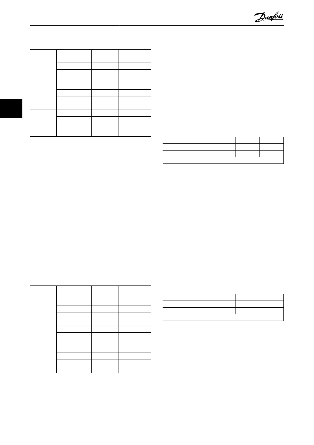
Edition Remarks Software version
MG90U1xx 1½ slot 1.xx
MG90U3xx 1 slot 2.00-2.11
MG92D1xx 1 slot 3.0x
Table 1.1 Document and Software Version
1.4 Product Overview
This programming guide relates to PROFINET interface
ordering number 130B1135 (uncoated), ordering number
130B1235 (conformal coated), and to the FCD 302
PROFINET interface.
The PROFINET interface is designed to communicate with
any system complying with the PROFINET schema version
2.2 and 2.3 standards.
Since the introduction in 2001, PROFINET has been
updated to handle low and medium performance
requirement supported by PROFINET RT up to high-end
servo performance in PROFINET IRT. PROFINET is the
Ethernet-based Fieldbus offering the most scalable and
versatile technology today.
PROFINET provides the network tools to deploy standard
Ethernet technology for manufacturing applications while
enabling Internet and enterprise connectivity.
The VLT® Programming Guide provides greater
•
detail on working with parameters and many
application examples.
The VLT® PROFINET MCA 120 Installation Guide
•
provides information about installing the
PROFINET and troubleshooting.
The VLT® PROFINET MCA 120 Programming Guide
•
provides information about configuring the
system, controlling the frequency converter,
parameter access, programming, troubleshooting,
as well as some typical application examples.
Supplementary publications and manuals are available
from Danfoss. See vlt-drives.danfoss.com/Support/Technical-
Documentation/ for listings.
1.3
Document and Software Version
This manual is regularly reviewed and updated. All
suggestions for improvement are welcome. Table 1.1 shows
the document version and the corresponding software
version.
VLT® PROFINET MCA 120 is intended for use with:
VLT® HVAC Drive FC 102
•
VLT® Refrigeration Drive FC 103
•
VLT® AQUA Drive FC 202
•
VLT® AutomationDrive FC 301/302
•
VLT® Decentral Drive FCD 302
•
Terminology
In this manual, several terms for Ethernet are used.
PROFINET, is the term used to describe the
•
PROFINET protocol.
Ethernet, is a common term used to describe the
•
physical layer of the network, and does not relate
to the application protocol.
MG92D102 Danfoss A/S © 10/2014 All rights reserved. 3
Page 6
Introduction
VLT® PROFINET MCA 120
1
1.5 Approvals and Certifications
More approvals and certifications are available. For more
information, contact a Danfoss local partner.
1.6 Symbols, Abbreviations and
Conventions
Abbreviation Definition
CC Control card
CTW Control word
DCP Discovery and configuration protocol
DHCP Dynamic host configuration protocol
EMC Electromagnetic compatibility
I/O Input/Output
IP Internet protocol
IRT Isochronous real time
LCP Local control panel
LED Light emitting diode
LSB Least significant bit
MAV Main actual value (actual speed)
MSB Most significant bit
MRV Main reference value
PC Personal computer
PCD Process control data
PLC Programmable logic controller
PNU Parameter number
PPO Process parameter object
REF Reference (=MRV)
RT Real time
STW Status word
Table 1.2 Symbols and Abbreviations
Conventions
Numbered lists indicate procedures.
Bullet lists indicate other information and description of
illustrations.
Italicised text indicates
cross reference
•
link
•
parameter name
•
4 Danfoss A/S © 10/2014 All rights reserved. MG92D102
Page 7
Safety Programming Guide
2 Safety
2.1 Safety Symbols
The following symbols are used in this document:
WARNING
Indicates a potentially hazardous situation that could
result in death or serious injury.
CAUTION
Indicates a potentially hazardous situation that could
result in minor or moderate injury. It can also be used to
alert against unsafe practices.
NOTICE
Indicates important information, including situations that
can result in damage to equipment or property.
2.2 Qualified Personnel
Correct and reliable transport, storage, installation,
operation, and maintenance are required for the troublefree and safe operation of the frequency converter. Only
qualified personnel are allowed to install or operate this
equipment.
Qualified personnel are defined as trained staff, who are
authorised to install, commission, and maintain equipment,
systems, and circuits in accordance with pertinent laws and
regulations. Additionally, the qualified personnel must be
familiar with the instructions and safety measures
described in this document.
2.3
Safety Precautions
WARNING
HIGH VOLTAGE
Frequency converters contain high voltage when
connected to AC mains input, DC supply, or load sharing.
Failure to perform installation, start-up, and maintenance
by qualified personnel can result in death or serious
injury.
Installation, start-up, and maintenance must be
•
performed by qualified personnel only.
WARNING
UNINTENDED START
When the frequency converter is connected to AC mains,
DC power supply, or load sharing, the motor may start at
any time. Unintended start during programming, service
or repair work can result in death, serious injury, or
property damage. The motor can start by means of an
external switch, a serial bus command, an input
reference signal from the LCP or LOP, via remote
operation using MCT 10 software, or after a cleared fault
condition.
To prevent unintended motor start:
Disconnect the frequency converter from mains.
•
Press [Off/Reset] on the LCP, before
•
programming parameters.
The frequency converter, motor, and any driven
•
equipment must be fully wired and assembled
when the frequency converter is connected to
AC mains, DC power supply, or load sharing.
WARNING
DISCHARGE TIME
The frequency converter contains DC-link capacitors,
which can remain charged even when the frequency
converter is not powered. Failure to wait the specified
time after power has been removed before performing
service or repair work, can result in death or serious
injury.
Stop motor.
•
Disconnect AC mains and remote DC-link power
•
supplies, including battery back-ups, UPS, and
DC-link connections to other frequency
converters.
Disconnect or lock PM motor.
•
Wait for the capacitors to discharge fully, before
•
performing any service or repair work. The
duration of waiting time is specified in the
relevant frequency converter operating
instructions,Chapter 2 Safety.
2 2
MG92D102 Danfoss A/S © 10/2014 All rights reserved. 5
Page 8

Safety
VLT® PROFINET MCA 120
WARNING
LEAKAGE CURRENT HAZARD
22
Leakage currents exceed 3.5 mA. Failure to ground the
frequency converter properly can result in death or
serious injury.
Ensure the correct grounding of the equipment
•
by a certified electrical installer.
WARNING
EQUIPMENT HAZARD
Contact with rotating shafts and electrical equipment
can result in death or serious injury.
Ensure that only trained and qualified
•
personnel perform installation, start up, and
maintenance.
Ensure that electrical work conforms to national
•
and local electrical codes.
Follow the procedures in this document.
•
CAUTION
INTERNAL FAILURE HAZARD
An internal failure in the frequency converter can result
in serious injury, when the frequency converter is not
properly closed.
Ensure that all safety covers are in place and
•
securely fastened before applying power.
6 Danfoss A/S © 10/2014 All rights reserved. MG92D102
Page 9
130BD782.10
Configuration
Programming Guide
3 Configuration
3.1 Configure the PROFINET Network
Ensure that all PROFINET devices connected to the same
bus network have a unique station name (host name).
Set the PROFINET host name of the frequency converter
via 12-08 Host Name, or via hardware switches.
3.2 Configure the Controller
3.2.1 GSDML File
To configure a PROFINET controller, the configuration tool
needs a GSDML file for each type of device on the
network. The GSDML file is a PROFINET xml file containing
the necessary communication setup data for a device.
Download the GSDML file for the FC 102, , FC 202, FC
301/302, and FCD 302 frequency converters at
www.danfoss.com/BusinessAreas/DrivesSolutions/profinet. The
name of the GSDML file can vary compared to this manual.
Download the latest version from the website.
The following example shows an FC 302. The steps for FCD
302 and the other frequency converter series are the same.
Frequency converter
series
FC 102
FC 202
FC 301/302
FCD 302 GSDML-V2.2-
Table 3.1 GSDML file
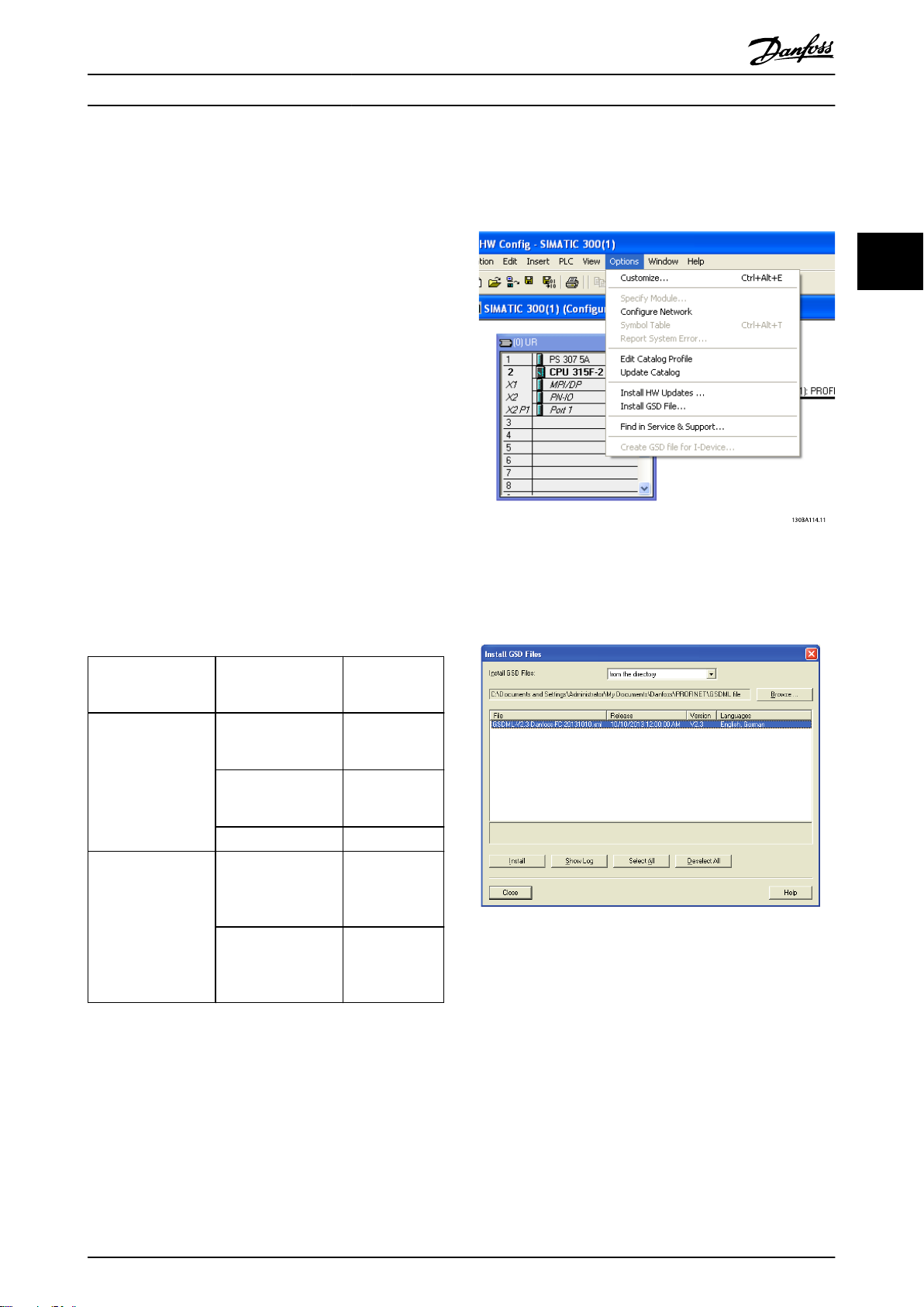
The first step in configuration of the PROFINET controller is
to import the GSDML file in the configuration tool. The
following steps outlined show how to add a new GSDML
file to the Simatic Manager software tool. For each
frequency converter series, a GSDML file is typically
imported once only, following the initial installation of the
software tool.
Firmware version
(15-61 Option SW
Version)
1.00-1.99 GSDML-V2.2-
2.00-2.15 GSDML-V2.3-
2.15
GSDML-V2.3-
GSDML file
FC-20090620.xml
FC-20131010.xml
FCD-20090620.x
FCD-20131010.x
Danfoss-
Danfoss-
Danfoss-
ml
Danfoss-
ml
3 3
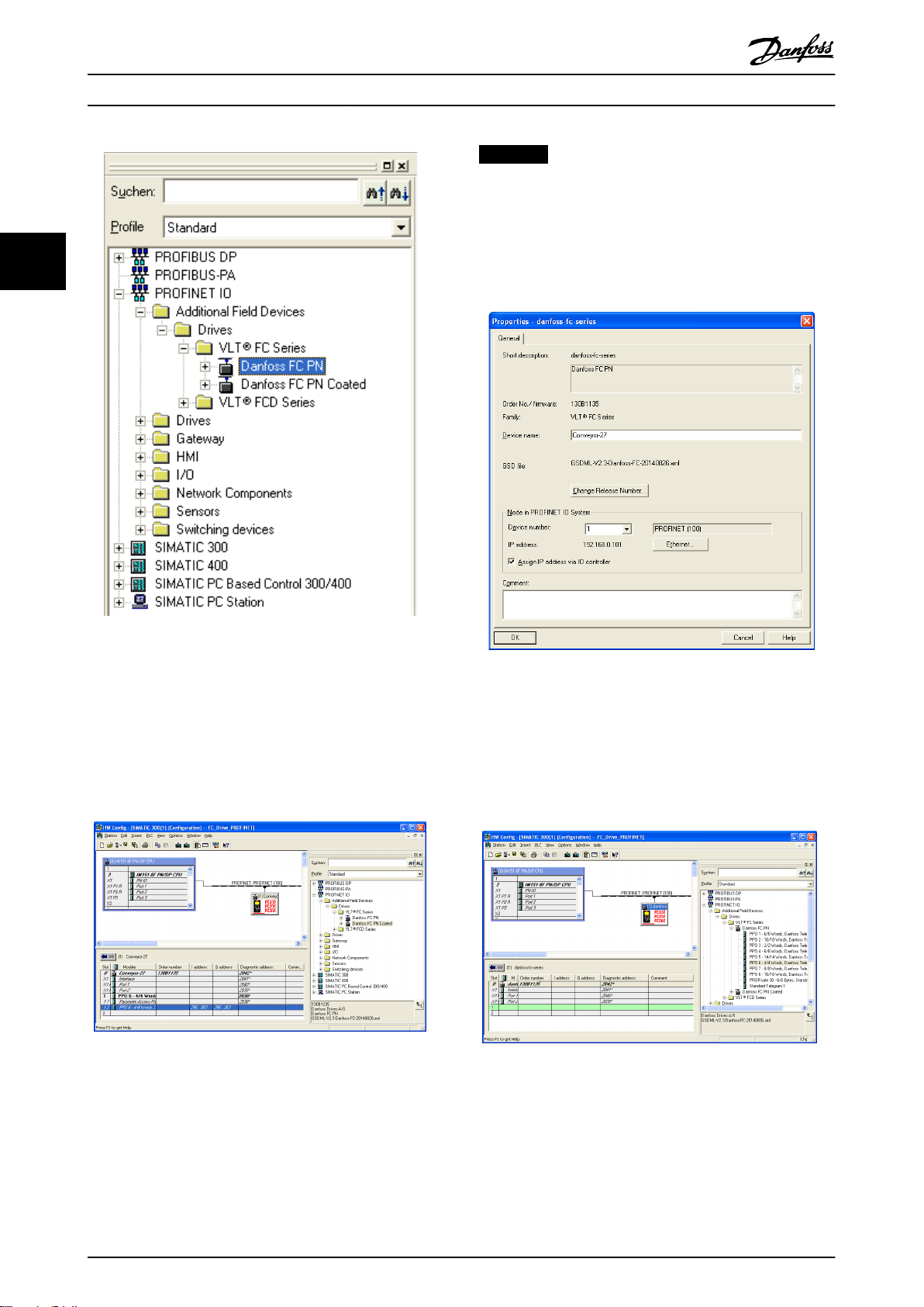
Illustration 3.1 Import the GSDML File in the Configuration
Tool
Illustration 3.2 Add a New GSDML File to the Simatic Manager
Software Tool
The FC 102//FC 202/FC 301/FC 302/FCD 302 GSDML file is
now imported and is accessible via the following path in
the hardware catalogue:
MG92D102 Danfoss A/S © 10/2014 All rights reserved. 7
Page 10
130BE027.10
130BE030.10
130BE028.10
130BE029.10
Configuration
VLT® PROFINET MCA 120
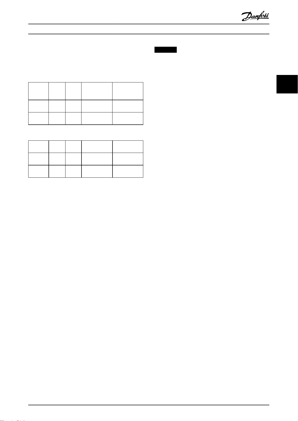
NOTICE
The name must match the name in 12-08 Host Name. If
the check mark Assign IP address via the IO controller is
set, the controller downloads the IP address to the IO
device with the corresponding device name. The IP
33
address is stored in the non-volatile memory of the
frequency converters.
Illustration 3.3 Path in the Hardware Catalogue
Open a project, set up the hardware, and add a PROFINET
Master system. Select Danfoss FC PN, then drag and drop
it onto the PROFINET IO system.
To enter the device name, open the properties for the
inserted frequency converter. See Illustration 3.4.
Illustration 3.4 Open the Properties for the Inserted
Frequency Converter to Enter the Device Name
Illustration 3.5 Set Up the Hardware and add a PROFINET
Master System
The next step is to set up the peripheral input and output
data. Data set up in the peripheral area is transmitted
cyclically via telegrams/PPO types. In the example below, a
PPO type 6 is dragged and dropped to slot 1.
Illustration 3.6 Set up the Peripheral Input and Output Data
8 Danfoss A/S © 10/2014 All rights reserved. MG92D102
Page 11
Configuration Programming Guide
The configuration tool automatically assigns addresses in
the peripheral address area. In this example the input and
output area have the following configuration:
PPO type 6
PCD word
number
Input
address
Set-up STW MAV
Table 3.2 PCD Read (VLT to PLC)
PCD word
number
Output
address
Set-up CTW MRV
Table 3.3 PCD Write (PLC to VLT)
0 1 2 3
256–257 258–
259
0 1 2 3
256–
257
258–
259
260–261 262–263
9-16 PCD Read
Configuration
260–261 262–263
9-15 PCD Write
Configuration
9-16 PCD Read
Configuration
9-15 PCD Write
Configuration
NOTICE
When 8-01 Control Site is set to [2] Control word only,
then the settings in Parameter8-50 Coasting Select to
Parameter 8-56 Preset Reference Select is overruled, and
only act on Bus-control.
3 3
Assign the PCDs via 9-16 PCD Read Configuration for inputs
and 9-15 PCD Write Configuration for outputs.
Download the configuration file to the PLC. The PROFINET
system starts data exchange when the PLC is set to Run
mode.
3.3
Configure the Frequency Converter
3.3.1 VLT Parameters
The following parameters are important when configuring
the frequency converter with a PROFINET interface.
0-40 [Hand on] Key on LCP. If [Hand On] is
•
activated, control of the frequency converter via
the PROFINET interface is disabled.
After an initial power-up, the frequency converter
•
automatically detects whether a fieldbus option is
installed in slot A, and sets parameter 8-02 Control
Word Source to [Option A]. When an option is
added, changed, or removed from an already
commissioned frequency converter, it does not
change parameter 8-02 Control Word Source but
enters Trip mode, and the frequency converter
displays an error
Parameter 8-10 Control Word Profile. Select
•
between the Danfoss frequency converter profile
and the PROFIdrive profile
8-50 Coasting Select to 8-56 Preset Reference Select.
•
Select how to gate PROFINET control commands
with the digital input command of the control
card.
MG92D102 Danfoss A/S © 10/2014 All rights reserved. 9
Page 12

Control
4 Control
VLT® PROFINET MCA 120
4.1 PPO Types
The PROFIBUS profile for frequency converters specifies a
number of communication objects (parameter process data
objects, PPO). The PROFIBUS profile for frequency
44
converters is suitable for data exchange between a process
controller (for example PLC) and a frequency converter. All
PPOs are defined for cyclic data transfer (that is, DP V0), so
that process data (PCD) and parameters (PCA) can be
transferred from the master to the slave and vice versa.
Pure process data objects
PPO types 3, 4, 6, 7 and 8 are pure process data objects
for applications requiring no cyclic parameter access. The
PLC sends out process control data, and the frequency
converter then responds with a PPO of the same length,
containing process status data.
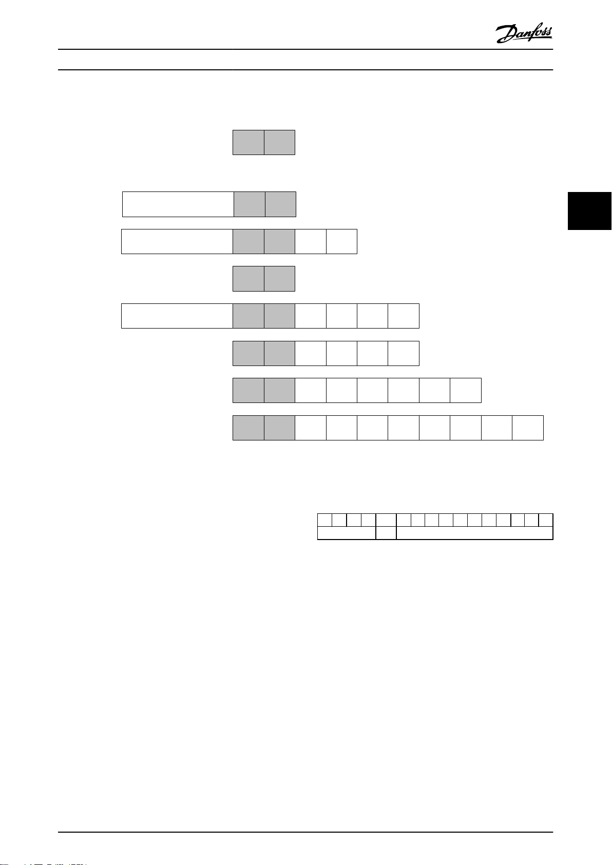
Illustration 4.1 shows the available PPO types:
PCD 1: The first 2 bytes of the process data area
•
(PCD 1) comprise a fixed part present in all PPO
types.
PCD 2: The next 2 bytes (PCD 2) are fixed for PCD
•
write entries (see 9-15 PCD Write Configuration
[1]), but configurable for PCD read entries (see
9-16 PCD Read Configuration [1]).
PCD 3-10: In the remaining bytes, from PCD 3
•
and on, the process data can be parameterised
with process signals, see
parameter 9-23 Parameters for Signals.
The signals for transmission from the master to the
frequency converter are determined by the setting in
9-15 PCD Write Configuration (request from master to the
frequency converter).
The signals for transmission from the frequency converter
to the master (response from the frequency converter to
master) are determined by the setting in 9-16 PCD Read
Configuration .
Parameter channel and process data
PPO types 1, 2, and 5 consist of a parameter channel and
process data. Use the parameter channel for reading
and/or updating of parameters (successively). Alternatively,
for better utilisation of I/O and thus PLC capacity, access
parameters via DP V1, by selecting a pure process data
object (PPO type 3, 4, 6, 7, or 8).
Select the PPO type in the master configuration. The
selection is automatically recorded in the frequency
converter. No manual setting of PPO types in the
frequency converter is required. Read the current PPO type
in parameter 9-22 Telegram Selection. The setting [1]
Standard telegram 1 is equivalent to PPO type 3.
In addition, all PPO types can be set up as word-consistent
or module-consistent. The process data area can be word
or module consistent, whereas the parameter channel
must always be module consistent.
Word-consistent data is transmitted as individual,
•
independent words between the PLC and the
frequency converter.
Module-consistent data is transmitted as sets of
•
interrelated words transferred simultaneously
between the PLC and the frequency converter.
10 Danfoss A/S © 10/2014 All rights reserved. MG92D102
Page 13
CTW/STW
REF/MAV
PCD 2
Read/
Write
PCD 3
Read/
Write
Standard telegram
1
PCD 4
Read/
Write
PCD 5
Read/
Write
PPO 4
PPO 6
PPO 7
PPO 8
Danfoss telegram
(The old PPO type 3)
PCV
CTW/STW REF/MAV
PCD 2
Read/
Write
PCD 3
Read/
Write
PCD 4
Read/
Write
PCD 5
Read/
Write
CTW/STW
REF/MAV
PCD 2
Read/
Write
PCD 3
Read/
Write
PCD 4
Read/
Write
PCD 5
Read/
Write
PCD 6
Read/
Write
PCD 7
Read/
Write
PCD 8
Read/
Write
PCD 9
Read/
Write
CTW/STW REF/MAV
PCD 2
Read/
Write
PCD 3
Read/
Write
PCD 4
Read/
Write
PCD 5
Read/
Write
PCD 6
Read/
Write
PCD 7
Read/
Write
CTW/STW REF/MAV
CTW/STW REF/MAV
PPO 3
CTW/STW REF/MAV
PCD 2
Read/
Write
PCD 3
Read/
Write
PPO 2
PCV
CTW/STW
REF/MAV
PPO 1
PCV
130BD911.10
Control Programming Guide
4 4
Illustration 4.1 Available PPO Types
4.2
PCV Parameter Access
The PROFINET cyclical data exchange performs parameter
access via the PCV channel. The PCV channel forms part of
the PPOs described in chapter 4 Control.
Use the PCV channel to read and write parameter values,
and read status for descriptive attributes of each
parameter.
4.2.1 PCA Handling
The PCA part of PPO types 1, 2, and 5 performs several
tasks. Using PCA, the master controls and supervises
parameters, and requests a response from the slave. Then
the slave responds to a request from the master. Requests
and responses is a handshake procedure and cannot be
batched. Therefore, when the master sends out a read/
write request, it must wait for the response before it sends
a new request. The request or response data value is
limited to maximum 4 bytes (see RC characteristics in
Table 4.1), which implies that text strings are not
transferable. For further information, see
chapter 7 Application Examples.
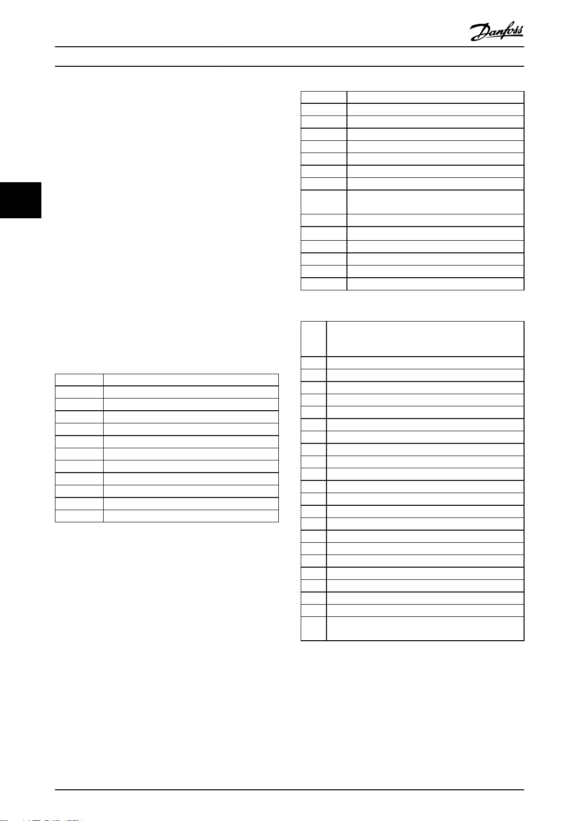
PCA - Parameter Characteristics
4.2.2
15 14 13 12 11 10 9 8 7 6 5 4 3 2 1 0
RC SMP PNU
Table 4.1 PCA - Parameter Characteristics
RC: Request/response characteristics (Range 0..15)
SMP: Spontaneous message (Not supported)
PNU : Parameter no. (Range 1..1999)
MG92D102 Danfoss A/S © 10/2014 All rights reserved. 11
Page 14
Control
VLT® PROFINET MCA 120
4.2.3 Request/Response Handling
The RC portion of the PCA word defines:
The requests issued from the master to the slave.
•
Other portions of the PCV involved:
•
PVA: The PVA portion transmits word-
-
size parameter values in bytes 7 and 8,
while long word size values require
44
RC Content
4.2.4
Request
The content of the RC portion of the PCA word for a
request is listed in Table 4.2.
Request Function
0 No request
1 Request parameter value
2 Change parameter value (word)
3 Change parameter value (long word)
4 Request description element
5 Change description element
6 Request parameter value (array)
7 Change parameter value (array word)
8 Change parameter value (array long word)
9 Request number of array elements
10-15 Not used
Table 4.2 Request
Response
When the slave rejects a request from the master, the RC
word in the PPO-read indicates the rejection by assuming
the value 7. Bytes 7 and 8 in the PVA element carry the
fault number.
The content of the RC portion of the PCA word for a
response is listed in Table 4.3.
bytes 5–8 (32 bits).
IND: When the response/request
-
contains array elements, the IND carries
the array sub-index. When parameter
descriptions are involved, the IND holds
the record sub-index of the parameter
description.
Response Function
0 No response
1 Transfer parameter value (word)
2 Transfer parameter value (long word)
3 Transfer description element
4 Transfer parameter value (array word)
5 Transfer parameter value (array long word)
6 Transfer number of array elements
7 Request rejected (including fault number, see
Table 4.4)
8 Not serviceable by PCV interface
9 Not used
10 Not used
11 Not used
12 Not used
13-15 Not used
Table 4.3 Response
Fault
Interpretation
numb
er
0 Illegal PNU
1 Parameter value cannot be changed.
2 Upper or lower limit exceeded.
3 Subindex corrupted.
4 No array
5 Data type false
6 Cannot be set by user (reset only).
7 Description element cannot be changed.
8 IR required PPO-write not available.
9 Description data not available.
10 Access group
11 No parameter write access
12 Key word missing.
13 Text in cyclical transmission not readable.
14 Name in cyclical transmission not readable.
15 Text array not available
16 PPO-write missing
17 Request temporarily rejected
18 Other fault
19 Data in cyclical transmission not readable.
130 There is no bus access to the parameter called.
131 Data change is not possible because factory set-up has
been selected.
Table 4.4 Fault Numbers
12 Danfoss A/S © 10/2014 All rights reserved. MG92D102
Page 15

Control Programming Guide
4.2.5 Example
This example shows
How to use PPO type 1 to change the ramp-up
•
time to 10 s, in 3-41 Ramp 1 Ramp Up Time.
How to command a start and speed reference of
•
50%.
Frequency converter parameter settings:
8-50 Coasting Select: Bus
Parameter 8-10 Control Word Profile: PROFIdrive profile
4.2.5.1
PCA parameter characteristics
PCA part (byte 1-2).
The RC part tells what the PCV part must be used for. The
functions available are listed in chapter 4.2.1 PCA Handling.
When a parameter is changed, select value 2 or 3. In this
example, 3 is selected, because 3-41 Ramp 1 Ramp Up Time
covers a long word (32 bits).
3-41 Ramp 1 Ramp Up Time=155 hex: In this example, byte
1 and 2 are set to 3155. See the values for bytes 1 and 2
in Table 4.5.
IND (bytes 3-4)
Used when reading/changing parameters with sub-index,
for example 9-15 PCD Write Configuration. In the example
bytes 3 and 4 are set to 00 hex. See the values for bytes 3
and 4 in Table 4.5.
PVA (bytes 5-8)
The data value of 3-41 Ramp 1 Ramp Up Time must be
changed to 10.00 s. The value transmitted must be 1000,
because the conversion index for 3-41 Ramp 1 Ramp Up
Time is 2. This means that the value received by the
frequency converter is divided by 100, such that the
frequency converter perceives 1000 as 10.00. Bytes
5-8=1000=03E8 hex. See chapter 6.6 Object and Data Types
Supported. See the values for bytes 5-8 in Table 4.5.
4.2.5.2
PCV
PCD
NOTICE
* For restart after power up:
Set bits 1 and 2 of the CTW to 1.
•
Toggle bit 0 from 0 to 1.
•
4.2.6 MRV
MRV is the speed reference, with data format Standardised
value. 0 hex=0% and 4000 hex=100%.
In the example, 2000 hex is used, corresponding to 50% of
the maximum frequency in 3-03 Maximum Reference. See
the values for bytes 11 and 12 in Table 4.5.
The whole PPO therefore has the following values in hex:
Byte Value
PCA 1 31
PCA 2 55
IND 3 00
PCV
PCD
Table 4.5 Request Example: PPO Values in Hex
The process data within the PCD part acts immediately
upon the frequency converter, and can be updated from
the master as quickly as possible. The PCV part is a
handshake procedure, which means that the frequency
converter has to acknowledge the command, before a new
one can be written.
Table 4.5 shows a positive response to the request example
from Table 4.5.
IND 4 00
PVA 5 00
PVA 6 00
PVA 7 03
PVA 8 E8
CTW 9 04
CTW 10 7F
MRV 11 20
MVR 12 00
4 4
Control word (CTW) according to PROFIdrive profile:
Control words consist of 16 bits. The meaning of each bit
is explained in chapter 4.5.1 Control Word according to
PROFIdrive Profile (CTW) and chapter 4.5.2 Status Word
according to PROFIdrive Profile (STW). The following bit
pattern sets all necessary start commands:
0000 0100 0111 1111=047F hex.*
0000 0100 0111 1110=047E hex.*
0000 0100 0111 1111=047F hex. These are the values for
bytes 9 and 10 in Table 4.5.
Quick stop: 0000 0100 0110 1111=046F hex.
Stop: 0000 0100 0011 1111=043F hex.
MG92D102 Danfoss A/S © 10/2014 All rights reserved. 13
Page 16
Control
VLT® PROFINET MCA 120
Byte Value
PCA 1 21
PCA 2 55
IND 3 00
PCV
44
PCD
Table 4.6 Response Example: Positive Response
IND 4 00
PVA 5 00
PVA 6 00
PVA 7 03
PVA 8 E8
STW 9 0F
STW 10 07
MAV 11 20
MAR 12 00
The PCD part responds according to the state and parameterisation of the frequency converter.
PCV part response:
PCA: As the request telegram, but here the RC
•
part is taken from Table 4.3. In this example, RC is
2 hex, which is a confirmation that a parameter
value of the type long word (32 bit) has been
In this case, the fault number is 2, which means that the
upper or lower limit of the parameter is exceeded, see
Table 4.4.
4.3 Process Data
Use the process data part of the PPO to control and
monitor the frequency converter via the PROFIBUS.
4.3.1 Process Control Data
Process control data (PCD) is the process data sent from
the PLC to the frequency converter.
Master/slave
1 2 3 ....... 10
CTW MRV PCD ....... PCD
PCD write
Table 4.8 Process Control Data
PCD 1 contains a 16-bit control word, and each bit controls
a specific function of the frequency converter, see
chapter 4.4 Control Profile.
transferred. IND is not used in this example.
PVA: 03E8 hex in the PVA part tells that the value
•
of 3-41 Ramp 1 Ramp Up Time is 1000, which
PCD 2 contains a 16-bit speed setpoint in percentage
format. See chapter 4.3.3 Reference Handling.
corresponds to 10.00.
STW: 0F07 hex means that the motor is running
•
and there are no warnings or faults.
MAV: 2000 hex indicates that the output
•
frequency is 50% of the maximum reference.
The content of PCD 3 to PCD 10 is determined by the
settings in 9-15 PCD Write Configuration and 9-16 PCD Read
Configuration.
Process Status Data
4.3.2
Table 4.7 shows a negative response to the request
example from Table 4.5.
Byte Value
PCA 1 70
PCA 2 00
IND 3 00
PCV
PCD
Table 4.7 Response Example: Negative Response
IND 4 00
PVA 5 00
PVA 6 00
PVA 7 00
PVA 8 02
STW 9 0F
STW 10 07
MAV 11 20
MAR 12 00
RC is 7 hex, which means that the request has been
rejected, and the fault number can be found in the PVA
part.
Process status data is the process data sent from the
frequency converter, and contains information about the
current state.
Slave/master
1 2 3 ...... 10
STW MAV PCD ...... PCD
PCD read
Table 4.9 Process Status Data
PCD 1 contains a 16-bit status word, and each bit contains
information regarding a possible state of the frequency
converter.
PCD 2 contains per default the value of the current speed
of the frequency converter in percentage format (see
chapter 4.3.3 Reference Handling). PCD 2 can be configured
to contain other process signals.
The content of PCD 3 to PCD 10 is determined by the
settings in 9-16 PCD Read Configuration.
14 Danfoss A/S © 10/2014 All rights reserved. MG92D102
Page 17
Control
Programming Guide
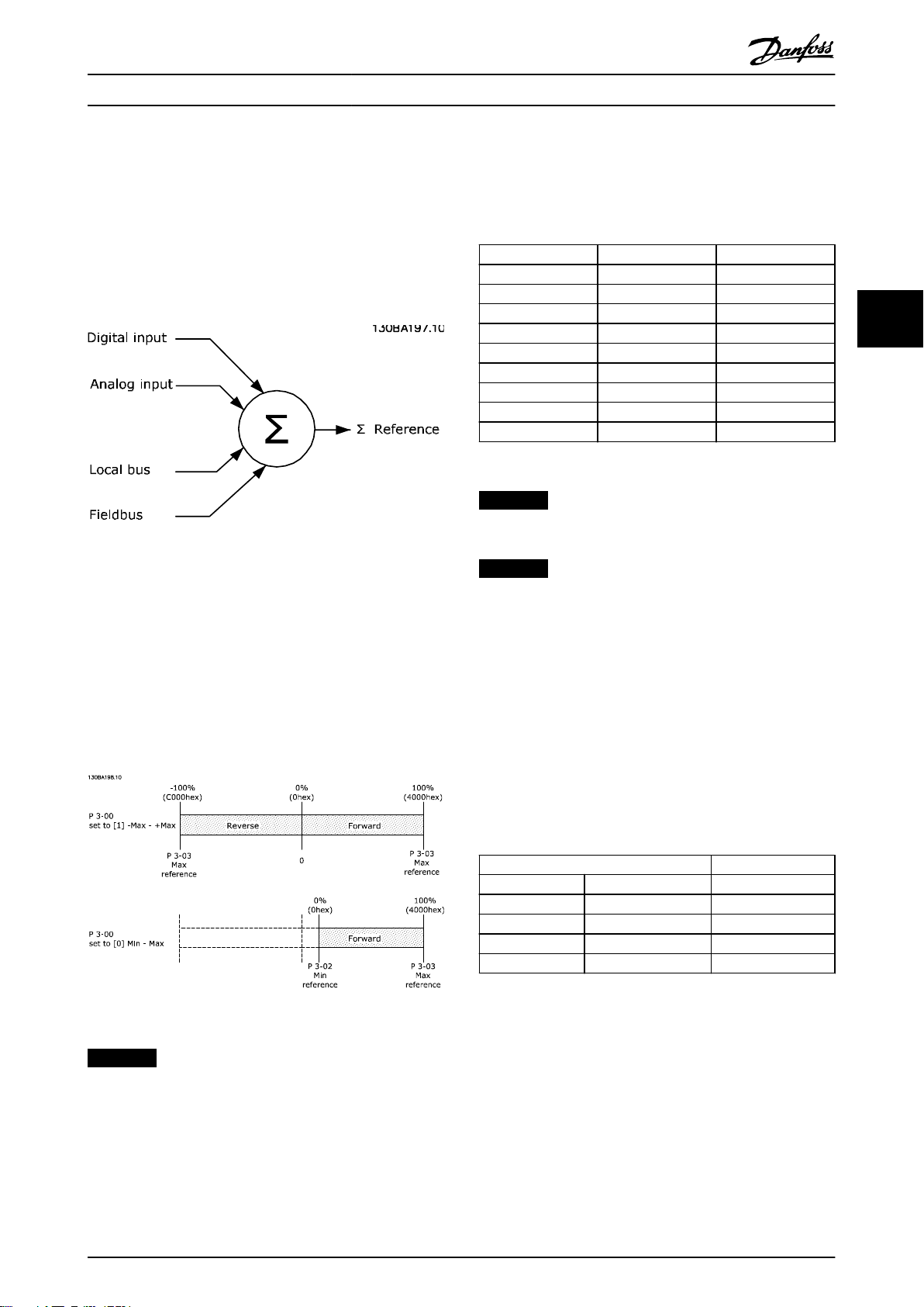
4.3.3 Reference Handling
The reference handling is an advanced mechanism that
sums up references from different sources, as shown in
Illustration 4.2.
For more information on reference handling, refer to the
design guide of the relevant frequency converter.
Illustration 4.2 Reference
The reference, or speed setpoint, is sent via PROFIBUS and
is always transmitted to the frequency converter in
percentage format as integers represented in hexadecimal
(0-4000 hex).
The final speed limit is set in
Table 4.10 lists the reference (MRV) and the feedback
(MAV) formats.
MRV/MAV Integer in hex Integer in decimal
100% 4000 16,384
75% 3000 12,288
50% 2000 8,192
25% 1000 4,096
0% 0 0
-25% F000 -4,096
-50% E000 -8,192
-75% D000 -12,288
-100% C000 -16,384
Table 4.10 Reference/Feedback (MRV/MAV) Format
4-19 Max Output Frequency.
NOTICE
Negative numbers are formed as complement of 2.
NOTICE
The data type for MRV and MAV is an N2 16-bit
standardised value, expressing a range from -200% to
+200% (8001 to 7FFF).
4 4
The reference (MRV) and feedback (MAV) are always scaled
equally. The setting of 3-00 Reference Range determines the
scaling of the reference and feedback (MAV), see
Illustration 4.3.
Illustration 4.3 Reference (MRV) and Feedback (MAV), Scaled
NOTICE
When 3-00 Reference Range is set to [0] Min - Max, a
negative reference is handled as 0%.
The actual output of the frequency converter is limited by
the speed limit parameters Motor Low/High Speed Limit
[RPM/Hz] in 4-11 Motor Speed Low Limit [RPM] to 4-14 Motor
Speed High Limit [Hz].
Example
The following settings determine the speed, as shown in
Table 4.11:
1-00 Configuration Mode set to [0] Speed open
•
loop.
3-00 Reference Range set to [0] Min-Max.
•
3-02 Minimum Reference set to 100 RPM.
•
3-03 Maximum Reference set to 3000 RPM.
•
MRV/MAV Actual speed [RPM]
0% 0 hex 100
25% 1000 hex 825
50% 2000 hex 1550
75% 3000 hex 2275
100% 4000 hex 3000
Table 4.11 Actual Speed for MRV/MAV
4.3.4
Process Control Operation
In process control operation, 1-00 Configuration Mode is set
to [3] Process.
The reference range in 3-00 Reference Range is always [0]
Min - Max.
MRV represents the process setpoint.
•
MAV expresses the actual process feedback
•
(range ±200%).
MG92D102 Danfoss A/S © 10/2014 All rights reserved. 15
Page 18
Control
4.3.5 Influence of the Digital Input
VLT® PROFINET MCA 120
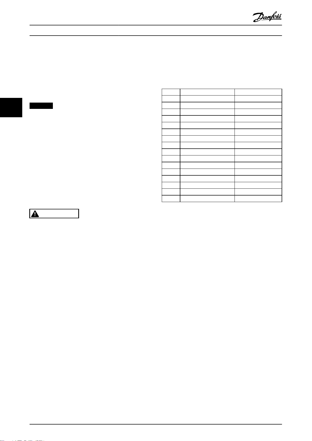
4.5.1
Control Word according to PROFIdrive
Profile (CTW)
Terminals upon FC Control Mode
The control word is used to send commands from a master
Set the influence of the digital input terminals upon
control of the frequency converter in 8-50 Coasting Select
to 8-56 Preset Reference Select.
44
NOTICE
The setting of 8-01 Control Site overrules the settings in
8-50 Coasting Select to 8-56 Preset Reference Select. The
setting of terminal 37 Coast stop (safe) overrules any
other parameter.
Each of the digital input signals can be programmed to
logic AND, logic OR, or to have no relation to the
corresponding bit in the control word. In this way the
following signal sources initiate a specific control
command, for example stop/coast:
Fieldbus only,
•
Fieldbus AND digital input, or
•
Either fieldbus OR digital input terminal.
•
(e.g. a PC) to a slave.
Bit Bit=0 Bit=1
00 OFF 1 ON 1
01 OFF 2 ON 2
02 OFF 3 ON 3
03 Coasting No coasting
04 Quick stop Ramp
05 Hold frequency output Use ramp
06 Ramp stop Start
07 No function Reset
08 Jog 1 OFF Jog 1 ON
09 Jog 2 OFF Jog 2 ON
10 Data invalid Data valid
11 No function Slow down
12 No function Catch up
13 Parameter set-up Selection lsb
14 Parameter set-up Selection msb
15 No function Reverse
CAUTION
To control the frequency converter via PROFIBUS, set
8-50 Coasting Select to either [1] Bus or to [2] Logic AND,
and set 8-01 Control Site to [0] or [2].
For more detailed information and examples of logical
relationship options, see chapter 8 Troubleshooting.
4.4
Control Profile
Control the frequency converter according to
the PROFIdrive profile, see chapter 4.5 PROFIdrive
•
Control Profile, or
the Danfoss FC control profile, see
•
chapter 4.6 FCDrive Control Profile.
Select the desired control profile in parameter 8-10 Control
Word Profile. The choice of profile affects the control word
and status word only.
chapter 4.5 PROFIdrive Control Profile and
chapter 4.6 FCDrive Control Profile provide a detailed
description of control and status data.
4.5
PROFIdrive Control Profile
This section describes the functionality of the control word
and status word in the PROFIdrive profile.
Table 4.12 Control Word Bits
Explanation of the control bits
Bit 00, OFF 1/ON 1
Normal ramp stops using the ramp times of the actual
selected ramp.
Bit 00="0" leads to the stop and activation of the output
relay 1 or 2 if the output frequency is 0 Hz and if [Relay
123] has been selected in 5-40 Function Relay.
When bit 0="1", the frequency converter is in State 1:
Switching on inhibited.
Refer to Illustration 4.4.
Bit 01, OFF 2/ON 2
Coasting stop.
When bit 01="0", a coasting stop and activation of the
output relay 1 or 2 occurs if the output frequency is 0 Hz
and if [Relay 123] has been selected in 5-40 Function Relay.
When bit 01="1", the frequency converter is in State 1:
Switching on inhibited. Refer to Illustration 4.4.
Bit 02, OFF 3/ON 3
Quick stop using the ramp time of 3-81 Quick Stop Ramp
Time.
When bit 02="0", a quick stop and activation of the output
relay 1 or 2 occurs if the output frequency is 0 Hz and if
[Relay 123] has been selected in 5-40 Function Relay.
When bit 02="1", the frequency converter is in State 1:
Switching on inhibited.
Refer to Illustration 4.4.
Bit 03, Coasting/no coasting
Coasting stop Bit 03="0" leads to a stop.
When bit 03="1", the frequency converter can start if the
other start conditions are fulfilled.
16 Danfoss A/S © 10/2014 All rights reserved. MG92D102
Page 19

Control
Programming Guide
NOTICE
The selection in 8-50 Coasting Select determines how bit
03 is linked with the corresponding function of the
digital inputs.
Bit 04, Quick stop/ramp
Quick stop using the ramp time of 3-81 Quick Stop Ramp
Time.
When bit 04="0", a quick stop occurs.
When bit 04="1", the frequency converter can start if the
other start conditions are fulfilled.
NOTICE
The selection in parameter 8-51 Quick Stop Select
determines how bit 04 is linked with the corresponding
function of the digital inputs.
Bit 05, Hold frequency output/use ramp
When bit 05="0", the current output frequency is being
maintained even if the reference value is modified.
When bit 05="1", the frequency converter can perform its
regulating function again; operation occurs according to
the respective reference value.
Bit 06, Ramp stop/start
Normal ramp stop using the ramp times of the actual
ramp selected. In addition, If relay 123 is selected in
5-40 Function Relay, and if the output frequency is 0 Hz,
this bit activates output relays 01 or 04. Bit 06="0" leads to
a stop. When bit 06="1", the frequency converter can start
if the other start conditions are fulfilled.
NOTICE
The selection in 8-53 Start Select determines how bit 06
is linked with the corresponding function of the digital
inputs.
Bit 10=“1” causes the control word to be used. This
function is relevant, because the control word is always
contained in the telegram, regardless of which type of
telegram is used.
Bit 11, No function/slow down
Used to reduce the speed reference value by the amount
given in 3-12 Catch up/slow Down Value value.
When bit 11="0", no modification of the reference value
occurs.
When bit 11="1", the reference value is reduced.
Bit 12, No function/catch up
Used to increase the speed reference value by the amount
given in 3-12 Catch up/slow Down Value.
When bit 12="0", no modification of the reference value
occurs.
When bit 12="1", the reference value is increased.
If both slowing down and accelerating are activated (bit 11
and 12="1"), slowing down has priority, and the speed
reference value is reduced.
Bits 13/14, Set-up selection
Bits 13 and 14 are used to select between the 4 parameter
set-ups according to Table 4.13.
The function is only possible if Multi Set-up has been
selected in 0-10 Active Set-up. The selection in 8-55 Set-up
Select determines how bits 13 and 14 are linked with the
corresponding function of the digital inputs. Changing setup while running is only possible if the set-ups have been
linked in 0-12 This Set-up Linked to.
Set-up Bit 13 Bit 14
1 0 0
2 1 0
3 0 1
4 1 1
4 4
Bit 07, No function/reset
Reset after switching off. Acknowledges event in fault
buffer.
When bit 07="0", no reset occurs.
When there is a slope change of bit 07 to "1", a reset
occurs after switching off.
Bit 08, Jog 1 OFF/ON
Activation of the pre-programmed speed in 8-90 Bus Jog 1
Speed. JOG 1 is only possible if bit 04="0" and bits
00-03="1".
Bit 09, Jog 2 OFF/ON
Activation of the pre-programmed speed in 8-91 Bus Jog 2
Speed. JOG 2 is only possible if bit 04="0" and bits
00-03="1".
Bit 10, Data invalid/valid
Used to tell the frequency converter whether the control
word is to be used or ignored. Bit 10=“0” causes the
control word to be ignored, giving the opportunity to turn
off the control word when updating/reading parameters.
MG92D102 Danfoss A/S © 10/2014 All rights reserved. 17
Table 4.13 Parameter Set-ups
Bit 15, No function/reverse
Bit 15=0 causes no reversing.
Bit 15=1 causes reversing.
NOTICE
In the factory setting, reversing is set to digital in
parameter 8-54 Reversing Select.
NOTICE
Bit 15 causes reversing only when Ser. communication,
Logic or, or Logic and is selected.
4.5.2 Status Word according to PROFIdrive
Profile (STW)
The status word is used to notify a master (for example a
PC) about the status of a slave.
Page 20

Control
VLT® PROFINET MCA 120
Bit Bit=0 Bit=1
00 Control not ready Control ready
01 Drive not ready Drive ready
02 Coasting Enable
03 No error Trip
04 OFF 2 ON 2
05 OFF 3 ON 3
06 Start possible Start not possible
44
07 No warning Warning
08
09 Local operation Bus control
10 Out of frequency limit Frequency limit ok
11 No operation In operation
12 Drive OK Stopped, autostart
13 Voltage OK Voltage exceeded
14 Torque OK Torque exceeded
15 Timer OK Timer exceeded
Table 4.14 Status Word Bits
Speed ≠ reference
Speed = reference
with bit 00 of the control word being set to "0" and bit 01,
02 and 10 being set to "1".
Bit 07, No warning/warning
Bit 07=“0” means that there are no warnings.
Bit 07=“1” means that a warning has occurred.
Bit 08, Speed≠reference/speed=reference
When bit 08="0", the current speed of the motor deviates
from the set speed reference value. This may occur, for
example, when the speed is being changed during start/
stop through ramp up/down.
When bit 08="1", the current speed of the motor
corresponds to the set speed reference value.
Bit 09, Local operation/bus control
Bit 09="0" indicates that the frequency converter has been
stopped with [Stop] on the LCP, or that [Linked to hand] or
[Local] has been selected in 3-13 Reference Site.
When bit 09="1", the frequency converter can be
controlled through the serial interface.
Bit 10, Out of frequency limit/frequency limit OK
Explanation of the status bits
Bit 00, Control not ready/ready
When bit 00="0", bit 00, 01 or 02 of the control word is "0"
(OFF 1, OFF 2 or OFF 3) - or the frequency converter is
switched off (trip).
When bit 00="1", the frequency converter control is ready,
but there is not necessarily power supply to the unit
present (in the event of external 24 V supply of the control
system).
Bit 01, VLT not ready/ready
Same significance as bit 00, however, there is a supply of
the power unit. The frequency converter is ready when it
receives the necessary start signals.
Bit 02, Coasting/enable
When bit 02="0", bit 00, 01 or 02 of the control word is "0"
(OFF 1, OFF 2 or OFF 3 or coasting) - or the frequency
converter is switched off (trip).
When bit 02="1", bit 00, 01 or 02 of the control word is
"1"; the frequency converter has not tripped.
Bit 03, No error/trip
When bit 03="0", no error condition of the frequency
converter exists.
When bit 03="1", the frequency converter has tripped and
requires a reset signal before it can start.
Bit 04, ON 2/OFF 2
When bit 01 of the control word is "0", bit 04="0".
When bit 01 of the control word is "1", bit 04="1".
Bit 05, ON 3/OFF 3
When bit 02 of the control word is "0", bit 05="0".
When bit 02 of the control word is "1", bit 05="1".
Bit 06, Start possible/start not possible
If PROFIdrive has been selected in parameter 8-10 Control
Word Profile, bit 06 is "1" after a switch-off acknowl-
When bit 10="0", the output frequency is outside the limits
set in 4-52 Warning Speed Low and 4-53 Warning Speed
High.
When bit 10="1", the output frequency is within the
indicated limits.
Bit 11, No operation/operation
When bit 11="0", the motor does not turn.
When bit 11="1", the frequency converter has a start
signal, or the output frequency is higher than 0 Hz.
Bit 12, Drive OK/Stopped, autostart
When bit 12="0", there is no temporary overloading of the
inverter.
When bit 12="1", the frequency converter has stopped due
to overloading. However, the frequency converter has not
switched off (tripped) and starts again after the
overloading has ended.
Bit 13, Voltage OK/voltage exceeded
When bit 13="0", the voltage limits of the frequency
converter are not exceeded.
When bit 13="1", the direct voltage in the intermediate
circuit of the frequency converter is too low or too high.
Bit 14, Torque OK/torque exceeded
When bit 14="0", the motor torque is below the limit
selected in 4-16 Torque Limit Motor Mode and 4-17 Torque
Limit Generator Mode.
When bit 14="1", the limit selected in 4-16 Torque Limit
Motor Mode or 4-17 Torque Limit Generator Mode is
exceeded.
Bit 15, Timer OK/timer exceeded
When bit 15="0", the timers for the thermal motor
protection and thermal frequency converter protection
have not exceeded 100%.
When bit 15="1", 1 of the timers has exceeded 100%.
edgment, after activation of OFF2 or OFF3, and after
switching on the mains voltage. Start not possible is reset,
18 Danfoss A/S © 10/2014 All rights reserved. MG92D102
Page 21

130BD806.10
Control Programming Guide
4.5.3 PROFIdrive State Transition Diagram
In the PROFIdrive control profile, the control bits:
0-3 perform the basic start-up/power down functions.
•
4-15 perform application-oriented control.
•
Illustration 4.4 shows the basic state transition diagram, where control bits 0-3 control the transitions, and the corresponding
status bit indicates the actual state. The black bullets indicate the priority of the control signals, where fewer bullets indicate
lower priority, and more bullets indicate higher priority.
4 4
Illustration 4.4 PROFIdrive State Transition Diagram
MG92D102 Danfoss A/S © 10/2014 All rights reserved. 19
Page 22

Control
VLT® PROFINET MCA 120
4.6 FCDrive Control Profile
4.6.1 Control Word according to FC Profile
(CTW)
To select Danfoss FC protocol in the control word, set
parameter 8-10 Control Word Profile to [0] Frequency
converter profile. Use the control word to send commands
from a master (PLC or PC) to a slave (frequency converter).
44
Bit Bit value=0 Bit value=1
00 Reference value External selection lsb
01 Reference value External selection msb
02 DC brake Ramp
03 Coasting No coasting
04 Quick stop Ramp
05 Hold output frequency Use ramp
06 Ramp stop Start
07 No function Reset
08 No function Jog
09 Ramp 1 Ramp 2
10 Data invalid Data valid
11 No function Relay 01 active
12 No function Relay 04 active
13 Parameter set-up selection lsb
14 Parameter set-up selection msb
15 No function Reverse
Table 4.15 Bit Values for FC Control Word
Explanation of the control bits
Bits 00/01 Reference value
Bits 00 and 01 are used to select between the 4 reference
values, which are pre-programmed in 3-10 Preset Reference
according to Table 4.16.
Bit 03, Coasting
Bit 03=“0” - causes the frequency converter immediately to
coast the motor to a standstill.
Bit 03=“1” - enables the frequency converter to start the
motor if the other starting conditions have been fulfilled.
NOTICE
In 8-50 Coasting Select a selection is made to define how
bit 03 gates with the corresponding function on a digital
input.
Bit 04, Quick stop
Bit 04=“0” - causes a quick stop, ramping the motor speed
down to stop via 3-81 Quick Stop Ramp Time.
Bit 04=“1” - the frequency converter ramps the motor
speed down to stop via 3-42 Ramp 1 Ramp Down Time or
3-52 Ramp 2 Ramp Down Time.
Bit 05, Hold output frequency
Bit 05=“0” - causes the present output frequency (in Hz) to
freeze. The frozen output frequency can only be changed
with the digital inputs (5-10 Terminal 18 Digital Input to
5-15 Terminal 33 Digital Input) programmed to Speed up
and Speed down.
Bit 05=“1” - uses ramp.
NOTICE
If Freeze output is active, stop the frequency converter
with
Bit 03 Coasting stop.
•
Bit 02 DC braking.
•
Digital input (5-10 Terminal 18 Digital Input to
•
5-15 Terminal 33 Digital Input) programmed to
DC braking, Coasting stop, or Reset and coasting
stop.
NOTICE
In 8-56 Preset Reference Select a selection is made to
define how bit 00/01 gates with the corresponding
function on the digital inputs.
Bit 01 Bit 00 Programmed
ref. value
0 0 1
0 1 2
1 0 3
1 1 4
Table 4.16 Programmed Reference Values for Bits
Bit 02, DC brake
Bit 02=“0” - leads to DC braking and stop. Braking current
and duration are set in 2-01 DC Brake Current and 2-02 DC
Braking Time.
Bit 02=“1” - leads to ramping.
20 Danfoss A/S © 10/2014 All rights reserved. MG92D102
Parameter
[0] 3-10 Preset Reference
[1] 3-10 Preset Reference
[2] 3-10 Preset Reference
[3] 3-10 Preset Reference
Bit 06, Ramp stop/start
Bit 06=“0” - causes a stop in which the motor speed is
ramped down to stop via the selected ramp down
parameter.
Bit 06=“1" - permits the frequency converter to start the
motor, if the other starting conditions have been fulfilled.
NOTICE
In 8-53 Start Select, define how bit 06 Ramp stop/start
gates with the corresponding function on a digital input.
Bit 07, Reset
Bit 07="0" - does not cause a reset.
Bit 07="1" - causes the reset of a trip. Reset is activated on
the signal’s leading edge, that is, when changing from
logic "0" to logic "1".
Bit 08, Jog
Bit 08="0" - no function.
Bit 08="1" - 3-19 Jog Speed [RPM] determines the output
frequency.
Page 23

Control
Programming Guide
Bit 09, Selection of ramp 1/2
Bit 09="0" - ramp 1 is active (3-40 Ramp 1 Type to
3-47 Ramp 1 S-ramp Ratio at Decel. Start).
Bit 09="1" - ramp 2 (3-50 Ramp 2 Type to 3-57 Ramp 2 Sramp Ratio at Decel. Start) is active.
Bit 10, Data not valid/data valid
Tells the frequency converter whether it should use or
ignore the control word.
Bit 10="0" - the control word is ignored.
Bit 10="1" - the control word is used. This function is
relevant, because the control word is always contained in
the telegram, regardless of which type of telegram is used.
Thus, it is possible to turn off the control word, if it is not
wished to use it when updating or reading parameters.
Bit 11, Relay 01
Bit 11="0" - relay 01 not activated.
Bit 11="1" - relay 01 activated, provided control word bit
11 has been selected in 5-40 Function Relay.
Bit 12, Relay 04
Bit 12="0" - relay 04 has not been activated.
Bit 12="1" - relay 04 has been activated, provided Control
word bit 12 has been selected in 5-40 Function Relay.
Bit 13/14, Selection of set-up
Bits 13 and 14 are used to select from the 4 menu set-ups
according to Table 4.17:
The function is only possible when Multi-Set-ups is selected
in 0-10 Active Set-up.
Set-up Bit 14 Bit 13
1 0 0
2 0 1
3 1 0
4 1 1
Table 4.17 Selection of Set-up
NOTICE
In 8-55 Set-up Select, define how bit 13/14 gates with the
corresponding function on the digital inputs.
Bit 15 Reverse
Bit 15="0" - no reversing.
Bit 15="1" - reversing.
4.6.2
Status Word according to FC Profile
(STW)
The status word is used to inform the master (for example
a PC) of the operation mode of the slave (frequency
converter).
Refer to chapter 7 Application Examples for an example of a
status word telegram using PPO type 3.
Bit Bit=0 Bit=1
00 Control not ready Control ready
01 Frequency converter
not ready
02 Coasting Enable
03 No error Trip
04 No error Error (no trip)
05 Reserved 06 No error Triplock
07 No warning Warning
08 Speed reference Speed=reference
09 Local operation Bus control
10 Out of frequency limit Frequency limit ok
11 No operation In operation
12 Frequency converter OK Stopped, autostart
13 Voltage OK Voltage exceeded
14 Torque OK Torque exceeded
15 Timer OK Timer exceeded
Table 4.18 Definition of Status Bits
Frequency converter ready
Explanation of the status bits
Bit 00, Control not ready/ready
Bit 00="0" - the frequency converter has tripped.
Bit 00="1" - the frequency converter controls are ready, but
the power component is not necessarily receiving any
power supply (in case of 24 V external supply to controls).
Bit 01, frequency converter ready
Bit 01="0" - the frequency converter is not ready for
operation.
Bit 01="1" - the frequency converter is ready for operation,
but there is an active coasting command via the digital
inputs or via serial communication.
Bit 02, Coasting stop
Bit 02="0" - the frequency converter has released the
motor.
Bit 02="1" - the frequency converter can start the motor
when a start command is given.
Bit 03, No error/trip
Bit 03="0" - the frequency converter is not in fault mode.
Bit 03="1" - the frequency converter is tripped, and that a
reset signal is required to re-establish operation.
Bit 04, No error/error (no trip)
Bit 04="0" - the frequency converter is not in fault mode.
Bit 04=“1” - there is a frequency converter error but no
trip.
Bit 05, Not used
Bit 05 is not used in the status word.
Bit 06, No error/triplock
Bit 06="0" - the frequency converter is not in fault mode.
Bit 06=“1” - the frequency converter is tripped, and locked.
Bit 07, No warning/warning
Bit 07="0" - there are no warnings.
Bit 07="1" - a warning has occurred.
4 4
MG92D102 Danfoss A/S © 10/2014 All rights reserved. 21
Page 24

Control
Bit 08, Speed reference/speed = reference
Bit 08="0" - the motor runs, but the present speed is
different from the preset speed reference. It could, for
example, be the case while the speed ramps up/down
during start/stop.
Bit 08="1" - the present motor speed matches the preset
speed reference.
Bit 09, Local operation/bus control
44
Bit 09="0" - [Stop/Reset] is pressed on the LCP, or Local
control in 3-13 Reference Site is selected. It is not possible
to control the frequency converter via serial communication.
Bit 09="1" - it is possible to control the frequency
converter via the fieldbus/serial communication.
Bit 10, Out of frequency limit
Bit 10="0" - the output frequency has reached the value in
4-11 Motor Speed Low Limit [RPM] or 4-13 Motor Speed High
Limit [RPM].
Bit 10="1" - the output frequency is within the defined
limits.
Bit 11, No operation/in operation
Bit 11="0" - the motor is not running.
Bit 11="1" - the frequency converter has a start signal or
the output frequency is higher than 0 Hz.
Bit 12, frequency converter OK/stopped, auto start
Bit 12="0" - there is no temporary over-temperature on the
frequency converter.
Bit 12="1" - the frequency converter has stopped because
of over-temperature, but the frequency converter has not
tripped and resumes operation once the over-temperature
stops.
Bit 13, Voltage OK/limit exceeded
Bit 13="0" - there are no voltage warnings.
Bit 13="1" - the DC voltage in the frequency converters
intermediate circuit is too low or too high.
Bit 14, Torque OK/limit exceeded
Bit 14="0" - the motor current is lower than the torque
limit selected in 4-16 Torque Limit Motor Mode or
4-17 Torque Limit Generator Mode.
Bit 14="1" - the torque limits in 4-16 Torque Limit Motor
Mode and 4-17 Torque Limit Generator Mode are exceeded.
Bit 15, Timer OK/limit exceeded
Bit 15="0" - the timers for motor thermal protection and
frequency converter thermal protection, have not
exceeded 100%.
Bit 15="1" - 1 of the timers has exceeded 100%.
VLT® PROFINET MCA 120
22 Danfoss A/S © 10/2014 All rights reserved. MG92D102
Page 25

Acyclic Communication (DP-V... Programming Guide
5 Acyclic Communication (DP-V1)
PROFINET offers more to the cyclical data communication,
a cyclical communication. This feature is possible by an IO
controller (for example, PLC), as well as an IO Supervisor
(for example, PC Tool).
Cyclical communication means that data transfer takes
place all the time with a certain update rate. This function
is the known function normally used for quick update of
I/O process data. Acyclic communication means a one-time
event, used mainly for read/write on parameters from
process controllers, PC-based tools, or monitoring systems.
5.1 Features of an IO Controller System
Cyclic data exchange.
Acyclic read/write on parameters.
5 5
The acyclic connection is fixed and cannot be changed
during operation.
In general, an IO controller is used as process controller,
responsible for commands, speed reference, status of the
application, and so on (PLC or PC-based controller).
In the IO controller, acyclic connection can be used for
general parameter access in the slaves.
5.2
Features of an IO-Supervisor System
Initiate/abort acyclic connection.
Acyclic read/write on parameters.
The acyclic connection can be established dynamically
(initiated) or removed (aborted) even though an IO
controller is active on the network.
The acyclic connection is typically used for configuration or
commissioning tools for easy access to each parameter in
any slave in the system.
MG92D102 Danfoss A/S © 10/2014 All rights reserved. 23
Page 26

Acyclic Communication (DP-V...
VLT® PROFINET MCA 120
5.3 Addressing Scheme
The structure of a PROFINET IO device is shown in Illustration 5.1.
An IO device consists of a number of physical or virtual slots. Slot 0 is always present, and represents the basic unit. Each
slot contains a number of data blocks addressed by an index.
The master must address a variable in the slave as follows: /Slave address/Slot #/Index #
55
Illustration 5.1 PROFINET IO Device Structure
24 Danfoss A/S © 10/2014 All rights reserved. MG92D102
Page 27

Acyclic Communication (DP-V... Programming Guide
5.4 Acyclic Read/Write Request Sequence
A read or write service on a frequency converter parameter takes place as illustrated in Illustration 5.2.
5 5
Illustration 5.2 Acyclic Read/Write Request Sequence
Initiate a read or write on a frequency converter parameter by an acyclic write service on slot 0, index 47. If this write
request is valid, a positive write response without data is returned from the frequency converter immediately. If not, a
negative write response is returned from the frequency converter.
The frequency converter now interprets the PROFIdrive parameter channel part of the data unit, and start to perform this
command internally in the frequency converter.
As the next step, the master sends a read request. If the frequency converter is still busy performing the internal parameter
request, a negative response without data is returned from the frequency converter. This request is repeated by the master,
until the frequency converter has the response data ready for the frequency converter parameter request.
The following example shows the details of the telegrams needed for the read/write service.
MG92D102 Danfoss A/S © 10/2014 All rights reserved. 25
Page 28

Acyclic Communication (DP-V...
VLT® PROFINET MCA 120
5.5 Data Structure in the Acyclic Telegrams
The data structure for a write/read parameter request,
consists of 3 main blocks:
Header block
•
Parameter block
•
Data block
•
Arrange according to Table 5.1:
Word number
55
1 Header Request # Request ID
2 Header Axis # Param.
3 (Param. 1) Attribute # Elements
4 (Param. 1) Parameter number
5 (Param. 1) Subindex number
6 (Param. 2) Attribute # Elements
7 (Param. 2) Parameter number
8 (Param. 2) Subindex number
9 (Param. 3) Attribute # Elements
10 (Param. 3) Parameter number
11 (Param. 3) Subindex number
...
N (Data Param. 1) Format # Elements
N+1 (Data Param. 1) Data Data
N (Data Param. 2) Format # Elements
N+1 (Data Param. 2) Data Data
N (Data Param. 3) Format # Elements
N+1 (Data Param. 3) Data Data
N+1 (Data Param. 3) Data Data
N+1 (Data Param. 3) Data Data
Table 5.1 Request Telegram
5.6
Header
Request number
The master uses request # to handle the response from the
IO device. The IO device mirrors this number in its
response.
Request ID
1=request parameter
2=change parameter
Axis
Always leave this to 0 (zero).
Only used in multi-axis system.
Number of parameters
Number of parameters to read or write.
10=Value
20=Description
30=Text
Number of elements
The number of elements to read, when parameter is
indexed.
Attribute
Read attribute.
Parameter number
The number of the parameter to read.
Subindex
Pointer to the index.
5.8 Data Block
The data block is only needed for write commands. Set up
the data block information for each parameter to write.
Format
The format of the information to write:
2: Integer 8
3: Integer 16
4: Integer 32
5: Unsigned 8
6: Unsigned 16
7: Unsigned 32
9: Visible string
33: Normalised value 2 bytes
35: Bit sequence of 16 boolean variables
54: Time difference without date
For the individual frequency converter series, the
Programming Guide of the frequency converter contains a
table with parameter number, format, and other relevant
information.
Data
The actual value to transfer. The amount of data has to be
exactly the size requested in the parameter block. If the
size differs, the request generates an error.
On a successful transmission of a request command, the
master can read the response from the frequency
converter. The response does look very much like the
request command. The response only consists of 2 blocks,
the header and the data block.
5.7
Parameter Block
Provide the following 5 values for each parameter to read.
Attribute
Attribute to be read
26 Danfoss A/S © 10/2014 All rights reserved. MG92D102
Page 29

Acyclic Communication (DP-V...
1 Header Request # Request ID
2 Header Axis # Param.
3 (Data Param. 1) Format Error code
4 (Data Param. 1) Data Data
5 (Data Param. 2) Format Error code
6 (Data Param. 2) Data Data
7 (Data Param. 3) Format Error code
8 (Data Param. 3) Data Data
9 (Data Param. 3) Data Data
10 (Data Param. 3) Data Data
Table 5.2 Response Telegram
Programming Guide
Error code
If the IO device discovers an error during the execution of
the command, it sets the error code to the following
values:
0x00 Unknown parameter
0x01 Parameter is read-only
0x02 Value out of range due to max/min value
0x03 Wrong subindex
0x04 Parameter is no array
0x05 Wrong datatype (wrong data length)
0x06 It is not allowed to set this parameter (only reset)
0x07 Descriptive element is read-only
0x09 No description available (only value)
0x0b Process control not possible
0x0f No text array available (only value)
0x11 Not possible in current state
0x14 Value out of range due to drive state/configuration
0x15 Reply too long (more than 240 bytes)
0x16 Wrong parameter address (unknown or unsupported value
for attribute, element, parameter number, or subindex or
illegal combination
0x17 Illegal format (for writing)
0x18 Value amount not consistent
0x65 Wrong axis: action not possible with this axis
5 5
0x66 Unknown service request
0x67 This service is not possible with multi-parameter access
0x68 Parameter value cannot be read from bus
Table 5.3 Error Code
MG92D102 Danfoss A/S © 10/2014 All rights reserved. 27
Page 30

Parameters
VLT® PROFINET MCA 120
6 Parameters
6.1 Parameter Group 0-** Operation/Display
0-37 Display Text 1
Range: Function:
0* [0 -
66
In this parameter, it is possible to write an individual
25 ]
text string for display in the LCP or to be read via
serial communication. If to be displayed
permanently, select [37] Display Text 1 in 0-20 Display
Line 1.1 Small, 0-21 Display Line 1.2 Small, 0-22 Display
Line 1.3 Small, 0-23 Display Line 2 Large or
0-24 Display Line 3 Large. Parameter 0-37 Display Text
1 is linked to parameter 12-08 Host Name. Changing
parameter 12-08 Host Name changes
Parameter 0-37 Display Text 1 - but not in the other
direction.
6.2 Parameter Group 8-** Communication
and Option
8-02 Control Word Source
Option: Function:
When retrofitting a bus option into a
frequency converter that did not have a bus
option installed earlier, change the control to
bus-based. This is required for safety reasons
to avoid an accidental change.
[0] None
[1] FC RS485
[2] FC USB
[3] Option A
[4] Option B
[5] Option C0
[6] Option C1
[30] External Can
8-03 Control Word Timeout Time
8-01 Control Site
Option: Function:
The setting in this parameter overrides the
settings in parameter 8-50 Coasting Select to
parameter 8-56 Preset Reference Select.
[0] Digital and
ctrl.word
[1] Digital only Control by using digital inputs only.
[2] Controlword
only
Control by using both digital input and
control word.
Control by using control word only.
8-02 Control Word Source
Option: Function:
NOTICE
This parameter cannot be adjusted
while the motor is running.
Select the source of the control word: 1 of 2
serial interfaces or 4 installed options. During
initial power-up, the frequency converter
automatically sets this parameter to [3] Option
A, if it detects a valid fieldbus option installed
in slot A. When the option is removed, the
frequency converter detects a configuration
change, sets parameter 8-02 Control Word
Source to default setting RS485, and trips. If
an option is installed after initial power-up,
the setting of parameter 8-02 Control Word
Source does not change, but the frequency
converter trips and displays: Alarm 67, Option
Changed.
Range: Function:
1 s* [ 0.1 -
18000 s]
Enter the maximum time expected to pass
between the reception of 2 consecutive
telegrams. If this time is exceeded, it indicates
that the telegram communication has stopped.
The function selected in parameter 8-04 Control
Word Timeout Function is then carried out. A
valid control word triggers the time-out counter.
8-04 Control Word Timeout Function
Select the time-out function. The time-out function activates
when the control word fails to be updated within the time
period specified in parameter 8-03 Control Word Timeout Time.
Option: Function:
[0] Off Resumes control via serial bus (fieldbus or
standard) using the most recent control
word.
[1] Freeze output Freezes output frequency until communi-
cation resumes.
[2] Stop Stops with auto restart when communi-
cation resumes.
[3] Jogging Runs the motor at jog frequency until
communication resumes.
[4] Max. speed Runs the motor at maximum frequency until
communication resumes.
[5] Stop and trip Stops the motor, then resets the frequency
converter to restart: Via the fieldbus, via
[Reset], or via a digital input.
[7] Select setup 1 Changes the set-up upon reestablishment of
communication following a control word
28 Danfoss A/S © 10/2014 All rights reserved. MG92D102
Page 31

Parameters Programming Guide
8-04 Control Word Timeout Function
Select the time-out function. The time-out function activates
when the control word fails to be updated within the time
period specified in parameter 8-03 Control Word Timeout Time.
Option: Function:
timeout. If communication resumes after a
timeout, parameter 8-05 End-of-Timeout
Function defines whether to resume the setup used before the timeout, or to retain the
set-up endorsed by the timeout function.
[8] Select setup 2
[9] Select setup 3
[10] Select setup 4
[26] Trip
See [7] Select set-up 1
See [7] Select set-up 1
See [7] Select set-up 1
NOTICE
To change the set-up after a timeout, configure as
follows:
Set 0-10 Active Set-up to [9] Multi set-up and select the
relevant link in 0-12 This Set-up Linked to.
8-05 End-of-Timeout Function
Option: Function:
Select the action after receiving a valid control
word following a timeout. This parameter is
active only when 8-04 Control Timeout Function
is set to [7] Set-up 1, [8] Set-up 2, [9] Set-up 3 or
[10] Set-up 4.
[0] Hold set-
up
[1] * Resume
set-up
8-06 Reset Control Word Timeout
This parameter is active only when [0] Hold set-up has been
selected in parameter 8-05 End-of-Timeout Function.
Option: Function:
[0] * Do not reset
[1] Do reset Returns the frequency converter to the
8-07 Diagnosis Trigger
Option: Function:
Retains the set-up selected in 8-04 Control
Timeout Function and displays a warning, until
8-06 Reset Control Timeout toggles. Then the
frequency converter resumes its original set-up.
Resumes the set-up active before the timeout.
Retains the set-up specified in
parameter 8-04 Control Word Timeout Function,
following a control word timeout.
original set-up following a control word
timeout. The frequency converter performs
the reset and then immediately reverts to the
[0] Do not reset setting.
Enables and controls the frequency converter
diagnosis function.
8-07 Diagnosis Trigger
Option: Function:
[0] * Disable Extended diagnosis data are not sent even if
they appear in the frequency converter.
[1] Trigger on
alarms
[2] Trigger
alarm/warn.
Extended diagnosis data are sent when 1 or
more alarms appear.
Extended diagnosis data are sent if one or
more alarms/warnings appear.
8-08 Readout Filtering
If the speed feedback value readouts on fieldbus are fluctuating,
this function is used. Select filtered, if the function is required. A
power-cycle is required for changes to take effect.
Option: Function:
[0] Motor Data Std-
Filt.
[1] Motor Data LP-
Filter
Normal bus readouts.
Filtered bus readouts of the
following parameters:
16-10 Power [kW]
16-11 Power [hp]
16-12 Motor Voltage
16-14 Motor current
16-16 Torque [Nm]
16-17 Speed [RPM]
16-22 Torque [%]
16-25 Torque [Nm] High
8-10 Control Word Profile
Select the interpretation of the control and status words
corresponding to the installed fieldbus. Only the selections valid
for the fieldbus installed in slot A are visible in the LCP display.
For guidelines in selection of [0] Frequency converter profile and
[1] PROFIdrive profile, refer to the design guide of the related
product.
For additional guidelines in the selection of [1] PROFIdrive profile,
[5] ODVA and [7] CANopen DSP 402, see the installation guide for
the installed fieldbus.
Option: Function:
[0] * FC profile
[1] PROFIdrive profile
[5] ODVA
[7] CANopen DSP 402
[8] MCO
8-13 Configurable Status Word STW
The status word has 16 bits (0-15). Bits 5 and 12-15 are configurable. Each of these bits can be configured to any of the
following options.
Option: Function:
[0] No function The input is always low.
[1] Profile Default Depending on the profile set
in 8-10 Control Profile.
6 6
MG92D102 Danfoss A/S © 10/2014 All rights reserved. 29
Page 32

Parameters
VLT® PROFINET MCA 120
8-13 Configurable Status Word STW
The status word has 16 bits (0-15). Bits 5 and 12-15 are configurable. Each of these bits can be configured to any of the
following options.
Option: Function:
[2] Alarm 68 Only The input goes high
whenever Alarm 68 is active,
and goes low whenever
alarm 68 is not activated.
[3] Trip excl Alarm 68
[10] T18 DI status
[11] T19 DI status
[12] T27 DI status
[13] T29 DI status
66
[14] T32 DI status
[15] T33 DI status
[16] T37 DI status The input goes high
whenever terminal 37 has 0 V
and goes low whenever
terminal 37 has 24 V.
[21] Thermal warning
[30] Brake fault (IGBT)
[40] Out of ref range
[41] Load throttle active
[60] Comparator 0
[61] Comparator 1
[62] Comparator 2
[63] Comparator 3
[64] Comparator 4
[65] Comparator 5
[70] Logic Rule 0
[71] Logic Rule 1
[72] Logic Rule 2
[73] Logic Rule 3
[74] Logic Rule 4
[75] Logic Rule 5
[80] SL digital out A
[81] SL digital out B
[82] SL digital out C
[83] SL digital out D
[84] SL digital out E
[85] SL digital out F
[86] ATEX ETR cur. alarm
[87] ATEX ETR freq. alarm
[88] ATEX ETR cur. warning
[89] ATEX ETR freq. warning
[90] Safe Function active
[91] Safe Opt. Reset req.
8-14 Configurable Control Word CTW
Option: Function:
Selection of control word bit 10 if it
is active low or active high.
[0] None
8-14 Configurable Control Word CTW
Option: Function:
[1] * Profile default
[2] CTW Valid, active low
[3] Safe Option Reset
[4] PID error inverse
[5] PID reset I part
[6] PID enable
8-19 Product Code
Range: Function:
Size
related*
[0 2147483647]
Select [0] to readout the actual
fieldbus product code according
to the mounted fieldbus option.
Select [1] to read out the actual
Vendor ID.
8-46 BTM Transaction Status
Option: Function:
[0] * Off
[1] Transaction Started
[2] Transaction Comitting
[3] Transaction Timeout
[4] Err. Non-existing Par.
[5] Err. Par. Out of Range
[6] Transaction Failed
8-47 BTM Timeout
Range: Function:
60 s* [1 - 360 s] Select the BTM Timeout after a BTM
transaction has been started.
8-48 BTM Maximum Errors
Range: Function:
21* [0 - 21] Selects the maximum allowed number of bulk
transfer mode errors before aborting. If it is set to
maximum, there is no abort.
8-49 BTM Error Log
Range: Function:
0.255* [0.000 -
9999.255]
List of parameters that failed during
bulk transfer mode. The value after the
decimal break is the error code (255
means no error).
8-50 Coasting Select
Option: Function:
Select control of the coasting function via the
terminals (digital input) and/or via the bus.
[0] Digital
input
[1] Bus Activates start command via the serial
Activates start command via a digital input.
communication port or fieldbus option.
30 Danfoss A/S © 10/2014 All rights reserved. MG92D102
Page 33

Parameters Programming Guide
8-50 Coasting Select
Option: Function:
[2] Logic
AND
[3] * Logic OR Activates start command via the fieldbus/serial
Activates start command via the fieldbus/serial
communication port, AND additionally via one
of the digital inputs.
communication port OR via one of the digital
inputs.
8-51 Quick Stop Select
Select control of the Quick Stop function via the terminals
(digital input) and/or via the bus.
Option: Function:
[0] Digital input
[1] Bus
[2] Logic AND
[3] * Logic OR
8-52 DC Brake Select
Option: Function:
Select control of the DC brake via the terminals
(digital input) and/or via the fieldbus.
NOTICE
when 1-10 Motor Construction is set to [1]
PM non-salient SPM, only selection [0]
Digital input is available.
[0] Digital
input
[1] Bus Activates start command via the serial communi-
[2] Logic
AND
[3] Logic OR Activates start command via the fieldbus/serial
8-53 Start Select
Option: Function:
[0] Digital
input
[1] Bus Activates a start command via the serial
[2] Logic
AND
Activates start command via a digital input.
cation port or fieldbus option.
Activates start command via the fieldbus/serial
communication port, AND additionally via one of
the digital inputs.
communication port OR via one of the digital
inputs.
Select control of the frequency converter start
function via the terminals (digital input) and/or
via the fieldbus.
Activates a start command via a digital input.
communication port or fieldbus option.
Activates a start command via the fieldbus/serial
communication port, AND additionally via one
of the digital inputs.
8-53 Start Select
Option: Function:
[3] * Logic OR Activates a start command via the fieldbus/serial
communication port, OR via 1 of the digital
inputs.
8-54 Reversing Select
Option: Function:
[0] Digital
input
[1] Bus Activates the reverse command via the serial
[2] Logic
AND
[3] * Logic OR Activates the reverse command via the
Select control of the frequency converter
reverse function via the terminals (digital input)
and/or via the fieldbus.
communication port, or fieldbus option.
Activates the reverse command via the
fieldbus/serial communication port, AND
additionally via 1 of the digital inputs.
fieldbus/serial communication port, OR via 1 of
the digital inputs.
8-55 Set-up Select
Option: Function:
Select control of the frequency converter set-up
selection via the terminals (digital input) and/or
via the fieldbus.
[0] Digital
input
[1] Bus Activates the set-up selection via the serial
[2] Logic
AND
[3] * Logic OR Activate the set-up selection via the fieldbus/
Activates the set-up selection via a digital input.
communication port or fieldbus option.
Activates the set-up selection via the fieldbus/
serial communication port, AND additionally via
one of the digital inputs.
serial communication port OR via one of the
digital inputs.
8-56 Preset Reference Select
Option: Function:
Select control of the preset reference selection
via the terminals (digital input) and/or via the
fieldbus.
[0] Digital
input
[1] Bus Activates preset reference selection via the
[2] Logic
AND
[3] * Logic OR Activates the preset reference selection via the
Activates preset reference selection via a digital
input.
serial communication port or fieldbus option.
Activates preset reference selection via the
fieldbus/serial communication port, AND
additionally via one of the digital inputs.
fieldbus/serial communication port OR via one
of the digital inputs.
6 6
MG92D102 Danfoss A/S © 10/2014 All rights reserved. 31
Page 34

Parameters
VLT® PROFINET MCA 120
8-90 Bus Jog 1 Speed
Range: Function:
100 RPM* [ 0 - par. 4-13
RPM]
Enter the jog speed. Activate this
fixed jog speed via the serial port
or fieldbus option.
8-91 Bus Jog 2 Speed
Range: Function:
200 RPM* [ 0 - par. 4-13
RPM]
Enter the jog speed. Activate this
fixed jog speed via the serial port
or fieldbus option.
6.3 Parameter Group 9-** PROFIdrive
66
9-15 PCD Write Configuration
Array [10]
Option: Function:
Select the parameters to be assigned to PCD 3-10 of
the telegrams. The number of available PCDs depends
on the telegram type. The values in PCD 3-10 are then
written to the selected parameters as data values.
Alternatively, specify a standard PROFIBUS telegram in
9-22 Telegram Selection.
9-16 PCD Read Configuration
Array [10]
Option: Function:
Select the parameters to be assigned to PCD 3–10 of
the telegrams. The number of available PCDs depends
on the telegram type. PCDs 3–10 contain the actual
data values of the selected parameters. For standard
PROFIBUS telegram, see 9-22 Telegram Selection.
9-22 Telegram Selection
Option: Function:
This parameter shows the selected
standard PROFIBUS telegram that
the PROFINET IO controller has sent
to the frequency converter. At
power-up or if a non-supported
telegram is sent from the IO
controller this parameter shows
None in the display.
[1] Standard telegram
1
[100] * None
[101] PPO 1
[102] PPO 2
[103] PPO 3
[104] PPO 4
[105] PPO 5
[106] PPO 6
[107] PPO 7
[108] PPO 8
9-23 Parameters for Signals
Array [1000]
Read only
Option: Function:
This parameter
contains a list of
signals available for
selection in 9-15 PCD
Write Configuration
and 9-16 PCD Read
Configuration.
[0] * None
[15] Readout: actual setup
[302] Minimum Reference
[303] Maximum Reference
[312] Catch up/slow Down Value
[341] Ramp 1 Ramp Up Time
[342] Ramp 1 Ramp Down Time
[351] Ramp 2 Ramp Up Time
[352] Ramp 2 Ramp Down Time
[380] Jog Ramp Time
[381] Quick Stop Ramp Time
[411] Motor Speed Low Limit [RPM]
[412] Motor Speed Low Limit [Hz]
[413] Motor Speed High Limit [RPM]
[414] Motor Speed High Limit [Hz]
[416] Torque Limit Motor Mode
[417] Torque Limit Generator Mode
[553] Term. 29 High Ref./Feedb. Value
[558] Term. 33 High Ref./Feedb. Value
[590] Digital & Relay Bus Control
[593] Pulse Out #27 Bus Control
[595] Pulse Out #29 Bus Control
[597] Pulse Out #X30/6 Bus Control
[615] Terminal 53 High Ref./Feedb. Value
[625] Terminal 54 High Ref./Feedb. Value
[653] Term 42 Output Bus Ctrl
[663] Terminal X30/8 Bus Control
[673] Terminal X45/1 Bus Control
[683] Terminal X45/3 Bus Control
[748] PCD Feed Forward
[890] Bus Jog 1 Speed
[891] Bus Jog 2 Speed
[1472] Legacy Alarm Word
[1473] Legacy Warning Word
[1474] Leg. Ext. Status Word
[1500] Operating hours
[1501] Running Hours
[1502] kWh Counter
[1600] Control Word
[1601] Reference [Unit]
[1602] Reference %
[1603] Status Word
[1605] Main Actual Value [%]
32 Danfoss A/S © 10/2014 All rights reserved. MG92D102
Page 35

Parameters Programming Guide
9-23 Parameters for Signals
Array [1000]
Read only
Option: Function:
[1606] Absolute Position
[1609] Custom Readout
[1610] Power [kW]
[1611] Power [hp]
[1612] Motor Voltage
[1613] Frequency
[1614] Motor current
[1615] Frequency [%]
[1616] Torque [Nm]
[1617] Speed [RPM]
[1618] Motor Thermal
[1619] KTY sensor temperature
[1620] Motor Angle
[1621] Torque [%] High Res.
[1622] Torque [%]
[1623] Motor Shaft Power [kW]
[1624] Calibrated Stator Resistance
[1625] Torque [Nm] High
[1630] DC Link Voltage
[1632] Brake Energy /s
[1633] Brake Energy Average
[1634] Heatsink Temp.
[1635] Inverter Thermal
[1638] SL Controller State
[1639] Control Card Temp.
[1645] Motor Phase U Current
[1646] Motor Phase V Current
[1647] Motor Phase W Current
[1648] Speed Ref. After Ramp [RPM]
[1650] External Reference
[1651] Pulse Reference
[1652] Feedback[Unit]
[1653] Digi Pot Reference
[1657] Feedback [RPM]
[1660] Digital Input
[1661] Terminal 53 Switch Setting
[1662] Analog Input 53
[1663] Terminal 54 Switch Setting
[1664] Analog Input 54
[1665] Analog Output 42 [mA]
[1666] Digital Output [bin]
[1667] Freq. Input #29 [Hz]
[1668] Freq. Input #33 [Hz]
[1669] Pulse Output #27 [Hz]
[1670] Pulse Output #29 [Hz]
[1671] Relay Output [bin]
[1672] Counter A
[1673] Counter B
[1674] Prec. Stop Counter
[1675] Analog In X30/11
9-23 Parameters for Signals
Array [1000]
Read only
Option: Function:
[1676] Analog In X30/12
[1677] Analog Out X30/8 [mA]
[1678] Analog Out X45/1 [mA]
[1679] Analog Out X45/3 [mA]
[1680] Fieldbus CTW 1
[1682] Fieldbus REF 1
[1684] Comm. Option STW
[1685] FC Port CTW 1
[1686] FC Port REF 1
[1687] Bus Readout Alarm/Warning
[1689] Configurable Alarm/Warning Word
[1690] Alarm Word
[1691] Alarm Word 2
[1692] Warning Word
[1693] Warning Word 2
[1694] Ext. Status Word
[1836] Analog Input X48/2 [mA]
[1837] Temp. Input X48/4
[1838] Temp. Input X48/7
[1839] Temp. Input X48/10
[1860] Digital Input 2
[3310] Sync Factor Master
[3311] Sync Factor Slave
[3401] PCD 1 Write to MCO
[3402] PCD 2 Write to MCO
[3403] PCD 3 Write to MCO
[3404] PCD 4 Write to MCO
[3405] PCD 5 Write to MCO
[3406] PCD 6 Write to MCO
[3407] PCD 7 Write to MCO
[3408] PCD 8 Write to MCO
[3409] PCD 9 Write to MCO
[3410] PCD 10 Write to MCO
[3421] PCD 1 Read from MCO
[3422] PCD 2 Read from MCO
[3423] PCD 3 Read from MCO
[3424] PCD 4 Read from MCO
[3425] PCD 5 Read from MCO
[3426] PCD 6 Read from MCO
[3427] PCD 7 Read from MCO
[3428] PCD 8 Read from MCO
[3429] PCD 9 Read from MCO
[3430] PCD 10 Read from MCO
[3440] Digital Inputs
[3441] Digital Outputs
[3450] Actual Position
[3451] Commanded Position
[3452] Actual Master Position
[3453] Slave Index Position
[3454] Master Index Position
6 6
MG92D102 Danfoss A/S © 10/2014 All rights reserved. 33
Page 36

Parameters
VLT® PROFINET MCA 120
9-23 Parameters for Signals
Array [1000]
Read only
Option: Function:
[3455] Curve Position
[3456] Track Error
[3457] Synchronizing Error
[3458] Actual Velocity
[3459] Actual Master Velocity
[3460] Synchronizing Status
[3461] Axis Status
[3462] Program Status
[3464] MCO 302 Status
[3465] MCO 302 Control
66
[3470] MCO Alarm Word 1
[3471] MCO Alarm Word 2
[4280] Safe Option Status
[4282] Safe Control Word
[4283] Safe Status Word
[4285] Active Safe Func.
9-27 Parameter Edit
Option: Function:
Parameters can be edited via Profibus, the
standard RS-485 interface, or the LCP.
[0] Disabled Disables editing via Profibus.
[1] * Enabled Enables editing via Profibus.
Bit Condition when bit is active
0 Connection with IO controller is not ok
1 Reserved for status of connection with second IO
controller
2 Not used
3 Clear data command received
4 Actual value is not updated
5 No link on both port
6 Not used
7 Initialising of PROFINET is not ok
8 Drive is tripped
9 Internal CAN error
10 Wrong configuration data from IO controller
11 Not used
12 Internal error occurred
13 Not configured
14 Timeout active
15 Warning 34 active
Table 6.1 PROFINET Communication Warnings
9-65 Profile Number
Range: Function:
0* [0 - 0 ] This parameter contains the profile identification.
Byte 1 contains the profile number and byte 2 the
version number of the profile.
NOTICE
This parameter is not visible via LCP.
9-28 Process Control
Option: Function:
Process control (setting of control word, speed
reference, and process data) is possible via either
PROFINET or standard fieldbus, but not both
simultaneously. Local control is always possible
via the LCP. Control via process control is possible
via either terminals or fieldbus depending on the
settings in parameter 8-50 Coasting Select to
parameter 8-56 Preset Reference Select.
[0] Disable Disables process control via PROFINET, and
enables process control via standard fieldbus or
PROFINET IO supervisor.
[1]*Enable
cyclic
master
Enables process control via IO controller, and
disables process control via standard fieldbus or
PROFINET IO supervisor.
9-70 Programming Set-up
Option: Function:
Select the set-up to be edited.
[0] Factory setup Uses default data. This option can be used
as a data source to return the other set-ups
to a known state.
[1] Set-up 1 Edits Set-up 1.
[2] Set-up 2 Edits Set-up 2.
[3] Set-up 3 Edits Set-up 3.
[4] Set-up 4 Edits Set-up 4.
[9] * Active Set-up Follows the active set-up selected in
0-10 Active Set-up.
This parameter is unique for LCP and fieldbus. See
9-53 Profibus Warning Word
Range: Function:
0* [0 - 65535 ] This parameter displays PROFINET communi-
cation warnings.
Read only
0-11 Programming Set-up.
9-71 Profibus Save Data Values
Option: Function:
Parameter values changed via PROFINET are not
automatically stored in non-volatile memory.
Use this parameter to activate a function that
stores parameter values in the EEPROM non-
34 Danfoss A/S © 10/2014 All rights reserved. MG92D102
Page 37

Parameters Programming Guide
9-71 Profibus Save Data Values
Option: Function:
volatile memory, so changed parameter values
are retained at power-down.
[0] * Off Deactivates the non-volatile storage function.
[1] Store all
setups
[2] Store all
setups
Stores all parameter values for all set-ups in the
non-volatile memory. When all parameter values
have been stored, the selection returns to [0]
Off.
Stores all parameter values for all set-ups in the
non-volatile memory. When all parameter values
have been stored, the selection returns to [0]
Off.
9-72 ProfibusDriveReset
Option: Function:
[0] * No action
[1] Power-on
reset
[3] Comm
option reset
Resets frequency converter upon power-up,
as for power-cycle.
Resets the PROFINET option only, the
PROFINET option goes through a power-up
sequence.
When reset, the frequency converter
disappears from the fieldbus, which may
cause a communication error from the
master.
9-83 Defined Parameters (4)
Array [116]
No LCP access
Read only
Range: Function:
0* [0 - 9999 ] This parameter displays a list of all the defined
frequency converter parameters available for
PROFINET.
9-84 Defined Parameters (5)
Array [115]
No LCP access
Read only
Range: Function:
0* [0 - 9999] This parameter displays a list of all the defined
frequency converter parameters available for
PROFINET.
9-90 Changed Parameters (1)
Array [116]
No LCP access
Read only
Range: Function:
0* [0 - 9999 ] This parameter displays a list of all the
frequency converter parameters deviating from
default setting.
6 6
9-80 Defined Parameters (1)
Array [116]
No LCP access
Read only
Range: Function:
0* [0 - 9999 ] This parameter displays a list of all the defined
frequency converter parameters available for
PROFINET.
9-81 Defined Parameters (2)
Array [116]
No LCP access
Read only
Range: Function:
0* [0 - 9999 ] This parameter displays a list of all the defined
frequency converter parameters available for
PROFINET.
9-82 Defined Parameters (3)
Array [116]
No LCP access
Read only
Range: Function:
0* [0 - 9999 ] This parameter displays a list of all the defined
frequency converter parameters available for
PROFINET.
9-91 Changed Parameters (2)
Array [116]
No LCP access
Read only
Range: Function:
0* [0 - 9999 ] This parameter displays a list of all the
frequency converter parameters deviating from
default setting.
9-92 Changed Parameters (3)
Array [116]
No LCP access
Read only
Range: Function:
0* [0 - 9999 ] This parameter displays a list of all the
frequency converter parameters deviating from
default setting.
9-94 Changed Parameters (5)
Array [116]
No LCP Address
Read only
Range: Function:
0* [0 - 9999 ] This parameter displays a list of all the
frequency converter parameters deviating from
default setting.
MG92D102 Danfoss A/S © 10/2014 All rights reserved. 35
Page 38

Parameters
VLT® PROFINET MCA 120
6.4 Parameter Group 12-** Ethernet
6.4.1 12-0* IP Settings
12-07 Domain Name
Range: Function:
0 [0 - 48] Domain name of the attached network. Can be
automatically assigned when using DHCP network.
12-00 IP Address Assignment
Option: Function:
Selects the IP address assignment method.
[0] MANUAL
[1] DHCP IP-address is assigned via DHCP server.
[2] BOOTP IP-address is assigned via BOOTP server.
[10] DCP
[20] From node ID
66
12-01 IP Address
IP-address can be set in parameter 12-01 IP
Address IP Address.
Range: Function:
0* [0 -
2147483647 ]
Configure the IP address of the option.
Read-only if parameter 12-00 IP Address
Assignment set to DHCP or BOOTP. In
POWERLINK, the IP address follows the
12-60 Node ID last byte and the first part is
fixed to 192.168.100 (node ID).
12-08 Host Name
Range: Function:
0* [0 - 48 ] Logical (given) name of option.
NOTICE
The display of the frequency converter only shows the
first 19 characters, but the remaining characters are
stored in the frequency converter. If hardware switches
are different from all ON or all OFF, the switches have
priority.
12-09 Physical Address
Range: Function:
0* [0 - 17] Read-only. Displays the physical (MAC) address of
the option.
6.4.2 12-1* Ethernet Link Parameters
12-02 Subnet Mask
Range: Function:
0* [0 -
4244635647]
Configure the IP subnet mask of the
option. Read-only if parameter 12-00 IP
Address Assignment set to DHCP or BOOTP.
In POWERLINK it is fixed to 255.255.255.0.
12-03 Default Gateway
Range: Function:
0* [0 -
2147483647 ]
Configure the IP default gateway of the
option. Read-only if parameter 12-00 IP
Address Assignment set to DHCP or BOOTP.
In a non-routed network this address is set
to the IP address of the IO Device
12-04 DHCP Server
Range: Function:
0* [0 - 2147483647 ] Read only. Displays the IP address of the
found DHCP or BOOTP server.
12-05 Lease Expires
Range: Function:
Size related* [ 0 - 0]
12-06 Name Servers
Range: Function:
0* [0 - 2147483647] IP addresses of Domain Name Servers.
Can be automatically assigned when
using DHCP.
Applies for the whole parameter group.
Index [0] is used for port 1, and Index [1] is used for port
2. For EtherCAT, index [0] is for the in-port and index [1] is
for the out-port.
12-10 Link Status
Option: Function:
Read-only. Displays the link status of the Ethernet
ports.
[0] * No Link
[1] Link
12-11 Link Duration
Range: Function:
Size related* [ 0 - 0] Read-only. Displays the duration of the
present link on each port in dd:hh:mm:ss.
12-12 Auto Negotiation
Option: Function:
Configures auto negotiation of Ethernet link
parameters, for each port: ON or OFF.
[0] Off
[1] * On
Link Speed and Link Duplex can be configured in
parameter 12-13 Link Speed and 12-14 Link Duplex.
NOTICE
In POWERLINK, this parameter is fixed to OFF setting.
36 Danfoss A/S © 10/2014 All rights reserved. MG92D102
Page 39

Parameters Programming Guide
12-13 Link Speed
Option: Function:
Forces the link speed for each port in 10 Mbps
or 100 Mbps. If parameter 12-12 Auto Negotiation
is set to: ON, this parameter is read-only and
displays the actual link speed. If no link is
present, None is displayed.
[0] * None
[1] 10 Mbps
[2] 100
Mbps
NOTICE
In POWERLINK, this parameter is locked to 100 Mbs.
12-14 Link Duplex
Option: Function:
Forces the duplex for each port to full or half
duplex. If 12-12 Auto Negotiation is set to: [ON],
this parameter is read-only.
[0] Half Duplex
[1] Full Duplex
NOTICE
In POWERLINK this parameter is locked to half duplex.
6.4.3 12-8* Other Ethernet Services
12-80 FTP Server
Option: Function:
[0] * Disabled Disables the built-in FTP server.
[1] Enabled Enables the built-in FTP server.
12-81 HTTP Server
Option: Function:
[0] * Disabled
[1] Enabled Enables the built-in HTTP (web) server.
12-82 SMTP Service
Option: Function:
[0] * Disabled
[1] Enabled Enables the SMTP (e-mail) service on the option.
6.4.4 12-9* Advanced Ethernet Settings
12-90 Cable Diagnostic
Option: Function:
Enables/disables advanced cable diagnosis
function. If enabled, the distance to cable errors
can be read out in parameter 12-93 Cable Error
Length. The parameter resumes to the default
setting of disable after the diagnostics have
finished.
[0] * Disabled
[1] Enabled
NOTICE
The cable diagnostics function is only issued on ports
where there is no link (see 12-10 Link Status, Link Status)
12-91 Auto Cross Over
Option: Function:
[0] Disabled Disables the auto cross-over function.
[1] * Enabled Enables the auto cross-over function.
12-92 IGMP Snooping
Option: Function:
This prevents flooding of the Ethernet protocol
stack by only forwarding multicast packets to
ports that are member of the multicast group. In
PROFINET this function is disabled.
[0] Disabled Disables the IGMP snooping function.
[1] * Enabled Enables the IGMP snooping function.
12-93 Cable Error Length
Range: Function:
0* [0 -
65535]
If cable diagnostics is enabled in 12-90 Cable
Diagnostic, the built-in switch is possible via time
domain reflectometry (TDR). This measurement
technique detects common cabling problems such
as open circuits, short circuits, and impedance
mismatches or breaks in transmission cables. The
distance from the option to the error is displayed
in meters with an accuracy of ±2 m. The value 0
means that no errors detected.
6 6
12-89 Transparent Socket Channel Port
Range: Function:
Size
related*
MG92D102 Danfoss A/S © 10/2014 All rights reserved. 37
[ 0 65535 ]
Configures the TCP port number for the
transparent socket channel. This configuration enables FC telegrams to be sent
transparently on Ethernet via TCP.
Default value is 4000, 0 means disabled.
The MCT 10 Set-up Software uses this
port.
12-94 Broadcast Storm Protection
Range: Function:
-1 %* [-1 -
20 %]
The built-in switch is capable of protecting the
switch system from receiving too many
broadcast packages, which can use up network
resources. The value indicates a percentage of
the total bandwidth that is allowed for broadcast
messages.
Example:
Page 40

Parameters
VLT® PROFINET MCA 120
12-94 Broadcast Storm Protection
Range: Function:
OFF means that the filter is disabled - all
broadcast messages passes through. The value
0% means that no broadcast messages passes
through. A value of 10% means that 10% of the
total bandwidth is allowed for broadcast
messages. If the amount of broadcast messages
increases above the 10% threshold, they are
blocked.
-1 %* [-1 20 %]
12-95 Broadcast Storm Filter
66
Option: Function:
Applies to parameter 12-94 Broadcast
Storm Protection, if the broadcast storm
protection should also include multicast
telegrams.
[0] * Broadcast only
[1] Broadcast &
Multicast
12-96 Port Config
Enables/disables port-mirroring function. For troubleshooting
with a network analyser tool.
Option: Function:
[0] Normal No port-mirroring
[1] Mirror Port 1 to 2 All network traffic on port 1
is mirrored to port 2.
[2] Mirror Port 2 to 1 All network traffic on port 2
is mirrored to port 1.
[10] Port 1 disabled
[11] Port 2 disabled
[254] Mirror Int. Port to 1
[255] Mirror Int. Port to 2
12-98 Interface Counters
Range: Function:
4000* [0 - 4294967295] Read-only. Advanced interface
counters from built-in switch, can be
used for low-level troubleshooting.
The parameter shows a sum of port
1+port 2.
12-99 Media Counters
Range: Function:
0* [0 - 4294967295] Read-only. Advanced interface counters
from built-in switch can be used for lowlevel troubleshooting. The parameter
shows a sum of port 1+port 2.
38 Danfoss A/S © 10/2014 All rights reserved. MG92D102
Page 41

Parameters
Programming Guide
6.5 PROFINET-specific Parameters
6.5.1 Setting Communication Parameters
All basic communication parameters are located in
parameter group 12-0* IP Settings. The parameters are all
set to PROFINET standard values, so that only a minimum
change is necessary.
12-00 IP Address Assignment
•
12-01 IP Address
•
Parameter 12-02 Subnet Mask
•
Parameter 12-03 Default Gateway
•
Parameter 12-04 DHCP Server
•
Parameter 12-05 Lease Expires
•
Parameter 12-06 Name Servers
•
Parameter 12-07 Domain Name
•
Parameter 12-08 Host Name
•
Parameter 12-09 Physical Address
•
The PROFINET interface offers several ways of address
assignment. Typically, DCP is used, and then the PLC
assigns the IP address, subnet mask, and other relevant
parameters when the communication is established. The
following examples show the settings, if the PROFINET DCP
assignment is used.
Parameter Value
Parameter 12-00 IP Address
Assignment
Parameter 12-01 IP Address
Parameter 12-02 Subnet Mask
Parameter 12-03 Default
Gateway
Parameter 12-04 DHCP Server
Table 6.2 Setting up Frequency Converter with Manually
assigned IP Address
*= Host Name can be set via the LCP, Through DCP command or by
setting the DIP Switches on the PROFINET interface.
Parameter Value
Parameter 12-00 IP
Address
Assignment
Parameter 12-01 IP
Address
12-02 Subnet Mask Read only
Parameter 12-03 De
fault Gateway
Table 6.3 Setting up the Frequency Converter with
Automatically (BOOTP/DHCP) assigned IP Address
[1] DHCP/[2] BOOTP
Read only
Read only
[10] DCP
0.0.0.0 (From PLC)
0.0.0.0 (From PLC)
0.0.0.0 (From PLC)
*
By IP address assigned by DHCP/BOOTP/DCP server, the
assigned IP address and subnet mask can be read out in
parameter 12-01 IP Address and 12-02 Subnet Mask. In
parameter 12-04 DHCP Server, the IP address of the found
DHCP or BOOTP server is displayed. For DHCP only: The
remaining lease-time can be read out in 12-05 Lease
Expires. If lease time is set to 0 (zero), the timer never
expires.
12-09 Physical Address reads out the MAC address of
option, which is also printed on the label of the option.
Parameter 12-03 Default Gateway is optional and only used
in routed networks.
NOTICE
It is only possible to assign valid class A, B, and C IP
addresses to the option. The valid ranges are shown in
Table 6.4.
Class A 1.0.0.1-126.255.255.254
Class B 128.1.0.1-191.255.255.254
Class C 192.0.1.1-223.255.254.254
Table 6.4 Valid Ranges for IP Address to the Option
Ethernet Link Parameters
6.5.2
Parameter group 12-1* Ethernet Link Parameters:
Parameter 12-10 Link Status
•
12-11 Link Duration
•
Parameter 12-12 Auto Negotiation
•
Parameter 12-13 Link Speed
•
12-14 Link Duplex
•
Each port has unique Ethernet Link Parameters.
Parameter 12-10 Link Status and 12-11 Link Duration
displays information on the link status, per port.
Parameter 12-10 Link Status displays Link or No Link
according to the status of the present port.
12-11 Link Duration displays the duration of the link on the
present port. If the link is lost, the counter is reset.
Parameter 12-12 Auto Negotiation enables 2 connected
Ethernet devices to select common transmission
parameters, such as speed and duplex mode. In this
process, the connected devices first share their capabilities
and then select the fastest transmission mode they both
support.
Incapability between the connected devices could lead to
decreased communication performance.
To prevent this, auto negotiation can be disabled.
6 6
MG92D102 Danfoss A/S © 10/2014 All rights reserved. 39
Page 42

Parameters
VLT® PROFINET MCA 120
If parameter 12-12 Auto Negotiation is set to OFF, link
speed and duplex mode can be configured manually in
Parameter 12-13 Link Speed - displays/sets the link speed
for each port. If no link is present, None is displayed.
parameter 12-13 Link Speed and parameter 12-12 Auto
Negotiation.
12-14 Link Duplex - displays/sets the duplex mode for each
port.
6.5.3 PROFINET-specific Parameter List
Parameter Default value Range Conver-
sion index
8-01 Control Site
Parameter 8-02 Control Word Source
Parameter 8-03 Control Word Timeout
Time
Parameter 8-04 Control Word Timeout
66
Function
8-05 End-of-Timeout Function
Parameter 8-06 Reset Control Word
Timeout
Parameter 8-07 Diagnosis Trigger
Parameter 8-10 Control Word Profile
Parameter 8-13 Configurable Status Word
STW
8-50 Coasting Select
Parameter 8-51 Quick Stop Select
8-52 DC Brake Select
8-53 Start Select
Parameter 8-54 Reversing Select
8-55 Set-up Select
8-56 Preset Reference Select
8-90 Bus Jog 1 Speed
8-91 Bus Jog 2 Speed
9-15 PCD Write Configuration
9-16 PCD Read Configuration
Parameter 9-22 Telegram Selection
Parameter 9-23 Parameters for Signals
Parameter 9-27 Parameter Edit
9-28 Process Control
9-44 Fault Message Counter
9-45 Fault Code
9-47 Fault Number
9-52 Fault Situation Counter
9-53 Profibus Warning Word
9-64 Device Identification
9-65 Profile Number
9-70 Edit Set-up
Parameter 9-71 Profibus Save Data Values
9-72 ProfibusDriveReset
9-80 Defined Parameters (1)
9-81 Defined Parameters (2)
9-82 Defined Parameters (3)
9-83 Defined Parameters (4)
9-90 Changed Parameters (1)
[0] Dig. & ctrl. word [0-2] - Uint8
[0] FC RS485 [0-4] - Uint8
1 0.1-18000 -1 Uint32
[0] Off [0-10] - Uint8
[0] Hold set-up [0-1] - Uint8
[0] Do not reset [0-1] - Uint8
[0] Disable [0-3] - Uint8
[0] FC profile [0-x] - Uint8
[3] *Logic OR [0-3] - Uint8
[3] *Logic OR [0-3] - Uint8
[3] *Logic OR [0-3] - Uint8
[3] *Logic OR [0-3] - Uint8
[3] *Logic OR [0-3] - Uint8
[3] *Logic OR [0-3] - Uint8
[3] *Logic OR [0-3] - Uint8
0-4-13 Motor Speed High
100 RPM
200 RPM
- - - Uint16
- - - Uint16
- [0-108] - Uint8
- 0-573 - Uint16
[1] Enabled [0-1] - Uint16
[1] Enable cyclic master [0-1] - Uint16
0 [0-8] 0 Uint16
0 - - Uint16
0 - - Uint16
0 0-1000 0 Uint16
0 16 bits 0 V2
0 [0-10] 0 Uint16
0 8 bits 0 Uint8
[9] Active set-up [0-9] - Uint8
[0] Off [0-2] - Uint8
[0] No action [0-2] - Uint8
- 0-115 0 Uint16
- 0-115 0 Uint16
- 0-115 0 Uint16
- 0-115 0 Uint16
Limit [RPM]
0-4-13 Motor Speed High
Limit [RPM]
0-115 0 Uint16
67 Uint16
67 Uint16
Data type
40 Danfoss A/S © 10/2014 All rights reserved. MG92D102
Page 43

Parameters Programming Guide
Parameter Default value Range Conver-
sion index
9-91 Changed Parameters (2)
9-92 Changed Parameters (3)
9-93 Changed Parameters (4)
12-00 IP Address Assignment
12-01 IP Address
Parameter 12-02 Subnet Mask
12-03 Default Gateway
12-04 DHCP Server
Parameter 12-05 Lease Expires
Parameter 12-06 Name Servers
Parameter 12-07 Domain Name
12-08 Host Name
Parameter 12-09 Physical Address
12-10 Link Status
Parameter 12-11 Link Duration
12-12 Auto Negotiation
12-13 Link Speed
Parameter 12-14 Link Duplex
12-80 FTP Server
12-81 HTTP Server
12-82 SMTP Service
12-89 Transparent Socket Channel Port
Parameter 12-90 Cable Diagnostic
12-91 Auto Cross Over
12-92 IGMP Snooping
Parameter 12-93 Cable Error Length
Parameter 12-94 Broadcast Storm
Protection
Parameter 12-95 Broadcast Storm Filter
Parameter 12-98 Interface Counters
Parameter 12-99 Media Counters
16-84 Comm. Option STW
16-90 Alarm Word
16-92 Warning Word
- 0-115 0 Uint16
- 0-115 0 Uint16
- 0-115 0 Uint16
0.0.0.0 0-255 - Unsigned 8
0.0.0.0 0-255 - Oct. string 4
0.0.0.0 0-255 - Oct. string 4
0.0.0.0 0-255 - Oct. string 4-
0.0.0.0 0-255 - Oct. string 4
00:00:00:00 - -
0.0.0.0 0-255 - Oct. string 4
- max. 19 ch. - Visible string 48
- max. 19 ch. - Visible string 48
00:1B:08:00:00:00 - - Visible string 17
[0] No Link [0-1] - Unsigned 8
00:00:00:00 - [1] On [0-1] - Unsigned 8
[0] None [0-2] - Unsigned 8
[1] Full Duplex [0-1] - Unsigned 8[
[0] Disable [0–1] - Unsigned 8
[0] Disable [0–1] - Unsigned 8
[0] Disable [0–1] - Unsigned 8
[0] Disable [0–1] - Unsigned 8
[0] Disable [0-1] - Unsigned 8
[0] Enable [0-1] - Unsigned 8
[0] Enable [0-1] - Unsigned 8
0 0-200 0 Unsigned 16
0 Off–20% - Unsigned 16
[1] Enable [0-31] - Unsigned 8
0 03-365535 - Unsigned 16
0 0-65535 - Unsigned 16
0 0-FFFF 0 V2
0 0-FFFF 0 Uint32
0 0-FFFF 0 Uint32
Data type
Time diff. w/
date
6 6
Time diff. w/
date
Table 6.5 PROFINET-specific Parameter List
Refer to the relevant operating instructions for a comprehensive parameter list.
MG92D102 Danfoss A/S © 10/2014 All rights reserved. 41
Page 44

Parameters
VLT® PROFINET MCA 120
6.6 Object and Data Types Supported
6.6.1 Parameter Description
PROFINET has a number of describing attributes.
6.6.2 Size Attribute
The size index and the conversion index for each parameter can be taken from the parameter list in the respective
operating instructions.
Physical unit Size index Measuring unit Designation Conversion index Conversion factor
0 No dimension
second s 0 1
66
Time 4
Energy 8
Power 9
Rotation 11 rotation per minute RPM 67 1
Torque 16
Temperature 17 degree Celsius ºC 0 1
Voltage 21
Current 22
Resistance 23
Ratio 24 per cent % 0 1
Relative change 27 per cent % 0 1
Frequency 28
millisecond ms -3 0.001
minute min 70 60
hour h 74 3600
day d 77 86400
watthour Wh 0 1
kilowatthour kWh 3 1000
megawatthour MWh 6
milliwatt mW -3 0.001
watt W 0 1
kilowatt kW 3 1000
megawatt MW 6
newtonmetre Nm 0 1
kilonewtonmetre kNm 3 1000
millivolt mV -3 0.001
volt V 0 1
kilovolt kV 3 1000
milliampere mA -3 0.001
ampere A 0 1
kiloampere kA 3 1000
milliohm mOhm -3 0.001
ohm Ohm 0 1
kiloohm kOhm 3 1000
hertz Hz 0 1
kilohertz kHz 3 1000
megahertz MHz 6
gigahertz GHz 9
-1 0.1
-2 0.01
10
10
10
10
6
6
6
9
Table 6.6 Size Index and Conversion Index
42 Danfoss A/S © 10/2014 All rights reserved. MG92D102
Page 45

Parameters Programming Guide
6.6.3 Object and Data Types Supported
Data type Short name Description
3 I2 Integer 16
4 I4 Integer 32
5 - Unsigned 8
6 O2 Unsigned 16
7 O4 Unsigned 32
9 - Visible string
10 - Byte string
33 N2 Standardised value (16 bit)
35 V2 Bit sequence
54 - Time difference without date indication
Table 6.7 Data Types Supported
6 6
MG92D102 Danfoss A/S © 10/2014 All rights reserved. 43
Page 46

Application Examples
VLT® PROFINET MCA 120
7 Application Examples
7.1 Example: Process Data with PPO Type 6
This example shows how to work with PPO type 6, which consists of control word/status word and reference/main actual
value. The PPO also has 2 additional words, which can be programmed to monitor process signals, see Table 7.1:
0 1 2 3
From controller 04 7C 20 00 00 00 00 00
From frequency
converter 0F
Byte # 1 2 3 4 5 6 7 8
Table 7.1 Example: Process Data with PPO Type 6
CTW MRV PCD [2] PCD
STW MAV PCD [2] PCD [3]
07
20
00
3F A6 00 08
77
The application requires monitoring of the motor torque
Program the frequency converter as shown in Table 7.2:
and digital input, so PCD 2 is set up to read the current
motor torque. PCD 3 is set up to monitor the state of an
external sensor via the process signal digital input. The
sensor is connected to digital input 18.
An external device is also controlled via control word bit
11 and the built-in relay of the frequency converter.
Reversing is permitted only when the reversing bit 15 in
the control word and the digital input 19 are set to high.
For safety reasons, the frequency converter stops the
motor if the PROFINET cable is broken, the master has a
system failure, or the PLC is in stop mode.
Parameter Setting
4-10 Motor Speed Direction
5-10 Terminal 18 Digital Input
5-11 Terminal 19 Digital Input
5-40 Function Relay
Parameter 8-03 Control Word
Timeout Time
Parameter 8-04 Control Word
Timeout Function
Parameter 8-10 Control Word
Profile
8-50 Coasting Select
Parameter 8-51 Quick Stop Select
8-52 DC Brake Select
8-53 Start Select
Parameter 8-54 Reversing Select
8-55 Set-up Select
8-56 Preset Reference Select
9-16 PCD Read Configuration [2] Sub index 16-16 Torque [Nm]
[2] Both directions
[0] No operation
[10] Reversing
[36/37] Control word bit 11/12
1 s
[2] Stop
[0] FC Profile
[1] Bus
[1] Bus
[1] Bus
[1] Bus
[2] Logic AND
[1] Bus
[1] Bus
[3] Sub index 16-60 Digital Input
Table 7.2 Parameter Settings
Illustration 7.1 Wiring Diagram
44 Danfoss A/S © 10/2014 All rights reserved. MG92D102
Page 47

Application Examples
Programming Guide
7.2 Example: Control Word Telegram using Standard Telegram 1/PPO3
This example shows how the control word telegram relates to the controller and the frequency converter, using FC control
profile.
The control word telegram is sent from the PLC to the frequency converter. Standard telegram 1 is used in the example to
demonstrate the full range of modules. All the values shown are arbitrary, and are provided for the purposes of
demonstration only.
0 1 2 3
CTW MRV PCD PCD
04 7C 20 00
PQW: 256 258 260 262
CTW MRV
Bit no.: 31 30 29 28 27 26 25 24 23 22 21 20 19 18 17 16 15 14 13 12 11 10 9 8 7 6 5 4 3 2 1 0
0 0 0 0 0 1 0 0 0 1 1 1 1 1 0 0 0 0 1 0 0 0 0 0 0 0 0 0 0 0 0 0
0 4 7 C 2 0 0 0
Table 7.3 PCD
Table 7.3 indicates the bits contained within the control word, and how they are presented as process data in standard
telegram 1 for this example.
7 7
Table 7.4 indicates which bit functions, and which corresponding bit values are active for this example.
Bit Bit value=0 Bit value=1 Bit value
00 Reference value External selection lsb 0
01 Reference value External selection msb 0
02 DC brake Ramp 1
03 Coasting Enable 1
04 Quick stop Ramp 1
05 Freeze output Ramp enable 1
06 Ramp stop Start 1
07 No function Reset 0
08 No function Jog 0
09 Ramp 1 Ramp 2 0
10 Data not valid Valid 1
11 No function Relay 01 active 0
12 No function Relay 02 active 0
13 Parameter set-up Selection lsb 0
14 Parameter set-up Selection msb 0
15 No function Reversing 0
Function active
Function inactive
Table 7.4 Control Word Telegram using Standard Telegram 1/PPO3
C
7
4
0
MG92D102 Danfoss A/S © 10/2014 All rights reserved. 45
Page 48

Application Examples
VLT® PROFINET MCA 120
7.3 Example: Status Word Telegram using Standard Telegram 1/PPO3
This example shows how the control word telegram relates to the PLC and the frequency converter, using FC control profile.
The control word telegram is sent from the frequency converter to the controller. Standard telegram 1 is used in the
example to demonstrate the full range of modules. All the values shown are arbitrary, and are provided for demonstration
purposes only.
0 1 2 3
STW MAV PCD PCD
0F 07 20 00
PIW: 256 258 260 262
STW MAV
Bit no.: 31 30 29 28 27 26 25 24 23 22 21 20 19 18 17 16 15 14 13 12 11 10 9 8 7 6 5 4 3 2 1 0
0 0 0 0 0 1 0 0 0 1 1 1 1 1 0 0 0 0 1 0 0 0 0 0 0 0 0 0 0 0 0 0
0 F 0 7 2 0 0 0
Table 7.5 PCD
77
Table 7.5 indicates the bits contained within the status word, and how they are presented as process data in standard
telegram 1 for this example.
Table 7.6 indicates which bit functions, and which corresponding bit values are active for this example.
Bit Bit value=0 Bit value=1 Bit value
00 Control not ready Control ready 1
01 Drive not ready Drive ready 1
02 Coasting Enable 1
03 No error Trip 0
04 No error Error (no trip) 0
05 Reserved - 0
06 No error Triplock 0
07 No warning Warning 0
08 Speed reference Speed#=#reference 1
09 Local operation Bus control 1
10 Outside frequency range Within frequency range 1
11 No operation In operation 1
12 Drive ok Stopped, autostart 0
13 Voltage ok Voltage exceeded 0
14 Torque ok Torque exceeded 0
15 Timers ok Timers exceeded 0
Function active
Function inactive
7
0
F
0
Table 7.6 Status Word Telegram using Standard Telegram 1/PPO3
46 Danfoss A/S © 10/2014 All rights reserved. MG92D102
Page 49

Application Examples Programming Guide
7.4 Example: PLC Programming
In this example, PPO type 6 is placed in the following input/output address:
Input
address
Set-up Status
Illustration 7.2 PPO Type 6 Placed in the Input/Output Address
256–257 258–259 260–261 262–263 Output
word
MAV Motor
torque
Digital
input
This network sends a start command (047C hex) and a
reference (2000 hex) of 50% to the frequency converter.
Illustration 7.3 Network Sends Start Command and Reference
This network reads the motor torque from the frequency
converter. A new reference is sent to the frequency
converter because the motor torque (86.0%) is higher than
the compared value.
256–257 258–259 260–261 262–263
address
Set-up Control
word
Reference Not used Not used
This network reads the status on the digital inputs from
the frequency converter. If digital input 18 is ON, it stops
the frequency converter.
Illustration 7.5 Network Reads the Status on the Digital Inputs
This network reverses the motor when digital input 19 is
ON, because parameter 8-54 Reversing Select is
programmed to Logic AND.
7 7
Illustration 7.6 Network Reverses the Motor
Illustration 7.4 Network Reads the Motor Torque
MG92D102 Danfoss A/S © 10/2014 All rights reserved. 47
Page 50

130BA110.10
Application Examples
This network activates relay 02.
Illustration 7.7 Network Activates Relay 02
VLT® PROFINET MCA 120
77
48 Danfoss A/S © 10/2014 All rights reserved. MG92D102
Page 51

Troubleshooting
Programming Guide
8 Troubleshooting
8.1 No Response to Control Signals
Check 1: Is the control word valid?
If bit 10=0 in the control word, the frequency converter
does not accept the control word.
Check 2: Is the relationship between bits in the control
word and the terminal I/Os correct?
Check the logical relationship in the frequency converter.
Define the desired logical relationship in 8-50 Coasting
Select to 8-56 Preset Reference Select according to the
following range of options. Select the FC control mode,
digital input and/or serial communication, using
8-50 Coasting Select to 8-56 Preset Reference Select.
If 8-01 Control Site is set to digital only, the frequency
converter does not react on commands sent via the
control word.
Table 8.1 to Table 8.8 show a coast command's effect upon
the frequency converter for the full range of 8-50 Coasting
Select settings.
The effect of control mode upon the function of
8-50 Coasting Select, parameter 8-51 Quick Stop Select, and
8-52 DC Brake Select is as follows:
If [0] Digital input is selected, the terminals control the
coast and DC brake functions.
NOTICE
Coasting, quick stop, and DC brake functions are active
for logic 0.
Terminal Bits 02/03/04 Function
0 0 Coast/DC brake/Q-Stop
0 1 Coast/DC brake/Q-Stop
1 0 No Coast/DC brake/Q-Stop
1 1 No Coast/DC brake/Q-Stop
Table 8.1 [0] Digital Input
[2] Logic AND is selected, both signals must be activated
If
to perform the function.
Terminal Bits 02/03/04 Function
0 0 Coast/DC brake/Q-Stop
0 1 No Coast/DC brake/Q-Stop
1 0 No Coast/DC brake/Q-Stop
1 1 No Coast/DC brake/Q-Stop
Table 8.3 [2] Logic AND
If [3] Logic OR is selected, activation of one signal activates
the function.
Terminal Bits 02/03/04 Function
0 0 Coast/DC brake/Q-Stop
0 1 Coast/DC brake/Q-Stop
1 0 Coast/DC brake/Q-Stop
1 1 No Coast/DC brake/Q-Stop
Table 8.4 [3] Logic OR
The effect of control mode upon the function of 8-53 Start
Select and parameter 8-54 Reversing Select:
If [0] Digital input is selected, the terminals control the start
and reversing functions
Terminal Bits 06/15 Function
0 0 Stop/Counterclockwise
0 1 Stop/Counterclockwise
1 0 Start/Clockwise
1 1 Start/Clockwise
Table 8.5 [0] Digital input
If [1] Serial communication is selected, commands are
activated only when given via serial communication.
8 8
If [1] Serial communication is selected, commands are
activated only when given via serial communication.
Terminal Bits 02/03/04 Function
0 0 Coast/DC brake/Q-Stop
0 1 No Coast/DC brake/Q-Stop
1 0 Coast/DC brake/Q-Stop
1 1 No Coast/DC brake/Q-Stop
Table 8.2 [1] Serial Communication
MG92D102 Danfoss A/S © 10/2014 All rights reserved. 49
Terminal Bits 02/03/04 Function
0 0 Stop/Counterclockwise
0 1 Start/Clockwise
1 0 Stop/Counterclockwise
1 1 Start/Clockwise
Table 8.6 [1] Serial Communication
Page 52

Troubleshooting
VLT® PROFINET MCA 120
If [2] Logic AND is selected, both signals must be activated
to perform the function.
Terminal Bits 02/03/04 Function
0 0 Stop/Counterclockwise
0 1 Stop/Counterclockwise
1 0 Stop/Counterclockwise
1 1 Start/Clockwise
Table 8.7 [2] Logic AND
If [3] Logic OR is selected, activation of one signal activates
the function.
Terminal Bits 02/03/04 Function
0 0 Stop/Counterclockwise
0 1 Start/Clockwise
1 0 Start/Clockwise
1 1 Start/Clockwise
Table 8.8 [3] Logic OR
88
The effect of control mode upon the function of 8-55 Set-
[1] Serial communication is selected, commands are
If
activated only when given via serial communication.
Terminal Bits 00/01,
13/14
Msb Lsb Msb Lsb Preset ref. set-up number
0 0 0 0 1
0 0 0 1 2
0 0 1 0 3
0 0 1 1 4
0 1 0 0 1
0 1 0 1 2
0 1 1 0 3
0 1 1 1 4
1 0 0 0 1
1 0 0 1 2
1 0 1 0 3
1 0 1 1 4
1 1 0 0 1
1 1 0 1 2
1 1 1 0 3
1 1 1 1 4
Function
up Select and 8-56 Preset Reference Select:
Table 8.10 [1] Serial Communication
If [0] Digital input is selected, the terminals control the setup and preset reference functions.
Terminal Bits 00/01,
13/14
Msb Lsb Msb Lsb Preset ref. set-up number
0 0 0 0 1
0 0 0 1 1
0 0 1 0 1
0 0 1 1 1
0 1 0 0 2
0 1 0 1 2
0 1 1 0 2
0 1 1 1 2
1 0 0 0 3
1 0 0 1 3
1 0 1 0 3
1 0 1 1 3
1 1 0 0 4
1 1 0 1 4
1 1 1 0 4
1 1 1 1 4
Table 8.9 [0] Digital Input
Function
If [2] Logic AND is selected, both signals must be activated
to perform the function.
Terminal Bits 00/01,
13/14
Msb Lsb Msb Lsb Preset ref. set-up number
0 0 0 0 1
0 0 0 1 1
0 0 1 0 1
0 0 1 1 1
0 1 0 0 1
0 1 0 1 2
0 1 1 0 1
0 1 1 1 2
1 0 0 0 1
1 0 0 1 1
1 0 1 0 3
1 0 1 1 3
1 1 0 0 1
1 1 0 1 2
1 1 1 0 3
1 1 1 1 4
Table 8.11 [2] Logic AND
Function
50 Danfoss A/S © 10/2014 All rights reserved. MG92D102
Page 53

Troubleshooting Programming Guide
If [3] Logic OR is selected, activation of 1 signal activates
the function.
Terminal Bits 00/01,
13/14
Msb Lsb Msb Lsb Preset ref. set-up number
0 0 0 0 1
0 0 0 1 2
0 0 1 0 3
0 0 1 1 4
0 1 0 0 2
0 1 0 1 2
0 1 1 0 4
0 1 1 1 4
1 0 0 0 3
1 0 0 1 4
1 0 1 0 3
1 0 1 1 4
1 1 0 0 4
1 1 0 1 4
1 1 1 0 4
Table 8.12 [3] Logic OR
8.2
Warnings and Alarms
Function
PROFINET alarm words and warning words are shown on
the display in hex format. If there is more than 1 warning
or alarm, a sum of all warnings or alarms show. Alarm
word, warning word, and, PROFINET warning word can also
be displayed using the serial bus in 16-90 Alarm Word,
16-92 Warning Word, and 9-53 Profibus Warning Word.
Bit (hex) Unit
diagnose
bit
00000001 48 Brake check 28
00000002 49 Power card over
00000004 50 Earth fault 14
00000008 51 Control card over
00000010 52 Control word time-out 18
00000020 53 Overcurrent 13
00000040 54 Torque limit 12
00000080 55 Motor thermistor over
00000100 40 Motor ETR over
00000200 41 Inverter overloaded 9
00000400 42 DC-link undervoltage 8
00000800 43 DC-link overvoltage 7
00001000 44 Short circuit 16
00002000 45 Inrush fault 33
00004000 46 Mains phase loss 4
00008000 47 AMA not OK 50
00010000 32 Live zero error 2
00020000 33 Internal fault 38
00040000 34 Brake overload 26
00080000 35 Motor phase U is missing 30
00100000 36 Motor phase V is missing 31
00200000 37 Motor phase W is missing 32
00400000 38 Fieldbus comm. fault 34
00800000 39 24 V supply fault 47
01000000 24 Mains failure 36
02000000 25 1.8 V supply fault 48
04000000 26 Brake resistor short circuit 25
08000000 27 Brake chopper fault 27
10000000 28 Option change 67
20000000 29 Drive initialisation 80
40000000 30 Safe stop 68
80000000 31 Mechanical brake low 63
Alarm word (16-90 Alarm
Word)
temperature
temperature
temp.
temperature
Alarm
number
29
65
11
10
8 8
Table 8.13 16-90 Alarm Word
MG92D102 Danfoss A/S © 10/2014 All rights reserved. 51
Page 54

Troubleshooting
VLT® PROFINET MCA 120
Bit (hex) Unit
diagnose
bit
00000001 112 Brake check 28
00000002 113 Power card over
00000004 114 Earth fault 14
00000008 115 Control card 65
00000010 116 Control word timeout 18
00000020 117 Overcurrent 13
00000040 118 Torque limit 12
00000080 119 Motor thermistor over
00000100 104 Motor ETR over
00000200 105 Inverter overloaded 9
00000400 106 DC-link undervoltage 8
00000800 107 DC-link overvoltage 7
00001000 108 DC-link voltage low 6
00002000 109 DC-link voltage high 5
88
00004000 110 Mains phase loss 4
00008000 111 No motor 3
00010000 96 Live zero error 2
00020000 97 10 V low 1
00040000 98 Brake overload 26
00080000 99 Brake resistor short circuit 25
00100000 100 Brake chopper fault 27
00200000 101 Speed limit 49
00400000 102 Fieldbus comm. fault 34
00800000 103 24 V supply fault 47
01000000 88 Mains failure 36
02000000 89 Current limit 59
04000000 90 Low temperature 66
08000000 91 Voltage limit 64
10000000 92 Encoder loss 61
20000000 93 Output frequency limit 62
40000000 94 Unused 80000000 95 Warning word 2 (ext. stat.
Warning word
(16-92 Warning Word)
temperature
temp.
temperature
word)
Alarm
number
29
11
10
-
Bit (hex) Unit
diagnose
bit
00000001 160 Connection with DP-master is not ok
00000002 161 Unused
00000004 162 FDL (Fieldbus Data link Layer) is not ok
00000008 163 Clear data command received
00000010 164 Actual value is not updated
00000020 165 Baudrate search
00000040 166 PROFIBUS ASIC is not transmitting
00000080 167 Initialising of PROFIBUS is not ok
00000100 152 Drive is tripped
00000200 153 Internal CAN error
00000400 154 Wrong configuration data from PLC
00000800 155 Wrong ID sent by PLC
00001000 156 Internal error occurred
00002000 157 Not configured
00004000 158 Time-out active
00008000 159 Warning 34 active
Table 8.15 9-53 Profibus Warning Word
Bit (Hex) Comm. option STW (16-84 Comm. Option STW)
00000001 parameterisation ok
00000002 configuration ok
00000004 clearmode active
00000008 baudrate search
00000010 waiting for parameterisation
00000020 waiting for configuration
00000040 in data exchange
00000080 not used
00000100 not used
00000200 not used
00000400 not used
00000800 MCL2/1 connected
00001000 MCL2/2 connected
00002000 MCL2/3 connected
00004000 data transport active
00008000 not used
PROFIBUS warning word
(9-53 Profibus Warning Word)
Table 8.14 16-92 Warning Word
Table 8.16 16-84 Comm. Option STW
NOTICE
16-84 Comm. Option STW is not part of extended
diagnosis.
8.2.1 Warning and Alarm Messages
The LEDs on the LCP signals a warning or an alarm. A code
in the display is also shown.
A warning remains active until its cause is no longer
present. Under certain circumstances, operation of the
52 Danfoss A/S © 10/2014 All rights reserved. MG92D102
Page 55

Troubleshooting Programming Guide
motor can still be continued. Warning messages are not
necessarily critical.
Alarms that are trip-locked offer additional protection,
meaning that the mains supply must be switched off
before the alarm can be reset. After being switched back
An alarm makes the frequency converter trip. Alarms must
be reset to restart operation once their cause has been
on, the frequency converter is no longer blocked and can
be reset as described, once the cause has been rectified.
rectified.
3 ways of resetting alarms
By pressing [Reset].
•
Via a digital input with the Reset function.
•
Via serial communication/optional fieldbus.
•
Alarms that are not trip-locked can also be reset using the
automatic reset function in 14-20 Reset Mode (Warning:
automatic wake-up is possible!)
When a warning or alarm is marked against a code in
Table 8.17, this means that either a warning occurs before
NOTICE
After a manual reset pressing [Reset], press [Auto On] to
restart the motor.
If an alarm cannot be reset, the reason could be that its
cause has not been rectified, or the alarm is trip-locked
(see also Table 8.17).
Alarm and Warning List
8.2.2
NumberDescription Warning Alarm/trip Alarm/trip lock Parameter reference
an alarm, or that it is possible to specify whether it is a
warning or an alarm that is displayed for a given fault.
It is possible, for instance, in 1-90 Motor Thermal Protection.
After an alarm or trip, the motor carries on coasting, and
the alarm and warning flash. Once the problem has been
rectified, only the alarm continues flashing until the
frequency converter is reset.
8 8
1 10 V low X
2 Live zero error (X) (X)
3 No motor (X)
4 Mains phase loss (X) (X) (X)
5 DC link voltage high X
6 DC link voltage low X
7 DC overvoltage X X
8 DC undervoltage X X
9 Inverter overloaded X X
10 Motor ETR overtemperature (X) (X)
11 Motor thermistor overtemperature (X) (X)
12 Torque limit X X
13 Overcurrent X X X
14 Earth fault X X X
15 Hardware mismatch X X
16 Short circuit X X
17 Control word time-out (X) (X)
22 Hoist mech. brake
23 Internal fan fault X
24 External fan fault X
25 Brake resistor short-circuited X
26 Brake resistor power limit (X) (X)
27 Brake chopper short-circuited X X
28 Brake check (X) (X)
29 Heat sink temp X X X
30 Motor phase U missing (X) (X) (X)
31 Motor phase V missing (X) (X) (X)
32 Motor phase W missing (X) (X) (X)
33 Inrush fault X X
6-01 Live Zero Timeout Function
1-80 Function at Stop
14-12 Function at Mains Imbalance
1-90 Motor Thermal Protection
1-90 Motor Thermal Protection
Parameter 8-04 Control Word
Timeout Function
14-53 Fan Monitor
2-13 Brake Power Monitoring
2-15 Brake Check
4-58 Missing Motor Phase Function
4-58 Missing Motor Phase Function
4-58 Missing Motor Phase Function
MG92D102 Danfoss A/S © 10/2014 All rights reserved. 53
Page 56

Troubleshooting
VLT® PROFINET MCA 120
NumberDescription Warning Alarm/trip Alarm/trip lock Parameter reference
34 Fieldbus communication fault X X
36 Mains failure X X
38 Internal fault X X
39 Heat sink sensor X X
40 Overload of digital output terminal 27 (X)
5-00 Digital I/O Mode, 5-01 Terminal
27 Mode
41 Overload of digital output terminal 29 (X)
5-00 Digital I/O Mode, 5-02 Terminal
29 Mode
42 Overload of dgital output o X30/6 (X)
42 Overload of digital output on X30/7 (X)
5-32 Term X30/6 Digi Out (MCB 101)
5-33 Term X30/7 Digi Out (MCB 101)
46 Pwr. card supply X X
47 24 V supply low X X X
48 1.8 V supply low X X
49 Speed limit X
50 AMA calibration failed X
51 AMA check U
52 AMA low I
nom
nom
and I
nom
X
X
53 AMA motor too big X
88
54 AMA motor too small X
55 AMA parameter out of range X
56 AMA interrupted by user X
57 AMA time-out X
58 AMA internal fault X X
59 Current limit X
61 Tracking error (X) (X)
4-30 Motor Feedback Loss Function
62 Output frequency at maximum limit X
63 Mechanical brake low (X)
2-20 Release Brake Current
64 Voltage limit X
65 Control board overtemperature X X X
66 Heat sink temperature low X
67 Option configuration has changed X
68 Safe stop (X)
(X)
1)
5-19 Terminal 37 Safe Stop
69 Pwr. card temp X X
70 Illegal FC configuration X
71 PTC 1 safe stop X
72 Dangerous failure
1)
X
1)
X
5-19 Terminal 37 Safe Stop
5-19 Terminal 37 Safe Stop
73 Safe stop auto restart
77 Reduced power mode X
14-59 Actual Number of Inverter
Units
79 Illegal PS config X X
80 Frequency converter Initialised to default
X
value
81 CSIV corrupt
82 CSIV parameter error
85 Profibus/Profisafe error
90 Encoder loss (X) (X)
17-61 Feedback Signal Monitoring
91 Analogue input 54 wrong settings X S202
100-
See Operating Instructions for MCO 305
199
243 Brake IGBT X X
244 Heat sink temp X X X
54 Danfoss A/S © 10/2014 All rights reserved. MG92D102
Page 57

Troubleshooting Programming Guide
NumberDescription Warning Alarm/trip Alarm/trip lock Parameter reference
245 Heat sink sensor X X
246 Pwr.card supply X X
247 Pwr.card temp X X
248 Illegal PS config X X
250 New spare part X
251 New type code X X
Table 8.17 Alarm/Warning Code List
(X) Dependent on parameter
1) Cannot be auto reset via 14-20 Reset Mode
14-23 Typecode Setting
A trip is the action when an alarm has appeared. The trip
coasts the motor and can be reset by pressing [Reset] or
by making a reset by a [1] digital input (Parameter group
5-1* Digital I/O Mode ). The event that caused an alarm
cannot damage the frequency converter or cause
dangerous conditions. A trip lock is an action when an
alarm occurs, that can damage the frequency converter or
connected parts. A trip lock situation can only be reset by
a power cycling.
Warning yellow
Alarm flashing red
Trip locked yellow and red
Table 8.18 LED Indication
8 8
MG92D102 Danfoss A/S © 10/2014 All rights reserved. 55
Page 58

Troubleshooting
VLT® PROFINET MCA 120
Bit Hex Dec Alarm word Alarm word 2 Warning word Warning
word 2
0 00000001 1 Brake check ServiceTrip,
Read/Write
1 00000002 2 Pwr. card temp ServiceTrip,
(reserved)
2 00000004 4 Earth fault ServiceTrip,
Typecode/
Sparepart
3 00000008 8 Ctrl.card temp ServiceTrip,
(reserved)
4 00000010 16 Ctrl. word TO ServiceTrip,
(reserved)
5 00000020 32 Overcurrent Overcurrent Feedback high
6 00000040 64 Torque limit Torque limit Feedback low
7 00000080 128 Motor Th over Motor Th over Output current high
8 00000100 256 Motor ETR over Motor ETR over Output current low
9 00000200 512 Inverter overld. Inverter overld. Output freq high
10 00000400 1024 DC undervolt DC undervolt Output freq low
11 00000800 2048 DC overvolt DC overvolt Brake check OK
88
12 00001000 4096 Short circuit DC voltage low Braking max
13 00002000 8192 Inrush fault DC voltage high Braking
14 00004000 16384 Mains ph. loss Mains ph. loss Out of speed range
15 00008000 32768 AMA not OK No motor OVC active
16 00010000 65536 Live zero error Live zero error AC brake
17 00020000 131072 Internal fault KTY error 10 V low KTY Warn Password timelock
18 00040000 262144 Brake overload Fans error Brake overload Fans Warn Password protection
19 00080000 524288 U phase loss ECB error Brake resistor ECB Warn
20 00100000 1048576 V phase loss Brake IGBT
21 00200000 2097152 W phase loss Speed limit
22 00400000 4194304 Fieldbus fault Fieldbus fault Unused
23 00800000 8388608 24 V supply low 24 V supply low Unused
24 01000000 16777216 Mains failure Mains failure Unused
25 02000000 33554432 1.8 V supply low Current lmit Unused
26 04000000 67108864 Brake resistor Low temp Unused
27 08000000 134217728 Brake IGBT Voltage limit Unused
28 10000000 268435456 Option change Encoder loss Unused
29 20000000 536870912 Drive Initialised Output freq. lim. Unused
30 40000000 1073741824 Safe stop (A68) PTC 1 Safe stop
(A71)
31 80000000 2147483648 Mech. brake low Dangerous
failure (A72)
Brake check Ramping
Pwr. card temp AMA running
Earth fault Start CW/CCW
Ctrl.card temp Slow down
Ctrl. word TO Catch up
Safe stop (W68) PTC 1 Safe
stop (W71)
Extended status word Unused
Extended
status word
Unused
Table 8.19 Description of Alarm Word, Warning Word, and Extended Status Word
The alarm words, warning words and extended status
words can be read out via serial bus or optional fieldbus
for diagnose. See also 16-94 Ext. Status Word.
56 Danfoss A/S © 10/2014 All rights reserved. MG92D102
Page 59

Index Programming Guide
Index
A
Abbreviation............................................................................................. 4
Acyclic....................................................................................................... 23
Additional resources.............................................................................. 3
Alarm......................................................................................................... 52
Alarm word............................................................................................. 51
Approval............................................................................................... 0
C
Cabling..................................................................................................... 37
Certification......................................................................................... 0
Configuration.................................................................................... 4, 28
Control profile........................................................................................ 16
Control word.......................................................................................... 16
Convention................................................................................................ 4
CTW........................................................................................................... 16
D
Data block............................................................................................... 26
Data types supported......................................................................... 43
Discharge time......................................................................................... 5
E
Ethernet..................................................................................... 36, 37, 39
F
FC control mode
Digital input terminals................................................................... 16
G
GSDML file................................................................................................. 7
H
High voltage............................................................................................. 5
I
I/O................................................................................................................. 4
L
Leakage current....................................................................................... 6
LED............................................................................................................... 4
Load sharing............................................................................................. 5
N
Network............................................................................................. 36, 37
No response to control signals........................................................ 49
P
Parameter................................................................................................ 39
PCA handling......................................................................................... 11
PCA parameter characteristic........................................................... 11
PCD............................................................................................................ 13
PCV............................................................................................................. 13
PCV parameter access......................................................................... 11
PPO types................................................................................................ 10
Process control data............................................................................ 14
Process control operation................................................................. 16
Process data............................................................................................ 14
Process status data............................................................................... 14
PROFIdrive profile (CTW)................................................................... 16
PROFIdrive state transition diagram.............................................. 19
Q
Qualified personnel................................................................................ 5
R
RC content............................................................................................... 12
Reference................................................................................................... 4
Reference handling.............................................................................. 15
Request/response handling............................................................. 12
S
Safety........................................................................................................... 6
Size attribute.......................................................................................... 42
Status word............................................................................................. 17
Symbol........................................................................................................ 4
U
Unintended start..................................................................................... 5
V
VLT parameter.......................................................................................... 9
W
Warning.................................................................................................... 52
Warning word........................................................................................ 51
M
MRV............................................................................................................ 13
MG92D102 Danfoss A/S © 10/2014 All rights reserved. 57
Page 60

Danfoss can accept no responsibility for possible errors in catalogues, brochures and other printed material. Danfoss reserves the right to alter its products without notice. This also applies to
products already on order provided that such alterations can be made without subsequential changes being necessary in specifications already agreed. All trademarks in this material are property
of the respective companies. Danfoss and the Danfoss logotype are trademarks of Danfoss A/S. All rights reserved.
Danfoss A/S
Ulsnaes 1
DK-6300 Graasten
www.danfoss.com/drives
130R0606 MG92D102 10/2014
*MG92D102*
 Loading...