

Page 1
Operating Guide
VLT® FCD 300 PROFIBUS Converter MCA 117
VLT® Decentral Drive FCD 300 and VLT® Decentral Drive FCM 300
Page 2

Page 3

ContentsOperating Guide | VLT® FCD 300 PROFIBUS Converter MCA 117
Contents
1 Introduction 5
1.1 Purpose of this Operating Guide 5
1.2 Additional Resources 5
1.3 Document and Software Version 5
1.4 Product Overview 6
1.4.1 Intended Use 6
1.4.2 Hardware 6
1.4.3 Performance 7
2 Safety 8
2.1 Safety Symbols 8
2.2 Qualified Personnel 8
2.3 Safety Precautions 8
3 Installation 11
3.1 Introduction to Installation 11
3.2 Electrical Installation 11
3.2.1 Supply and Motor Terminals 11
3.2.2 Control Signal Connectors 13
3.2.3 EMC Precautions 16
4 Configuring the System 18
4.1 Preparing for Configuration 18
4.2 PROFIBUS Address Set via Hardware Switches 18
4.3 PROFIBUS Address Set via Parameter or SSA Command 20
4.4 Commissioning 20
4.5 LED Behavior 20
4.6 Factory Settings 22
5 Parameter Mapping Lists 25
5.1 FCD 300 Parameter Group 0 25
5.2 FCD 300 Parameter Group 1 31
5.3 FCD 300 Parameter Group 2 39
5.4 FCD 300 Parameter Group 3 48
5.5 FCD 300 Parameter Group 4 56
5.6 FCD 300 Parameter Group 5 65
5.7 FCD 300 Parameter Group 6 73
5.8 FCD 300 Parameter Group 8 78
5.9 FCD 300 Parameter Group 9 80
AQ289550754901en-000101 / | 3Danfoss A/S © 2019.11
Page 4

ContentsOperating Guide | VLT® FCD 300 PROFIBUS Converter MCA 117
6 Troubleshooting 86
6.1 Troubleshooting Hints 86
7 Appendix 87
7.1 Abbreviations 87
7.2 Conventions 87
AQ289550754901en-000101 /4 | Danfoss A/S © 2019.11
Page 5

Operating Guide | VLT® FCD 300 PROFIBUS Converter MCA 117
Introduction
1 Introduction
1.1 Purpose of this Operating Guide
This operating guide provides information for the installation, commissioning, and parameter mapping of a VLT® FCD 300 PROFIBUS
Converter MCA 117 when installed in a VLT® Decentral Drive FCD 302.
The operating guide is intended for use by qualified personnel. Users are assumed to be familiar with:
• VLT® decentral drives.
• PROFIBUS.
Read the instruction before installation and ensure that the instructions for safe installation are observed.
Essential information for quick installation and setup is found in:
1.4.1 Intended Use
•
•
1.4.2 Hardware
• 3.1 Introduction to Installation
•
3.2 Electrical Installation
Detailed information including the full range of setup options and diagnosis tools is found in:
• 5 Parameter Mapping Lists
VLT® is a registered trademark for Danfoss A/S.
1.2 Additional Resources
The following manuals may be helpful when installing the VLT® FCD 300 PROFIBUS Converter MCA 117:
• VLT® Decentral Drive FCD 302 Operating Guide.
• VLT® Decentral Drive FCD 302 Design Guide.
• VLT® AutomationDrive FC 301/FC 302 Programming Guide.
More manuals are available at www.danfoss.com.
1.3 Document and Software Version
This manual is regularly reviewed and updated. All suggestions for improvement are welcome.
The original language of this manual is English.
NOTICE
The converter is based on the latest firmware release of the VLT® Decentral Drive FCD300 and VLT® Decentral Drive FCM300.
The firmware versions are listed in table 1. If the FCD/FCM drive that has to be replaced has a older version (lower number) the
converter works, but may not convert parameters correctly.
Danfoss A/S © 2019.11
AQ289550754901en-000101 / 130R0890| 5
Page 6

Operating Guide | VLT® FCD 300 PROFIBUS Converter MCA 117
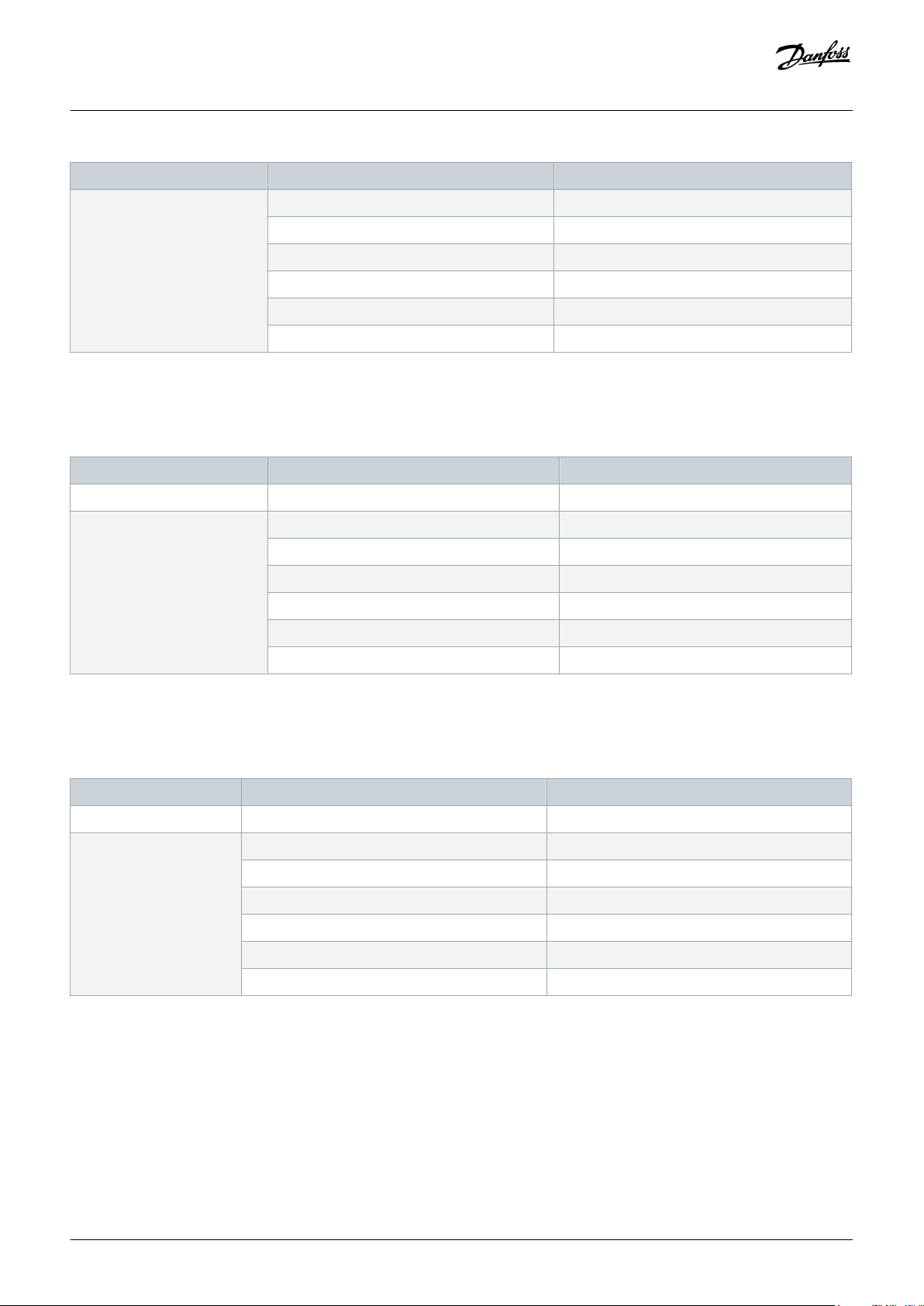
Table 1: Document, Firmware, and Software Versions
Edition Remarks Drive firmware version PROFIBUS firmware version
AQ2895507549010101 First release VLT® Decentral Drive FCD 302, version 7.67 or higher FCD300 Converter, version 2.0x
VLT® Decentral Drive FCD 300, version 1.6x PROFIBUS, version 3.x/4.x
VLT® Decentral Drive FCM 300, version 3.2x PROFIBUS, version 2.x/4.x
Introduction
1.4 Product Overview
1.4.1 Intended Use
This manual relates to the VLT® FCD 300 PROFIBUS Converter MCA 117.
The VLT® FCD 300 PROFIBUS Converter MCA 117 is intended for replacing a VLT® Decentral Drive FCD 300 or a VLT® Decentral Drive
FCM 300 with a VLT® Decentral Drive FCD 302 in a PROFIBUS network.
With this PROFIBUS converter option, the FCD 302 reacts as an FCD 300 or an FCM 300 on the PROFIBUS network. Changes to PLC
programming or configuration are normally not necessary.
The FCD 302 identifies itself either as an FCD 300 or an FCM 300 on the PROFIBUS network. A write command to, for example, ramp-up
time in FCD 300 is automatically linked to the corresponding ramp-up time parameter in the VLT® Decentral Drive FCD 302.
NOTICE
Some parameters in the FCD 300 and FCM 300 are not supported in the FCD 302, and some parameters cannot be accessed via
the VLT® FCD 300 PROFIBUS Converter MCA 117. Refer to 5 Parameter Mapping Lists for more information. If a write request is
attempted to a parameter selection which is not supported, the drive discards the value and issues a positive reply. Only
parameters and functions described in this manual are supported.
NOTICE
The replacement drive must match the power size or be bigger than the replaced FCD 300 or FCM 300. Make sure that the
brake chopper matches the new drive. Make sure that the new drive meets the local regulations concerning the Machinery
Directive, pre-fuses, and other appropriate regulations.
NOTICE
Observe local rules and regulations when replacing a drive in an existing installation.
1.4.2 Hardware
• The VLT® FCD 300 PROFIBUS Converter MCA 117 supports VLT® Decentral Drive FCD 302 only.
• There is no support for PROFIBUS FMS networks.
6 | Danfoss A/S © 2019.11
AQ289550754901en-000101 / 130R0890
Page 7

Operating Guide | VLT® FCD 300 PROFIBUS Converter MCA 117
Introduction
1.4.3 Performance
• The VLT® Decentral Drive FCD 302 reacts faster on most commands as the VLT® Decentral Drive FCD 300/FCM 300, which can
influence the applications. When replacing a VLT® Decentral Drive FCD 300/FCM 300 with the VLT® FCD 300 PROFIBUS Converter
MCA 117, the installer must ensure that the functionality is maintained. Due to the different timing, it may be necessary to
reprogram the controller, where signals from the drives react faster.
• The motor control algorithm of the VLT® Decentral Drive FCD 302 results in a better motor performance compared to FCD 300/FCM
300.
NOTICE
FACTORY SETTING OF PARAMETERS
After initialization of the FCD 302, most parameters are set to match the factory settings of the FCD 300/FCM 300 parameters.
NOTICE
LINKED SETUPS
To synchronize changes made with a running motor, ensure that setups are linked. Link the setups in parameter 0-12 This Setup
Linked to.
Danfoss A/S © 2019.11
AQ289550754901en-000101 / 130R0890| 7
Page 8
Operating Guide | VLT® FCD 300 PROFIBUS Converter MCA 117
2 Safety
2.1 Safety Symbols
The following symbols are used in this manual:
DANGER
Indicates a hazardous situation which, if not avoided, will result in death or serious injury.
WARNING
Indicates a hazardous situation which, if not avoided, could result in death or serious injury.
CAUTION
Indicates a hazardous situation which, if not avoided, could result in minor or moderate injury.
Safety
NOTICE
Indicates information considered important, but not hazard-related (for example, messages relating to property damage).
2.2 Qualified Personnel
Correct and reliable transport, storage, installation, operation, and maintenance are required for the trouble-free and safe operation of
the drive. Only qualified personnel are allowed to install and operate this equipment.
Qualified personnel are defined as trained staff, who are authorized to install, commission, and maintain equipment, systems, and
circuits in accordance with pertinent laws and regulations. Also, the qualified personnel must be familiar with the instructions and
safety measures described in this manual.
2.3 Safety Precautions
WARNING
HIGH VOLTAGE
AC drives contain high voltage when connected to AC mains input, DC supply, or load sharing. Failure to perform installation,
start-up, and maintenance by qualified personnel can result in death or serious injury.
Only qualified personnel must perform installation, start-up, and maintenance.
-
8 | Danfoss A/S © 2019.11
AQ289550754901en-000101 / 130R0890
Page 9

Operating Guide | VLT® FCD 300 PROFIBUS Converter MCA 117
WARNING
UNINTENDED START
When the drive is connected to the AC mains, the motor may start at any time, causing risk of death, serious injury, and
equipment or property damage. The motor may start by activation of an external switch, a fieldbus command, an input
reference signal from the LCP or LOP, via remote operation using MCT 10 Set-up software, or after a cleared fault condition.
Press [Off] on the LCP before programming parameters.
-
Disconnect the drive from the mains whenever personal safety considerations make it necessary to avoid unintended
-
motor start.
Check that the drive, motor, and any driven equipment are in operational readiness.
-
WARNING
DISCHARGE TIME
The drive contains DC-link capacitors, which can remain charged even when the drive is not powered. High voltage can be
present even when the warning indicator lights are off.
Failure to wait the specified time after power has been removed before performing service or repair work could result in death
or serious injury.
Stop the motor.
-
Disconnect AC mains, permanent magnet type motors, and remote DC-link supplies, including battery back-ups, UPS, and
-
DC-link connections to other drives.
Wait for the capacitors to discharge fully. The time for full discharge of the capacitors is minimum 4 minutes for VLT®
-
Decentral Drive FCD 302, 400 V AC, 0.37–3.0 kW (0.5–4.0 hp).
Before performing any service or repair work, use an appropriate voltage measuring device to make sure that the capacitors
-
are fully discharged.
Safety
WARNING
LEAKAGE CURRENT HAZARD
Leakage currents exceed 3.5 mA. Failure to ground the drive properly can result in death or serious injury.
Ensure the correct grounding of the equipment by a certified electrical installer.
-
WARNING
ROTATING SHAFTS
Contact with rotating shafts and electrical equipment can result in death or serious injury.
Ensure that only trained and qualified personnel perform installation, start-up, and maintenance.
-
Ensure that electrical work conforms to national and local electrical codes.
-
Follow the procedures in this guide.
-
Danfoss A/S © 2019.11
AQ289550754901en-000101 / 130R0890| 9
Page 10

Operating Guide | VLT® FCD 300 PROFIBUS Converter MCA 117
WARNING
UNINTENDED MOTOR ROTATION WINDMILLING
Unintended rotation of permanent magnet motors creates voltage and can charge the unit, resulting in death, serious injury, or
equipment damage.
Ensure that permanent magnet motors are blocked to prevent unintended rotation.
-
CAUTION
INTERNAL FAILURE HAZARD
An internal failure in the drive can result in serious injury when the drive is not properly closed.
Ensure that all safety covers are in place and securely fastened before applying power.
-
Safety
10 | Danfoss A/S © 2019.11
AQ289550754901en-000101 / 130R0890
Page 11

Operating Guide | VLT® FCD 300 PROFIBUS Converter MCA 117
Installation
3 Installation
3.1 Introduction to Installation
The VLT® FCD 300 PROFIBUS Converter MCA 117 changes the functionality of a VLT® Decentral Drive FCD 302 so that it can be used as a
spare part for a VLT® Decentral Drive FCD 300 or a VLT® DriveMotor FCM 300.
A VLT® Decentral Drive FCD 302 (0.37–2.2 kW (0.5–3.0 hp)) with flat bracket and adapter brackets (order number 134B6775) can be
mounted using the same drilling holes as for the FCD 300.
For a 3.0 kW (4.0 hp) FCD 302, mounting with adapter brackets is not possible. Thus, new holes must be drilled to mount the drive.
The FCD 302 cannot be used as a direct replacement of the VLT® Decentral Drive FCM 300 electronic part. For reuse of the existing
electric motor, a terminal box has to be fitted to the motor, and a motor cable has to be used as connection between the motor and
the FCD 302. Observe local regulations when changing the installation.
Initial power-up
The VLT® FCD 300 PROFIBUS Converter MCA 117sets the parameters of the VLT® Decentral Drive FCD 302 to FCD 300 defaults in 3
cases:
• At first time power up.
• When the drive has been set to initialize via parameter 14-22 Operation Mode.
• When a 3-finger reset is performed from the LCP at power-up.
This gives a short commissioning time and improves the backwards compatibility.
The MCA 117 also changes the default settings of the I/Os of the FCD 302 to match those of the FCD 300.
3.2 Electrical Installation
For electrical installation, local regulations might require further updates. This could be the case where the installation must be
updated to fulfill newer standards when machines are updated, or if local regulations have changed since the original decentral drives
were installed.
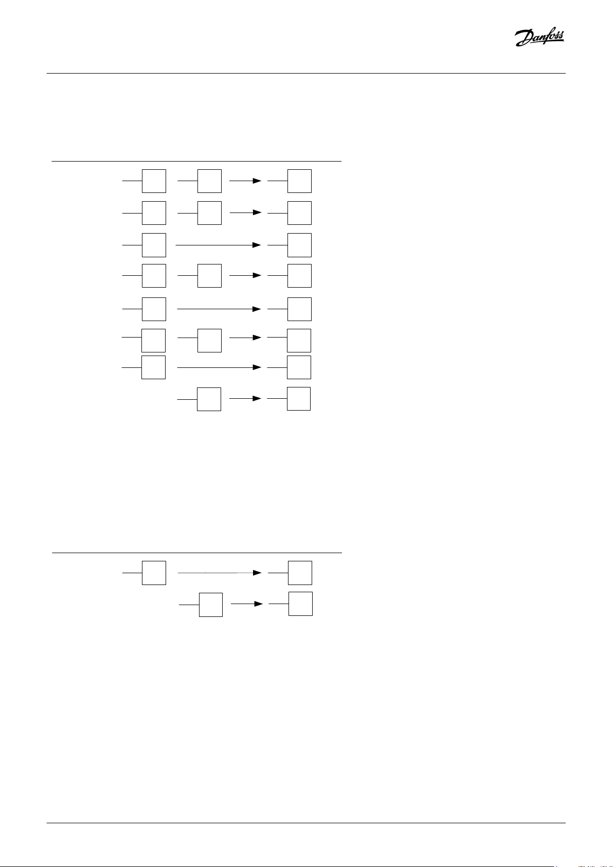
The following sections contain illustrations showing the old terminal number and their equivalents in the new drive. If a box in a
drawing is empty, there is no equivalent in the VLT® Decentral Drive FCD 302. In most cases, it is possible to program the FCD 302 to
deliver the same function on 1 of the terminals. If there are no boxes at all in an illustration, the drive has no terminal. For example, the
VLT® DriveMotor FCM 300 has a limited number of I/Os compared to the FCD 300.
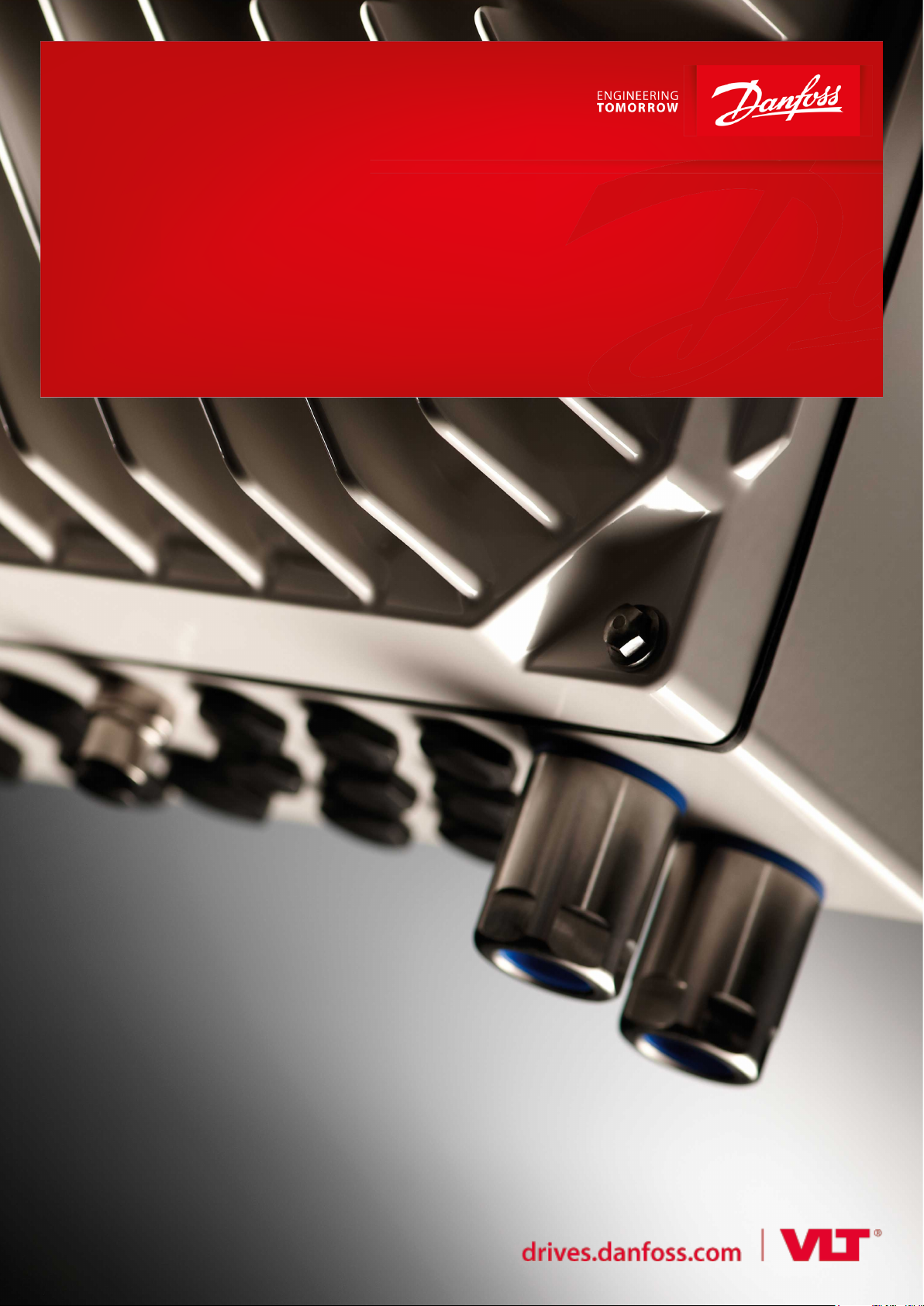
3.2.1 Supply and Motor Terminals
Power cable terminals are 1:1 compatible between VLT® Decentral Drive FCD 300/VLT® DriveMotor FCM 300 and the VLT® Decentral
Drive FCD 302. If shielded cables are used, ensure that the shield is mounted as stated in the VLT® Decentral Drive FCD 302 Operating
Guide.
Danfoss A/S © 2019.11
AQ289550754901en-000101 / 130R0890| 11
Page 12
FCD 300
FCD 302
PE
L1
(91)
L2
(92)
L3
(93)
PE
(95)
L1
(91)
L2
(92)
L3
(93)
POWER
input
FCM 300
PE
L1
L2
L3
e30bh597.10
PE
PE
(99)
U
(96)
V
(97)
W
(98)
U
(96)
V
(97)
W
(98)
Motor
connector
FCD 300
FCD 302
FCM 300
e30bh604.10
122
123
122
123
Mechanical brake
FCD 300
FCD 302
FCM 300
e30bh603.10
Operating Guide | VLT® FCD 300 PROFIBUS Converter MCA 117
Installation
Illustration 1: Power Cable Connections
Motor terminals are 1:1 compatible between FCD 300 and FCD 302. If shielded cables are used, ensure that the shield is mounted as
stated in the VLT® Decentral Drive FCD 302 Operating Guide.
Illustration 2: Motor Cable Connections
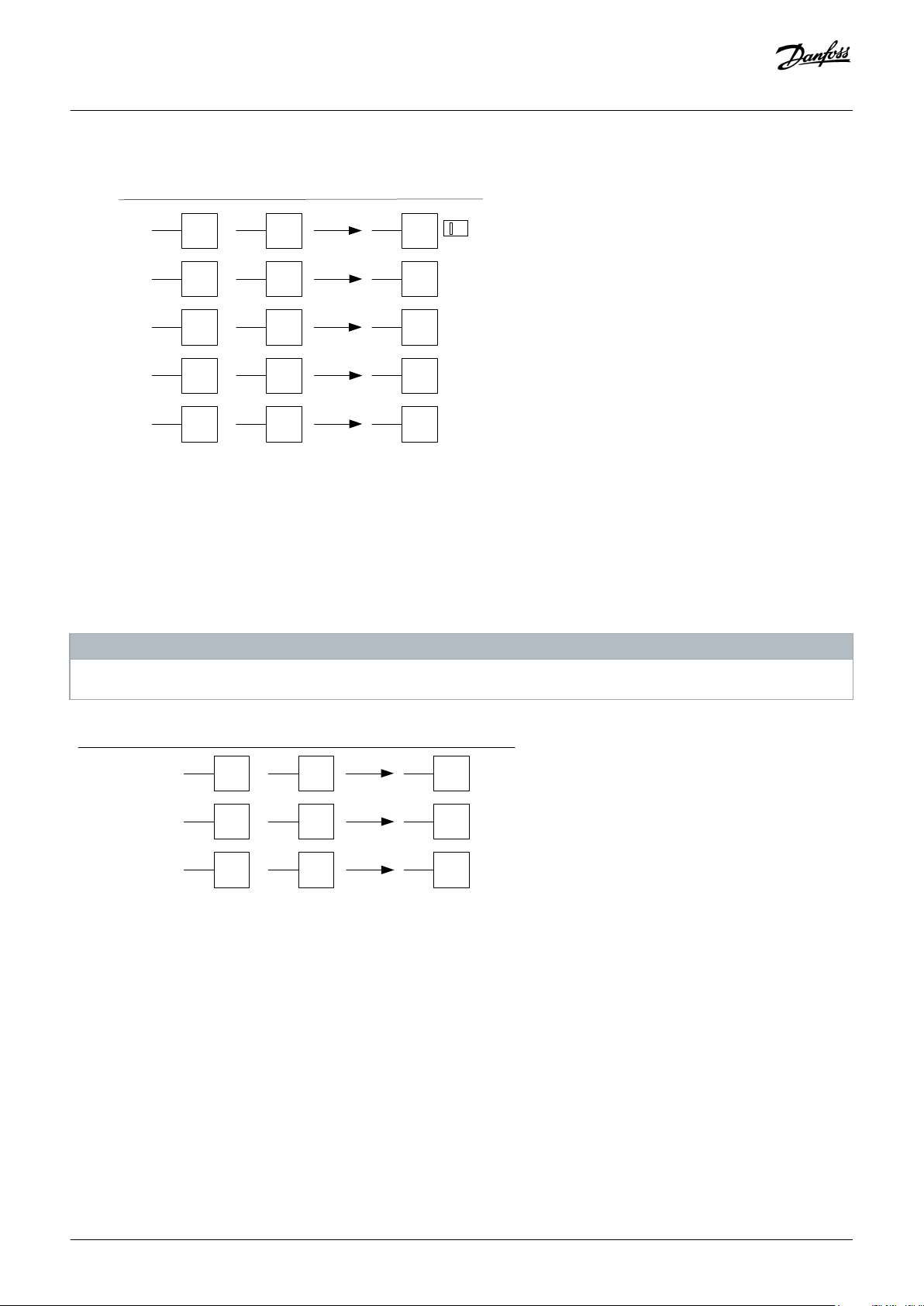
Mechanical brake cable terminals are 1:1 compatible between the FCD 300 EB versions and the FCD 302 with brake chopper and
mechanical brake supply. If shielded cables are used, ensure that the shield is mounted as stated in the VLT® Decentral Drive FCD 302
Operating Guide. To enable this functionality, the VLT® FCD 300 PROFIBUS Converter MCA 117 sets parameter 5-40 [1] Function Relay to
[32] Mech Brake Ctrl. In the FCD 302, it is not possible to enable mechanical brake control and use relay 2 for another purpose.
Illustration 3: Mechanical Brake Connection
12 | Danfoss A/S © 2019.11
AQ289550754901en-000101 / 130R0890
Page 13
81 -
82 +
81 -
82 +
Brake
Resistor
FCD 300
FCD 302
FCM 300
e30bh599.10
e30bh605.10
31A
31B
50
54
FCD300
FCD302FCM300
1 2
ON
S202
A54 OFF
36
(+)
36
(+)
35
(-)
35
(-)
36
(+)
36
(+)
35
(-)
35
(-)
External
24 V DC
back-up
FCD 300
FCD 302FCM 300
e30bh602.10
Operating Guide | VLT® FCD 300 PROFIBUS Converter MCA 117
Installation
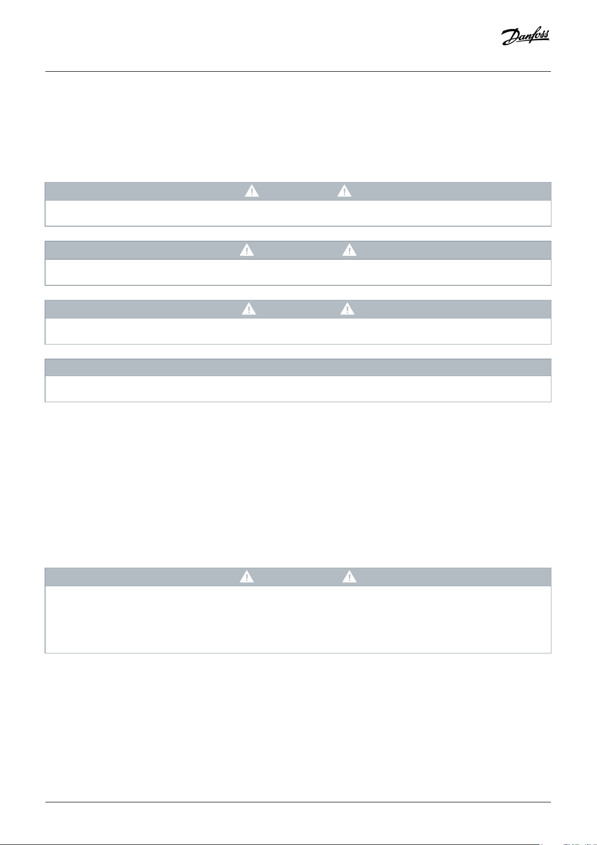
Brake resistor cable terminals are 1:1 compatible between the FCD 300 EB versions and the FCD 302. If shielded cables are used, ensure
that the shield is mounted as stated in the VLT® Decentral Drive FCD 302 Operating Guide.
Illustration 4: Brake Resistor Cable Connections
The FCD 300 has dedicated connectors 31A and 31B for connection of the motor thermistors. The FCD 302 with MCA 117 installed uses
AI54 as motor thermistor connector. The FCD 302 can also use 1 of the digital inputs as thermistor source, but if multiple sensors are
connected in series, it might cause false alarms/warnings. The motor thermistor configuration is done via parameter 1-90 Motor Thermal
Protection and parameter 1-93 Thermistor Resource.
Illustration 5: Motor Thermistor Cable Connection
The 24 V external supply cable terminals are 1:1 compatible between FCD 300 EB versions and the FCD 302. The FCD 302 may draw a
higher current from the 24 V supply. The FCD 300 has a power consumption of 12 W, where the FCD 302 consumes up to 50 W. The
consumption depends on the configuration of the I/O modules and the sensors connected to the drive.
Illustration 6: External 24 V Cable Connection
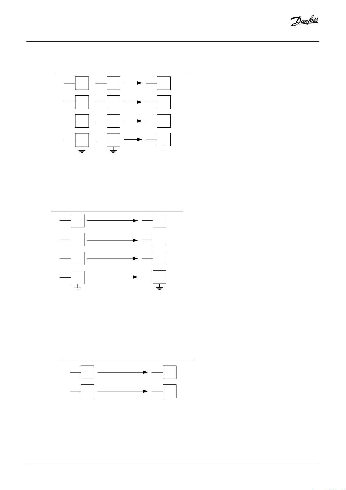
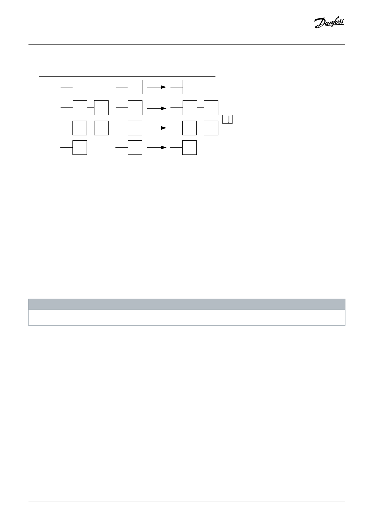
3.2.2 Control Signal Connectors
Digital input cable connection
Digital input terminals are 1:1 compatible between the VLT® Decentral Drive FCD 300 and the VLT® Decentral Drive FCD 302. If shielded
cable is used, ensure that the shield is mounted as stated in the VLT® Decentral Drive FCD 302 Operating Guide.
The FCD 300 reads the digital inputs every 12 ms whereas the FCD 302 reads the digital inputs every 1 ms.
Danfoss A/S © 2019.11
AQ289550754901en-000101 / 130R0890| 13
Page 14
20
27
12
18
19
29
33
20
27
12-
13
18
19
29
33
FCD 300
FCD 302
Digital in
FCM 300
6
4
5
8
3
e30bh600.11
46
Digital out
FCD 300
FCD 302
FCM 300
9
e30bh601.10
Operating Guide | VLT® FCD 300 PROFIBUS Converter MCA 117
Installation
The digital inputs of the FCD 300 are converted fully to the I/Os of the FCD 302. Terminal 3 of the VLT® DriveMotor FCM 300 is not
converted to a corresponding terminal in FCD 302. To support terminal 3 in FCM 300, configure the FCD 302 manually.
Illustration 7: Digital Input Cable Connections
Digital output cable connections
The FCD 300 has 1 dedicated digital output, which is terminal 46. This terminal is not converted to an existing FCD 302 output.
In FCM 300, terminal 9 could be used as either analog or digital output. To obtain the same functionality in FCD 302, configure an
analog or digital output manually.
Illustration 8: Digital Output Cable Connections
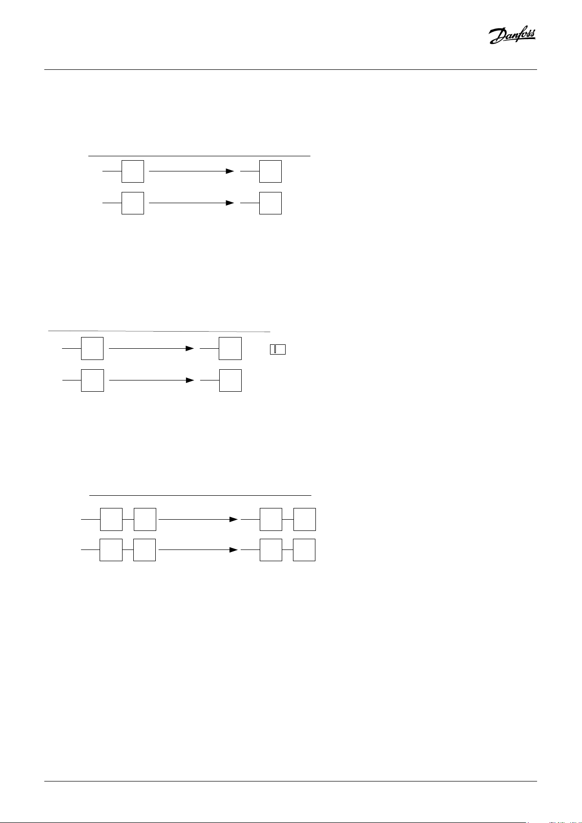
Analog I/O cable connections
The analog I/Os of the FCD 302 can be configured to cover most use cases. The default conversion from FCD 300 has a limitation as
there is no input 60 in the FCD 302. If analog input 54 in the FCD 302 is not used for motor thermistor, this input can be configured to
provide the functionality of output 60 in the FCD 300.
14 | Danfoss A/S © 2019.11
AQ289550754901en-000101 / 130R0890
Page 15
e30bh598.10
53
50
10 V
42
42
53
60
50
10 V
55
Gnd
55
Gnd
FCD300
FCD302
Analog
I/O
2
9
7
8
1
FCM300
1 2
ON
S202
A53 switch
OFF = 0‐10V
01
C
02
NO
03
NC
01
C
02
NO
03
NC
FCD 300
FCD 302
Relay
1
x102
2
x102
3
x102
FCM 300
e30bh607.10
Operating Guide | VLT® FCD 300 PROFIBUS Converter MCA 117
Installation
Illustration 9: Analog I/O Cable Connections
The 0–10 V analog input 53 of the FCD 300 is converted into the FCD 302 analog input 53. The analog input 53 of the FCD 302 can be
set to 0–10 V or 0–20 mA via switch S201. From factory, the switch is set in OFF position, which sets the analog input to 0–10 V.
Relay cable connections
The relays of the FCD 302 are compatible to the relays in FCD 300.
NOTICE
The relay in FCM 300 is rated to a resistive load of 5 A, 250 V AC, whereas the relay in FCD 302 is rated to a load of 2 A, 240 V AC.
Illustration 10: Relay Cable Connections
PROFIBUS cable connections
The PROFIBUS terminals of the FCD 300/FCM 300 are all converted to the PROFIBUS terminals of the FCD 302. The compensation coils
activated by the switches S101 to S104 of the FCD 300 are not needed in the FCD 302 PROFIBUS interface. The Termination of the
PROFIBUS line is done via the PROFIBUS termination switch.
Danfoss A/S © 2019.11
AQ289550754901en-000101 / 130R0890| 15
Page 16
e30bh606.10
67
68
68
69 69
70
67
68
68
69 69
66
FCD300
FCD302
PROFIBUS
3
x100
1
x100
2
x100
4
x100
FCM300
1 2 3
ON
PROFIBUS
TERM.
Operating Guide | VLT® FCD 300 PROFIBUS Converter MCA 117
Installation
Illustration 11: PROFIBUS Cable Connections
3.2.3 EMC Precautions
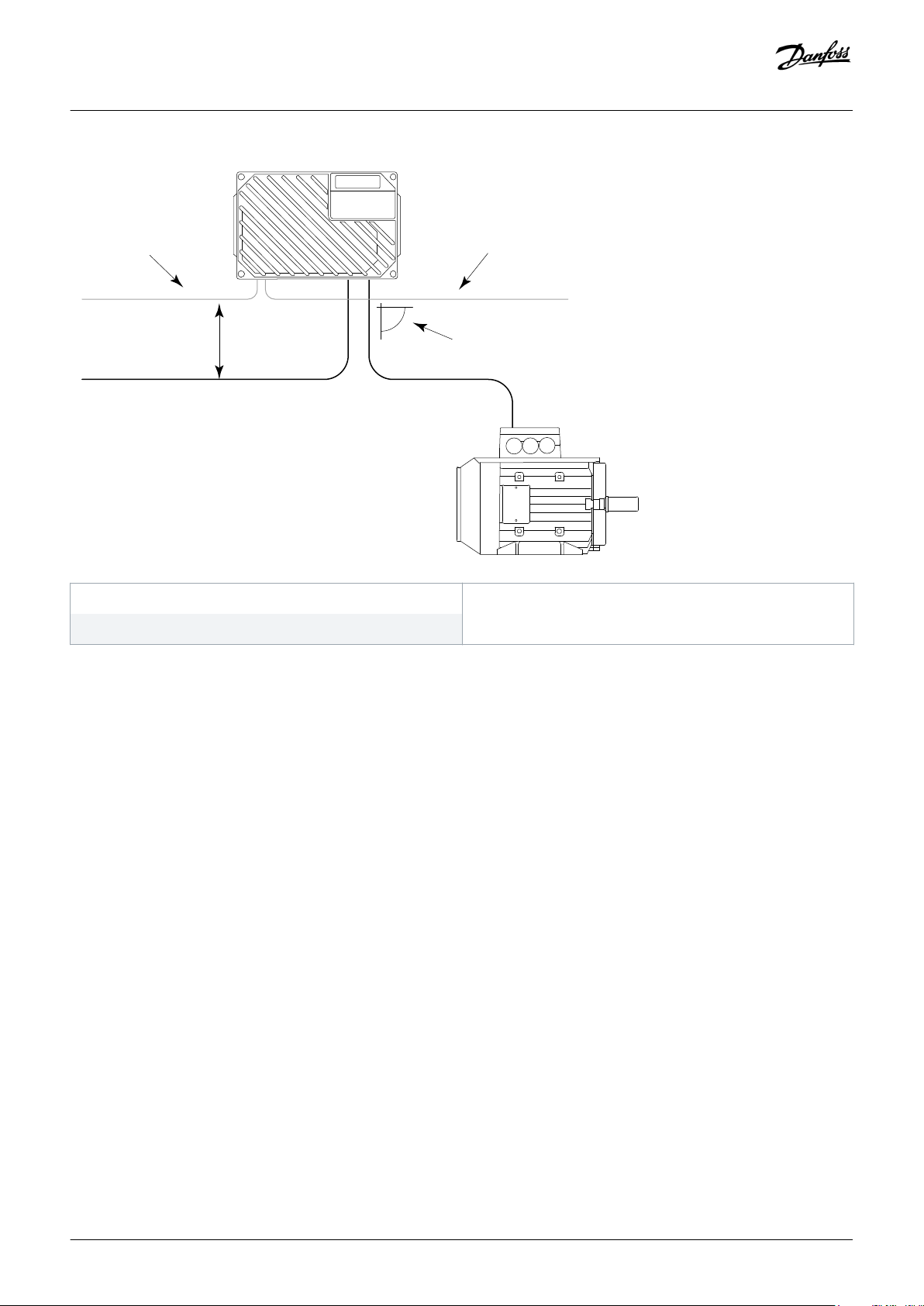
To achieve interference-free operation of the PROFIBUS, install the VLT® Decentral Drive FCD 302 and the cables as described in the
VLT® Decentral Drive FCD 302 Design Guide: When routing the PROFIBUS cable:
• maintain high distance (minimum 200 mm (8 in)) between the PROFIBUS communication cable and the motor and brake resistor
cables to avoid coupling of high-frequency noise from one cable to another.
• ensure that, when crossing is unavoidable, the PROFIBUS cable crosses the motor and brake resistor cables at an angle of 90° .
For installation on machines where the FCD 302 has poor electrical contact to the machine due to paint or high ohmic surface, a special
stainless steel plug and bracket exist. The order number is 175N2598.
This plug can be mounted in 1 of the unused cable entry holes and the supplied bracket has to be mounted to the plug and to the
metal construction of the machine. This ensures a low ohmic path for high-frequency noise that otherwise would have been added to
the shield of the PROFIBUS cable, causing disturbance of the communication.
NOTICE
Observe relevant national and local regulations, for example, regarding protective-earth connection.
16 | Danfoss A/S © 2019.11
AQ289550754901en-000101 / 130R0890
Page 17
2
1
3
90°
e30bh659.10
1
Operating Guide | VLT® FCD 300 PROFIBUS Converter MCA 117
Installation
1 PROFIBUS cable
3 ≥200 mm (≥7.9 in)
Illustration 12: EMC-correct Installation
2 90° intersection
Danfoss A/S © 2019.11
AQ289550754901en-000101 / 130R0890| 17
Page 18

Operating Guide | VLT® FCD 300 PROFIBUS Converter MCA 117
Configuring the System
4 Configuring the System
4.1 Preparing for Configuration
Context:
All PROFIBUS stations connected to the same bus network must have a unique station address.
Prerequisites:
Before replacing an FCD 300 or FCM 300 by a VLT® Decentral Drive FCD 302 with VLT® FCD 300 PROFIBUS Converter MCA 117,
configure the station address in the FCD 302. Also, check that the FCD 302 detects which type of drive it has to replace.
Procedure
1. Set the PROFIBUS address of the VLT® Decentral Drive FCD 302 to the same address as the drive that has to be replaced.
2. Set parameter 8-02 Control Word Source to [3] Option A.
3. Cycle power (400 V AC and 24 V DC back-up if applied) to the FCD 302.
The MCA 117 probes for the different FCD300/FCM300 Ident numbers. While probing, the drive flashes the ST/MS LED (see
4.5 LED Behavior). When the matching Ident number used by the master is detected, the VLT® Decentral Drive FCD 302
locks the ident number to the option, and sets the parameters of the FCD 302 to match the functionality of the old drive.
The master/PLC now recognizes the FCD 302 as an FCD 300 or FCM 300.
4.2 PROFIBUS Address Set via Hardware Switches
WARNING
SHOCK HAZARD
Working with the hardware switches while the power supply is still on may cause personal injuries.
Switch off the power supply before changing the hardware switches.
-
NOTICE
The address change comes into effect at the next power-up and can be read in parameter 9-18 Node Address.
18 | Danfoss A/S © 2019.11
AQ289550754901en-000101 / 130R0890
Page 19
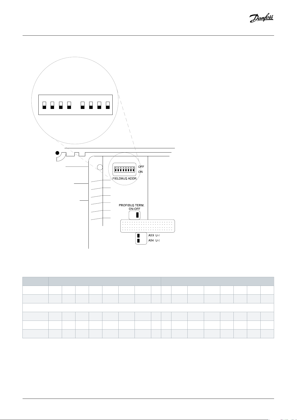
e30bh608.10
1
2 3 4 5 6 7 8
8 7 6 5 4 3 2 1
ON
OFF
Operating Guide | VLT® FCD 300 PROFIBUS Converter MCA 117
Configuring the System
Illustration 13: Setting the PROFIBUS Address via Hardware Switches
Table 2: Hardware Switch Settings
VLT® Decentral Drive FCD 300 VLT® Decentral Drive FCD 302
Switch 1 2 3 4 5 6 7 8 8 7 6 5 4 3 2 1
Address +1 +2 +4 +8 +16 +32 +64 – – +64 +32 +16 +8 +4 +2 +1
Example:
1 1 0 0 0 0 0 0 – – 0 0 0 0 0 0 1
35 1 1 0 0 0 1 0 – – 0 1 0 0 0 1 1
82 0 1 0 0 1 0 1 – – 1 0 1 0 0 1 0
Danfoss A/S © 2019.11
AQ289550754901en-000101 / 130R0890| 19
Page 20
BUS
ON
ALARM
ST/MS LA2/NS2
WARNING
LA1/NS1
e30bh741.10
Operating Guide | VLT® FCD 300 PROFIBUS Converter MCA 117
Configuring the System
4.3 PROFIBUS Address Set via Parameter or SSA Command
If all hardware switches are set to ON or OFF (factory switch setting), the PROFIBUS address can be set via parameter 9-18 Node Address
or the PROFIBUS SSA command. The address becomes valid after the next power cycle.
4.4 Commissioning
Prerequisites:
The station address of the VLT® Decentral Drive FCD 302 must be the same as for VLT® Decentral Drive FCD 300.
Procedure
1. Cycle power to the FCD 302.
The master/PLC now recognizes FCD 302 as an FCD 300.
Example:
A solid green NS LED on the VLT® FCD 300 PROFIBUS Converter MCA 117 indicates that communication between master and slave is
established.
If the NS LED flashes, the master/PLC has not recognized the FCD 302.
For more information, refer to 6.1 Troubleshooting Hints.
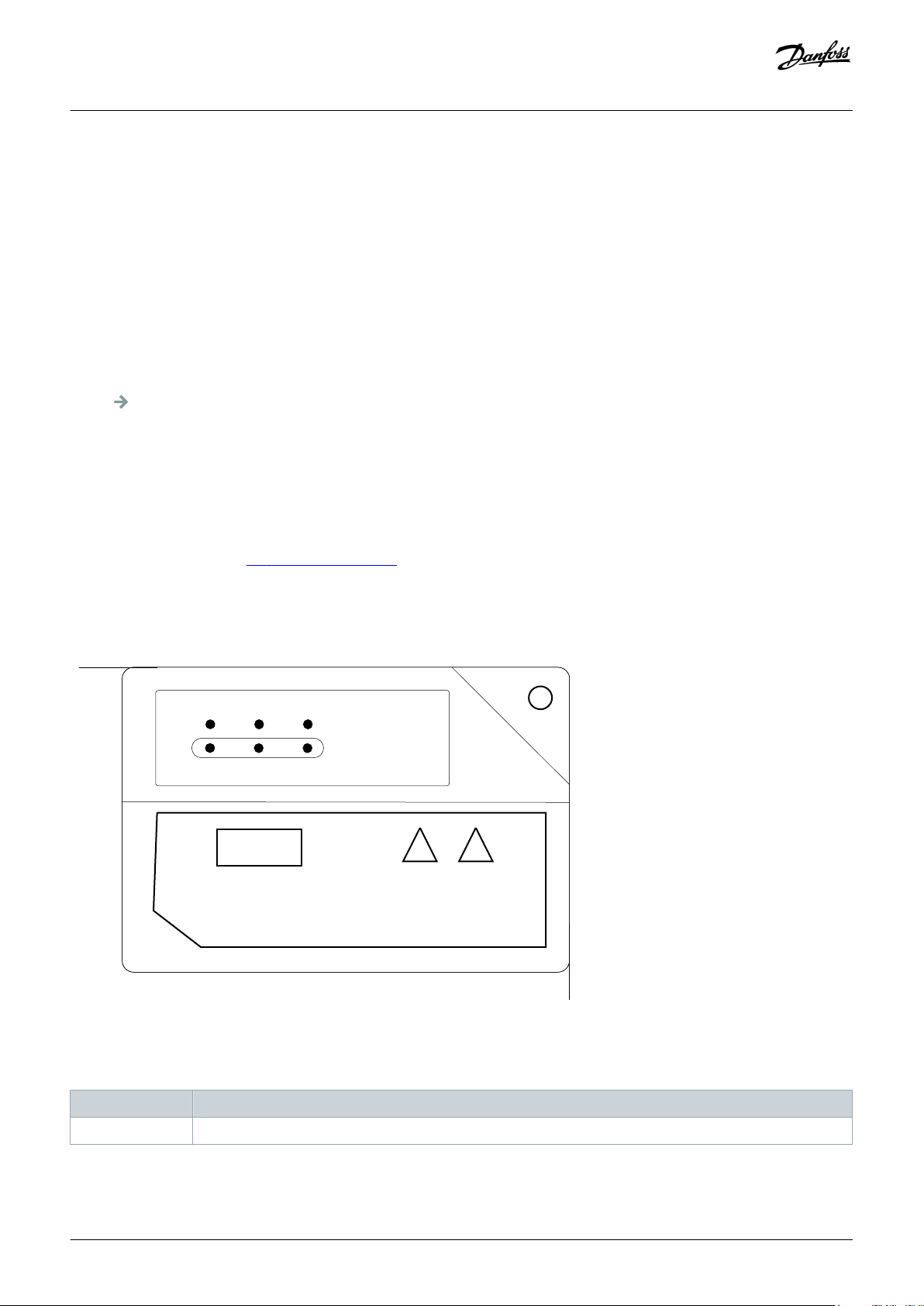
4.5 LED Behavior
Illustration 14: Overview of LEDs
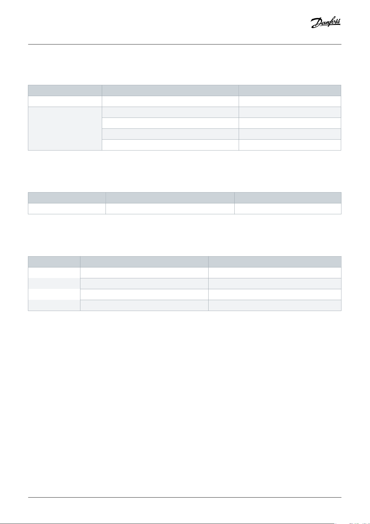
Table 3: Bicolored LEDs
LED label Description
LA1/NS1 Network status
20 | Danfoss A/S © 2019.11
AQ289550754901en-000101 / 130R0890
Page 21
Operating Guide | VLT® FCD 300 PROFIBUS Converter MCA 117
Configuring the System
LED label Description
ST/MS Module status (DP-V1 communication and Ident number detection)
LA2/NS2 Not used
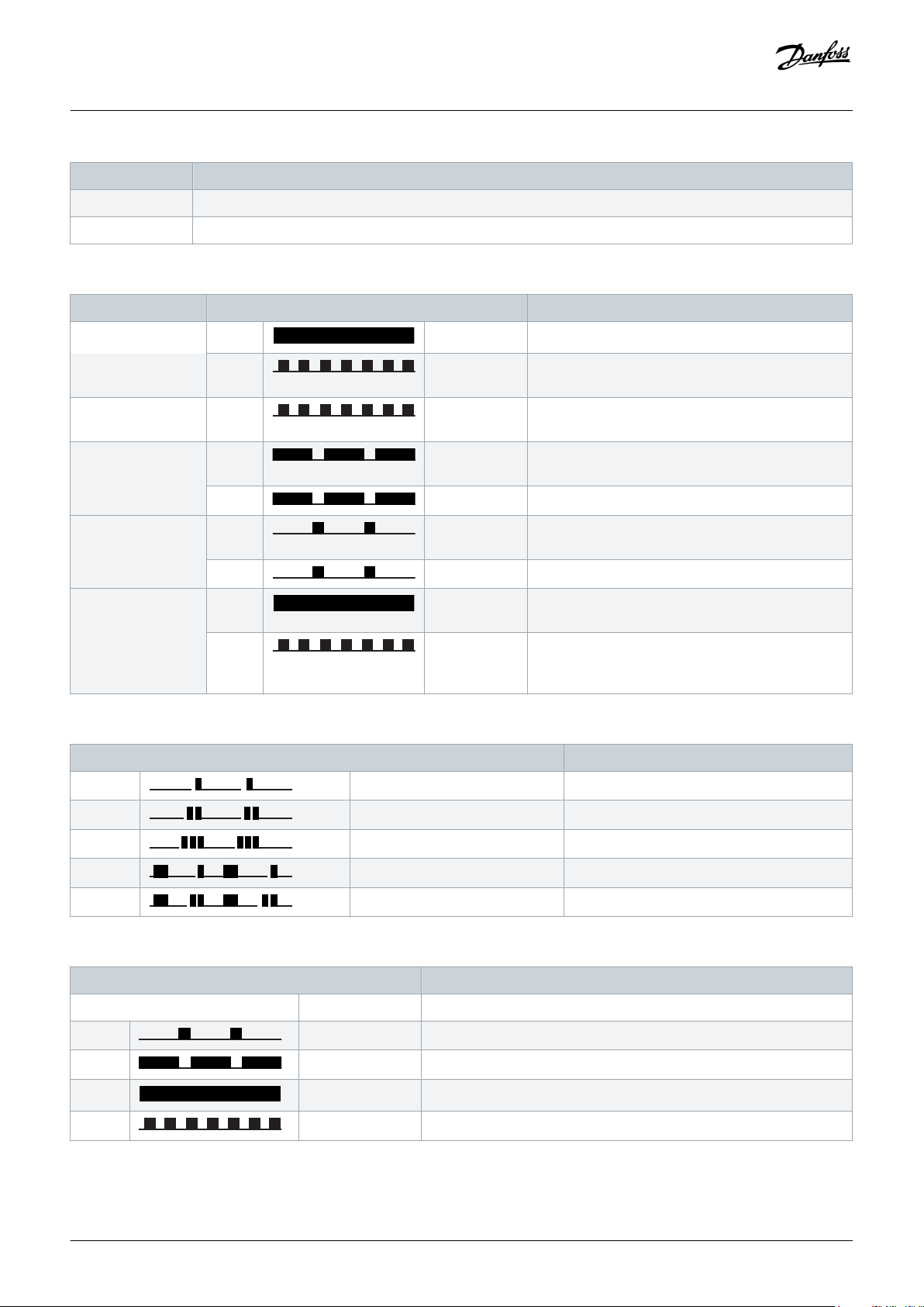
Table 4: Net Status, ST/MS
State LED Description
Power on Red: Solid red The option is defect. Contact Danfoss.
Green: Flashing
The option is OK.
green
Baud rate search Green: Flashing
green
Wait parameterizing Green: Long green
flash
Searching for the baud rate. Check the connection
to the master if the option stays in this state.
Baud rate found - waiting for parameters from the
master.
Red: Long red flash Wrong parameters from the master.
Wait configuration Green: Short green
flash
Parameters from master OK - waiting for configuration data.
Red: Short red flash Wrong configuration data from the master.
Data exchange Green: Solid green Data exchange between the master and the FCD 302
is active.
Red: Flashing red Clear state. Warning 34, Fieldbus Fault is active and a
bus reaction in parameter 8-04 Control Word Timeout
Function is executed.
Table 5: Module Status (ST/MS LED while Detecting Ident Number)
LED description Description
Green One short flash Testing for FCD 300, 12 MB version
Green Two short flashes Testing for FCD 300, 3 MB version
Green Three short flashes Testing for FCD 302
Green One long, one short flash Testing for FCM 300, 3 MB version
Green One long, 2 short flashes Testing for FCM 300, 12 MB version
Table 6: Module Status (DP-V1 Communication)
Description
No light Off No PROFIBUS DP-V1 communication is active.
Green: Short green flash DP-V1 communication from a Master Class 1 (PLC) is active.
Green: Long green flash DP-V1 communication from a Master Class 2 (MCT 10, FDT) is active.
Green: Solid green DP-V1 communication from a Master Class 1 and 2 is active.
Red: Flashing red Internal error.
Danfoss A/S © 2019.11
AQ289550754901en-000101 / 130R0890| 21
Page 22

Operating Guide | VLT® FCD 300 PROFIBUS Converter MCA 117
Configuring the System
NOTICE
The LED flash patterns of the VLT® FCD 300 PROFIBUS Converter MCA 117 are not compatible with the patterns of the FCD
300/FCM 300 PROFIBUS LEDs.
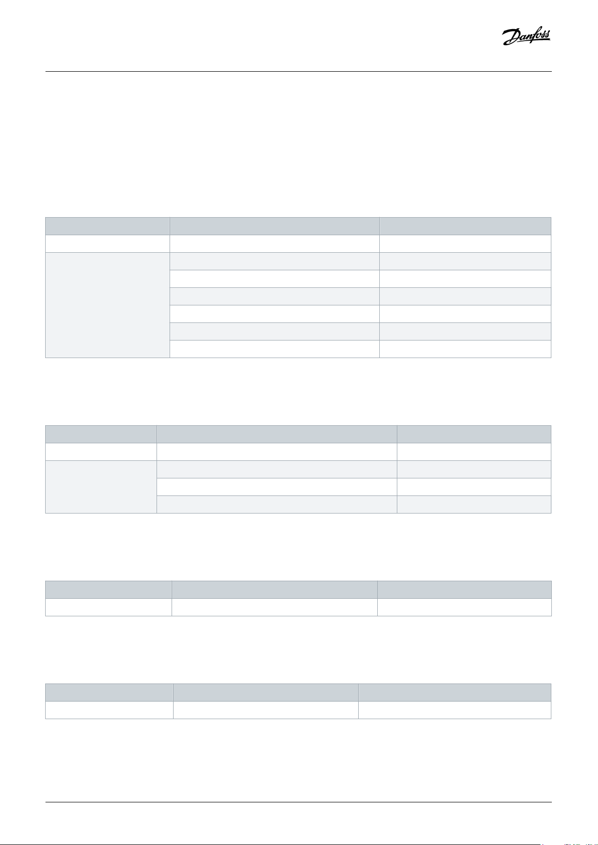
4.6 Factory Settings
The VLT® FCD 300 PROFIBUS Converter MCA 117 is delivered from factory with the optimal settings to replace a VLT® Decentral Drive
FCD 300. If the VLT® FCD 300 PROFIBUS Converter MCA 117 is moved from one application to another, it is recommend to initialize the
drive. This initialization activates the factory settings and re-invoke of the Ident number detection. If the drive has been delivered from
factory with the option installed, initialization can be skipped.
Do the initialization via:
• Parameter 14-22 Operation Mode, or
• Three-finger reset by removing power to the drive, pressing [Status], [Main Menu], and [OK], and applying 400 V AC or 24 V DC
back-up power to the drive.
The MCA 117 sets the parameters of the FCD 302 so that the FCD 302/MCA 117 emulate the FCD 300 in the best way.
The parameters of the VLT® Decentral Drive FCD 302 are set to factory values and some FCD 302 parameters are set to values that
match the initial values of VLT® Decentral Drive FCD 300.
Factory copy via the FCD 300 parameter 006 Setup Copy is supported and initializes the FCD 302 and sets it to the FCD 300 default
settings.
Table 7: Parameters Set During Initialization
Parameter Initialization setting
Parameter 0-02 Motor Speed Unit [Hz]
Parameter 1-51 Min Speed Normal Magnetizing [RPM] 30 RPM
Parameter 1-52 Min Speed Normal magnetising [Hz] 1.0 Hz
Parameter 1-64 Resonance Damping 0
Paramter 1-81 Min Speed for Function at Stop [RPM] 3 RPM
Parameter 1-82 Min Speed for Function at Stop [Hz] 0.1 Hz
Parameter 1-93 Thermistor Resource Analog input 54
Parameter 2-10 Brake Function [0] Off
Parameter 2-17 Overvoltage Control [0] Off
Parameter 3-00 Reference Range min – max
Parameter 3-01 Reference/Feedback Unit [1]%
Parameter 3-03 Maximum Reference 50.000
Parameter 3-11 Jog Speed [Hz] 10.0 Hz
Parameter 3-16 Reference Resource 2 [0] No function
Parameter 3-19 Jog Speed [RPM] 300 RPM
Parameter 4-13 Motor Speed High Limit [RPM] 3960 RPM
22 | Danfoss A/S © 2019.11
AQ289550754901en-000101 / 130R0890
Page 23

Operating Guide | VLT® FCD 300 PROFIBUS Converter MCA 117
Parameter Initialization setting
Parameter 4-14 Motor Speed Low Limit [Hz] 132.0 Hz
Parameter 4-16 Torque Limit Motor Mode 355.6
Parameter 4-17 Torque Limit Generator Mode 355.6
Parameter 4-30 Motor Feedback Loss Function [0] Disabled
Parameter 4-32 Motor Feedback Loss Timeout 1.00 s
Parameter 4-53 Warning Speed High 3960
Parameter 4-56 Warning Feedback Low -4000000
Parameter 4-57 Warning Feedback High 4000000
Parameter 5-02 Terminal 29 Mode [1] Output
Parameter 5-10 Terminal 18 Digital Input [8] Start
Parameter 5-11 Terminal 19 Digital Input [10] Reversing
Parameter 5-12 Terminal 27 Digital Input [3] Coast and reset inv
Parameter 5-14 Terminal 32 Digital Input [14] Jog
Configuring the System
Parameter 5-40.0 Function Relay [22] Ready, No Thermal Warning
Parameter 5-40.1 Function Relay [32] Mech Brake Ctrl
Parameter 5-41 On Delay, Relay [23] Remote, Ready, No TW
Parameter 5-51 Term. 29 High Frequency 5000 Hz
Parameter 5-53 Term. 29 High Ref./Feedb. Value 50.000
Parameter 5-56 Term. 33 High Frequency 25000 Hz
Parameter 5-58 Term. 33 High Ref./Feedb. Value 50.000
Parameter 6-10 Terminal 53 Low Voltage 0.00 V
Parameter 6-15 Term. 53 High Ref./Feedb. Value 50.000
Parameter 6-20 Terminal 54 Low Voltage 0.00 V
Parameter 6-22 Terminal 54 Low Current 0.00 V
Parameter 6-25 Terminal 54 High Ref./Feedb. Value 50.000
Parameter 6-50 Terminal 42 Output [103] Motor current
Parameter 7-04 Speed PID Differention Time 0.0
Parameter 7-08 Speed PID Feed Forward Factor 100
Parameter 7-09 Speed PID Error Correction w/Ramp 100000 (max)
Parameter 7-33 Process PID Proportional Gain 0.01
Parameter 8-54 Reversing Select [0] Digital input
Parameter 8-90 Bus Jog 1 Speed 300 RPM
Parameter 8-91 Bus Jog 2 Speed 300 RPM
Parameter 14-03 Overmodulation [0] Off
Parameter 14-11 Mains Voltage at Mains Fault 327
Danfoss A/S © 2019.11
AQ289550754901en-000101 / 130R0890| 23
Page 24

Operating Guide | VLT® FCD 300 PROFIBUS Converter MCA 117
Parameter Initialization setting
Parameter 14-15 Kin. Back-up Trip Recovery Level 1,000.000
Parameter 14-21 Automatic Restart Time 5 s
Parameter 14-32 Current Lim Ctrl, Filter Time 27
Parameter 30-84 Process PID Proportional Gain 0.010
PROFIBUS-specific parameters
Parameter 9-71 PROFIBUS Save Data Values [1] Store All Setups
Configuring the System
24 | Danfoss A/S © 2019.11
AQ289550754901en-000101 / 130R0890
Page 25
Operating Guide | VLT® FCD 300 PROFIBUS Converter MCA 117
5 Parameter Mapping Lists
5.1 FCD 300 Parameter Group 0
5.1.1 Conversion of Parameter 001 Language Select
Table 8: Parameter 001
FCD 300 series FCD 302 series
Parameter 001 Language Select 0-01 Language
Options [0] English [0] English
[1] Deutsch [1] Deutsch
[2] French [2] French
[3] Dansk [3] Dansk
[4] Spanish [4] Spanish
[5] Italian [5] Italian
Parameter Mapping Lists
5.1.2 Conversion of Parameter 002 Operation Site
Table 9: Parameter 002
FCD 300 series FCD 302 series
Parameter 002 Operation Site Not converted
Options [0] Remote –
[1] Local with External Stop –
[2] Local –
5.1.3 Conversion of Parameter 003 Local Reference
Table 10: Parameter 003
FCD 300 series FCD 302 series
Parameter 003 Local Reference Not converted
5.1.4 Conversion of Parameter 004 Active Set-up
Table 11: Parameter 004
FCD 300 series FCD 302 series
Parameter 004 Active Set-up 0-10 Active Set-up
Danfoss A/S © 2019.11
AQ289550754901en-000101 / 130R0890| 25
Page 26
Operating Guide | VLT® FCD 300 PROFIBUS Converter MCA 117
FCD 300 series FCD 302 series
Options [0] Factory Setup [0] Factory Setup
[1] Setup 1 [1] Setup 1
[2] Setup 2 [2] Setup 2
[3] Setup 3 [3] Setup 3
[4] Setup 4 [4] Setup 4
[5] Multi Setup [9] Multi Setup
5.1.5 Conversion of Parameter 005 Edit Setup
Table 12: Parameter 005
FCD 300 series FCD 302 series
Parameter 005 Edit Setup 9-70 Set-up Copy
Options [0] Factory Set-up [0] Factory Set-up
Parameter Mapping Lists
[1] Setup 1 [1] Setup 1
[2] Setup 2 [2] Setup 2
[3] Setup 3 [3] Setup 3
[4] Setup 4 [4] Setup 4
[5] Active Setup [9] Active Setup
5.1.6 Conversion of Parameter 006 Setup Copy
Table 13: Parameter 006
FCD 300 series FCD 302 series
Parameter 006 Setup Copy 0-51 Set-up Copy
Options [0] No Copy [0] No Copy
[1] Copy to 1 from # [9] Copy to ALL from #
[2] Copy to 2 from # [9] Copy to ALL from #
[3] Copy to 3 from # [9] Copy to ALL from #
[4] Copy to 4 from # [9] Copy to ALL from #
[5] Copy to ALL from # [9] Copy to ALL from #
26 | Danfoss A/S © 2019.11
AQ289550754901en-000101 / 130R0890
Page 27
Operating Guide | VLT® FCD 300 PROFIBUS Converter MCA 117
5.1.7 Conversion of Parameter 007 LCP Copy
Table 14: Parameter 007
FCD 300 series FCD 302 series
Parameter 007 LCP Copy 0-50 LCP Copy
Options [0] No copy Not converted
[1] Upload all Param Not converted
[2] Download All Not converted
[3] Download Size Inde Not converted
5.1.8 Conversion of Parameter 008 Frequency Scale
Table 15: Parameter 008
FCD 300 series FCD 302 series
Parameter 008 Frequency Scale Not converted
Parameter Mapping Lists
5.1.9 Conversions of Parameters 009 to 012 Display Line
Table 16: Parameters 009 to 012
FCD 300 series FCD 302 series
Parameter 009 Display Line 0-23 Display Line 2
010 Display Line 0-20 Display Line 1.1
011 Display Line 0-21 Display Line 1.2
012 Display Line 0-22 Display Line 1.3
Danfoss A/S © 2019.11
AQ289550754901en-000101 / 130R0890| 27
Page 28

Operating Guide | VLT® FCD 300 PROFIBUS Converter MCA 117
FCD 300 series FCD 302 series
Options [0] None [0] None
[1] Reference % [1602] Reference %
[2] Reference [Unit] [1601] Reference [Unit]
[3] Feedback [Unit] [1652] Feedback [Unit]
[4] Frequency [Hz] [1613] Frequency [Hz]
[5] Frequency x scale [1609] Custom readout
[6] Motor Current [A] [1614] Motor Current [A]
[7] Torque [1622] Torque [%]
[8] Power [kW] [1610] Power [kW]
[9] Power [HP] [1611] Power [HP]
[10] Output energy [kWh] [1502] kWh counter [kWh]
[11] Motor voltage [V] [1612] Motor voltage [V]
[12] DC link voltage [V] [1630] DC link voltage [V]
Parameter Mapping Lists
[13] Thermal load, motor [%] [1618] Thermal load, motor [%]
[14] Thermal load, VLT® [%] [1635] Inverter thermal [%]
[15] Running hours [hours] [1501] Running hours [hours]
[16] Digital input [1660] Digital input
[17] Analog input 53 [V] [1662] Analog input 53 [V]
[19] Analog input 60 [mA] [1662] Analog input 53 [mA]
[20] Pulse reference [Hz] [1651] Pulse reference [Hz]
[21] Ext. reference [%] [1650] Ext. reference [%]
[22] Status word [hex] [1603] Status word [hex]
[24] Brake effect/sec [kW] [1632] Brake effect/sec [kW]
[25] Heat sink temp. [1634] Heat sink temp.
[26] Alarm word [hex] –
[27] Control word [hex] [1600] Control word [hex]
[28] Warning word 1 [hex] –
[29] Warning word 2 [hex] –
[30] Com. Option warning [hex] [953] Com. Option warning [hex]
[31] RPM [min] [1617] Speed RPM [min]
28 | Danfoss A/S © 2019.11
[32] RPM x scaling [min] [1609] Custom readout
AQ289550754901en-000101 / 130R0890
Page 29

Operating Guide | VLT® FCD 300 PROFIBUS Converter MCA 117
5.1.10 Conversion of Parameter 013 Local Ctrl./config
Table 17: Parameter 013
FCD 300 series FCD 302 series
Parameter 013 Local Ctrl./config Not converted
5.1.11 Conversion of Parameter 014 Local Stop Key
Table 18: Parameter 014
FCD 300 series FCD 302 series
Parameter 014 Local Stop Key 0-41 [Off] Key on LCP
Options [0] Disable [0] Disable
[1] Enable [1] Enable
– [2] Password
Parameter Mapping Lists
5.1.12 Conversion of Parameter 015 Local Jogging
Table 19: Parameter 015
FCD 300 series FCD 302 series
Parameter 015 Local Jogging Not converted
Options [0] Disable –
[1] Enable –
5.1.13 Conversion of Parameter 016 Local Reversing
Table 20: Parameter 016
FCD 300 series FCD 302 series
Parameter 016 Local Reversing Not converted
Options [0] Disable –
[1] Enable –
5.1.14 Conversion of Parameter 017 Local Reset of Trip
Table 21: Parameter 017
FCD 300 series FCD 302 series
Parameter 017 Local Reset of Trip 0-43 [Reset] Key on LCP
Danfoss A/S © 2019.11
AQ289550754901en-000101 / 130R0890| 29
Page 30

Operating Guide | VLT® FCD 300 PROFIBUS Converter MCA 117
FCD 300 series FCD 302 series
Options [0] Not Active [1] Disable
[1] Active [1] Enable
– [2] Password
5.1.15 Conversion of Parameter 018 Lock for Data Change
Table 22: Parameter 018
FCD 300 series FCD 302 series
Parameter 018 Lock for Data Change 0-61 Access to Main Menu w/o Password
Options [0] Not Locked [0] Full Access
[1] Lock [1] LCP: Read Only
5.1.16 Conversion of Parameter 019 Operating Mode at Power-up
Parameter Mapping Lists
Table 23: Parameter 019
FCD 300 series FCD 302 series
Parameter 019 Operating Mode at Power-up 0-04 Operating State at Power-up (Hand)
[0] Auto Restart, Use Saved Ref. [0] Resume
[1] Forced Stop, Use Saved Ref. [1] Forced Stop, Use Saved Ref.
[2] Forced Stop, Set Ref = 0 [2] Forced Stop, Set Ref = 0
5.1.17 Conversion of Parameter 020 Hand Operation
Table 24: Parameter 020
FCD 300 series FCD 302 series
Parameter 020 Hand Operation Not converted
5.1.18 Conversion of Parameter 024 User Quick Menu
Table 25: Parameter 024
FCD 300 series FCD 302 series
Parameter 024 User Quick Menu Not converted
30 | Danfoss A/S © 2019.11
AQ289550754901en-000101 / 130R0890
Page 31

Operating Guide | VLT® FCD 300 PROFIBUS Converter MCA 117
5.1.19 Conversion of Parameter 025 Quick Menu Setup
Table 26: Parameter 025
FCD 300 series FCD 302 series
Parameter 025 Quick Menu Setup Not converted
5.1.20 Conversion of Parameter 026 LED Status
Table 27: Parameter 026
FCD 300 series FCD 302 series
Parameter 026 LED Status Not converted
5.2 FCD 300 Parameter Group 1
5.2.1 Conversion of Parameter 100 Configuration
Table 28: Parameter 100
Parameter Mapping Lists
FCD 300 series FCD 302 series
Parameter 100 Configuration 1-00 Configuration Mode
1-01 Motor Control Principle
Options [0] Speed Control, Open Loop Parameter 1-00: [0] Speed Open Loop
Parameter 1-01: [1] VVC
[1] Speed Control, Closed Loop Parameter 1-00: [1] Speed Closed Loop
Parameter 1-01: [1] VVC
[3] Process Control, Closed Loop Parameter 1-00: [3] Process
Parameter 1-01: [1] VVC
+
+
+
5.2.2 Conversion of Parameter 101 Torque Characteristic
Table 29: Parameter 101
FCD 300 series FCD 302 series
Parameter 101 Torque Characteristic 1-03 Torque Characteristics
Overload Mode
Danfoss A/S © 2019.11
VT Level
AQ289550754901en-000101 / 130R0890| 31
Page 32

Operating Guide | VLT® FCD 300 PROFIBUS Converter MCA 117
FCD 300 series FCD 302 series
[1] High Constant Parameter 1-03: [0] Constant Torque
[2] High Variable Torque Low Parameter 1-03: [1] Variable Torque
[3] High Variable Torque Medium Parameter 1-03: [1] Variable Torque
[4] High Variable Torque High Parameter 1-03: [1] Variable Torque
Parameter Mapping Lists
Parameter 1-04: [0] High
Parameter 14-40: 45%
Parameter 1-04: [0] High
Parameter 14-40: 66%
Parameter 1-04: [0] High
Parameter 14-40: 85%
Parameter 1-04: [0] High
[5] High Speial Motor Characteristic Parameter 1-01: [0] U/f
Parameter 1-04: [0] High
[6] High Variable Torque with Low Starting Torque Parameter 1-03: [1] Variable Torque
Parameter 14-40: 45%
Parameter 1-04: [0] High
[7] Variable Torque with CT Start Parameter 1-01: [1] Variable Torque
Parameter 14-40: 85%
Parameter 1-04: [0] High
[8] Special Motor Mode Parameter 1-01: [1] U/f
Parameter 1-04: [0] High
5.2.3 Conversion of Parameter 102 Motor Power
Table 30: Parameter 102
FCD 300 series FCD 302 series
Parameter 102 Motor Power 1-20 Motor Power [kW]
Range 0.18–4.0 kW 0.09–5.5 kW
32 | Danfoss A/S © 2019.11
AQ289550754901en-000101 / 130R0890
Page 33

Operating Guide | VLT® FCD 300 PROFIBUS Converter MCA 117
5.2.4 Conversion of Parameter 103 Motor Voltage
Table 31: Parameter 103
FCD 300 series FCD 302 series
Parameter 103 Motor Voltage 1-22 Motor Voltage
Range 55–999 V 50–1000 V
5.2.5 Conversion of Parameter 104 Motor Frequency
Table 32: Parameter 104
FCD 300 series FCD 302 series
Parameter 104 Motor Frequency 1-23 Motor Frequency
Range 24–1000 Hz 20–1000 Hz
5.2.6 Conversion of Parameter 105 Motor Current
Parameter Mapping Lists
Table 33: Parameter 105
FCD 300 series FCD 302 series
Parameter 105 Motor Current 1-24 Motor Current
Range Depending on power size Depending on power size
5.2.7 Conversion of Parameter 106 Rated Motor Speed
Table 34: Parameter 106
FCD 300 series FCD 302 series
Parameter 106 Rated Motor Speed 1-25 Motor Nominal Speed
Range 100–60000 10–60000
5.2.8 Conversion of Parameter 107 Automatic Motor Tuning (AMT)
Table 35: Parameter 107
FCD 302 series FCD 302 series
Parameter 107 Automatic Motor Tuning (AMT) 1-29 Automatic Motor Adaptation (AMA)
Options [0] Adaptation Off [0] Off
[1] Adaptation On, Rs and Xs [1] Enable Complete AMA
[2] Adaptarion On, Rs [2] Enable Reduced AMA
Danfoss A/S © 2019.11
AQ289550754901en-000101 / 130R0890| 33
Page 34

Operating Guide | VLT® FCD 300 PROFIBUS Converter MCA 117
5.2.9 Conversion of Parameter 108 Stator Resistor
Table 36: Parameter 108
FCD 300 series FCD 302 series
Parameter 108 Stator Resistor 1-30 Stator Resistance (Rs)
Range Depending on power unit Depending on power unit
5.2.10 Conversion of Parameter 109 Stator Reactance
Table 37: Parameter 109
FCD 300 series FCD 302 series
Parameter 109 Stator Reactance 1-35 Main Reactance (Xh)
Range Depending on power unit 1.0000–10000.0000
5.2.11 Conversion of Parameter 117 Resonance Dampening
Parameter Mapping Lists
Table 38: Parameter 117
FCD 300 series FCD 302 series
Parameter 117 Resonance Dampening 1-64 Resonance Dampening
Range 0–500% 0–500%
5.2.12 Conversion of Parameter 119 High Starting Torque
Table 39: Parameter 119
FCD 300 series FCD 302 series
Parameter 119 High Starting Torque Not converted
5.2.13 Conversion of Parameter 120 Start Delay
Table 40: Parameter 120
FCD 300 series FCD 302 series
Parameter 120 Start Delay 1-71 Start Delay
Range 0.0–10.0 s 0.0–10.0 s
34 | Danfoss A/S © 2019.11
AQ289550754901en-000101 / 130R0890
Page 35

Operating Guide | VLT® FCD 300 PROFIBUS Converter MCA 117
Parameter Mapping Lists
5.2.14 Conversion of Parameter 121 Start Function
Table 41: Parameter 121
FCD 300 series FCD 302 series
Parameter 121 Start Function 1-72 Start Function
Options [0] DC Hold in Start Delay Time [0] DC Hold/Delay Time
[1] DC Brake in Start Delay Time [1] DC Brake/Delay Time
[2] Coasting in Start Delay Time [2] Coast/Delay Time
[3] Start Frequency/Voltage Clockwise [3] Start Speed CW
[4] Start Frequency/Voltage in Reference Direction [4] Horizontal Operation
5.2.15 Conversion of Parameter 122 Function at Stop
Table 42: Parameter 122
FCD 300 series FCD 302 series
Parameter 122 Function at Stop 1-80 Function at Stop
Options [0] Coasting [0] Coast
[1] DC Hold [1] DC Hold
– [2] Motor Check
– [3] Pre-magnetizing
5.2.16 Conversion of Parameter 123 Min Frequency for Function at Stop
Table 43: Parameter 123
FCD 300 series
Parameter 123 Min Frequency for Function at Stop 1-82 Min Speed for Function at Stop [Hz]
Range 0.0–10.0 Hz 0.0–20.0 Hz
FCD 302 series
5.2.17 Conversion of Parameter 126 DC Braking Time
Table 44: Parameter 126
FCD 300 series FCD 302 series
Parameter 126 DC Braking Time 2-02 DC Braking Time
Range 0.0–60.0 s 0.0–60.0 s
Danfoss A/S © 2019.11
AQ289550754901en-000101 / 130R0890| 35
Page 36

Operating Guide | VLT® FCD 300 PROFIBUS Converter MCA 117
5.2.18 Conversion of Parameter 127 DC Brake Cut-in Frequency
Table 45: Parameter 127
FCD 300 series FCD 302 series
Parameter 127 DC Brake Cut-in Frequency 2-04 DC Brake Cut-in Speed [Hz]
Parameter Mapping Lists
Range 0.0 (Off) to f
(parameter 202) 0.0 (Off) to f
max
(parameter 4-14)
max
5.2.19 Conversion of Parameter 128 Motor Thermal Protection
Table 46: Parameter 128
FCD 300 series FCD 302 series
Parameter 128 Motor Thermal Protection 1-90 Motor Thermal Protection
Options [0] No Protection [0] No Protection
[1] Thermistor Warning [1] Thermistor Warning
[2] Thermistor Trip [2] Thermistor Trip
[3] ETR Warning 1 [3] ETR Warning 1
[4] ETR Trip 1 [4] ETR Trip 1
[5] ETR Warning 2 [5] ETR Warning 2
[6] ETR Trip 2 [6] ETR Trip 2
[7] ETR Warning 3 [7] ETR Warning 3
[8] ETR Trip 3 [8] ETR Trip 3
[9] ETR Warning 4 [9] ETR Warning 4
[10] ETR Trip 4 [10] ETR Trip 4
5.2.20 Conversion of Parameter 130 Start Frequency
Table 47: Parameter 130
FCD 300 series FCD 302 series
Parameter 130 Start Frequency 1-75 Start Speed [Hz]
Range 0.0–10.0 Hz 0.0–500 Hz, depending on unit
5.2.21 Conversion of Parameter 131 Initial Voltage
Table 48: Parameter 131
FCD 300 series FCD 302 series
Parameter 131 Initial Voltage Not converted.
36 | Danfoss A/S © 2019.11
AQ289550754901en-000101 / 130R0890
Page 37

Operating Guide | VLT® FCD 300 PROFIBUS Converter MCA 117
5.2.22 Conversion of Parameter 132 DC Brake Voltage
Table 49: Parameter 132
FCD 300 parameter FCD 302 parameter
Parameter 132 DC Brake Voltage Not converted
5.2.23 Conversion of Parameter 133 Start Voltage
Table 50: Parameter 133
FCD 300 series FCD 302 series
Parameter 133 Start Voltage Not converted
5.2.24 Conversion of Parameter 134 Load Compensation
Table 51: Parameter 134
FCD 300 series FCD 302 series
Parameter Mapping Lists
Parameter 134 Load Compensation Not converted
5.2.25 Conversion of Parameter 135 U/f-Ratio
Table 52: Parameter 135
FCD 300 series FCD 302 series
Parameter 135 U/f-ratio Not converted
5.2.26 Conversion of Parameter 136 Slip Compensation
Table 53: Parameter 136
FCD 300 series FCD 302 series
Parameter 136 Slip Compensation 1-62 Slip Compensation
Range -500 to +500% -500 to +500%
5.2.27 Conversion of Parameter 137 DC Hold Voltage
Table 54: Parameter 137
FCD 300 series FCD 302 series
Parameter 137 DC Hold Voltage 2-00 DC Hold Current
Range 0–100% 0–160%
Danfoss A/S © 2019.11
AQ289550754901en-000101 / 130R0890| 37
Page 38

Operating Guide | VLT® FCD 300 PROFIBUS Converter MCA 117
5.2.28 Conversion of Parameter 138 Brake Cut Out Value
Table 55: Parameter 138
FCD 300 series FCD 302 series
Parameter 138 Brake Cut Out Value Not converted
5.2.29 Conversion of Parameter 139 Brake Cut In Frequency
Table 56: Parameter 139
FCD 300 series FCD 302 series
Parameter 139 Brake Cut In Frequency 2-04 Brake Cut In Speed [Hz]
Range 0.5–132/1000 Hz 0 to parameter 4-14
5.2.30 Conversion of Parameter 140 Current, Minimum Value
Table 57: Parameter 140
Parameter Mapping Lists
FCD 300 series FCD 302 series
Parameter 140 Current, Minimum Value 2-20 Release Brake Current
Range 0–100% 0 to parameter 16-37
5.2.31 Conversion of Parameter 142 Leakage Reactance XL
Table 58: Parameter 142
FCD 300 series FCD 302 series
Parameter 142 Leakage Reactance XL 1-33 Stator Leakage Reactance
1-34 Rotor Leakage Reactance
Range 0.000–xxx.xxx Ω 0.04–400.00 Ω
5.2.32 Conversion of Parameter 144 Gain AC Brake
Table 59: Parameter 144
FCD 300 series FCD 302 series
Parameter 144 Gain AC Brake 2-16 AC Brake Max. Current
Range 1.00–1.50
38 | Danfoss A/S © 2019.11
AQ289550754901en-000101 / 130R0890
Page 39

Operating Guide | VLT® FCD 300 PROFIBUS Converter MCA 117
5.2.33 Conversion of Parameter 146 Reset Voltage Vector
Table 60: Parameter 146
FCD 300 series FCD 302 series
Parameter 146 Reset Voltage Vector Not converted
5.2.34 Conversion of Parameter 147 Motor Type
Table 61: Parameter 147
FCD 300 series FCD 302 series
Parameter 147 Motor Type Not converted
5.3 FCD 300 Parameter Group 2
5.3.1 Conversion of Parameter 200 Output Frequency Range/Direction
Table 62: Parameter 200
Parameter Mapping Lists
FCD 300 series FCD 302 series
Parameter 200 Output Frequency Range/Direction 4-10 Motor Speed Direction
Options [0] Only Clockwise, 0–132 Hz [0] Clockwise
[1] Both Directions, 0–132 Hz [2] Both Direction
[2] Only Clockwise, 0–1000 Hz [0] Clockwise
[4] Only Counterclockwise, 0–132 Hz [1] Counterclockwise
[5] Only Counterclockwise, 0–1000 Hz [1] Counterclockwise
5.3.2 Conversion of Parameter 201 Output Frequency Low Limit
Table 63: Parameter 201
FCD 300 series FCD 302 series
Parameter 201 Output Frequency Low Limit 4-12 Motor Speed Low Limit [Hz]
Range 0.0 to parameter 202, f
max
0 to parameter 4-14, f
max
[Hz]
Danfoss A/S © 2019.11
AQ289550754901en-000101 / 130R0890| 39
Page 40

Operating Guide | VLT® FCD 300 PROFIBUS Converter MCA 117
Parameter Mapping Lists
5.3.3 Conversion of Parameter 202 Output Frequency High Limit
Table 64: Parameter 202
FCD 300 series FCD 302 series
Parameter 202 Output Frequency High Limit 4-14 Motor Speed High Limit [Hz]
4-19 Max Output Frequency
Range 0.0–132/1000 Hz 0–1000 Hz
5.3.4 Conversion of Parameter 203 Reference/Feedback Area
Table 65: Parameter 203
FCD 300 series FCD 302 series
Parameter 203 Reference/Feedback Area 3-00 Reference Range
Options [0] Min–Max [0] Min–Max
[1] -Max to +Max [1] -Max to +Max
5.3.5 Conversion of Parameter 204 Minimum Reference
Table 66: Parameter 204
FCD 300 series FCD 302 series
Parameter 204 Minimum Reference 3-02 Minimum Reference
Range -100,000.000 to parameter 205, Ref
max
-100,000.000 to parameter 3-03, Ref
5.3.6 Conversion of Parameter 205 Maximum Reference
Table 67: Parameter 205
FCD 300 series FCD 302 series
Parameter 205 Maximum Reference 3-03 Maximum Reference
6-15 Terminal 53 High Ref./Feedb. Value
6-25 Terminal 54 High Ref./Feedb. Value
5-53 Term. 29 High Ref./Feedb. Value
5-58 Term. 33 High Ref./Feedb. Value
max
Range Parameter 204, Ref
40 | Danfoss A/S © 2019.11
to 100,000.000 Parameter 3-02 Ref
min
to 100,000.000
min
AQ289550754901en-000101 / 130R0890
Page 41

Operating Guide | VLT® FCD 300 PROFIBUS Converter MCA 117
5.3.7 Conversion of Parameter 206 Ramp Type
Table 68: Parameter 206
FCD 300 series FCD 302 series
Parameter 206 Ramp Type 3-40 Ramp 1 Type
3-50 Ramp 2 Type
3-82 Quick Stop Ramp Type
Options [0] Linear Parameter 3-40: [0] Linear
Parameter 3-50: [0] Linear
Parameter 3-82: [0] Linear
[1] Sine Shape (S1) Parameter 3-40: [2] S-ramp Const Time
Parameter 3-45: 1%
Parameter 3-46: 25%
Parameter Mapping Lists
Parameter 3-47: 1%
Parameter 3-48: 25%
Parameter 3-50: [2] S-ramp Const Time
Parameter 3-55: 1%
Parameter 3-56: 25%
Parameter 3-57: 1%
Parameter 3-58: 25%
Parameter 3-82: [2] S-ramp Const Time
Parameter 3-83: 1%
Parameter 3-84: 25%
Danfoss A/S © 2019.11
AQ289550754901en-000101 / 130R0890| 41
Page 42

Operating Guide | VLT® FCD 300 PROFIBUS Converter MCA 117
FCD 300 series FCD 302 series
Options [2] Sin2 Shape (S2) Parameter 3-40: [2] S-ramp Constant Time
Parameter 3-45: 25%
Parameter 3-46: 25%
Parameter 3-47: 25%
Parameter 3-48: 25%
Parameter 50: [2] S-ramp Const Time
Parameter 3-55: 25%
Parameter 3-56: 25%
Parameter 3-57: 25%
Parameter 3-58: 25%
Parameter 3-82: [2] S-ramp Const Time
Parameter Mapping Lists
Parameter 3-83: 25%
Parameter 3-84: 25%
[3] Sin3 Shape (S3) Parameter 3-40: [2] S-ramp Const Time
Parameter 3-45: 50%
Parameter 3-46: 50%
Parameter 3-48: 50%
Parameter 3-50: [2] S-ramp Const Time
Parameter 3-55: 50%
Parameter 3-56: 50%
Parameter 3-57: 50%
Parameter 3-58: 50%
Parameter 3-82: [2] S-ramp Const Time
Parameter 3-83: 50%
Parameter 3-84: 50%
42 | Danfoss A/S © 2019.11
AQ289550754901en-000101 / 130R0890
Page 43

Operating Guide | VLT® FCD 300 PROFIBUS Converter MCA 117
FCD 300 series FCD 302 series
Options [4] Sin2 Filter Parameter 3-40: [2] S-ramp Const Time
Parameter 3-45: 25%
Parameter 3-46: 25%
Parameter 3-47: 25%
Parameter 3-48: 25%
Parameter 3-50: [2] S-ramp Const Time
Parameter 3-55: 25%
Parameter 3-56: 25%
Parameter 3-57: 25%
Parameter 3-58: 25%
Parameter 3-82: [2] S-ramp Const Time
Parameter Mapping Lists
Parameter 3-83: 25%
Parameter 3-84: 25%
5.3.8 Conversion of Parameter 207 Ramp Up Time 1
Table 69: Parameter 207
FCD 300 series FCD 302 series
Parameter 207 Ramp Up Time 1 3-41 Ramp 1 Ramp Up Time
Range 0.05–3600.00 s 0.01–3600.00 s
5.3.9 Conversion of Parameter 208 Ramp Down Time 1
Table 70: Parameter 208
FCD 300 series FCD 302 series
Parameter 208 Ramp Down Time 1 3-42 Ramp 1 Ramp Down Time
Range 0.05–3600.00 s 0.01–3600.00 s
Danfoss A/S © 2019.11
AQ289550754901en-000101 / 130R0890| 43
Page 44

Operating Guide | VLT® FCD 300 PROFIBUS Converter MCA 117
5.3.10 Conversion of Parameter 209 Ramp Up Time 2
Table 71: Parameter 209
FCD 300 series FCD 302 series
Parameter 209 Ramp Up Time 2 3-51 Ramp 2 Ramp Up Time
Range 0.05 3600.00 s 0.01–3600.00 s
5.3.11 Conversion of Parameter 210 Ramp Down Time 2
Table 72: Parameter 210
FCD 300 series FCD 302 series
Parameter 210 Ramp Down Time 2 3-52 Ramp 2 Ramp Down Time
Range 0.05–3600.00 s 0.01–3600.00 s
5.3.12 Conversion of Parameter 211 Jog Ramp Time
Parameter Mapping Lists
Table 73: Parameter 211
FCD 300 series FCD 302 series
Parameter 211 Jog Ramp Time 3-80 Jog Ramp Time
Range 0.05–3600.00 s 0.01–3600.00 s
5.3.13 Conversion of Parameter 212 Quick Stop Ramp Time
Table 74: Parameter 212
FCD 300 series FCD 302 series
Parameter 212 Quick Stop Ramp Time 3-81 Quick Stop Ramp Time
Range 0.05–3600.00 s 0.01–3600.00 s
5.3.14 Conversion of Parameter 213 Jog Frequency
Table 75: Parameter 213
FCD 300 series FCD 302 series
Parameter 213 Jog Frequency 3-11 Jog Speed [Hz]
Range 0.0 to parameter 202 0.0 to parameter 4-14
44 | Danfoss A/S © 2019.11
AQ289550754901en-000101 / 130R0890
Page 45

Operating Guide | VLT® FCD 300 PROFIBUS Converter MCA 117
Parameter Mapping Lists
5.3.15 Conversion of Parameter 214 Reference Function
Table 76: Parameter 214
FCD 300 series FCD 302 series
Parameter 214 Reference Function 3-04 Reference Function
Option [0] Sum [0] Sum
[1] Relative
[2] External/Preset [2] External/Preset
1
Relative reference is added to MRV from PROFIBUS.
(1)
5.3.16 Conversion of Parameter 215 Preset Reference 1
Table 77: Parameter 215
FCD 300 series FCD 302 series
Parameter Parameter 215 Preset Reference 1 3-10 Preset Reference
Range -100.00 to +100.00% -100.00 to +100.00%
5.3.17 Conversion of Parameter 216 Preset Reference 2
Table 78: Parameter 216
FCD 300 series FCD 302 series
Parameter 216 Preset Reference 2 3-10 Preset Reference
Range -100.00 to +100.00% -100.00 to +100.00%
5.3.18 Conversion of Parameter 217 Preset Reference 3
Table 79: Parameter 217
FCD 300 series FCD 302 series
Parameter 217 Preset Reference 3 3-10 Preset Reference
Range -100.00 to +100.00% -100.00 to +100.00%
5.3.19 Conversion of Parameter 218 Preset Reference 4
Table 80: Parameter 218
FCD 300 series FCD 302 series
Parameter 218 Preset Reference 4 3-10 Preset Reference
Range -100.00 to +100.00% -100.00 to +100.00%
Danfoss A/S © 2019.11
AQ289550754901en-000101 / 130R0890| 45
Page 46

Operating Guide | VLT® FCD 300 PROFIBUS Converter MCA 117
Parameter Mapping Lists
5.3.20 Conversion of Parameter 219 Catch Up/Slow Down Value
Table 81: Parameter 219
FCD 300 series FCD 302 series
Parameter 219 Catch Up/Slow Down Value 3-12 Catch Up/Slow Down Value
Range 0.00–100% 0.00–100%
5.3.21 Conversion of Parameter 221 Torque Limit for Motor Mode
Table 82: Parameter 221
FCD 300 series FCD 302 series
Parameter 221 Current Limit 4-18 Curret Limit
Range 0.0 to maximum torque % 0.0 to maximum torque %
5.3.22 Conversion of Parameter 223 Warning: Current Low
Table 83: Parameter 223
FCD 300 series FC 302 series
Parameter 223 Warning: Current Low 4-50 Warning Current Low
2-20 Release Brake Current
Range 0.0 to parameter 224 Warning: Current High 0.00 to parameter 4-51 Warning Current High
5.3.23 Conversion of Parameter 224 Warning: Current High
Table 84: Parameter 224
FCD 300 series FCD 302 series
Parameter 224 Warning: Current High 4-51 Warning Current High
Range Depending on power unit Depending on power unit
5.3.24 Conversion of Parameter 225 Warning Low Frequency
Table 85: Parameter 225
FCD 300 series FCD 302 series
Parameter 225 Warning Low Frequency 4-52 Warning Speed Low
2-22 Activate Brake Speed [Hz]
Range 0.0 to parameter 226 0.0 to parameter 4-53
46 | Danfoss A/S © 2019.11
AQ289550754901en-000101 / 130R0890
Page 47

Operating Guide | VLT® FCD 300 PROFIBUS Converter MCA 117
Parameter Mapping Lists
5.3.25 Conversion of Parameter 226 Warning High Frequency
Table 86: Parameter 226
FCD 300 series FCD 302 series
Parameter 226 Warning High Frequency 4-53 Warning Speed High
Range Parameter 225 to parameter 202 Parameter 4-52 to parameter 4-13
5.3.26 Conversion of Parameter 227 Warning Low Feedback
Table 87: Parameter 227
FCD 300 series FCD 302 series
Parameter 227 Warning Low Feedback 4-56 Warning Feedback Low
Range -100000.000 to parameter 228 -999999.999 to parameter 4-57
5.3.27 Conversion of Parameter 228 Warning High Feedback
Table 88: Parameter 228
FCD 300 series FCD 302 series
Parameter 228 Warning High Feedback 4-57 Warning Feedback High
Range Parameter 227 to 1000000.000 Parameter 4-57 to 999999.999
5.3.28 Conversion of Parameter 229 Frequency Bypass, Bandwidth
Table 89: Parameter 229
FCD 300 series FCD 302 series
Parameter 229 Frequency Bypass, Bandwidth Stored in EEPROM only
Range 0–100% –
5.3.29 Conversion of Parameter 230 Frequency Bypass 1
Table 90: Parameter 230
FCD 300 series FCD 302 series
Parameter 230 Frequency Bypass 1 4-61 Bypass Speed From [Hz]
4-63 Bypass Speed To [Hz]
Range 0 to parameter 200 0 to parameter 4-14
Danfoss A/S © 2019.11
AQ289550754901en-000101 / 130R0890| 47
Page 48

Operating Guide | VLT® FCD 300 PROFIBUS Converter MCA 117
5.3.30 Conversion of Parameter 231 Frequency Bypass 2
Table 91: Parameter 231
FCD 300 series FCD 302 series
Parameter 231 Frequency Bypass 2 4-61 Bypass Speed From [Hz]
4-63 Bypass Speed To [Hz]
Range 0 to parameter 200 0 to parameter 4-14
5.4 FCD 300 Parameter Group 3
5.4.1 Conversion of Parameters 302 to 307 Terminal Input 18 to 33
Table 92: Parameters 302 to 307
FCD 300 series FCD 302 series
Parameter Mapping Lists
Parameter 302 Terminal 18 Input
303 Terminal 19 Input
304 Terminal 27 Input
305 Terminal 29 Input
307 Terminal 33 Input
5-10 Terminal 18 Input
5-11 Terminal 19 Input
5-12 Terminal 27 Input
5-13 Terminal 29 Input
5-15 Terminal 33 Input
48 | Danfoss A/S © 2019.11
AQ289550754901en-000101 / 130R0890
Page 49

Operating Guide | VLT® FCD 300 PROFIBUS Converter MCA 117
FCD 300 series FCD 302 series
Options [0] No Function [0] No Operation
[1] Reset [1] Reset
[2] Stop Inverse [6] Stop Inverse
[3] Only Start Clockwise, On [12] Enable Start Forward
[4] Only Start Counterclockwise, On [13] Enable Start Reverse
[5] Jog [14] Jog
[6] Preset Reference, On [15] Preset Reference, On
[7] Preset Reference, LSB [16] Preset Reference Bit 0
[8] Preset Reference, MSB [17] Preset Reference Bit 1
[9] Freeze Reference [19] Freeze Reference
[10] Freeze Output [20] Freeze Output
[11] Speed Up [21] Speed Up
[12] Speed Down [22] Speed Down
Parameter Mapping Lists
[13] Choice of Setup, LSB [23] Setup Select Bit 0
[14] Choice of Setup, MSB [24] Setup Select Bit 1
[15] Catch Up [28] Catch Up
[16] Slow Down [29] Slow Down
[17] Ramp 2 [34] Ramp Bit 0
[18] Mains Failure Inverted Not supported
[28] Pulse Reference [32] Pulse Input
[29] Data Change Lock Not supported
5.4.2 Conversion of Parameter 308 Terminal 53, Analog Input Voltage
Table 93: Parameter 308
FCD 300 series FCD 302 series
Parameter Terminal 53, Analog Input Voltage 3-15 Reference Resource 1
7-00 Speed PID Feedback Source
1-93 Thermistor Resource
4-20 Torque Limit Factor Source
Options [0] No Operation Parameter 3-15 Reference Resource 1 set to [0] No Function
[1] Reference Parameter 3-15 Reference Resource 1 set to [1] Analog Input 53
[2] Feedback Parameter 3-15 Reference Resource 1 set to [1] Analog Input 53
Parameter 7-00 Speed PID Feedback Source set to [6] Analog Input 53.
Danfoss A/S © 2019.11
AQ289550754901en-000101 / 130R0890| 49
Page 50

Operating Guide | VLT® FCD 300 PROFIBUS Converter MCA 117
5.4.3 Conversion of Parameter 309 Terminal 53, Min. Scaling
Table 94: Parameter 309
FCD 300 series FCD 302 series
Parameter 309 Terminal 53, Min. Scaling 6-10 Terminal 53 Low Voltage
Range 0–10.0 V -10.00 to parameter 6-11
5.4.4 Conversion of Parameter 310 Terminal 53, Max Scaling
Table 95: Parameter 310
FCD 300 series FCD 302 series
Parameter 310 Terminal 53, Max Scaling 6-11 Terminal 53 High Voltage
Range 0–10.0 V Parameter 6-10 to 10.00 V
5.4.5 Conversion of Parameter 314 Terminal 60, Analog Input Current
Parameter Mapping Lists
Table 96: Parameter 314
FCD 300 series
FCD 302 series
(1)
Parameter 314 Terminal 60, Analog Input Current 3-17 Reference Resource 3
7-00 Speed PID Feedback Source
1-93 Thermistor Resource
4-20 Torque Limit Factor Source
Options [0] No Operation Parameter 3-17 Reference Resource 3 set to [0] No Function
[1] Reference Parameter 3-17 Reference Resource 3 set to [2] Analog Input 54
Parameter 7-00 Speed PID Source set to [7] Analog Input 54
[2] Feedback Signal Parameter 7-00 Speed PID Feedback Source set to [7] Analog Input 54
[3] Torque Limit Parameter 3-17 Reference Resource 3 set to [2] Analog Input 54
Parameter 4-20 Torque Limit Factor Source set to [6] Analog Input 54
[10] Wobble Not supported
1
The HW switch S202 for analog input 54 must be set to current (ON).
5.4.6 Conversion of Parameter 315 Terminal 60, Min. Scaling
Table 97: Parameter 315
FCD 300 series FCD 302 series
Parameter 315 Terminal 60, Min. Scaling 6-22 Terminal 54 Low Current
50 | Danfoss A/S © 2019.11
AQ289550754901en-000101 / 130R0890
Page 51

Operating Guide | VLT® FCD 300 PROFIBUS Converter MCA 117
FCD 300 series FCD 302 series
Range 0.0–20.0 mA 0.00 to parameter 6-23
5.4.7 Conversion of Parameter 316 Terminal 60, Max. Scaling
Table 98: Parameter 316
FCD 300 series FCD 302 series
Parameter 316 Terminal 60, Max. Scaling 6-23 Terminal 54 High Current
Range 0.0–20.0 mA Parameter 6-23 to 20.00 mA
5.4.8 Conversion of Parameter 317 Time Out
Table 99: Parameter 317
FCD 300 series FCD 302 series
Parameter Mapping Lists
Parameter 317 Time Out 6-00 Live Zero Timeout Time
Range 0–99 s 0–99 s
5.4.9 Conversion of Parameter 318 Function After Time Out
Table 100: Parameter 318
FCD 300 series FCD 302 series
Parameter 318 Function After Time Out 6-01 Live Zero Timeout Funciton
Options [0] Off [0] Off
[1] Freeze Output Frequency [1] Freeze Output Frequency
[2] Stop [2] Stop
[3] Jogging [3] Jog
[4] Max Speed [4] Max Speed
[5] Stop and Trip [5] Stop and Trip
5.4.10 Conversion of Parameter 319 Terminal 42, Output
Table 101: Parameter 319
FCD 300 series FCD 302 series
Parameter 319 Terminal 42, Output 650 Terminal 42 Output
Danfoss A/S © 2019.11
AQ289550754901en-000101 / 130R0890| 51
Page 52

Operating Guide | VLT® FCD 300 PROFIBUS Converter MCA 117
FCD 300 series FCD 302 series
Options [0] No Function [0] No Function
[1] Ref min-max = 0–20 mA [101] Reference
[2] Ref min-max = 4–20 mA [131] Ref. 4–20 mA
[3] FB min-max = 0–20 mA [102] Feedback
[4] FB min-max = 4–20 mA [132] Feedback 4–20 mA
[5] 0–fmax = 0–20 mA [100] Output Frequency
[6] 0–fmax = 4–20 mA [130] Output Freq. 4–20 mA
[7] 0–imax = 0–20 mA [103] Motor Current
[8] 0–imax = 4–20 mA [133] Motor Current 4–20 mA
[9] 0–Pnom = 0–20ámA [106] Power
[10] 0–Pnom = 4–20 mA [136] Power 4–20 mA
[11] Temp 20–100 C = 0–20 mA Not supported
[12] Temp 20–100 C = 4–20 mA Not supported
Parameter Mapping Lists
5.4.11 Conversion of Parameter 323 Relay Output
Table 102: Parameter 323
FCD 300 series FCD 302 series
Parameter 323 Relay Function 5-40 Function Relay (Index 0)
01 Relay Relay 1
Options [0] No Function Parameter 5-40 = [0] No Operation
[1] Control Ready Parameter 5-40 = [1] Control Ready
[2] Ready Signal Parameter 5-40 = [2] Drive Ready
[3] Ready - Remote Control Parameter 5-40 = [3] Drive Rdy/Rem Ctrl
[4] Enabled, No Warning Parameter 5-40 = [4] Enable/No Warning
[5] Running Parameter 5-40 = [5] VLT Running
[6] Running, No Warning Parameter 5-40 = [6] Running/No Warning
[7] Running Within Range, No Warning Parameter 5-40 = [7] Run In Range/No Warn
[8] Run At Reference, Nor Warning Parameter 5-40 = [8] Run On Ref/No Warn
[9] Alarm Parameter 5-40 = [9] Alarm
[10] Alarm Or Warning Parameter 5-40 = [10] Alarm Or Warning
52 | Danfoss A/S © 2019.11
AQ289550754901en-000101 / 130R0890
Page 53

Operating Guide | VLT® FCD 300 PROFIBUS Converter MCA 117
Parameter Mapping Lists
FCD 300 series FCD 302 series
Options [11] Torque Limit Parameter 5-40 = [11] At Torque Limit
[12] Out Of Current Range Parameter 5-40 = [12] Out Of Current Range
[13] Above I
[14] Under I
low
high
Parameter 5-40 = [13] Below Current, Low
Parameter 5-40 = [14] Above Current, High
[15] Out Of Frequency Range Parameter 5-40 = [15] Out Of Speed Range
[16] Over f
[17] Under f
low
high
Parameter 5-40 = [16] Below Speed Low
Parameter 5-40 = [17] Above Speed High
[18] Out Of Feedback Range Parameter 5-40 = [18] Out Of Feedb. Range
[19] Over Feedback Low Parameter 5-40 = [19] Below Feedback Low
[20] Under Feedback Low Parameter 5-40 = [20] Above Feedback High
[21] Thermal Warning Parameter 5-40 = [21] Thermal Warning
[22] Ready, No Thermal Warning Parameter 5-40 = [22] Ready. No Thermal W
[23] Ready - Remote Control - No Thermal Warning Parameter 5-40 = [23] Remote, Ready, No TW
[24] Ready - Mains Voltage Within Range Parameter 5-40 = [24] Ready, Voltage OK
[25] Reversing Parameter 5-40 = [25] Reverse
[26] Bus OK Parameter 5-40 = [26] Bus OK
[27] Torque Limit and Stop Parameter 5-40 = [27] Torque Limit & Stop
[28] Brake, No Brake Warning Parameter 5-40 = [28] Brake, No Brake Warning
[29] Brake Ready, No Fault Parameter 5-40 = [29] Brake Ready, No Fault
[30] Brake Fault Parameter 5-40 = [30] Brake Fault (IGBT)
[31] Relay 123 Parameter 5-40 = [31] Relay 123
[32] Mechanical Brake Control Parameter 5-40.0 = [32] Mech Brake Ctrl
Parameter 1-72 = [5] VVC+/Flux
[33] Control Word Bit 11/12 Parameter 5-40 = [36] Control Word Bit 11
Parameter 5-40.1 = [37] Control Word Bit 12
[34] Extended Mechanical Brake Control Parameter 5-40.0 = [32] Mech Brake Ctrl
Parameter 1-72 = [5] VVC+/Flux
[35] Safety Interlock Not supported
5.4.12 Conversion of Parameter 327 Pulse Reference, Max. Freq
Table 103: Parameter 327
FCD 300 FCD 302
Parameter 327 Pulse Reference, Max. Freq 5-51 Term. 29 High Frequency
Danfoss A/S © 2019.11
AQ289550754901en-000101 / 130R0890| 53
Page 54

Operating Guide | VLT® FCD 300 PROFIBUS Converter MCA 117
FCD 300 FCD 302
Range 150–110000 Hz 0–110000 Hz
Parameter Mapping Lists
5.4.13 Conversion of Parameter 328 Pulse Feedback, Max. Freq
Table 104: Parameter 328
FCD 300 series FD 302 series
Parameter 328 Pulse Feedback, Max. Freq Parameter 5-56 Term. 33 High Frequency
Parameter 5-50 Term. 29 Low Frequency
Parameter 5-55 Term. 33 Low Frequency
Range 100–110000 Hz 0–110000 Hz
5.4.14 Conversion of Parameter 341 DO46 Max Pulse
Table 105: Parameter 341
FCD 300 series FCD 302 series
Parameter 341 DO46 Max Pulse 5-31 Terminal 29 Digital Output
Options [0] No Function [0] No Function
[21] Pulse Reference [55] Pulse Output
Parameter 5-63 = Reference
[26] Pulse Feedback [55] Pulse Output
Parameter 5-63 = Reference
[27] Output Frequency [55] Pulse Output
Parameter 5-63 = Output Frequency
[28] Pulse Current [55] Pulse Output
Parameter 5-63 = Motor Current
[29] Pulse Power [55] Pulse Output
Parameter 5-63 = 5-63 = Power
[30] Pulse Temperature Not supported
[31] Control Word Bit 12 Not supported
54 | Danfoss A/S © 2019.11
AQ289550754901en-000101 / 130R0890
Page 55

Operating Guide | VLT® FCD 300 PROFIBUS Converter MCA 117
Parameter Mapping Lists
5.4.15 Conversion of Parameter 342 Term. 46, Max. Pulse Scaling
Table 106: Parameter 342
FCD 300 series FCD 302 series
Parameter 342 Term. 46, Max. Pulse Scaling 5-65 Pulse Output Max Freq. #29
Range 150–10000 Hz 0–32000 Hz
5.4.16 Conversion of Parameter 343 Precise Stop Function
Table 107: Parameter 343
FCD 300 series FCD 302 series
Parameter 343 Precise Stop Function 1-83 Precise Stop Function
Options [0] Normal [0] Precise Ramp Stop
[1] Count Stop Reset [1] Cnt Stop With Reset
[2] Count Stop No Reset [2] Cnt Stop W/O Reset
[3] Spd Cmp Cstop [3] Speed Comp Stop
[4] Spd Cmp Cstop W. Reset [4] Cnt Stop W/Rst
[5] Spd Cmp Cstop No Reset [5] Comp Cnt Stop W/O Reset
5.4.17 Conversion of Parameter 344 Counter Value
Table 108: Parameter 344
FCD 300 series FCD 302 series
Parameter 344 Counter Value 1-84 Precise Stop Counter Value
Range 0–999999 0–999999999
5.4.18 Conversion of Parameter 349 Speed Compensated Delay
Table 109: Parameter 349
FCD 300 series FCD 302 series
Parameter 349 Speed Compensated Delay 1-85 Precise Stop Speed Compensation Delay
Range 0–100 ms 0–100 ms
Danfoss A/S © 2019.11
AQ289550754901en-000101 / 130R0890| 55
Page 56

Operating Guide | VLT® FCD 300 PROFIBUS Converter MCA 117
5.5 FCD 300 Parameter Group 4
5.5.1 Conversion of Parameter 400 Brake Function
Table 110: Parameter 400
FCD 300 series FCD 302 series
Parameter 400 Brake Function 2-10 Brake Function
2-17 Over-voltage Control
Options [0] Off Parameter 2-10 = [0] Off
Parameter 2-17 = [0] Off
[1] Resistor Parameter 2-10 = [1] Resistor Brake
Parameter 2-17 = [0] Off
[4] AC Brake Parameter 2-10 = [0] Off
Parameter 2-17 = [2] Enabled
Parameter Mapping Lists
5.5.2 Conversion of Parameter 405 Reset
Table 111: Parameter 405
FCD 300 series FCD 302 series
Parameter 405 Reset 14-20 Reset Mode
Options [0] Manual Reset [0] Off
[1] Automatic Reset x 1 [1] Automatic Reset x 1
[3] Automatic Reset x 3 [3] Automatic Reset x 3
[10] Automatic Reset x 10 [10] Automatic Reset x 10
[14] Reset At Power Up [11] Reset At Power Up
5.5.3 Conversion of Parameter 406 Automatic Restart Time
Table 112: Parameter 406
FCD 300 series FCD 302 series
Parameter 406 Automatic Restart Time 14-21 Automatic Restart Time
Range 0–10 s 0–600 s
56 | Danfoss A/S © 2019.11
AQ289550754901en-000101 / 130R0890
Page 57

Operating Guide | VLT® FCD 300 PROFIBUS Converter MCA 117
5.5.4 Conversion of Parameter 409 Trip Delay Torque
Table 113: Parameter 409
FCD 300 series FCD 302 series
Parameter 409 Trip Delay Torque 14-25 Trip Delay at Torque Limit
Range 0–60 s (60=OFF) 0–60 s (60=OFF)
5.5.5 Conversion of Parameter 411 Switching Frequency
Table 114: Parameter 411
FCD 300 series FCD 302 series
Parameter 411 Switching Frequency 14-01 Switching Frequency
Range Unsigned 16 (6) Unsigned 8 (5)
1.5–14 kHz <2.3 = [2] 2.0 kHz
2.3–2.7 = [3] 2.5 kHz
Parameter Mapping Lists
2.8–3.2 = [4] 3.0 kHz
3.3–3.7 = [5] 3.5 kHz
3.8–4.5 = [6] kHz
4.6–5.5 = [7] 5.0 kHz
5.6–6.5 = [8] 6.0 kHz
6.6–7.5 = [9] 7.0 kHz
7.6–9.0 = [10] 8.0 kHz
>9.1 = [11] 10.0 kHz
5.5.6 Conversion of Parameter 413 Overmodulation Function
Table 115: Parameter 413
FCD 300 series FCD 302 series
Parameter 413 Overmodulation function 14-03 Overmodulation Function
Options [0] Off [0] Off
Danfoss A/S © 2019.11
[1] On [1] On
AQ289550754901en-000101 / 130R0890| 57
Page 58

Operating Guide | VLT® FCD 300 PROFIBUS Converter MCA 117
5.5.7 Conversion of Parameter 414 Minimum Feedback
Table 116: Parameter 414
FCD 300 series FCD 302 series
Parameter 414 Minimum Feedback Not converted
5.5.8 Conversion of Parameter 415 Maximum Feedback
Table 117: Parameter 415
FCD 300 series FCD 302 series
Parameter 415 Maximum Feedback Not converted
5.5.9 Conversion of Parameter 416 Feedback Unit
Table 118: Parameter 416
FCD 300 series FCD 302 series
Parameter Mapping Lists
Parameter 416 Feedback Unit 3-01 Reference/Feedback Unit
Options [0] None [0] None
[1] % [1] %
[2] PPM [5] PPM
[3] RPM [2] RPM
[4] Bar [71] Bar
[5] Cycle/min Not supported
[6] Pulse/s [12] Pulse/s
[7] Unit s/s Not supported
[8] Unit s/min Not supported
[9] Unit s/h Not supported
[10] °C [60] °C
[11] Pa [72] Pa
[12] l/s [20] l/s
[13] m3/s [23] m3/s
[14] l/min [21] l/min
[15] m3/min [24] m3/min
58 | Danfoss A/S © 2019.11
AQ289550754901en-000101 / 130R0890
Page 59

Operating Guide | VLT® FCD 300 PROFIBUS Converter MCA 117
FCD 300 series FCD 302 series
Options [16] l/h [22] l/h
[17] m3/h [25] m3/h
[18] kg/s [30] kg/s
[19] kg/min [31] Kg/min
[20] kg/h [32] kg/h
[21] t/min [33] t/min
[22] t/h [34] t/h
[23] m [45] m
[24] Nm [4] Nm
[25] m/s [40] m/s
[26] m/min [41] m/min
[27] °F [160] °F
[28] in wg [172] in wg
Parameter Mapping Lists
[29] gal/s [121] gal/s
[30] ft
3/s
[125] ft3/s
[31] gal/min [122] gal/min
[32] ft3/min [126] ft3/min
[33] gal/h [123] gal/h
[34] ft3/h [127] ft3/h
[35] lb/s [130] lb/s
[36] lb/min [131] lb/min
[37] lb/h [132] lb/h
[38] lb ft [150] lb ft
[39] ft/s [140] ft/s
[40] ft/min [141] ft/min
[41] psi [170] psi
5.5.10 Conversion of Parameter 417 Speed PID Proportional Gain
Table 119: Parameter 417
FCD 300 series FCD 302 series
Parameter 417 Speed PID Proportional Gain 7-02 Speed PID Proportional Gain
Data range 0.000–0.150 0.000–1.000
Danfoss A/S © 2019.11
AQ289550754901en-000101 / 130R0890| 59
Page 60

Operating Guide | VLT® FCD 300 PROFIBUS Converter MCA 117
Parameter Mapping Lists
5.5.11 Conversion of Parameter 418 Speed PID Integral Time
Table 120: Parameter 418
FCD 300 series FCD 302 series
Parameter 418 Speed PID Integral Time 7-03 Speed PID Integral Time
Data range 2.0–999.9 2.0–20000.0
5.5.12 Conversion of Parameter 419 Speed PID Differentiation Time
Table 121: Parameter 419
FCD 300 series FCD 302 series
Parameter 419 Speed PID Differentiation Time 7-04 Speed PID Differentiation Time
Data range 0.0–200.0 0.0–200.0
5.5.13 Conversion of Parameter 420 Speed PID D-gain Limit
Table 122: Parameter 420
FCD 300 series FCD 302 series
Parameter 420 Speed PID D-gain Limit 7-05 Speed PID Diff. Gain Limit
Data range 5.0–50.0 1.0–20.0
5.5.14 Conversion of Parameter 421 Speed PID Low-pass Filter
Table 123: Parameter 421
FCD 300 series FCD 302 series
Parameter 421 Speed PID Low-pass Filter 7-06 Speed PID Lowpass Filter Time
Data range 5.0–200.0 ms 1.0–100.0
5.5.15 Conversion of Parameter 422 U0 Voltage at 0 Hz
Table 124: Parameter 422
FCD 300 series FCD 302 series
Parameter 422 U0 Voltage at 0 Hz 1-55 U/f Characteristic - U
Data range 0.0–parameter 103 0.0–1000.0 V
60 | Danfoss A/S © 2019.11
AQ289550754901en-000101 / 130R0890
Page 61

Operating Guide | VLT® FCD 300 PROFIBUS Converter MCA 117
5.5.16 Conversion of Parameter 423 U1 Voltage
Table 125: Parameter 423
FCD 300 series FCD 302 series
Parameter 423 U1 Voltage 1-55 U/f Characteristic - U
Data range 0.0–parameter 103 0.0–1000.0 V
5.5.17 Conversion of Parameter 424 F1 Frequency
Table 126: Parameter 424
FCD 300 series FCD 302 series
Parameter 424 F1 Frequency 1-56 U/f Characteristic - F
Data range 0.0–parameter 104 0.0–1000.0 Hz
5.5.18 Conversion of Parameter 425 U2 Voltage
Parameter Mapping Lists
Table 127: Parameter 425
FCD 300 series FCD 302 series
Parameter 425 U2 Voltage 1-55 U/f Characteristic - U
Data range 0.0–parameter 103 0.0–1000.0 V
5.5.19 Conversion of Parameter 426 F2 Frequency
Table 128: Parameter 426
FCD 300 series FCD 302 series
Parameter 426 FC Frequency 1-56 U/f Characteristic - F
Data range 0.0–parameter 104 0.0–1000.0 Hz
5.5.20 Conversion of Parameter 427 U3 Voltage
Table 129: Parameter 427
FCD 300 series FCD 302 series
Parameter 427 U3 Voltage 1-55 U/f Characteristic - U
Data range 0.0–parameter 103 0.0–1000.0 V
Danfoss A/S © 2019.11
AQ289550754901en-000101 / 130R0890| 61
Page 62

Operating Guide | VLT® FCD 300 PROFIBUS Converter MCA 117
Parameter Mapping Lists
5.5.21 Conversion of Parameter 428 F3 Frequency
Table 130: Parameter 428
FCD 300 series FCD 302 series
Parameter F3 Frequency 1-56 U/f Characteristic - F
Data range 0.0–parameter 104 0.0–1000.0 Hz
5.5.22 Conversion of Parameter 437 Process PID Normal/Inverse Contr
Table 131: Parameter 437
FCD 300 series FCD 302 series
Parameter 437 Process PID Normal/Inverse Contr 7-30 Process PID Normal/Inverse Control
Options [0] Normal [0] Normal
[1] Inverse [1] Inverse
5.5.23 Conversion of Parameter 438 Process PID Anti Windup
Table 132: Parameter 438
FCD 300 series FCD 302 series
Parameter 438 Process PID Anti Windup 7-31 Process PID Anti Windup
Options [0] Disable [0] Off
[1] Enable [1] On
5.5.24 Conversion of Parameter 439 Process PID Start Frequency
Table 133: Parameter 439
FCD 300 series FCD 302 series
Parameter 439 Process PID Start Frequency 7-32 Process PID Start Speed
Data range f
min–fmax
0–6000 RPM
5.5.25 Conversion of Parameter 440 Process PID Proportional Gain
Table 134: Parameter 440
FCD 300 series FCD 302 series
Parameter 440 Process PID Proportional Gain 7-33 Process PID Proportional Gain
Data range 0.00–10.00 0.00–10.00
62 | Danfoss A/S © 2019.11
AQ289550754901en-000101 / 130R0890
Page 63

Operating Guide | VLT® FCD 300 PROFIBUS Converter MCA 117
Parameter Mapping Lists
5.5.26 Conversion of Parameter 441 Process PID Integral Time
Table 135: Parameter 441
FCD 300 series FCD 302 series
Parameter 441 Process PID Integral Time 7-34 Process PID Integral Time
Data range 0.01–9999.99 0.01–10000.00
5.5.27 Conversion of Parameter 442 Process PID Differentiation Time
Table 136: Parameter 442
FCD 300 series FCD 302 series
Parameter 442 Process PID Differentiation Time 7-35 Process PID Differentiation Time
Data range 0.00–10.00 0.00–10.00
5.5.28 Conversion of Parameter 443 Process PID Diff. Gain Limit
Table 137: Parameter 443
FCD 300 series FCD 302 series
Parameter 443 Process PID Diff. Gain Limit 7-36 Process PID Diff. Gain Limit
Data range 5.0–50.0 0.00–10.00
5.5.29 Conversion of Parameter 444 Process PID Lowpass Filter Time
Table 138: Parameter 444
FCD 300 series FCD 302 series
PÅarameter 444 Process PID Lowpass Filter Time Not supported
5.5.30 Conversion of Parameter 445 Flying Start
Table 139: Parameter 445
FCD 300 series FCD 302 series
Parameter 445 Flying Start 1-73 Flying Start
Danfoss A/S © 2019.11
AQ289550754901en-000101 / 130R0890| 63
Page 64

Operating Guide | VLT® FCD 300 PROFIBUS Converter MCA 117
FCD 300 series FCD 302 series
Options [0] Disabled [0] Disable
[1] OK Same Direct. Parameter 1-73 = [1] Enable
Parameter 4-10 = [0] Clockwise
[2] OK Both Direct. Parameter 1-73 = [1] Enable
Parameter 4-10 = [2] Both Dir.
[3] DC Brake Bef. St. Parameter 1-73 = [1] Enable
Parameter 4-10 = [3] DC Brake
5.5.31 Conversion of Parameter 446 Switching Pattern
Table 140: Parameter 446
FCD 300 series FCD 302 series
Parameter Mapping Lists
Parameter 446 Switching Frequency 14-00 Switching Pattern
Options [0] 60 AVM [0] 60 AVM
[1] SFAVM [1] SFAVM
5.5.32 Conversion of Parameter 451 Speed PID Feedforward
Table 141: Parameter 451
FCD 300 series FCD 302 series
Parameter 451 Speed PID Feedforward 7-08 Speed PID Feed Forward Factor
Range 0–500% 0–500%
5.5.33 Conversion of Parameter 452 PID Control Range
Table 142: Parameter 452
FCD 300 series FCD 302 series
Parameter 455 PID Control Range Not supported
5.5.34 Conversion of Parameter 455 Frequency Range Monitor
Table 143: Parameter 455
FCD 300 series FCD 302 series
Parameter 455 Frequency Range Monitor Not supported
64 | Danfoss A/S © 2019.11
AQ289550754901en-000101 / 130R0890
Page 65

Operating Guide | VLT® FCD 300 PROFIBUS Converter MCA 117
5.5.35 Conversion of Parameter 456 Brake Vol Reduce
Table 144: Parameter 456
FCD 300 series FCD 302 series
Parameter 456 Brake Vol Reduce Not supported
5.6 FCD 300 Parameter Group 5
5.6.1 Conversion of Parameter 500 Address
Table 145: Parameter 500
FCD 300 series FCD 302 series
Parameter 500 Address 8-31 Address
Range 0–126 0–126
5.6.2 Conversion of Parameter 501 Baud Rate
Parameter Mapping Lists
Table 146: Parameter 501
FCD 300 series FCD 302 series
Parameter 501 Baud Rate 8-32 FC Port Baud Rate
Options [0] 300 Not supported
[1] 600 Not supported
[2] 1200 Not supported
[3] 2400 [0] 2400
[4] 4800 [1] 4800
[5] 9600 [2] 9600
Danfoss A/S © 2019.11
AQ289550754901en-000101 / 130R0890| 65
Page 66

Operating Guide | VLT® FCD 300 PROFIBUS Converter MCA 117
5.6.3 Conversion of Parameters 502 to 508
Table 147: Parameter 502–508
FCD 300 series FCC 302 series
Parameter Mapping Lists
Parameters 502 Coasting
503 Quick Stop
504 DC Brake
505 Start
506 Reversing
507 Setup Select
508 Preset Reference Select
Parameter type Unsigned 8 (5) Unsigned 8 (5)
Options [0] Digital Input [0] Digital Input
[1] Bus [1] Bus
[2] Logic AND [2] Logic AND
[3] Logic OR [3] Logic OR
8-50 Coasting Select
8-51 Quick Stop Select
8-52 DC Brake Select
8-53 Start Select
8-54 Reversing Select
8-55 Set-up Select
8-56 Preset Reference Select
5.6.4 Conversion of Parameter 509 Bus Jog 1
Table 148: Parameter 509
FCD 300 series FCD 302 series
Parameter 509 Bus Jog 1 8-90 Bus Jog 1 Speed
Range 0.0–parameter 202 0.0–parameter 4-13
5.6.5 Conversion of Parameter 510 Bus Jog 2
Table 149: Parameter 510
FCD 300 series FCD 302 series
Parameter 510 Bus Jog 2 8-91 Bus Jog 2 Speed
Range 0.0–parameter 202 0.0–parameter 4-13
5.6.6 Conversion of Parameter 512 Telegram Profile
Table 150: Parameter 512
FCD 300 series FCD 302 series
Parameter 512 Telegram Profile 8-10 Control Word Profile
66 | Danfoss A/S © 2019.11
AQ289550754901en-000101 / 130R0890
Page 67

Operating Guide | VLT® FCD 300 PROFIBUS Converter MCA 117
FCD 300 series FCD 302 series
Options [0] Fieldbus Profile Parameter 8-10 = [1] ProfiDrive Profile
Parameter 8-13 [5] = [1] Profile Default
Parameter 8-13[12] = [1] Profile Default
Parameter 8-13[13] = [1] Profile Default
Parameter 8-13[14] = [1] Profile Default
Parameter 8-13[15] = [1] Profile Default
Parameter 8-14[11] = [1] Profile Default
Parameter 8-14[15]=[1] Profile Default
[1] FC Profile Parameter 8-10 = [0] FC Profile
Parameter 8-13 [5] = [1] Profile Default
Parameter 8-13[12] = [1] Profile Default
Parameter Mapping Lists
Parameter 8-13[13] = [1] Profile Default
Parameter 8-13[14] = [1] Profile Default
Parameter 8-13[15] = [1] Profile Default
Parameter 8-14[11] = [1] Profile Default
Parameter 8-14[15]=[1] Profile Default
[2] Fast I/O, Custom 1 Parameter 8-10 = [0] FC Profile
Parameter 8-13 [5] = [12] T27 Status
Parameter 8-13[12] = [10] T18 Status
Parameter 8-13[13] = [11] T19 Status
Parameter 8-13[14] = [11] T29 Status
Parameter 8-13[15] = [11] T33 Status
Parameter 8-14[11] = [07] Ramp Bit 0
Parameter 8-14[15]=[05] Relay 1
5.6.7 Conversion of Parameter 513 Bus Time Interval
Table 151: Parameter 513
FCD 300 series FCD 302 series
Parameter Bus Time Interval Not converted
Danfoss A/S © 2019.11
AQ289550754901en-000101 / 130R0890| 67
Page 68

Operating Guide | VLT® FCD 300 PROFIBUS Converter MCA 117
Parameter Mapping Lists
5.6.8 Conversion of Parameter 514 Bus Time Interval Function
Table 152: Parameter 514
FCD 300 series FCD 302 series
Parameter 514 Bus Time Interval Function Not converted
5.6.9 Conversion of Parameter 515 Reference %
Table 153: Parameter 515
FCD 300 series FCD 302 series
Parameter 515 Reference % 16-02 Reference %
5.6.10 Conversion of Parameter 516 Reference Unit
Table 154: Parameter 516
FCD 300 series FCD 302 series
Parameter 516 Reference Unit 16-01 Reference [Unit]
5.6.11 Conversion of Parameter 517 Feedback
Table 155: Parameter 517
FCD 300 series FCD 302 series
Parameter 517 Feedback 16-52 Feedback [Unit]
5.6.12 Conversion of Parameter 518 Frequency
Table 156: Parameter 518
FCD 300 series FCD 302 series
Parameter 518 Frequency 16-13 Frequency
5.6.13 Conversion of Parameter 519 Frequency x Scaling
Table 157: Parameter 519
FCD 300 series FCD 302 series
Parameter 519 Frequency x Scaling Not converted
68 | Danfoss A/S © 2019.11
AQ289550754901en-000101 / 130R0890
Page 69

Operating Guide | VLT® FCD 300 PROFIBUS Converter MCA 117
5.6.14 Conversion of Parameter 520 Current
Table 158: Parameter 520
FCD 300 series FCD 302 series
Parameter 520 Current 16-14 Motor Current
5.6.15 Conversion of Parameter 521 Torque
Table 159: Parameter 521
FCD 300 series FCD 302 Series
Parameter 521 Torque 16-21 Torque [%] High Resolution
16-22 Torque [%]
5.6.16 Conversion of Parameter 522 Power, kW
Table 160: Parameter 522
Parameter Mapping Lists
FCD 300 series FCD 302 series
Parameter 522 Power, kW 16-10 Power [kW]
5.6.17 Conversion of Parameter 523 Power, hp
Table 161: Parameter 523
FCD 300 series FCD 302 series
Parameter 523 Power, hp 16-11 Power [hp]
5.6.18 Conversion of Parameter 524 Motor Voltage
Table 162: Parameter 524
FCD 300 series FCD 302 series
Parameter 524 Motor Voltage 16-12 Motor Voltage
5.6.19 Conversion of Parameter 525 DC Link Voltage
Table 163: Parameter 525
FCD 300 series FCD 302 series
Parameter 525 DC Link Voltage 16-30 DC Link Voltage
Danfoss A/S © 2019.11
AQ289550754901en-000101 / 130R0890| 69
Page 70

Operating Guide | VLT® FCD 300 PROFIBUS Converter MCA 117
5.6.20 Conversion of Parameter 526 Motor Temp.
Table 164: Parameter 526
FCD 300 series FCD 302 series
Parameter 526 Motor Temp. 16-18 Motor Thermal
5.6.21 Conversion of Parameter 527 VLT® Temp.
Table 165: Parameter 527
FCD 300 series FCD 300 series
Parameter 527 VLT® Temp. 16-35 Inverter Thermal
5.6.22 Conversion of Parameter 528 Digital Input
Table 166: Parameter 528
FCD 300 series FCD 302 series
Parameter Mapping Lists
Parameter 528 Digital Input 16-60 Digital Input
Options Term. 18 (binary 0000 0100) Term. 18 (binary)
Term. 19 (binary 0000 1000) Term. 19 (binary)
Term. 27 (binary 0001 0000) Term. 27 (binary)
Term. 32 (binary 0010 0000) Term. 32 (binary)
Term. 33 (binary 0100 0000) Term. 33 (binary)
5.6.23 Conversion of Parameter 529 Analog Input 53
Table 167: Parameter 529
FCD 300 series FCD 302 series
Parameter 529 Analog Input 53 16-62 Analog Input 53
5.6.24 Conversion of Parameter 531 Analog Input 60
Table 168: Parameter 531
FCD 300 series FCD 302 series
Parameter 531 Analog Input 60 16-64 Analog Input 54
70 | Danfoss A/S © 2019.11
AQ289550754901en-000101 / 130R0890
Page 71

Operating Guide | VLT® FCD 300 PROFIBUS Converter MCA 117
5.6.25 Conversion of Parameter 532 Pulse Reference
Table 169: Parameter 532
FCD 300 series FCD 302 series
Parameter Pulse Reference 16-51 Pulse Reference
5.6.26 Conversion of Parameter 533 External Reference %
Table 170: Parameter 533
FCD 300 series FCD 302 series
Parameter External Reference % 16-50 External Reference
5.6.27 Conversion of Parameter 534 Status Word, Binary
Table 171: Parameter 534
FCD 300 series FCD 302 series
Parameter Mapping Lists
Parameter 534 Status Word, Binary 16-03 Status Word
5.6.28 Conversion of Parameter 535 Brake Power/2 Min
Table 172: Parameter 535
FCD 300 series FC 302 series
Parameter 535 Brake Power/2 Min 16-33 Brake Energy/2 Min
5.6.29 Conversion of Parameter 537 Heat Sink Temp
Table 173: Parameter 537
FCD 300 series FCD 302 series
Parameter 537 Heat Sink Temp 16-34 Heatsink Temp
5.6.30 Conversion of Parameter 538 Alarm Word
Table 174: Parameter 538
FCD 300 series FCD 302 series
Parameter 538 Alarm Word 14-72 Legacy Alarm Word
Danfoss A/S © 2019.11
AQ289550754901en-000101 / 130R0890| 71
Page 72

Operating Guide | VLT® FCD 300 PROFIBUS Converter MCA 117
5.6.31 Conversion of Parameter 539 VLT® Control Word
Table 175: Parameter 539
FCD 300 series FCD 302 series
Parameter 539 VLT® Control Word 16-00 Control Word
5.6.32 Conversion of Parameter 540 Warning Word
Table 176: Parameter 540
FCD 300 series FCD 302 series
Parameter 540 Warning Word 14-73 Legacy Warning Word
5.6.33 Conversion of Parameter 541 Extended Status Word
Table 177: Parameter 541
FCD 300 series FCD 302 series
Parameter Mapping Lists
Parameter 541 Extended Status Word 14-74 Leg. Ext. Status Word
5.6.34 Conversion of Parameter 544 Pulse Count
Table 178: Parameter 544
FCD 300 series FCD 302 series
Parameter 544 Pulse Count 16-74 Prec. Stop Counter
5.6.35 Conversion of Parameter 545 Pulse Input 29
Table 179: Parameter 545
FCD 300 series FCD 302 series
Parameter Pulse Input 29 14-67 Pulse Input #29 [Hz]
5.6.36 Conversion of Parameter 553 Display Text 1
Table 180: Parameter 553
FCD 300 series FCD 302 series
Parameter 553 Display Text 1 Not converted
72 | Danfoss A/S © 2019.11
AQ289550754901en-000101 / 130R0890
Page 73

Operating Guide | VLT® FCD 300 PROFIBUS Converter MCA 117
5.7 FCD 300 Parameter Group 6
5.7.1 Conversion of Parameter 600 Operating Hours
Table 181: Parameter 600
FCD 300 series FCD 302 series
Parameter 600 Operating Hours 15-00 Operating Hours
5.7.2 Conversion of Parameter 601 Hours Run
Table 182: Parameter 601
FCD 300 series FCD 302 series
Parameter 601 Hours Run 15-01 Running Hours
5.7.3 Conversion of Parameter 602 kWh Counter
Parameter Mapping Lists
Table 183: Parameter 602
FCD 300 series FCD 302 series
Parameter 602 kWh Counter 15-02 kWh Counter
5.7.4 Conversion of Parameter 603 Numbers of Power Up
Table 184: Parameter 603
FCD 300 series FCD 302 series
Parameter 603 Numbers of Power Up 15-03 Power Up's
5.7.5 Conversion of Parameter 604 Number of Over Temp.
Table 185: Parameter 604
FCD 300 series FCD 302 series
Parameter 604 Number of Over Temp. 15-04 Over Temp's
5.7.6 Conversion of Parameter 605 Numbers of Over Voltage
Table 186: Parameter 605
FCD 300 series FCD 302 series
Parameter 605 Numbers of Over Voltage 15-05 Over Volt's
Danfoss A/S © 2019.11
AQ289550754901en-000101 / 130R0890| 73
Page 74

Operating Guide | VLT® FCD 300 PROFIBUS Converter MCA 117
Parameter Mapping Lists
5.7.7 Conversion of Parameter 606 Data Log: Digital Input
Table 187: Parameter 606
FCD 300 series FCD 302 series
Parameter 606 Data Log: Digital Input Not converted
5.7.8 Conversion of Parameter 607 Data Log: Bus Commands
Table 188: Parameter 607
FCD 300 series FCD 302 series
Parameter 607 Data Log: Bus Commands Not converted
5.7.9 Conversion of Parameter 608 Data Log: Status Word
Table 189: Parameter 608
FCD 300 series FCD 302 series
Parameter 608 Data Log: Status Word Not converted
5.7.10 Conversion of Parameter 609 Data Log: Reference
Table 190: Parameter 609
FCD 300 series FCD 302 series
Parameter 609 Data Log: Reference Not converted
5.7.11 Conversion of Parameter 610 Data Log: Feedback
Table 191: Parameter 610
FCD 300 series FCD 302 series
Parameter 610 Data Log: Feedback Not converted
5.7.12 Conversion of Parameter 611 Data Log: Motor Frequency
Table 192: Parameter 611
FCD 300 series FCD 302 series
Parameter 611 Data Log: Motor Frequency Not converted
74 | Danfoss A/S © 2019.11
AQ289550754901en-000101 / 130R0890
Page 75

Operating Guide | VLT® FCD 300 PROFIBUS Converter MCA 117
Parameter Mapping Lists
5.7.13 Conversion of Parameter 612 Data Log: Motor Voltage
Table 193: Parameter 612
FCD 300 series FCD 302 series
Parameter 612 Data Log: Motor Voltage Not converted
5.7.14 Conversion of Parameter 613 Data Log: Motor Current
Table 194: Parameter 613
FCD 300 series FCD 302 series
Parameter 613 Data Log: Motor Current Not converted
5.7.15 Conversion of Parameter 614 Data Log: DC Link Voltage
Table 195: Parameter 614
FCD 300 series FCD 302 series
Parameter 614 Data Log: DC Link Voltage Not converted
5.7.16 Conversion of Parameter 615 Fault Log: Error Code
Table 196: Parameter 615
FCD 300 series FCD 302 series
Parameter 615 Fault Log: Error Code 15-30 Fault Log: Error Code
5.7.17 Conversion of Parameter 616 Fault Log: Time
Table 197: Parameter 616
FCD 300 series FCD 302 series
Parameter 616 Fault Log: Time 15-32 Fault Log: Time
5.7.18 Conversion of Parameter 617 Fault Log: Value
Table 198: Parameter 617
FCD 300 series FCD 302 series
Parameter 617 Fault Log: Value 15-31 Fault Log: Value
Danfoss A/S © 2019.11
AQ289550754901en-000101 / 130R0890| 75
Page 76

Operating Guide | VLT® FCD 300 PROFIBUS Converter MCA 117
5.7.19 Conversion of Parameter 618 Reset of kWh Counter
Table 199: Parameter 618
FCD 300 series FCD 302 series
Parameter 618 Reset of kWh Counter 15-06 Reset kWh Counter
Options [0] No reset [0] Do not reset
[1] Reset [1] Reset Counter
5.7.20 Conversion of Parameter 619 Reset of Hours Run
Table 200: Parameter 619
FCD 300 series FCD302 series
Parameter 619 Resert of Hours Run 15-07 Reset Running Hours Counter
Options [0] No Reset [0] Do Not Reset
[1] Reset [1] Reset Counter
Parameter Mapping Lists
5.7.21 Conversion of Parameter 620 Operation Mode
Table 201: Parameter 620
FCD 300 series FCD 302 series
Parameters 620 Operation Mode 14-22 Operation Mode
Options [0] Normal Operation [0] Normal Operation
[1] Function with Deactivated Inverter Not supported
[2] Control Card Test [2] Control Card Test
[3] Initialisation [3] Initialisation
5.7.22 Conversion of Parameter 621 Name Plate: VLT® Type
Table 202: Parameter 621
FCD 300 series FCD 302 series
Parameter 621 Name Plate: VLT® Type Not converted
5.7.23 Conversion of Parameter 622 Name Plate: Power Section
Table 203: Parameter 622
FCD 300 series FCD 302 series
Parameter 622 Name Plate: Power Section Not converted
76 | Danfoss A/S © 2019.11
AQ289550754901en-000101 / 130R0890
Page 77

Operating Guide | VLT® FCD 300 PROFIBUS Converter MCA 117
Parameter Mapping Lists
5.7.24 Conversion of Parameter 623 Name Plate: VLT® Ordering No.
Table 204: Parameter 623
FCD 300 series FCD 302 series
Parameter 623 Name Plate: VLT® Ordering No. Not converted
5.7.25 Conversion of Parameter 624 Name Plate: Software Version No.
Table 205: Parameter 624
FCD 300 series FCD 302 series
Parameter 624 Name Plate: Software Version No. Not converted
5.7.26 Conversion of Parameter 625 Name Plate: LCP ID No.
Table 206: Parameter 625
FCD 300 series FCD 302 series
Parameter 625 Name Plate: LCP ID No. Not converted
5.7.27 Conversion of Parameter 626 Name Plate: Data Base ID
Table 207: Parameter 626
FCD 300 series FCD 302 series
Parameter 626 Name Plate: Data Base ID Not converted
5.7.28 Conversion of Parameter 627 Name Plate: Power ID No.
Table 208: Parameter 627
FCD 300 series FCD 302 series
Parameter 627 Name Plate: Power ID No. Not converted
5.7.29 Conversion of Parameter 628 Name Plate: Application Type
Table 209: Parameter 628
FCD 300 series FCD 302 series
Parameter 628 Name Plate: Application Type Not converted
Danfoss A/S © 2019.11
AQ289550754901en-000101 / 130R0890| 77
Page 78

Operating Guide | VLT® FCD 300 PROFIBUS Converter MCA 117
Parameter Mapping Lists
5.7.30 Conversion of Parameter 629: Name Plate: Application Type No.
Table 210: Parameter 629
FCD 300 series FCD 302 series
Parameter 629 Name Plate: Application Type No. Not converted
5.7.31 Conversion of Parameter 630 Name Plate: Com Type
Table 211: Parameter 630
FCD 300 series FCD 302 series
Parameter 630 Name Plate: Com Type Not converted
5.7.32 Conversion of Parameter 631 Name Plate: Com. Type No.
Table 212: Parameter 631
FCD 300 series FCD 302 series
Parameter 631 Name Plate: Com. Type No. Not converted
5.8 FCD 300 Parameter Group 8
5.8.1 Conversion of Parameter 800 PROFIBUS DP
Table 213: Parameter 800
FCD 300 series FCD 302 series
Parameter 800 PROFIBUS DP Not converted
5.8.2 Conversion of Parameter 801 Baud Rate Selection
Table 214: Parameter 801
FCD 300 series FCD 302 series
Parameter 801 Baud Selection Not converted
5.8.3 Conversion of Parameter 802 Minimum Station Delay
Table 215: Parameter 802
FCD 300 series FCD 302 series
Parameter 802 Minimum Station Delay Not converted
78 | Danfoss A/S © 2019.11
AQ289550754901en-000101 / 130R0890
Page 79

Operating Guide | VLT® FCD 300 PROFIBUS Converter MCA 117
Parameter Mapping Lists
5.8.4 Conversion of Parameter 803 Time Out After Bus Error
Table 216: Parameter 803
FCD 300 series FCD 302 series
Parameter 803 Time Out After Bus Error 8-03 Control Word Timeout Time
Range 1–99 0.1–18000.0
5.8.5 Conversion of Parameter 804 Response After Bus Time Out
Table 217: Parameter 804
FCD 300 series FCD 302 series
Parameter 804 Response After Bus Time Out 8-04 Control Word Timeout Function
8-02 Control Word Source
Options [0] Off [0] Off
[1] Freeze Output Frequency [1] Freeze Output Frequency
[2] Stop [2] Stop
[3] Jogging [3] Jogging
[4] Max Speed [4] Max Speed
[5] Stop and Trip [5] Stop and Trip
[6] No Com. Option Control Parameter 8-02 set to RS485
[7] Select Set Up 4 [10] Select Set Up 4
5.8.6 Conversion of Parameter 805 Function of Control Word Bit 10
Table 218: Parameter 805
FCD 300 series FCD 302 series
Parameter 805 Function of Control Word Bit 8-14 Configurable Control Word CTW
Options [0] No Function [0] None
[1] Bit 10 =1 ⇒ CTW active [1] Profile Default
[2] Bit 10 = 0 ⇒ CTW active [2] CTW Valid, Active Low
[3] Bit 10 = 1 ⇒ Timeout [1] CTW Valid, Active High
5.8.7 Conversion of Parameter 806 SAP Selection (FMS)
Table 219: Parameter 806
FCD 300 series FCD 302 series
Parameter 806 SAP Selection (FMS) Not converted
Danfoss A/S © 2019.11
AQ289550754901en-000101 / 130R0890| 79
Page 80

Operating Guide | VLT® FCD 300 PROFIBUS Converter MCA 117
5.8.8 Conversion of Parameter 833 Fieldbus Select
Table 220: Parameter 833
FC 300 series FCD 302 series
Parameter 833 Fieldbus Select Not converted
5.8.9 Conversion of Parameter 849 Extended Diagnose
Table 221: Parameter 849
FCD 300 series FCD 302 series
Parameter 849 Extended Diagnose 8-07 Diagnosis Trigger
Options [0] Disable [0] Disable
[1] Alarm [1] Trigger On Alarm
[2] Alarm And Warnings [2] Trigger On Alarm/Warn.
5.9 FCD 300 Parameter Group 9
Parameter Mapping Lists
5.9.1 Conversion of Parameter 904 PPO Type Select for DP
Table 222: Parameter 904
FCD 300 series FCD 302 series
Parameter 904 PPO Type Select for DP Not converted
5.9.2 Conversion of Parameter 915 PCD Config Write
Table 223: Parameter 915
FCD 300 series FCD 302 series
Parameter 915 PCD Config Write 9-15 PCD Write Configuration
80 | Danfoss A/S © 2019.11
AQ289550754901en-000101 / 130R0890
Page 81

Operating Guide | VLT® FCD 300 PROFIBUS Converter MCA 117
FCD 300 series FCD 302 series
Options [0] None [0] None
[509] Bus Jog 1 Speed [890] Bus Jog 1 Speed
[510] Bus Jog 2 Speed [891] Bus Jog 2 Speed
[201] Motor Low Limit [Hz] [412] Motor Speed Low Limit [Hz]
[202] Motor High Limit [Hz] [414] Motor Speed High Limit [Hz]
[204] Minimum Reference [302] Minimum Reference
[205] Maximum Reference [203] Maximum Reference
[207] Ramp1 Ramp Up Time [341] Ramp 1 Ramp Up Time
[208] Ramp 1 Ramp Down Time [342] Ramp 1Ramp Down Time
[209] Ramp 2 Ramp Up Time [351] Ramp 2 Ramp Up Time
[210] Ramp 2 Ramp Down Time [352] Ramp 2 Ramp Down Time
[211] Jog Ramp Time [380] Jog Ramp Time
[212] Quick Stop Ramp Time [381] Quick Stop Ramp Time
Parameter Mapping Lists
[219] Catch Up/Slow Down Value [312] Catch Up/Slow Down Value
[221] Torque Limit Motor Mode [416] Torque Limit Motor Mode
[222] Torque Limit Generator Mode [417] Torque Limit Generator Mode
5.9.3 Conversion of Parameter 916 PCD Config Read
Table 224: Parameter 916
FCD 300 series FCD 302 series
Parameter 916 PCD Config Read 9-16 PCD Read Configuration
Danfoss A/S © 2019.11
AQ289550754901en-000101 / 130R0890| 81
Page 82

Operating Guide | VLT® FCD 300 PROFIBUS Converter MCA 117
FCD 300 series FCD 302 series
Options [0] None [0] None
[538] Alarm Word [1472] VLT Alarm Word
[540] Warning Word [1473] VLT Warning Word
[541] Ext. Status Word [1474] VLT Ext. Status Word
[600] Operating Hours [1500] Operating Hours
[601] Running Hours [1501] Running Hours
[602] kWh Counter [1502] kWh Counter
[539] Control Word [1600] Control Word
[516] Reference [Unit] [1601] Reference [Unit]
[515] Reference % [1602] Reference %
[534] Status Word [1603] Status Word
[522] Power [kW] [1610] Power [kW]
[523] Power [hp] [1611] Power [hp]
Parameter Mapping Lists
[524] Motor Voltage [1612] Motor Voltage
[518] Motor Frequency [1613] Motor Frequency
[520] Motor Current [1614] Motor Current
[557] Motor RPM [1617] Motor Speed
[526] Motor Thermal [1618] Motor Thermal
[521] Torque [1622] Torque %
[525] DC Link Voltage [1630] DC Link Voltage
[536] Brake Energy/s [1632] Brake Energy/s
[535] Brake Energy/2 Min [1633] Brake Energy/2 Min
[537] Heat Sink Temp. [1634] Heat Sink Temp.
[527] Inverter Thermal [1635] Inverter Thermal
[533] External Reference [1650] External Reference
[532] Pulse Reference [1651] Pulse Reference
[517] Feedback [Unit] [1652] Feedback [Unit]
[528] Digital Input [1660] Digital Input
[529] Analog Input 53 [1662] Analog Input 53
[530] Analog Input 54 [1664] Analog Input 54
82 | Danfoss A/S © 2019.11
[531] Analog Input 60 [1664] Analog Input 54
AQ289550754901en-000101 / 130R0890
Page 83

Operating Guide | VLT® FCD 300 PROFIBUS Converter MCA 117
5.9.4 Conversion of Parameter 917 Spontaneous Messages
Table 225: Parameter 917
FCD 300 series FCD 302 series
Parameter 917 Spontaneous Messages Not converted
5.9.5 Conversion of Parameter 918 Station Address
Table 226: Parameter 918
FCD 300 series FCD 302 series
Parameter 918 Station Address 9-18 Node Address
Range 0–125 0–125
5.9.6 Conversion of Parameter 927 Parameter Edit
Table 227: Parameter 927
Parameter Mapping Lists
FCD 300 series FCD 302 series
Parameter 927 Parameter Edit 9-27 Parameter Edit
Options [0] Disable [0] Disable
[1] Enable [1] Enable
5.9.7 Conversion of Parameter 928 Control Authority
Table 228: Parameter 928
FCD 300 series FCD 302
Parameter 928 Control Authority 9-28 Process Control
Options [0] Disable [0] Disable
[1] Enable [1] Enable Cyclic Master
5.9.8 Conversion of Parameter 953 Warning Parameter
Table 229: Parameter 953
FCD 300 series FCD 302 series
Parameter 953 Warning Parameter 9-53 PROFIBUS Warning Word
Danfoss A/S © 2019.11
AQ289550754901en-000101 / 130R0890| 83
Page 84

Operating Guide | VLT® FCD 300 PROFIBUS Converter MCA 117
5.9.9 Conversion of Parameter 964 Identification
Table 230: Parameter 964
FCD 300 series FCD 302 series
Parameter 964 Identification 9-64 Device Identification
5.9.10 Conversion of Parameter 965 Profile Number
Table 231: Parameter 965
FCD 300 series FCD 302 series
Parameter 965 Profile Number 9-65 Profile Number
5.9.11 Conversion of Parameter 967 Control Word (FMS)
Table 232: Parameter 967
FCD 300 series FCD 302 series
Parameter Mapping Lists
Parameter 967 Control Word (FMS) Not converted
5.9.12 Conversion of Parameter 968 Status Word (FMS)
Table 233: Parameter 968
FCD 300 series FCD 302 series
Parameter 968 Status Word (FMS) Not converted
5.9.13 Conversion of Parameter 970 Parameter Set-up Selection
Table 234: Parameter 970
FCD 300 series FCD 302 series
Parameter 970 Parameter Set-up Selection 9-70 Edit Set-up
Options [0] Factory Setting [0] Factory Setting
[1] Parameter Setup 1 [1] Parameter Setup 1
[2] Parameter Setup 2 [2] Parameter Setup 2
[3] Parameter Setup 3 [3] Parameter Setup 3
84 | Danfoss A/S © 2019.11
[4] Parameter Setup 4 [4] Parameter Setup 4
[5] Active Setup [9] Active Setup
AQ289550754901en-000101 / 130R0890
Page 85

Operating Guide | VLT® FCD 300 PROFIBUS Converter MCA 117
5.9.14 Conversion of Parameter 971 Save Data Values
Table 235: Parameter 971
FCD 300 series FCD 302 series
Parameter 970 Save Data Values 9-71 PROFIBUS Save Data Values
Parameter range Unsigned 8 (5) Unsigned 8 (5)
Options [0] Not active [0] Off
[1] Save Active Setup [1] Store All Setups
[2] Save Edit Setup [1] Store All Setups
[3] Save All Setups [1] Store All Setups
5.9.15 Conversion of Parameters 980–982 and 990–992 Modified Parameters
Table 236: Parameters 980–982 and 990–992
FCD 300 series FCD 302 series
Parameter Mapping Lists
Parameter 980–982, 990–992 Modified Parameters Not converted
Danfoss A/S © 2019.11
AQ289550754901en-000101 / 130R0890| 85
Page 86

Operating Guide | VLT® FCD 300 PROFIBUS Converter MCA 117
Troubleshooting
6 Troubleshooting
6.1 Troubleshooting Hints
The VLT® Decentral Drive FCD 300 was available as:
• 3 MBaud.
• 12 MBaud.
The VLT® FCD 300 PROFIBUS Converter MCA 117 detects the correct version by probing with the 3 MBaud and the 12 MBaud. If
3 MBaud leads to a negative result, the MCA 117 probes with 12 MBaud.
During the shift from 3 MBaud to 12 MBaud, the VLT® Decentral Drive FCD 302 resets and does a power-down/power-up sequence.
When a positive result is achieved, the MCA 117 stores the result in the flash memory and uses it as default at the next power-up.
When cyclic communication has been established, the NS LED on the MCA 117 is solid green, indicating that communication between
master and slave is established.
If the NS LED flashes, the master/PLC has not recognized the FCD 302. Check the following:
• Check that the station address in the FCD 302 is the same as in the replaced FCD 300.
• Check parameter 9-63 Actual Baud Rate. If the drive has a connection to the master, this parameter shows the detected baud rate. If
no master has been detected, the parameter reads: No baud rate found.
• Check parameter 9-53 PROFIBUS Warning Word.
Table 237: Descriptions, Warning Words
Bit Warning Word (Hex) Description
0 0001 Connection with DP-master is not OK.
1 0002 Unused
2 0004 FDL (Fieldbus Data link Layer) is not OK.
3 0008 Clear data command received.
4 0010 Actual value is not updated.
5 0020 Baud rate search.
6 0040 PROFIBUS ASIC is not transmitting.
7 0080 Initializing of PROFIBUS is not OK.
8 0100 The drive is tripped.
9 0200 Internal CAN error.
10 0400 Wrong configuration data from PLC.
11 0800 Wrong ID sent by PLC.
12 1000 Internal fault occurred.
13 2000 Not configured.
14 4000 Timeout active.
15 8000 Warning 34 active.
• Check 1.4.1 Intended Use and 1.4.2 Hardware for more information on limitations.
86 | Danfoss A/S © 2019.11
AQ289550754901en-000101 / 130R0890
Page 87

Operating Guide | VLT® FCD 300 PROFIBUS Converter MCA 117
7 Appendix
7.1 Abbreviations
AOC Application-oriented control
CTW Control word
EMC Electromagnetic compatibility
I/O Input/output
LED Light-emitting diode
LSB Least significant bit
MAV Main actual value (actual output)
MOC Motor-oriented control
MSB Most significant bit
N/A Not applicable
Appendix
PCD Peripherals communication data (process data)
PCV Parameter characteristics (parameter channel)
PLC Programmable logic controller
PNU Parameter number
PPO Parameter process data object
PU Power unit
REF Reference (=MRV)
STW Status word
7.2 Conventions
• Numbered lists indicate procedures.
• Bullet lists indicate other information and description of illustrations.
• Italicized text indicates:
- Cross reference.
- Link.
- Footnote.
- Parameter name.
- Parameter group name.
- Parameter option.
• All dimensions are in mm (inch).
Danfoss A/S © 2019.11
AQ289550754901en-000101 / 130R0890| 87
Page 88

Index
IndexOperating Guide | VLT® FCD 300 PROFIBUS Converter MCA 117
A
Abbreviations 87
C
Connections
Analog I/O Cable 14
Brake resistor cable 13
Digital Input Cable
Digital Output Cable 14
External 24 V cable 13
Mechanical brake
Motor Cable 12
Motor thermistor cable
Power Cable 11
PROFIBUS Cable
Relay Cable 15
14
12
13
15
D
Drive firmware version
Qualified personnel 8
S
Switches
Disconnect
Symbols
T
Terminal function 13
U
Unintended start 9
V
Voltage
Safety warning
W
6
Warning words
9
8
8
86
E
EMC 16
H
Hardware switch settings
19
I
Initial power-up
Initialization 22
Intended use
11
L
Leakage current 9
LED
LED pattern 21
20
P
PLC programming
PROFIBUS firmware version 6
PROFIBUS SSA command
20
6
6
Q
88 | Danfoss A/S © 2019.11
AQ289550754901en-000101 / 130R0890
Page 89

Operating Guide | VLT® FCD 300 PROFIBUS Converter MCA 117
Danfoss A/S © 2019.11
AQ289550754901en-000101 / 130R0890| 89
Page 90

Danfoss can accept no responsibility for possible errors in catalogues, brochures and other printed material. Danfoss reserves the right to alter its products without notice. This also applies to products
already on order provided that such alterations can be made without subsequential changes being necessary in specifications already agreed. All trademarks in this material are property of the respective
companies. Danfoss and the Danfoss logotype are trademarks of Danfoss A/S. All rights reserved.
Danfoss A/S
Ulsnaes 1
DK-6300 Graasten
vlt-drives.danfoss.com
Danfoss A/S © 2019.11 M0019201
AQ289550754901en-000101/ 130R0890
*M0019201*
 Loading...