

Page 1
MAKING MODERN LIVING POSSIBLE
Operating Instructions
VLT® PROFIBUS Converter MCA 114
VLT® AutomationDrive FC 302 • VLT® 5000
www.danfoss.com/drives
Page 2

Page 3

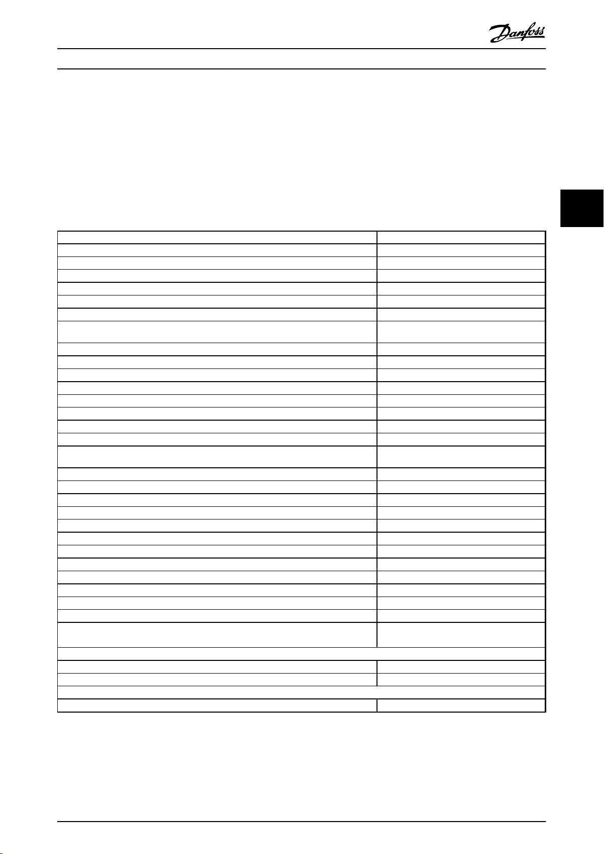
Contents
Contents
VLT® AutomationDrive FC 302 PROFIBUS Converter Operating Instructions
1 Introduction
1.1 About this Manual
1.2 Technical Overview
1.3 Constraints
1.3.1 Software Versions 3
1.3.2 Relations 4
1.3.3 Hardware 4
1.3.4 Performance 5
1.4 Abbreviations
2 Safety
3 How to Install
3.1 Connecting the Bus Line
3.2 How to Install Option in Frequency Converter
3.2.1 Mechanical Installation 8
3.3 EMC Precautions
3
3
3
3
5
6
7
7
7
8
4 How to Configure the System
4.1 Configure the PROFIBUS Network
4.1.1 Setting the PROFIBUS Address using the Hardware Switches 9
4.1.2 Setting the PROFIBUS Address via 9-18 Node Address 9
4.1.3 Commissioning 10
4.2 LED Behaviour
4.3 Initialisation
5 Parameter Mapping Lists
5.1 VLT® 5000 Parameter Group 0
5.2 VLT® 5000 Parameter Group 1
5.3 VLT® 5000 Parameter Group 2
5.4 VLT® 5000 Parameter Group 3
5.5 VLT® 5000 Parameter Group 4
5.6 VLT® 5000 Parameter Group 5
5.7 VLT® 5000 Parameter Group 6
5.8 VLT® 5000 Parameter Group 7
9
9
10
11
12
12
14
18
21
29
34
36
38
5.9 VLT® 5000 Parameter Group 8
5.10 VLT® 5000 Parameter Group 9
6 Troubleshooting
6.1 Step-by-step Troubleshooting
39
40
43
43
MG34N202 - Rev. 2013-10-15 1
Page 4

Contents
VLT® AutomationDrive FC 302 PROFIBUS Converter Operating Instructions
Index
44
2 MG34N202 - Rev. 2013-10-15
Page 5

Introduction
VLT® AutomationDrive FC 302 PROFIBUS Converter Operating Instructions
1 Introduction
1.1 About this Manual
First-time users can find the most essential information for
quick installation and set-up in these chapters:
1.2.1 Technical Overview
1.3 Constraints
3 How to Install
NOTICE
Some parameters in the VLT® 5000 are not supported in
the FC 302 and some FC 302 parameters cannot be
accessed via the PROFIBUS converter option MCA 114.
Refer to 5 Parameter Mapping Lists for more information.
If a write request is attempted to a parameter selection
not supported, the frequency converter discards the
value and issues a positive reply. Only parameters and
functions described in this manual are supported.
1
1
For more detailed information including the full range of
set-up options and diagnosis tools, refer to:
4 How to Configure the System
5 Parameter Mapping Lists
FC 300-related Literature
1.1.1
The following literature is available for the FC 300 series:
VLT® AutomationDrive FC 302 Operating
•
Instructions
VLT® AutomationDrive FC 302 Design Guide
•
VLT® AutomationDrive FC 302 Programming
•
Guide
www.danfoss.com/BusinessAreas/DrivesSolutions/Documentations/VLT+Technical+Documentation.htm
1.2
Technical Overview
The MCA 114 Profibus Converter is an option replacing a
VLT® 5000 with a VLT® AutomationDrive FC 302 in a
PROFIBUS network.
NOTICE
The replacement frequency converter must match the
power size, or be bigger than the replaced VLT® 5000.
Make sure that the brake chopper matches the new
frequency converter.
Make sure that the new frequency converter meets the
local regulations concerning the machinery directive,
prefuses, and other appropriate regulations.
NOTICE
Observe local rules and regulations when replacing
frequency converter in existing installations.
1.3 Constraints
1.3.1 Software Versions
VLT® AutomationDrive FC 302 with firmware
•
version 5.5X or higher.
The MCA 114 Profibus Converter firmware is
•
based on a VLT® 5000 software version 3.9x and
PROFIBUS software version 4.5x.
With this PROFIBUS converter option the FC 302 reacts as
a VLT® 5000 on the PROFIBUS network. Changes to PLC
programming or configuration are normally not necessary.
The FC 302 identifies itself as a VLT® 5000 on the
PROFIBUS network, and a write command to e.g. Ramp Up
Time in VLT® 5000 is automatically linked to the
corresponding ramp up time parameter in VLT® Automa-
tionDrive FC 302.
MG34N202 - Rev. 2013-10-15 3
Page 6
130BT310.11
Introduction
VLT® AutomationDrive FC 302 PROFIBUS Converter Operating Instructions
1
1.3.2 Relations
This manual relates to the following hardware:
VLT® PROFIBUS Converter option, type no.
•
130B1246
MCB 101 General I/O option, type no. 130B1125
•
(uncoated), 130B1212 (coated)
MCB 107 External 24 Volt DC Supply, type no.
•
130B1108 (uncoated), 130B1208 (coated)
PROFIBUS adaptor Sub-D9 connector, type no.
•
130B1112. for enclosure types A1, A2 & A3
PROFIBUS adaptor Sub-D9 connector, type no.
•
176F1742 for enclosure types D & E
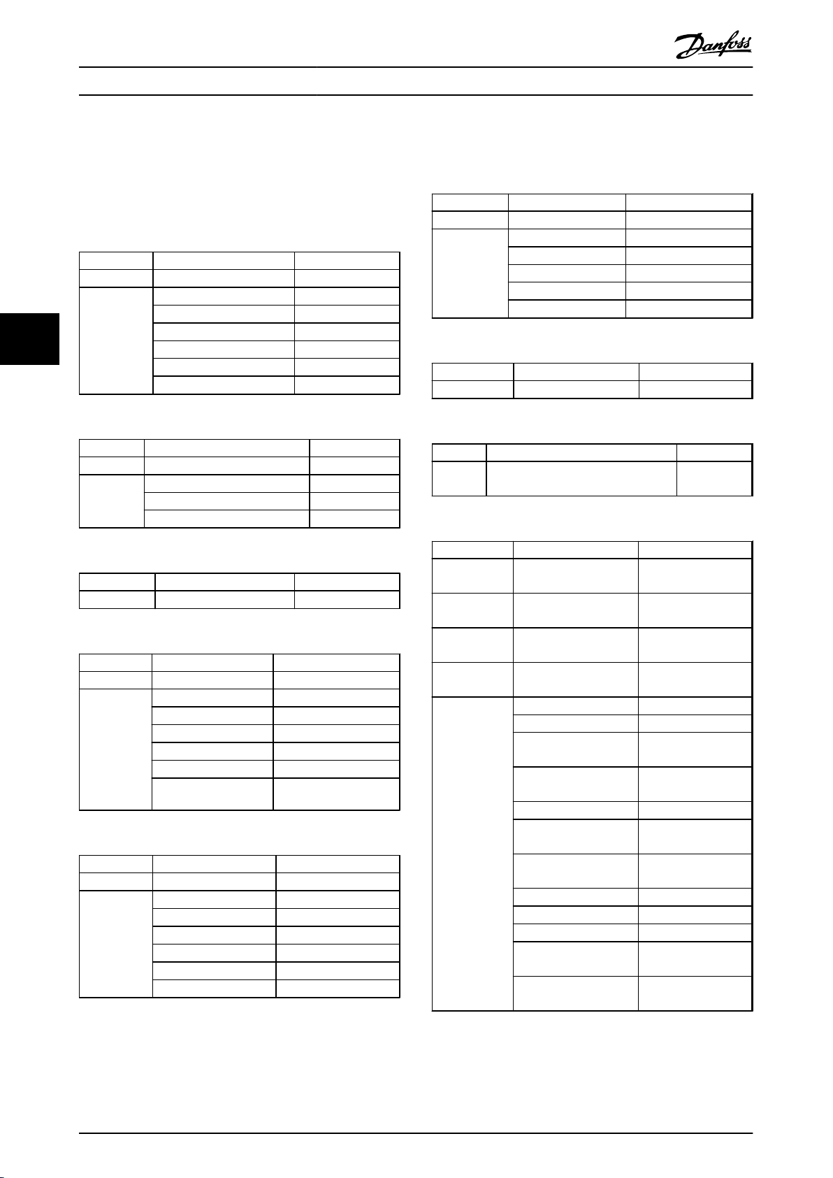
Hardware
1.3.3
The VLT® PROFIBUS Converter MCA 114 supports
•
VLT® AutomationDrive FC 302 only.
There is no support for PROFIBUS FMS networks.
•
The FC 302 has fewer digital I/Os and analog
•
output signals than VLT® 5000. The General I/O
Option MCB 101 must be mounted in FC 302 to
map these signals and utilise all I/Os.
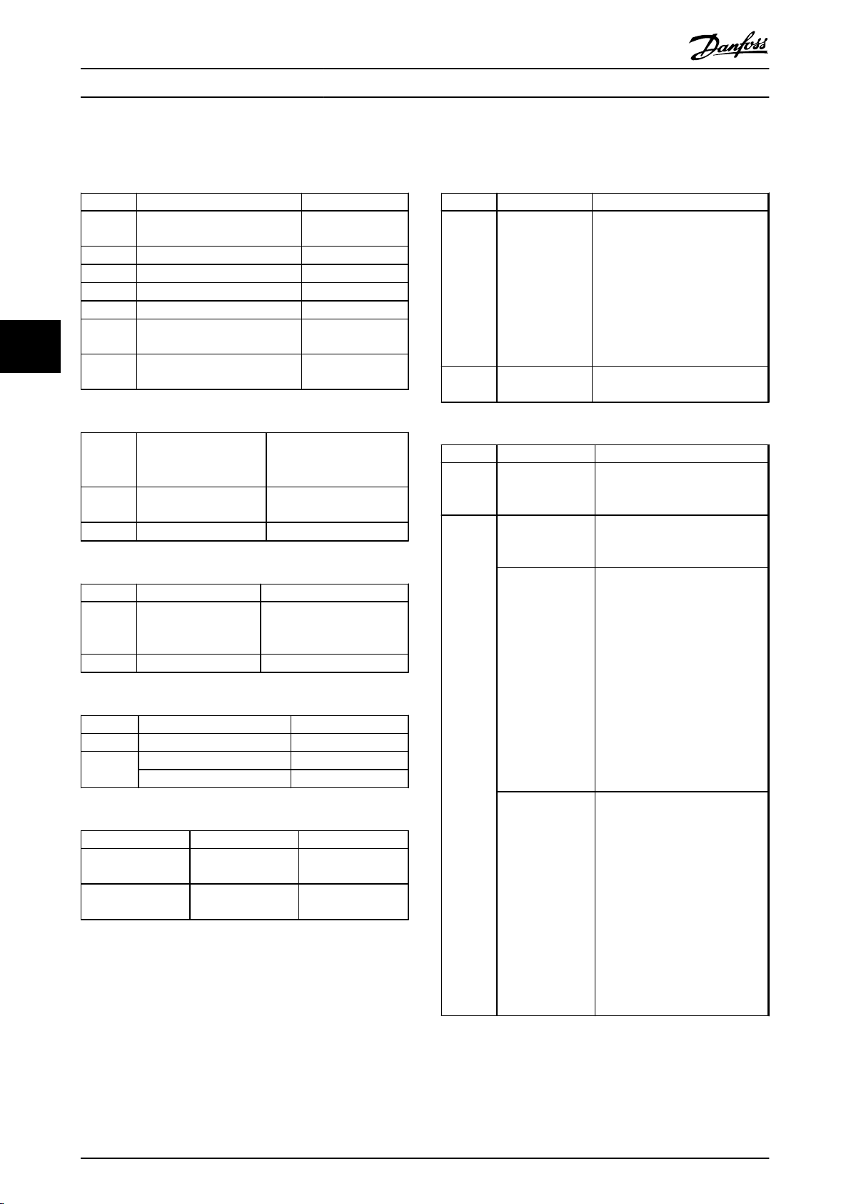
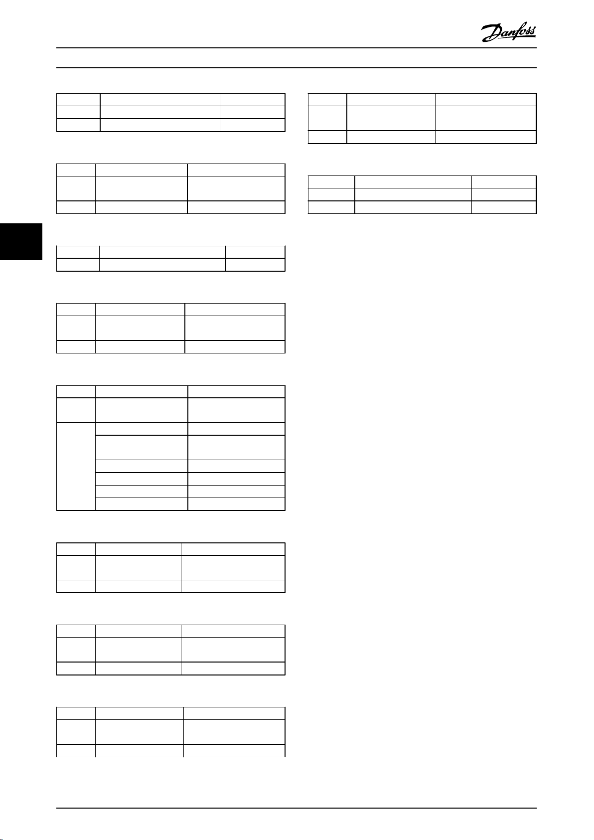
VLT® 5000
FC 302
Terminal Function Terminal Function
01-03 Relay 01-03 Relay
68 RS-485-P 68 RS-485-P
69 RS-485-N 69 RS-485-N
61 GND RS-485 61 GND RS-485
12 24 V out 12 24 V out
13 24 V out 13 24 V out
50 10 V out 50 10 V out
Table 1.1 Terminal Mapping
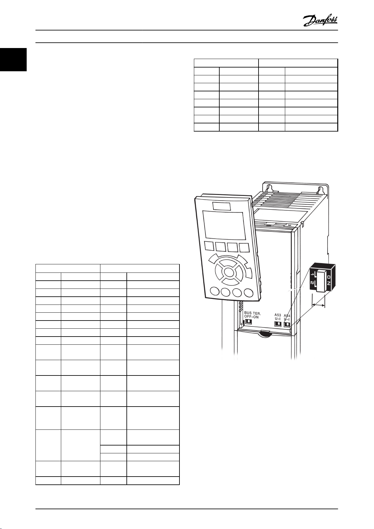
* = General I/O option MCB 101
** = Switch “S201” must be OFF
*** = Switch “S202” must be ON
VLT
®
5000
FC 302
Terminal Function Terminal Function
16 Digital input X30/2* Digital input
17 Digital input X3/3* Digital input
18 Digital input 18 Digital input
19 Digital input 19 Digital input
27 Digital input 27 Digital input
29 Digital input 29 Digital input
32 Digital input 32 Digital input
33 Digital input 33 Digital input
20 GND Digital
input
53 Analog input
voltage
54 Analog input
voltage
60 Analog input
current
55 GND analog/
digital input
voltage
42
39 GND analog/
04-05 Relay 04-06 Relay
Analog/digital
output
digital output
20 GND Digital input
53 Analog input voltage**
X30/11*** Analog input voltage
54 Analog input
55 GND analog/digital
42 Analog output 0/4-20
X30/6* Digital output
X30/7* Pulse output
39 GND analog /digital
current***
input voltage
mA
output
Illustration 1.1 Location of Switches S801, S201, and S202 (Left
to Right)
4 MG34N202 - Rev. 2013-10-15
Page 7
Introduction
VLT® AutomationDrive FC 302 PROFIBUS Converter Operating Instructions
1.3.4 Performance
The dynamic performance on the motor shaft in
•
the closed loop operation compared with VLT
5000 can be different in certain applications. If
necessary, adjust the PID controller manually.
The motor control algorithm of the VLT
•
AutomationDrive FC 302 results in a better motor
performance compared to VLT® 5000.
®
®
NOTICE
Factory values:
After initialisation most parameters are set to match the
factory settings of the VLT® 5000 parameters. For more
information about the initialisation, see the VLT Automa-
tionDrive FC 301/302 Programming Guide.
NOTICE
Linked Set-ups:
To synchronise set-up changes made with running
motor, ensure that FC 302 setups are linked. This is done
in 0-12 This Set-up Linked to.
1
1
1.4 Abbreviations
AOC Application oriented control
CTW Control word
EMC Electromagnetic Compatibility
I/O Input/Output
LED Light Emitting Diode
LSB Least Significant Bit
MAV Main Actual Value (actual output)
MOC Motor oriented control
MSB Most Significant Bit
MRV Main Reference Value (Setpoint)
N/A Not applicable
PCD Peripherals Communication Data (process data)
PCV Parameter Characteristics Value (Parameter
channel)
PLC Programmable Logic Controller
PNU Parameter Number
PPO Parameter Process Data Object
PU Power Unit
REF Reference (= MRV)
STW Status Word
Table 1.2 Abbreviations
MG34N202 - Rev. 2013-10-15 5
Page 8
Safety
2 Safety
VLT® AutomationDrive FC 302 PROFIBUS Converter Operating Instructions
22
WARNING
HIGH VOLTAGE
Frequency converters contain high voltage when
connected to AC mains input power. Failure to perform
installation, start-up, and maintenance by qualified
personnel could result in death or serious injury.
Installation, start-up, and maintenance must be
•
performed by qualified personnel only.
Safety regulations
1. The frequency converter must be disconnected
from mains, if repair work is to be carried out.
Check that the mains supply has been disconnected and that the necessary time has passed
before removing motor and mains plugs, see
Discharge Time Table.
2. The [Off] key does not disconnect the equipment
from mains and is thus not to be used as a safety
switch.
3. Correct protective earthing of the equipment
must be established, the user must be protected
against supply voltage, and the motor must be
protected against overload in accordance with
applicable national and local regulations.
4. The earth leakage currents are higher than 3.5
mA.
5. Protection against motor overload is not included
in the factory setting. If this function is desired,
set 1-90 Motor Thermal Protection [4] ETR trip or
[3] ETR warning.
The function is initialised at 1.16 x rated motor current and
rated motor frequency. For the North American market; the
ETR functions provide class 20 motor overload protection
in accordance with NEC.
6. Do not remove the plugs for the motor and
mains supply while the frequency converter is
connected to mains. Check that the mains supply
has been disconnected and that the necessary
time has passed before removing motor and
mains plugs, see Discharge Time Table.
7. The frequency converter has more voltage inputs
than L1, L2 and L3, when load sharing (linking of
DC intermediate circuit) and external 24 V DC
have been installed. Check that all voltage inputs
have been disconnected and that the necessary
time has passed before commencing repair work,
see Discharge Time Table.
Warning against unintended start
1. The motor can be brought to a stop with digital
commands, bus commands, references or a local
stop, while the frequency converter is connected
to mains. These stop funcyions are not sufficient
to prevent unintended starts.
2. While parameters are being changed, the motor
may start. Consequently, [Off] must always be
activated.
3. A motor that has been stopped may start if faults
occur in the electronics of the frequency
converter, or if a temporary overload or a fault in
the supply mains or the motor connection ceases.
WARNING
Touching the electrical parts may be fatal - even after
the equipment has been disconnected from mains.
Minimum waiting time (minutes)
Voltage [V]
4 15
200-240 0.25-3.7 kW 5.5-37 kW
380-480 0.25-7.5 kW 11-75 kW
525-600 0.75-7.5 kW 11-75 kW
525-690 11-75 kW
High voltage may be present even when the warning LED
indicator lights are off.
Table 2.1 Discharge Time
Also make sure that other voltage inputs have been
disconnected, such as external 24 V DC, load sharing
(linkage of DC intermediate circuit), as well as the motor
connection for kinetic back up.
6 MG34N202 - Rev. 2013-10-15
Page 9
130BT318.11
How to Install
3 How to Install
VLT® AutomationDrive FC 302 PROFIBUS Converter Operating Instructions
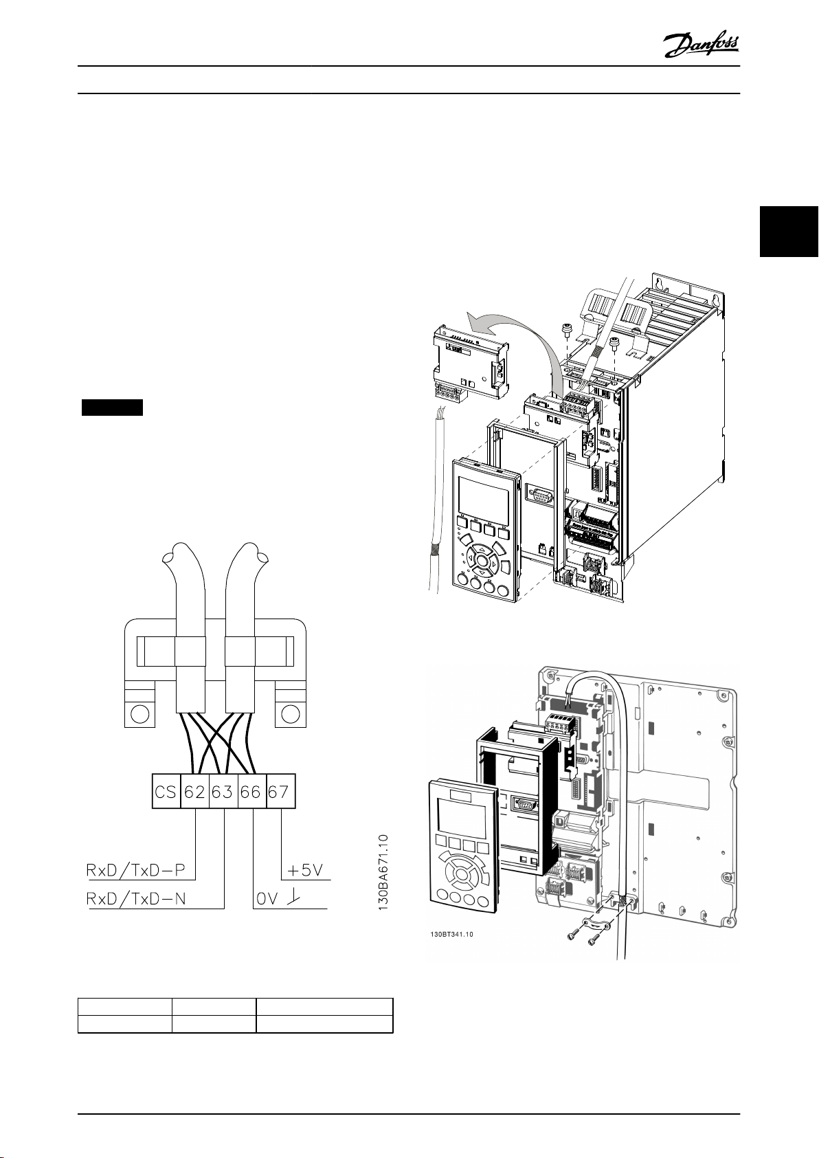
3.1 Connecting the Bus Line
Terminate the bus line at both ends of each segment. A
mismatch of impedance may result in reflections on the
line resulting in corrupt data transmission.
The Profibus Option Card contains a suitable termination.
To activate the termination, turn on Switch 1 on the
Profibus converter option. By default, the switch is turned
off.
NOTICE
Notice that pin numbers are colour
coded on the Profibus connector.
Unlike the VLT
colour-coded to avoid swapping the bus wires.
®
5000, the FC 302 Profibus connectors are
3.2
How to Install Option in Frequency
Converter
Illustration 3.2 Installing Fieldbus Option
3 3
Illustration 3.1 Connecting Bus Wires to VLT PROFIBUS
Converter MCA 114
Profibus B
Profibus A 63 = RxD/TxD Negative, green cable
Table 3.1 Correct Colour-Coding
62 = RxD/TxD Positive, red cable
MG34N202 - Rev. 2013-10-15 7
Illustration 3.3 Cable Holders
1. Remove the LCP from the FC 302.
2. Remove the frame below the local control panel.
Page 10
Fieldbus cable
Min.200mm
90° crossing
130BA080.11
How to Install
VLT® AutomationDrive FC 302 PROFIBUS Converter Operating Instructions
3. Push the option into place. Two positions are
possible, with cable terminal facing either up or
down. The cable up position is often most
suitable when several frequency converters are
installed side by side in a rack, as this position
permits shorter cable lengths.
33
3.2.1 Mechanical Installation
To ease the replacement of VLT 5000 with VLT® AutomationDrive FC 302, there is a number of adapter plates available. The
adapter plates have the same footprints as VLT 5000 and have threaded holes for VLT® AutomationDrive FC 302. The
adapter plate prevents damage that can occur from drilling new threaded holes in the backboard of the enclosure. The
adapter plate also decreases the time required to exchange a broken frequency converter.
The following mechanical adapter plates are available:
Ordering
number
130B0183 Bookstyle, IP20 395 90
130B0184 Bookstyle, IP20 395 130
130B0185 Compact, IP20 395 220
Style Height [mm] Width [mm] Type
4. Push the fieldbus option adaptor frame for the FC
302 into place.
5. Remount the LCP.
6. Attach the cable.
7. Fasten the cable using cable holders.
5001-5003 200-240 V
5001-5005 380-500 V
5004-5006 200-240 V
5006-5011 380-500 V
5001-5003 200-240 V
5001-5005 380-500 V
5004-5006 200-240 V
5006-5011 380-500 V
5001-5011 550-600 V
Table 3.2 Mechanical Installation for VLT® 5000
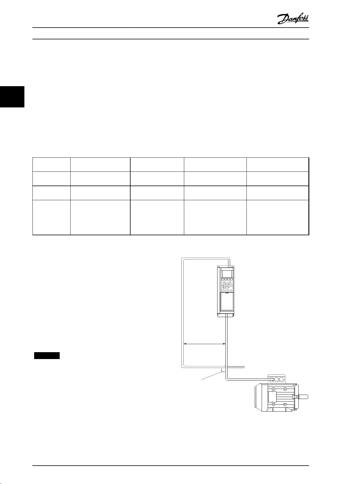
3.3 EMC Precautions
To achieve interference-free operation of the PROFIBUS:
Maintain high distance (min. 200 mm [8"])
•
between the PROFIBUS communication cable and
the motor and brake resistor cables to avoid
coupling of high frequency noise from one cable
to the other.
When crossing is unavoidable, ensure that the
•
PROFIBUS cable crosses motor and brake resistor
cables at an angle of 90 degrees.
NOTICE
Observe relevant national and local regulations, for
example regarding protective earth connection.
Illustration 3.4 Correct EMC Installation
8 MG34N202 - Rev. 2013-10-15
Page 11
MCA 114
Probus
Converter
MS
NS
Option A
130B1246
NS
MS
ON
OFF
S600
ON ON
1
ON
OFF
ON
S300
8 7 6 5 4 3 2
130BA084.11
How to Configure the System
VLT® AutomationDrive FC 302 PROFIBUS Converter Operating Instructions
4 How to Configure the System
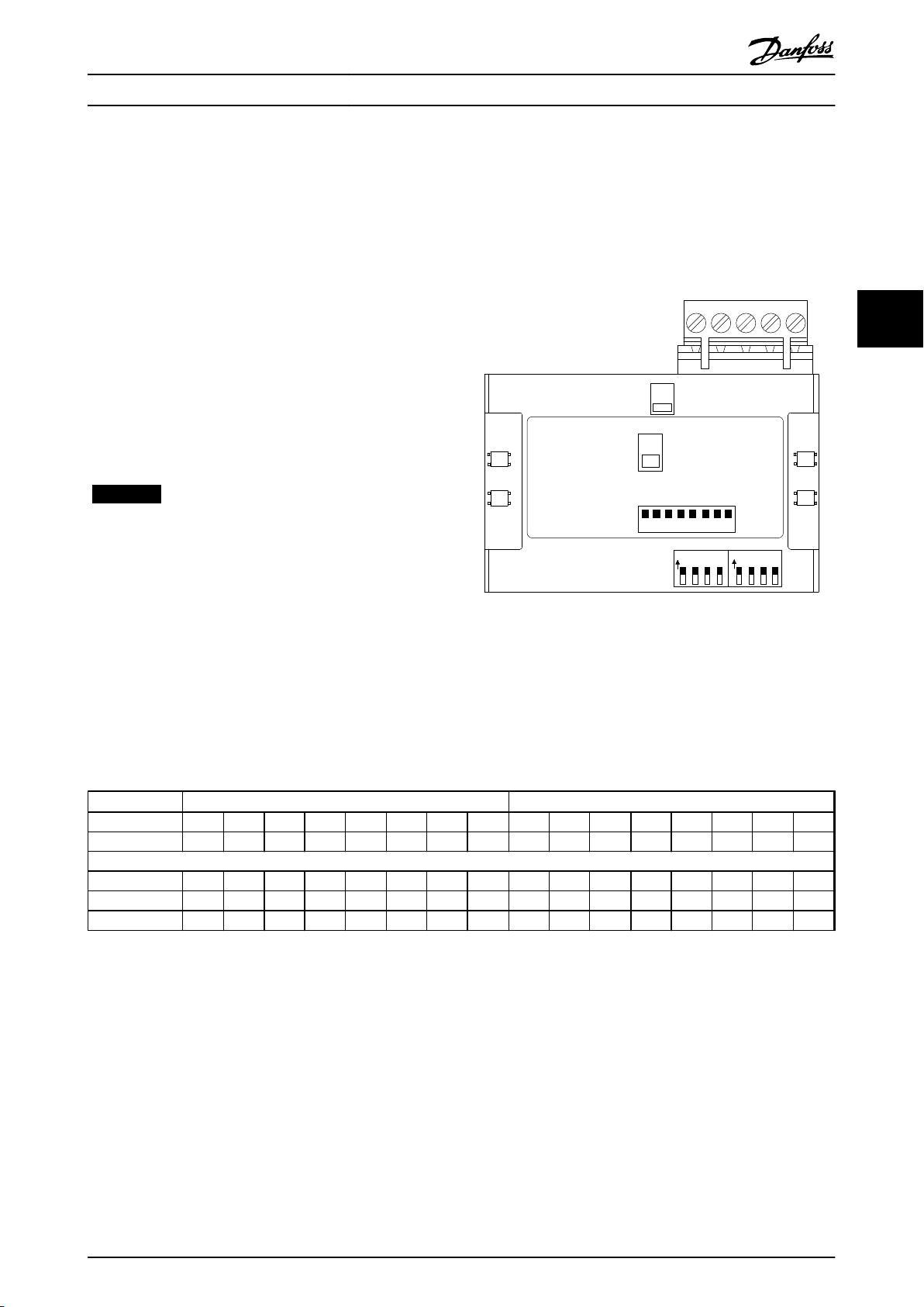
4.1 Configure the PROFIBUS Network
All PROFIBUS stations connected to the same bus network
must have a unique station address.
Before a VLT® 5000 can be replaced with an FC 302 with
MCA 114, only the station address needs to be configured
in the FC 302.
The PROFIBUS address of the FC 302 can be selected via:
Hardware switches
•
9-18 Node Address
•
NOTICE
After installing PROFIBUS Converter MCA 114, check that
8-02 Control Word Source is set to [3] Option A.
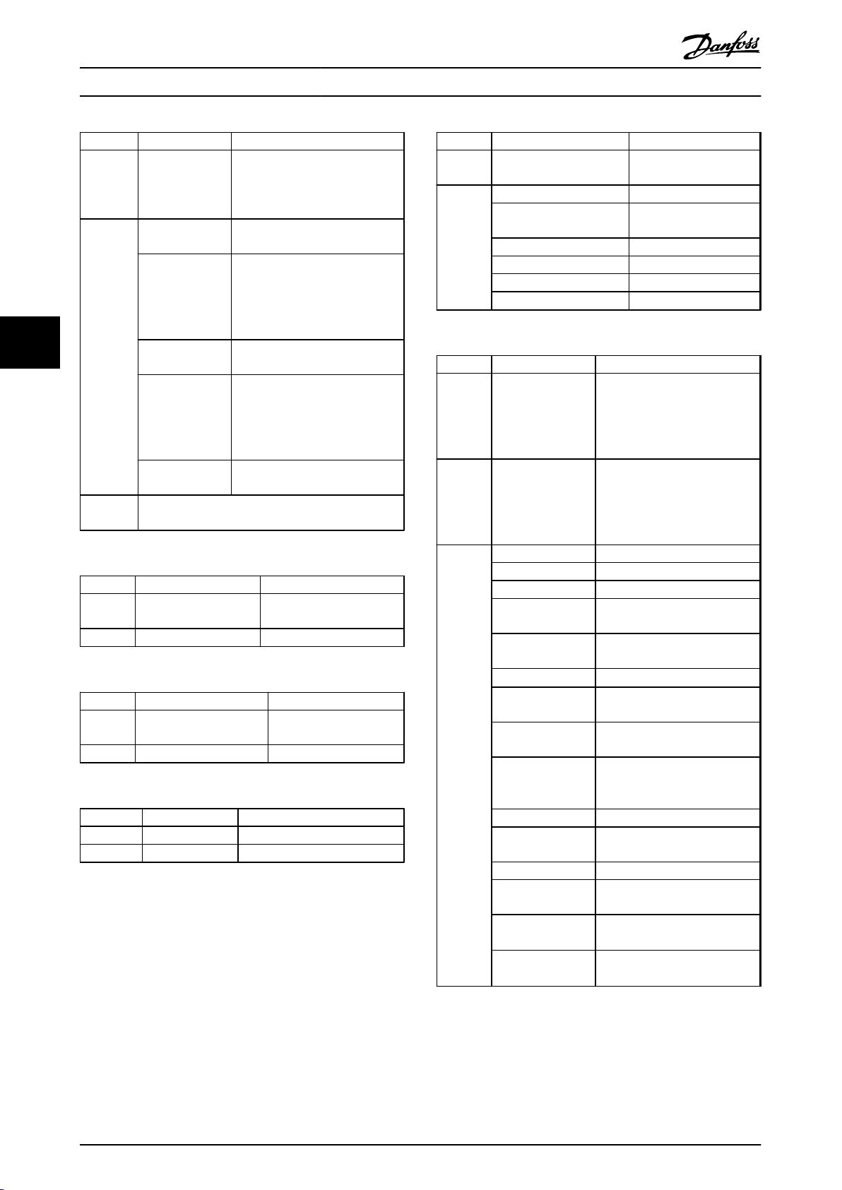
Using the hardware switches, select an address range from
0 to 125 (factory setting 127) according to Illustration 4.1:
ON = 1, OFF = 0
4 4
4.1.1 Setting the PROFIBUS Address using
the Hardware Switches
Illustration 4.1 PROFIBUS Option A
CAUTION
Switch off the power supply before changing the
hardware switches.
CAUTION
The address change comes into effect at the next powerup, and can be read in 9-18 Node Address
Switch 1 2 3 4 5 6 7 8 8 7 6 5 4 3 2 1
Address +1 +2 +4 +8 +16 +32 +64 - - +64 +32 +16 +8 +4 +2 +1
Example:
1 1 0 0 0 0 0 0 - - 0 0 0 0 0 0 1
35 1 1 0 0 0 1 0 - - 0 1 0 0 0 1 1
82 0 1 0 0 1 0 1 - - 1 0 1 0 0 1 0
Table 4.1 Hardware Switches
VLT® 5000
4.1.2 Setting the PROFIBUS Address via
9-18 Node Address
FC 302
Setting the address via 9-18 Node Address or the PROFIBUS
SSA-command is possible, if the hardware switches are set
to 126 or 127 (factory switch setting). The new address
becomes active at the next power-up.
MG34N202 - Rev. 2013-10-15 9
Page 12
How to Configure the System
4.1.3 Commissioning
VLT® AutomationDrive FC 302 PROFIBUS Converter Operating Instructions
After setting the station address from VLT® 5000 to VLT
AutomationDrive FC 302, cycle power on the frequency
®
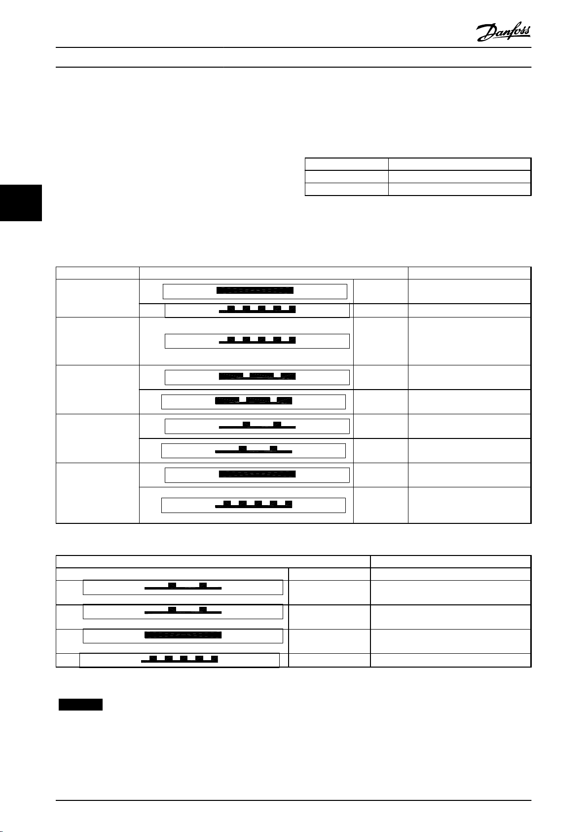
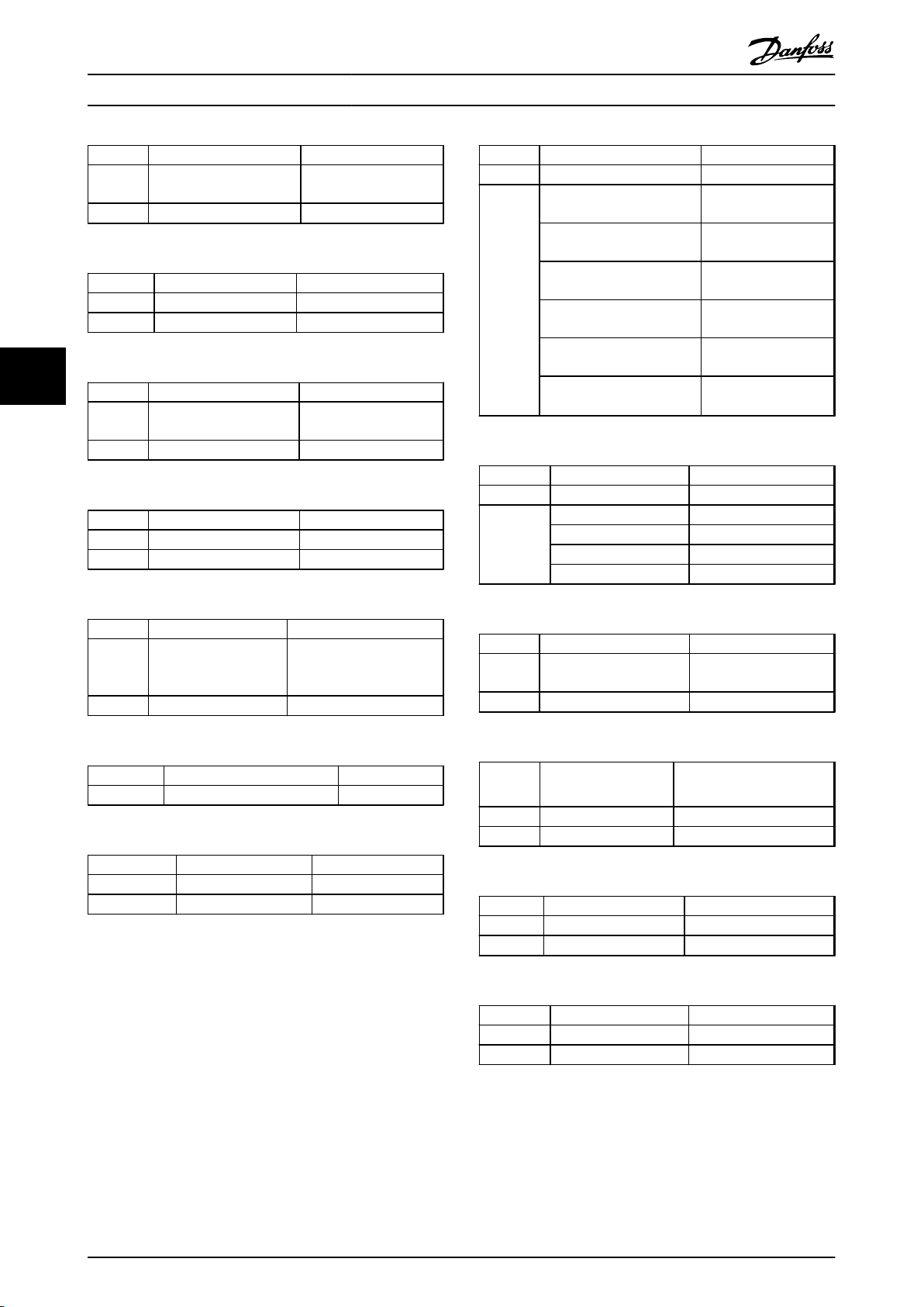
4.2 LED Behaviour
The option has 2 bi-coloured LEDs:
converter to activate the new address. The master/PLC
now recognizes the frequency converter as VLT® 5000. A
solid green NS LED on the MCA 114 option indicates that
communication between the master and the frequency
LED label Description
NS Network Status
MS Modul Status ( DP-V1 communication)
converter is established. If the NS LED flashes, the
44
master/PLC has not recognised the frequency converter.
Table 4.2 Bi Coloured LEDs
For more information, refer to 6.1 Step-by-step Troubleshooting
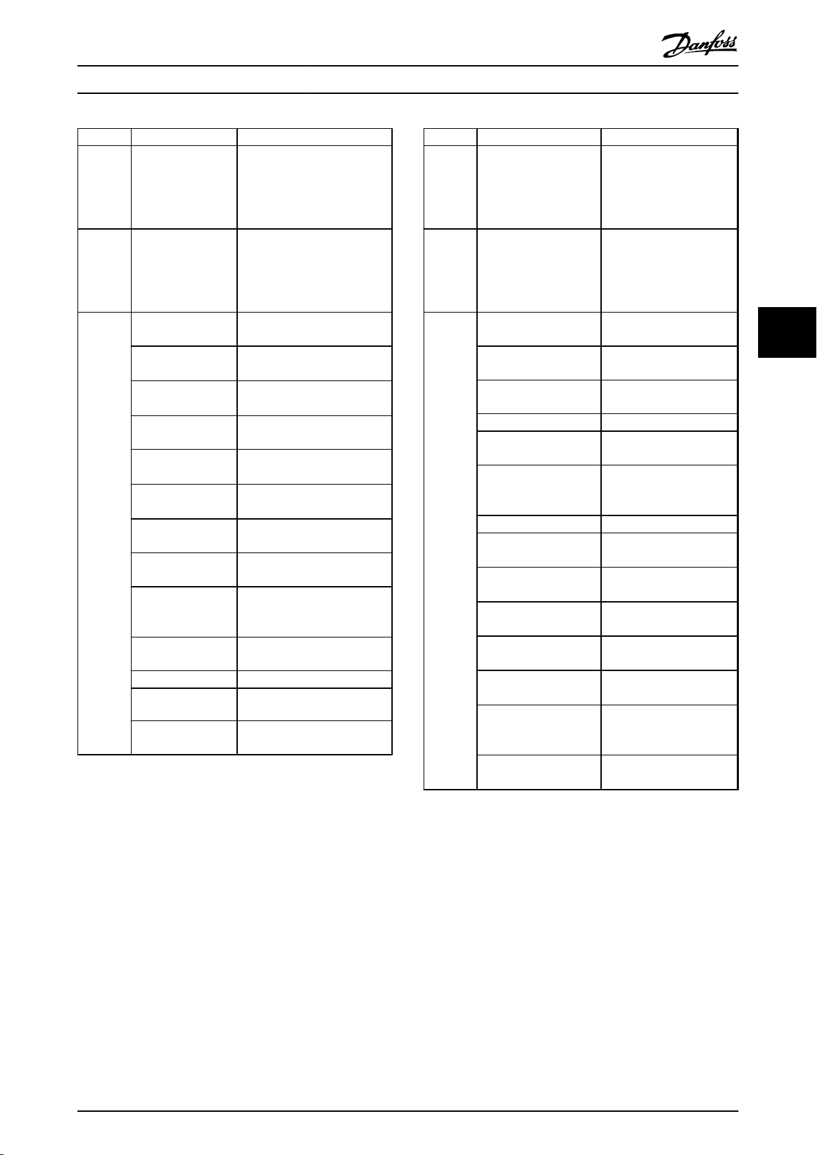
State LED Description
The option is defect. Contact
Danfoss
The option is OK.
Searching for the baud rate.
Check the connection to the
master if the option stays in this
state.
Baud rate found - waiting for
parameters from the master.
Wrong parameters from the
master.
Parameters from master OK –
waiting for configuration data.
Wrong Configuration data from
the master.
Data Exchange between the
master and the FC 300 is active.
Clear State. Warning 34 is active
and a bus reaction in par. 8-04 is
executed.
Power On
Baud rate search
Wait Parameterising
Wait Configuration
Data Exchange
Red:
Green:
Green:
Green:
Red:
Green:
Red:
Green:
Red:
Solid red
Flashing green
Flashing green
Long green
flash
Long red flash
Short green
flash
Short red flash
Solid green
Flashing red
Table 4.3 Net Status
LED Description
No light Off No PROFIBUS DPV1 communication is active.
Green:
Green:
Green:
Red:
Table 4.4 Module Status ( DP-V1 Communication)
Short green flash DP V1 communication from a Master Class 1
(PLC) is active.
Long green flash DP V1 communication from a Master Class 2
(MCT 10, FDT) is active.
Solid green DP V1 communication from a Master Class 1
and 2 is active.
Flashing red Internal error.
NOTICE
The LEDs flash patterns of the MCA114 are not
compatible with the patterns of the VLT®5000 PROFIBUS
LEDs.
10 MG34N202 - Rev. 2013-10-15
Page 13
How to Configure the System
VLT® AutomationDrive FC 302 PROFIBUS Converter Operating Instructions
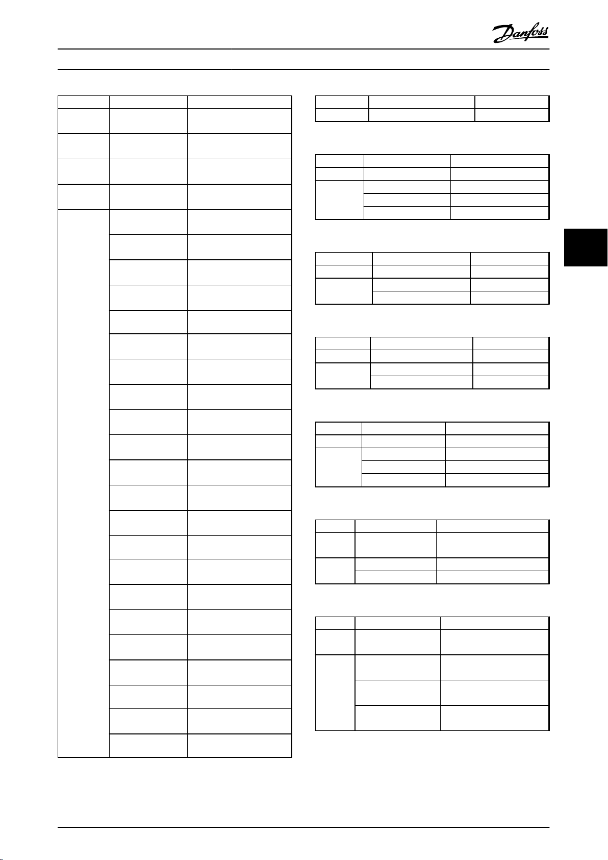
4.3 Initialisation
Factory copy via VLT® 5000 parameter 006 is supported
and initialises the FC 302 and also set it to the VLT® 5000
To achieve the best performance, initialise the frequency
default settings.
converter after the option is mounted. If the frequency
converter is delivered from factory with the option
installed, skip this step. The initialisation is done via
The following parameters are set during the initialisation:
14-22 Operation Mode or a 3 finger reset. The parameters
of the FC 302 are set to factory values, and a number of
FC 302 parameters are set to values that match the VLT
®
5000 initial values.
Parameter Initialisation setting
0-02 Motor Speed Unit [Hz]
1-52 Min Speed Normal Magnetising [Hz] 1.0 Hz
3-16 Reference Resource 2 [0] No function
4-12 Motor Speed Low Limit [Hz] 132.0 Hz
3-00 Reference Range min – max
3-01 Reference/Feedback Unit [1] %
3-11 Jog Speed [Hz] 10.0 Hz
4-30 Motor Feedback Loss Function [0] Disabled
4-56 Warning Feedback Low -4000000
4-57 Warning Feedback High 4000000
6-10 Terminal 53 Low Voltage 0.00 Volt
6-20 Terminal 54 Low Voltage 0.00 Volt
6-22 Terminal 54 Low Current 0.00 Volt
5-51 Term. 29 High Frequency 5000 Hz
5-56 Term. 33 High Frequency 25000 Hz
4-32 Motor Feedback Loss Timeout 1.00 s
4 4
14-21 Automatic Restart Time 5 s
14-03 Overmodulation [0] Off
7-33 Process PID Proportional Gain 0.01
8-54 Reversing Select [0] Digital input
8-90 Bus Jog 1 Speed 300 RPM
8-91 Bus Jog 2 Speed 300 RPM
7-04 Speed PID Differentiation Time OFF
2-10 Brake Function [0] Off
2-17 Over-voltage Control [0] Off
5-40 Function Relay [22] Ready, no thermal Warning
5-41 On Delay, Relay [23] Remote, ready, no TW
7-09 Speed PID Error Correction w/ Ramp 100000 (max)
14-11 Mains Voltage at Mains Fault calculated value: VLT5000 level = FC 302 level
* 1,35 / sqrt(2)
MCB 101 option specific parameters
5-16 Terminal X30/2 Digital Input [1] Reset
5-17 Terminal X30/3 Digital Input [19] Freeze reference
PROFIBUS specific parameters
9-71 Profibus Save Data Values [1] Store all setups
Table 4.5 Parameter Setup at Initialisation
MG34N202 - Rev. 2013-10-15 11
Page 14
Parameter Mapping Lists
5 Parameter Mapping Lists
VLT® AutomationDrive FC 302 PROFIBUS Converter Operating Instructions
5.1
VLT® 5000 Parameter Group 0
Parameter 001 Language select 0-01 Language
Options [0] English [0] English
55
Table 5.1 Conversion of Parameter 001
Parameter 002 Local/remote control Not converted
Options [0] Remote
Table 5.2 Conversion of Parameter 002
Parameter 003 Local reference Not converted
Table 5.3 Conversion of Parameter 003
Parameter 004 Active Set-up 0-10 Active Set-up
Options [0] Factory Setup [0] Factory Setup
Table 5.4 Conversion of Parameter 004
Parameter 005 Setup Copy 0-51 Set-up Copy
Options [0] Factory Set-up [0] Factory Set-up
Table 5.5 Conversion of Parameter 005
VLT 5000 series FC 302 series
[1] Deutsch [1] Deutsch
[2] French [2] French
[3] Dansk [3] Dansk
[4] Spanish [4] Spanish
[5] Italian [5] Italian
VLT 5000 series FC 302 series
[1] Local with External Stop
[2] Local
VLT 5000 series FC 302 series
VLT 5000 series FC 302 series
[1] Setup 1 [1] Setup 1
[2] Setup 2 [2] Setup 2
[3] Setup 3 [3] Setup 3
[4] Setup 4 [4] Setup 4
[5] Multi Setup [9] Multi Setup
VLT 5000 series FC 302 series
[1] Setup 1 [1] Setup 1
[2] Setup 2 [2] Setup 2
[3] Setup 3 [3] Setup 3
[4] Setup 4 [4] Setup 4
[5] Active Setup [9] Active Setup
Parameter 006 Setup Copy 0-51 Set-up Copy
Options [0] No Copy [0] No Copy
Table 5.6 Conversion of Parameter 006
Parameter 007 LCP Copy Not converted
Table 5.7 Conversion of Parameter 007
Parameter 008 Display scaling of motor
Table 5.8 Conversion of Parameter 008
Parameter
number
Parameter
number
Parameter
number
Parameter
number
Options [0] None [0] None
Table 5.9 Conversion of Parameters 009 to 012
VLT 5000 series FC 302 series
[1] [1]
[2] [2]
[3] [3]
[4] [4]
VLT 5000 series FC 302 series
VLT 5000 series FC 302 series
Not converted
frequency
VLT 5000 series FC 302 series
009 Display line 0-23
010 Display line 0-20
011 Display line 0-21
012 Display line 0-22
[1] Reference % [1602] Reference %
[2] Reference [Unit] [1601] Reference
[Unit]
[3] Feedback [Unit] [1652] Feedback
[Unit]
[4] Frequency [Hz] [1613] Frequency [Hz]
[5] Frequency x scale [1609] Custom
readout
[6] Motor current [A] [1614] Motor current
[A]
[7] Torque [%] [1622] Torque [%]
[8] Power [kW] [1610] Power [kW]
[9] Power [HP] [1611] Power [HP]
[10] Output energy
[kWh]
[11] Motor voltage [V] [1612] Motor voltage
[1502] kWh counter
[kWh]
[V]
12 MG34N202 - Rev. 2013-10-15
Page 15
Parameter Mapping Lists
VLT® AutomationDrive FC 302 PROFIBUS Converter Operating Instructions
Parameter
number
Parameter
number
Parameter
number
Parameter
number
Options [12] DC link voltage
VLT 5000 series FC 302 series
009 0-09 Performance Monitor
010 0-10 Active Set-up
011 0-11 Edit Set-up
012 0-12 This Set-up Linked to
[V]
[13] Thermal load,
motor [%]
[14] Thermal load,
VLT® [%]
[15] Running hours
[hours]
[16] Digital input [1660] Digital input
[17] Analogue input
53 [V]
[18] Analogue input
54 [V]
[19] Analogue input
60 [mA]
[20] Pulse reference
[Hz]
[21] Ext. reference
[%]
[22] Status word
[hex]
[23] Brake effect/2
min [kW]
[24] Brake effect/sec
[kW]
[25] Heat sink temp. [1634] Heat sink temp.
[26] Alarm word
[hex]
[27] Control word
[hex]
[28] Warning word 1
[hex]
[29] Warning word 2
[hex]
[30] Com. Option
warning [hex]
[31] RPM [min] [1617] Speed RPM [min]
[32] RPM x scaling
[min]
[33] LCP display text Not possible
[1630] DC link voltage [V]
[1618] Thermal load, motor
[%]
[1635] Inverter thermal [%]
[1501] Running hours
[hours]
[1662] Analogue input 53
[V]
[1664] Analogue input 54
[V]
[1662] Analogue input 53
[mA]
[1651] Pulse reference [Hz]
[1650] Ext. reference [%]
[1603] Status word [hex]
[1633] Brake effect/2 min
[kW]
[1632] Brake effect/sec [kW]
[1600] Control word [hex]
[953] Com. Option warning
[hex]
[1609] Custom readout
Parameter 013 Local Ctrl./config Not converted
Table 5.11 Conversion of Parameter 013
Parameter 014 Local Stop key 0-41 [Off] Key on LCP
Options [0] Disable [0] Disable
Table 5.12 Conversion of Parameter 014
Parameter 015 Local Jogging Not converted
Options [0] Disable
Table 5.13 Conversion of Parameter 015
Parameter 016 Local Reversing Not converted
Options [0] Disable
Table 5.14 Conversion of Parameter 016
Parameter 017 Local Stop key 0-43 [Reset] Key on LCP
Options [0] Disable [0] Disable
Table 5.15 Conversion of Parameter 017
Parameter 018 Lock for data
Options [0] Not locked [0] Full access
Table 5.16 Conversion of Parameter 018
Parameter 019 Power-Up Mode 0-04 Operating State at
Options [0] Auto Restart, use
Table 5.17 Conversion of Parameter 019
VLT 5000 series FC 302 series
VLT 5000 series FC 302 series
[1] Enable [1] Enable
[2] Password
VLT 5000 series FC 302 series
[1] Enable
VLT 5000 series FC 302 series
[1] Enable
VLT 5000 series FC 302 series
[1] Enable [1] Enable
[2] Password
VLT 5000 series FC 302 series
0-61 Access to Main Menu
change
[1] Lock [1] LCP: Read only
VLT 5000 series FC 302 series
saved ref.
[1] Forced stop, use
saved ref.
[2] Forced stop, set ref
= 0.
w/o Password
Power-up (Hand)
[0] Resume
[1] Forced stop, use saved
ref.
[2] Forced stop, set ref = 0
5 5
Table 5.10 Conversion of Parameters 009 to 012
MG34N202 - Rev. 2013-10-15 13
Page 16

Parameter Mapping Lists
VLT® AutomationDrive FC 302 PROFIBUS Converter Operating Instructions
Parameter 027 Warning readout line Not converted
Options [0] Warning in line 1/2
Table 5.18 Conversion of Parameter 027
55
VLT 5000 series FC 302 series
[1] Warning in line 3/4
5.2
VLT® 5000 Parameter Group 1
Parameter 100 Configuration 0-02
Options [0] Speed control,
Table 5.19 Conversion of Parameter 100
Parameter 101 Torque charac-
Options [1] High constant
VLT 5000 series FC 302 series
1-01 Motor Control Principle
Par. 1-00 = [0] Speed open loop
open loop
[1] Speed control,
closed loop
[3] Process
control, closed
loop
[4] Torque control,
open loop
[5] Torque control,
speed feedback
VLT 5000 series FC 302 series
teristic
torque
[2] High variable
torque low
[3] High variable
torque medium
[4] High variable
torque high
[5] High special
motor characteristic
[6] High variable
torque with low
starting torque
Par. 1-01 = [1] VVC
Par. 0-02 = [0] RPM
Par. 1-00 = [1] Speed closed loop
Par. 1-00 = [3] Process
Par. 1-01 = [1] VVC
Par. 1-00 = [4] Torque open loop
Par.1-01 = [1] VVC
Par. 1-00 = [2] Torque close loop
Par. 1-01 = [3] Flux with motor fb
Par. 5-71 = [1] Counter clockwise
1-03 Torque Characteristics
1-04 Overload Mode
14-40 VT Level
Par. 1-03 = [0] Constant torque
Par. 1-04 Over load = [0] High
Par. 1-03 = [1] Variable torque
Par. 14-40 VT level = 45%
Par. 1-04 Over load = [0] High
Par. 1-03 = [1] Variable torque
Par. 14-40 VT level = 66%
Par. 1-04 Over load = [0] High
Par. 1-03 = [1] Variable torque
Par. 14-40 VT level = 85%
Par. 1-04 Over load = [0] High
Par. 1-01 = [0] U/f
Par. 1-04 Over load = [0] High
Par. 1-03 = [1] Variable torque
Par. 14-40 VT level = 45%
Par. 1-04 Over load = [0] High
plus
plus
plus
Table 5.20 Conversion of Parameter 101
14 MG34N202 - Rev. 2013-10-15
Page 17

Parameter Mapping Lists
VLT® AutomationDrive FC 302 PROFIBUS Converter Operating Instructions
Parameter 101 Torque charac-
Options [7] High variable
VLT 5000 series FC 302 series
teristic
torque with
medium starting
torque
[8] High variable
torque with high
starting torque
[11] Normal
constant torque
[12] Normal
variable torque low
[13] Normal
variable torque
medium
[14] Normal
variable torque
high
[15] Normal special
motor characteristic
[16] Normal
variable torque
with low constant
starting torque
[17] Normal
variable torque
with medium
constant starting
torque
[18] Normal
variable torque
with high constant
starting torque
1-03 Torque Characteristics
1-04 Overload Mode
14-40 VT Level
Par. 1-03 = [1] Variable torque
Par. 14-40 VT level = 66%
Par. 1-04 Over load = [0] High
Par. 1-03 = [1] Variable torque
Par. 14-40 VT level = 85%
Par. 1-04 Over load = [0] High
Par. 1-03 = [0] Constant torque
Par. 1-04 Over load = [1] Normal
Par. 1-03 = [1] Variable torque
Par. 14-40 VT level = 45%
Par. 1-04 Over load = [1] Normal
Par. 1-03 = [1] Variable torque
Par. 14-40 VT level = 66%
Par. 1-04 Over load = [1] Normal
Par. 1-03 = [1] Variable torque
Par. 14-40 VT level = 85%
Par. 1-04 Over load = [1] Normal
Par. 1-01 = [0] U/f
Par. 1-04 Over load = [1] Normal
Par. 1-03 = [1] Variable torque
Par. 14-40 VT level = 45%
Par. 1-04 Over load = [1] Normal
Par. 1-03 = [1] Variable torque
Par. 14-40 VT level = 66%
Par. 1-04 Over load = [1] Normal
Par. 1-03 = [1] Variable torque
Par. 14-40 VT level = 85%
Par. 1-04 Over load = [1] Normal
Parameter 105 Motor Current 1-24 Motor Current
Range Power Unit dependable Power Unit dependable
Table 5.25 Conversion of Parameter 105
Parameter 106 Rated motor speed 1-25 Motor Nominal Speed
Range 100 – 60000 10 – 60000
Table 5.26 Conversion of Parameter 106
Parameter 107 Automatic motor
Options [0] Adaptation off [0] Off
Table 5.27 Conversion of Parameter 107
Parameter 108 Stator resistor 1-30 Stator Resistance (Rs)
Range Power Unit dependable 0.0140 – 140.0000
Table 5.28 Conversion of Parameter 108
Parameter 109 Stator reactance 1-35 Main Reactance (Xh)
Range Power Unit dependable 1.0000 – 10000.0000
Table 5.29 Conversion of Parameter 109
Parameter 110 Motor magnetizing at
Range 0 – 300% 0 – 300%
VLT 5000 series FC 302 series
VLT 5000 series FC 302 series
VLT 5000 series FC 302 series
1-29 Automatic Motor
adaptation
[1] Adaptation on, Rs
and Xs
[2] Adaptation on, RS [2] Enable reduce AMA
VLT 5000 series FC 302 series
VLT 5000 series FC 302 series
VLT 5000 series FC 302 series
0 RPM
Adaptation (AMA)
[1] Enable complete AMA
1-50 Motor Magnetisation at Zero Speed
5 5
Table 5.21 Conversion of Parameter 101
Parameter 102 Motor Power 1-20 Motor Power [kW]
Range 0.18 – 600 kW 0.09 – 3000 kW
Table 5.22 Conversion of Parameter 102
Parameter 103 Motor Voltage 1-22 Motor Voltage
Range 200 – 600 Volt 50 – 1000 V
Table 5.23 Conversion of Parameter 103
Parameter 104 Motor frequency 1-23 Motor Frequency
Range 20 -1000 Hz 20 -1000 Hz
Table 5.24 Conversion of Parameter 104
VLT 5000 series FC 302 series
VLT 5000 series FC 302 series
VLT 5000 series FC 302 series
MG34N202 - Rev. 2013-10-15 15
Table 5.30 Conversion of Parameter 110
Parameter 111 Min. frequency
Range 0.1 – 10.0 Hz 0.3 – 10.0 Hz
Table 5.31 Conversion of Parameter 111
Parameter 113 Load compensation at
Range 0 – 300% 0 – 300%
Table 5.32 Conversion of Parameter 113
VLT 5000 series FC 302 series
low speed
VLT 5000 series FC 302 series
1-52 Min Speed
normal magnetizing
Normal Magnetising
[Hz]
1-60 Low Speed Load
Compensation
Page 18
Parameter Mapping Lists
VLT® AutomationDrive FC 302 PROFIBUS Converter Operating Instructions
Parameter 114 Load compensation at
Range 0 – 300% 0 – 300%
Table 5.33 Conversion of Parameter 114
Parameter 115 Slip Compensation 1-62 Slip Compensation
Range -500 - 500% -500 - 500%
Table 5.34 Conversion of Parameter 115
55
Parameter 116 Slip Compensation
Range 0.05 – 1.00 s 0.05 – 5.00 s
Table 5.35 Conversion of Parameter 116
Parameter 117 Resonance dampening 1-64 Resonance Damping
Range 0 - 500% 0 - 500%
Table 5.36 Conversion of Parameter 117
Parameter 118 Resonance
Range 5 – 50 ms 5 – 50 ms
VLT 5000 series FC 302 series
1-61 High Speed Load
high speed
VLT 5000 series FC 302 series
VLT 5000 series FC 302 series
Time constant
VLT 5000 series FC 302 series
VLT 5000 series FC 302 series
dampening time
constant
Compensation
1-63 Slip Compensation
Time Constant
1-65 Resonance Damping
Time Constant
Parameter 121 Start function 1-72 Start Function
Options [0] DC hold in start delay
Table 5.40 Conversion of Parameter 121
Parameter 122 Function at stop 1-80 Function at Stop
Options [0] Coasting [0] Coast
Table 5.41 Conversion of Parameter 122
Parameter 123 Min frequency for
Range 0.0 – 10.0 Hz 0.0 – 20.0 Hz
VLT 5000 series FC 302 series
[0] DC hold/delay time
time
[1] DC brake in start delay
time
[2] Coasting in start delay
time
[3] Start frequency/voltage
clockwise
[4] Start frequency/voltage
in reference direction
plus
[5] VVC
VLT 5000 series FC 302 series
function at stop
clockwise [5] VVC
VLT 5000 series FC 302 series
[1] DC hold [1] DC hold
[2] Motor check [2] Motor check
[3] Pre-magnetizing [3] Pre-magnetizing
[1] DC Brake/delay
time
[2] Coast/delay time
[3] Start speed cw
[4] Horizontal
operation
plus
/Flux
clockwise
1-82 Min Speed for
Function at Stop [Hz]
Table 5.37 Conversion of Parameter 118
Parameter 119 High starting torque Not converted
Table 5.38 Conversion of Parameters 119
Parameter 120 Start delay
Option 0.0 – 10.0 s 0.0 – 10.0 s
Table 5.39 Conversion of Parameter 120
VLT 5000 series FC 302 series
VLT 5000 series FC 302 series
1-71 Start Delay
Table 5.42 Conversion of Parameter 123
Parameter 124 DC holding current 2-00 DC Hold Current
Range 0 - 100% 0 - 160% (motor depending)
Table 5.43 Conversion of Parameter 124
Parameter 125 DC braking current 2-01 DC Brake Current
Range 0 - 100% 0 – 160% P.U depending
Table 5.44 Conversion of Parameter 125
Parameter 126 DC braking time 2-02 DC Braking Time
Range 0.0 – 60.0 s 0.0 – 60.0 s
Table 5.45 Conversion of Parameter 126
VLT 5000 series FC 302 series
VLT 5000 series FC 302 series
VLT 5000 series FC 302 series
16 MG34N202 - Rev. 2013-10-15
Page 19

Parameter Mapping Lists
VLT® AutomationDrive FC 302 PROFIBUS Converter Operating Instructions
Parameter 127 DC brake cut-in
Range 0.0 (Off) – f
Table 5.46 Conversion of Parameter 127
Parameter 128 Motor thermal
Options [0] No protection [0] No protection
[1] Thermistor warning [1] Thermistor warning
[2] Thermistor trip [2] Thermistor trip
[3] ETR warning 1 [3] ETR warning 1
[4] ETR trip 1 [4] ETR trip 1
[5] ETR warning 2 [5] ETR warning 2
[6] ETR trip 2 [6] ETR trip 2
[7] ETR warning 3 [7] ETR warning 3
[8] ETR trip 3 [8] ETR trip 3
[9] ETR warning 4 [9] ETR warning 4
[10] ETR trip 4 [10] ETR trip 4
Table 5.47 Conversion of Parameter 128
VLT 5000 series FC 302 series
2-04 DC Brake Cut In
frequency
(par. 202) 0.0 (Off) – f
max
VLT 5000 series FC 302 series
protection
Speed [Hz]
1-90 Motor Thermal
Protection
max
(par. 414)
5 5
Parameter 129 External motor fan 1-91 Motor External Fan
Options [0] No [0] No
[1] Yes [1] Yes
Table 5.48 Conversion of Parameter 129
Parameter 130 Start frequency 1-75 Start Speed [Hz]
Range 0.0 – 10.0 Hz 0.0 – 500 Hz P.U depending
Table 5.49 Conversion of Parameter 130
Parameter 131 Initial voltage Not converted
Table 5.50 Conversion of Parameter 131
Parameter 145 Minimum DC brake time Not converted
Table 5.51 Conversion of Parameter 132
VLT 5000 series FC 302 series
VLT 5000 series FC 302 series
VLT 5000 series FC 302 series
VLT 5000 series FC 302 series
MG34N202 - Rev. 2013-10-15 17
Page 20
Parameter Mapping Lists
5.3
VLT® 5000 Parameter Group 2
VLT® AutomationDrive FC 302 PROFIBUS Converter Operating Instructions
Parameter 200 Output Frequency Range/
Options [0] Only clockwise, 0 – 132 Hz [0] Clockwise
[1] Both directions, 0 – 132 Hz [2] Both directions
[2] Only clockwise, 0 – 1000 Hz [0] Clockwise
[3] Both directions, 0 – 1000 Hz [2] Both directions
[4] Only counter clockwise, 0 –
55
[5] Only counter clockwise, 0 –
Table 5.52 Conversion of Parameter 200
Parameter 201 Output frequency
Range 0.0 – par. 202 F
Table 5.53 Conversion of Parameter 201
Parameter 202 Output frequency
Range 0.0 – 132/1000 Hz 0 – 1000 Hz
Table 5.54 Conversion of Parameter 202
Parameter 203 Reference/feedback area 3-00 Reference Range
Options [0] Min – Max [0] Min – Max
Table 5.55 Conversion of Parameter 203
Parameter 204 Minimum
Range -100,000.000 – par.
Table 5.56 Conversion of Parameter 204
VLT 5000 series FC 302 series
4-10 Motor Speed
Direction
132 Hz
1000 Hz
VLT 5000 series FC 302 series
low limit
max
VLT 5000 series FC 302 series
high limit
VLT 5000 series FC 302 series
[1] - Max - +Max [1] - Max - +Max
VLT 5000 series FC 302 series
reference
205 Ref
max
Direction
[1] Counter
clockwise
[1] Counter
clockwise
4-12 Motor Speed Low
Limit [Hz]
0 – par. 414 F
4-14 Motor Speed High
Limit [Hz]
4-19 Max Output Frequency
3-02 Minimum
Reference
-100,000.000 – par.
3-03 Ref
max
max
[Hz]
Parameter 205 Maximum
Range Par. 204 Ref
Table 5.57 Conversion of Parameter 205
Parameter 206 Ramp Type 3-40 Ramp 1 Type
Options [0] Linear Par. 3-40 = [0] Linear
VLT 5000 series FC 302 series
3-03 Maximum Reference
reference
100,000.000
VLT 5000 series FC 302 series
[1] Sine shape (S1) Par. 3-40 = [2] S-ramp Const Time
[2] Sin2 Shape
(S2)
6-15 Terminal 53 High Ref./Feedb.
Value
6-25 Terminal 54 High Ref./Feedb.
Value
5-53 Term. 29 High Ref./Feedb.
Value
5-58 Term. 33 High Ref./Feedb.
Value
–
Par. 3-02 Ref
min
3-50 Ramp 2 Type
3-82 Quick Stop Ramp Type
Par. 3-50 = [0] Linear
Par. 3-82 = [0] Linear
Par. 3-45 = 1%
Par. 3-46 = 25%
Par. 3-47 = 1%
Par. 3-48 = 25%
Par. 3-50 = [2] S-ramp Const Time
Par. 3-55 = 1%
Par. 3-56 = 25%
Par. 3-57 = 1%
Par. 3-58 = 25%
Par. 3-82 = [2] S-ramp Const Time
Par. 3-83 = 1%
Par. 3-84 = 25%
Par. 3-40 = [2] S-ramp Const Time
Par. 3-45 = 25%
Par. 3-46 = 25%
Par. 3-47 = 25%
Par. 3-48 = 25%
Par. 3-50 = [2] S-ramp Const Time
Par. 3-55 = 25%
Par. 3-56 = 25%
Par. 3-57 = 25%
Par. 3-58 = 25%
Par. 3-82 = [2] S-ramp Const Time
Par. 3-83 = 25%
Par. 3-84 = 25%
– 100,000.000
min
Table 5.58 Conversion of Parameter 206
18 MG34N202 - Rev. 2013-10-15
Page 21

Parameter Mapping Lists
VLT® AutomationDrive FC 302 PROFIBUS Converter Operating Instructions
Parameter 206
Options [0]
Table 5.59 Conversion of Parameter 206
Parameter 207 Ramp up Time 1 3-41 Ramp 1 Ramp Up Time
Range 0.05 – 3600.00 s 0.01 – 3600.00 s
Table 5.60 Conversion of Parameter 207
Parameter 208 Ramp down Time 1 3-42 Ramp 1 Ramp Down
Range 0.05 – 3600.00 s 0.01 – 3600.00 s
Table 5.61 Conversion of Parameter 208
Parameter 209 Ramp up Time 2 3-51 Ramp 2 Ramp Up Time
Range 0.05 – 3600.00 s 0.01 – 3600.00 s
Table 5.62 Conversion of Parameter 209
Parameter 210 Ramp down Time 2 3-52 Ramp 2 Ramp Down
Range 0.05 – 3600.00 s 0.01 – 3600.00 s
VLT
5000
series
Ramp
Type
Linear
[3] Sin3
Shape
(S3)
[4] Sin2
filter
VLT 5000 series FC 302 series
VLT 5000 series FC 302 series
VLT 5000 series FC 302 series
VLT 5000 series FC 302 series
FC 302 series
3-40 Ramp 1 Type3-50 Ramp 2
Type3-82 Quick Stop Ramp Type
[0] Linear. Write to p.340, 350 and 382
Par. 3-40 = [2] S-ramp Const Time
Par. 3-45 = 50%
Par. 3-46 = 50%
Par. 3-47 = 50%
Par. 3-48 = 50%
Par. 3-50 = [2] S-ramp Const Time
Par. 3-55 = 50%
Par. 3-56 = 50%
Par. 3-57 = 50%
Par. 3-58 = 50%
Par. 3-82 = [2] S-ramp Const Time
Par. 3-83 = 50%
Par. 3-84 = 50%
Par. 3-40 = [2] S-ramp Const Time
Par. 3-45 = 25%
Par. 3-46 = 25%
Par. 3-47 = 25%
Par. 3-48 = 25%
Par. 3-50 = [2] S-ramp Const Time
Par. 3-55 = 25%
Par. 3-56 = 25%
Par. 3-57 = 25%
Par. 3-48 = 25%
Par. 3-82 = [2] S-ramp Const Time
Par. 3-83 = 25%
Par. 3-84 = 25%
Time
Time
Parameter 211 Jog ramp time 3-80 Jog Ramp Time
Range 0.05 – 3600.00 s 0.01 – 3600.00 s
Table 5.64 Conversion of Parameter 211
Parameter 212 Quick stop ramp
Range 0.05 – 3600.00 s 0.01 – 3600.00 s
Table 5.65 Conversion of Parameter 212
Parameter 213 Jog Frequency 3-11 Jog Speed [Hz]
Range 0.0 – par. 202 0.0 – par. 4-14
Table 5.66 Conversion of Parameter 213
Parameter 214 Reference function 3-04 Reference Function
Options [0] Sum [0] Sum
Table 5.67 Conversion of Parameter 214
*= Relative reference is added to the MRV from PROFIBUS.
Parameter 215 Preset Reference 1 3-10 Preset Reference
Range -100.00 – 100.00% -100.00 – 100.00%
Table 5.68 Conversion of Parameter 215
Parameter 216 Preset Reference 2 3-10 Preset Reference
Range -100.00 – 100.00% -100.00 – 100.00%
Table 5.69 Conversion of Parameter 216
Parameter 217 Preset Reference 3 3-10 Preset Reference
Range -100.00 – 100.00% -100.00 – 100.00%
Table 5.70 Conversion of Parameter 217
Parameter 218 Preset Reference 4 3-10 Preset Reference
Range -100,00 - 100,00% -100,00 - 100,00%
Table 5.71 Conversion of Parameter 218
Parameter 219 Catch up/slow
Range 0.00 – 100% 0.00 – 100%
Table 5.72 Conversion of Parameter 219
VLT 5000 series FC 302 series
VLT 5000 series FC 302 series
3-81 Quick Stop Ramp
time
VLT 5000 series FC 302 series
VLT 5000 series FC 302 series
[1] Relative See comment below*
[2] External/Preset [2] External/Preset
VLT 5000 series FC 302 series
VLT 5000 series FC 302 series
VLT 5000 series FC 302 series
VLT 5000 series FC 302 series
VLT 5000 series FC 302 series
down value
Time
3-12 Catch up/slow Down
Value
5 5
Table 5.63 Conversion of Parameter 210
MG34N202 - Rev. 2013-10-15 19
Page 22

Parameter Mapping Lists
VLT® AutomationDrive FC 302 PROFIBUS Converter Operating Instructions
Parameter 221 Torque limit for
Range 0.0 – Max. torque % 0.0 – Max. torque %
Table 5.73 Conversion of Parameter 221
Parameter 222 Torque limit for
Range 0.0 – Max. torque % 0.0 – Max. torque %
55
Table 5.74 Conversion of Parameter 222
Parameter 223 Warning: Current
Range 0.0 – par. 2-24 Current
Table 5.75 Conversion of Parameter 223
Parameter 224 Warning: Current
Range Power Unit dependable Power Unit dependable
Table 5.76 Conversion of Parameter 224
Parameter 225 Warning Low
Range 0,0 – par. 226 0,0 – Par. 4-53
VLT 5000 series FC 302 series
4-16 Torque Limit Motor
motor mode
VLT 5000 series FC 302 series
generating mode
VLT 5000 series FC 302 series
Low
High
VLT 5000 series FC 302 series
High
VLT 5000 series FC 302 series
Frequency
Mode
4-17 Torque Limit
Generator Mode
4-50 Warning Current Low
2-20 Release Brake Current
0.00 – par. 4-51
4-51 Warning Current
High
4-52 Warning Speed Low
2-22 Activate Brake Speed
[Hz]
Parameter 229 Frequency bypass,
Range 0 - 100%
Table 5.81 Conversion of Parameter 229
Parameter 230 Frequency Bypass14-61 Bypass Speed From [Hz]
Range 0 – par. 200 0 – par. 4-14
Table 5.82 Conversion of Parameter 230
Parameter 2-31 Frequency Bypass24-61 Bypass Speed From [Hz]
Range 0 – par. 200 0 – par. 4-14
Table 5.83 Conversion of Parameter 231
Parameter 232 Frequency Bypass34-61 Bypass Speed From [Hz]
Range 0 – par. 200 0 – par. 4-14
Table 5.84 Conversion of Parameter 232
Parameter 233 Frequency Bypass44-61 Bypass Speed From [Hz]
Range 0 – par. 200 0 – par. 4-14
Table 5.85 Conversion of Parameter 233
VLT 5000 series FC 302 series
Stored in EEprom only
bandwidth
VLT 5000 series FC 302 series
4-63 Bypass Speed To [Hz]
VLT 5000 series FC 302 series
4-63 Bypass Speed To [Hz]
VLT 5000 series FC 302 series
4-63 Bypass Speed To [Hz]
VLT 5000 series FC 302 series
4-63 Bypass Speed To [Hz]
Table 5.77 Conversion of Parameter 225
Parameter 226 Warning High
Range par. 2-25 – par. 202 Par. 4-52 – par. 4-13
Table 5.78 Conversion of Parameter 226
Parameter 227 Warning Low
Range -100,000.000 – par. 228 -999,999.999 – par. 4-57
Table 5.79 Conversion of Parameter 227
Parameter 228 Warning High
Range par. 227 – 100,000.000 Par. 4-56 – 999,999.999
Table 5.80 Conversion of Parameter 228
VLT 5000 series FC 302 series
4-53 Warning Speed High
Frequency
VLT 5000 series FC 302 series
4-56 Warning Feedback
Feedback
VLT 5000 series FC 302 series
Feedback
Low
4-57 Warning Feedback
High
Parameter 234 Motor phase
Range [0] Enable [2] Trip 1000 ms
Table 5.86 Conversion of Parameter 234
VLT 5000 series FC 302 series
4-58 Missing Motor Phase
monitor
[1] Disable [0] Disable
Function
20 MG34N202 - Rev. 2013-10-15
Page 23

Parameter Mapping Lists
VLT® AutomationDrive FC 302 PROFIBUS Converter Operating Instructions
5.4
VLT® 5000 Parameter Group 3
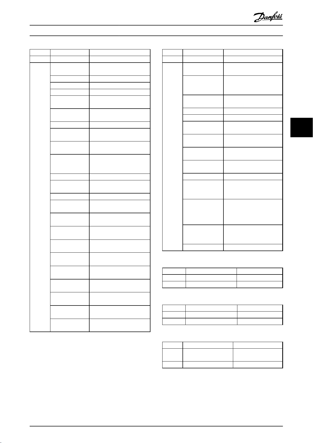
Parameter 300 Terminal 16, input 5-16 Terminal X30/2
Options [0] No function [0] No function
Comments FC 300 does not have a digital input 16, so this is
Table 5.87 Conversion of Parameter 300
Parameter 301 Terminal 17, input 5-17 Terminal X30/3
Options [0] No function [0] No operation
VLT 5000 series FC 302 series
Digital Input
[1] Reset [1] Reset
[2] Stop inverse [6] Stop inverse
[3] Only start clockwise,on[12] Enable start forward
[4] Jog [14] Jog
[5] Preset reference, on [15] Preset reference, on
[6] Preset reference, lsb [16] Preset reference bit
0
[7] Freeze reference [17] Freeze reference
[8] Freeze output [20] Freeze output
[9] Speed up [21] Speed up
[10] Choice of setup, lsb [23] Setup select bit 0
[11] Catch-up [28] Catch-up
[12] Ramp 2 [34] Ramp bit 0
[13] Mains failure inverted Not supported
[29] Data change lock Not supported
linked to 5-16 Terminal X30/2 Digital Input
VLT 5000 series FC 302 series
Digital Input
[1] Reset [1] Reset
[2] Stop inverse [6] Stop inverse
[3] Only start anticlockwise,on[13] Enable start reverse
Parameter 302 Terminal 18, input 5-10 Terminal 18 Digital
Options [0] No function [0] No operation
Table 5.89 Conversion of Parameter 302
Parameter 303 Terminal 19, input 5-11 Terminal 19 Digital
Options [0] No function [0] No operation
Table 5.90 Conversion of Parameter 303
Parameter 304 Terminal 27, input 5-12 Terminal 27 Digital
Options [0] Coasting stop,
Table 5.91 Conversion of Parameter 304
VLT 5000 series FC 302 series
Input
[1] Start [8] Start
[2] Latched start [9] Latched start
[3] Only start clockwise,on[12] Enable start forward
VLT 5000 series FC 302 series
Input
[1] Reversing [10] Reversing
[2] Start reversing [11] Start reversing
[3] Only start
anticlockwise, on
VLT 5000 series FC 302 series
inverse
[1] Reset and Coasting
stop, inv.
[2] Quick-stop, inverse [4] Quick-stop, inverse
[3] DC-braking, inverse [5] DC-brake inverse
[4] Stop inverse [6] Stop inverse
[13] Enable start reverse
Input
[2] Coast inverse
[3] Coast and reset inv
5 5
[4] Jog [14] Jog
[5] Preset reference, on [15] Preset reference,
on
[6] Preset reference, msb [17] Preset reference bit
1
[7] Freeze reference [19] Freeze reference
[8] Freeze output [20] Freeze output
[9] Speed down [22] Speed down
[10] Choice of setup, msb [24] Setup select bit 1
[11] Slow down [29] Slow down
[12] Ramp 2 [34] Ramp bit 0
[13] Mains failure inverted Not supported
[23] Pulse reference [32] Pulse input
[24] Safety interlock Not supported
[29] Data change lock Not supported
Comments FC 300 does not have a digital input 17, so this is
linked to 5-16 Terminal X30/2 Digital Input
Table 5.88 Conversion of Parameter 301
MG34N202 - Rev. 2013-10-15 21
Page 24

Parameter Mapping Lists
VLT® AutomationDrive FC 302 PROFIBUS Converter Operating Instructions
Parameter 305 Terminal 29, input 5-13 Terminal 29 Digital
Options [0] No function [0] No operation
55
Table 5.92 Conversion of Parameter 305
Parameter 306 Terminal 32, input 5-14 Terminal 32 Digital
Options [0] No function [0] No operation
VLT 5000 series FC 302 series
Input
[1] Reset [1] Reset
[2] Stop inverse [6] Stop inverse
[3] Only start clockwise,on[12] Enable start forward
[4] Only start
anticlockwise, on
[5] Jog [14] Jog
[6] Preset reference, on [15] Preset reference, on
[7] Preset reference, lsb [16] Preset reference bit 0
[8] Preset reference, msb [17] Preset reference bit 1
[9] Freeze reference [19] Freeze reference
[10] Freeze output [20] Freeze output
[11] Speed up [21] Speed up
[12] Speed down [22] Speed down
[13] Choice of Setup, lsb [23] Setup select bit 0
[14] Choice of Setup, msb [24] Setup select bit 1
[15] Catch up [28] Catch up
[16] Slow down [29] Slow down
[17] Ramp 2 [34] Ramp bit 0
[18] Mains failure inverted Not supported
[28] Pulse reference [32] Pulse input
[29] Data change lock Not supported
VLT 5000 series FC 302 series
[1] Reset [1] Reset
[2] Stop inverse [6] Stop inverse
[3] Only start clockwise,on[12] Enable start forward
[13] Enable start reverse
Input
Parameter 307 Terminal 33, input 5-15 Terminal 33 Digital
Options [0] No function [0] No operation
Table 5.94 Conversion of Parameter 307
VLT 5000 series FC 302 series
Input
7-00 Speed PID Feedback
Source
[1] Reset [1] Reset
[2] Stop inverse [6] Stop inverse
[3] Only start
anticlockwise, on
[4] Jog [14] Jog
[5] Preset reference, on [15] Preset reference, on
[6] Preset reference, msb [17] Preset reference bit 1
[7] Freeze reference [19] Freeze reference
[8] Freeze output [20] Freeze output
[9] Speed down [22] Speed down
[10] Choice of Setup,
msb
[11] Choice of Setup,
msb / Speed down
[12] Slow down [29] Slow down
[13] Ramp 2 [34] Ramp bit 0
[14] Mains failure
inverted
[24] Pulse feedback [32] Pulse input,
[25] Encoder input 2B [0] No operation
[29] Data change lock Not supported
[13] Enable start reverse
[24] Setup select bit 1
Not supported
Not supported
Parameter 700 = [9]
Frequency input 33
Parameter 700 = [1] 24 V
encoder
[4] Jog [14] Jog
[5] Preset reference, on [15] Preset reference, on
[6] Preset reference, lsb [16] Preset reference bit 0
[7] Freeze reference [19] Freeze reference
[8] Freeze output [20] Freeze output
[9] Speed up [21] Speed up
[10] Choice of Setup, lsb [23] Setup select bit 0
[11] Choice of Setup,
msb / Speed up
[12] Catch up [28] Catch up
[13] Ramp 2 [34] Ramp bit 0
[14] Mains failure
inverted
[24] Encoder input 2A [0] No operation
[29] Data change lock Not supported
Table 5.93 Conversion of Parameter 306
22 MG34N202 - Rev. 2013-10-15
Not supported
Not supported
Page 25

Parameter Mapping Lists
VLT® AutomationDrive FC 302 PROFIBUS Converter Operating Instructions
Parameter 308 Terminal
Options [0] No
Table 5.95 Conversion of Parameter 308
Parameter 309 Terminal 53, min.
Range 0 – 10.0 Volt -10.00 – Par. 6-11
Table 5.96 Conversion of Parameter 309
Parameter 310 Terminal 53, max.
Range 0 – 10.0 Volt Par. 6-10 - 10.00 Volt
Table 5.97 Conversion of Parameter 310
VLT 5000
series
53, Analogue
Input Voltage
Operation
[1] Reference Par. 3-15 Reference resource 1 set to
[2] Feedback
signal
[3] Torque
limit
[4] Thermistor Par. 3-15 Reference resource 1 set to
VLT 5000 series FC 302 series
scaling
VLT 5000 series FC 302 series
scaling
FC 302 series
3-15 Reference Resource 1
7-00 Speed PID Feedback Source
1-93 Thermistor Resource
4-20 Torque Limit Factor Source
Par. 3-15 Reference resource 1 set to
[0] No function
[1] Analog input 53
Par. 3-15 Reference resource 1 set to
[1] Analog input 53
Par. 7-00 Speed PID Feedback
Source set to [6] Analog input 53
Par. 3-15 Reference resource 1 set to
[1] Analog input 53
Par. 4-20 Torque Limit Factor Source
set to [2] Analog in 53
[0] No function
Par. 1-93 Thermistor Ressource set to
[1] Analog input 53
6-10 Terminal 53 Low
Voltage
6-11 Terminal 53 High
Voltage
Parameter 311 Terminal 54,
Options [0] No Operation Par. 3-16 Reference
Table 5.98 Conversion of Parameter 311
Parameter 312 Terminal 54, min.
Range 0 – 10.0 Volt -10.00 – Par. 6-21
Table 5.99 Conversion of Parameter 312
VLT 5000 series FC 302 series
scaling
VLT 5000 series FC 302 series
3-16 Reference
Analogue Input
Voltage
[1] Reference Par. 3-16 Reference
[2] Torque limit Par. 4-20 Torque
[3] Thermistor Par. 1-93 Thermistor
[4] Relative
reference
[5] Max. torque
frequency
Resource 2
7-00 Speed PID
Feedback Source
4-20 Torque Limit
Factor Source
1-93 Thermistor
Resource
4-21 Speed Limit
Factor Source
resource 2 set to [0]
No function
resource 1 set to [2]
Analog input 53
Limit Factor Source
set to [6] Analog in
54
Ressource set to [2]
Analog input 54
Not supported
Par. 4-21 Speed
Limit Factor Source
set to [6] Analog in
54
6-20 Terminal 54 Low
Voltage
5 5
Parameter 313 Terminal 54, max.
Range 0 – 10.0 Volt Par. 6-20 - 10.00 Volt
Table 5.100 Conversion of Parameter 313
MG34N202 - Rev. 2013-10-15 23
VLT 5000 series FC 302 series
6-21 Terminal 54 High
scaling
Voltage
Page 26
Parameter Mapping Lists
VLT® AutomationDrive FC 302 PROFIBUS Converter Operating Instructions
Parameter 314 Terminal 60,
Options [0] No Operation Par. 3-17 Reference resource 3 set
55
Comments The HW switch S202 for analogue input 54 must be
Table 5.101 Conversion of Parameter 314
Parameter 315 Terminal 60, min.
Range 0.0 – 20.0 mA 0.00 – Par. 6-23
Table 5.102 Conversion of Parameter 315
Parameter 316 Terminal 60, max.
Range 0.0 – 20.0 mA Par. 6-22 - 20.00 mA
Table 5.103 Conversion of Parameter 316
Parameter 317 Time Out 6-00 Live Zero Timeout Time
Range 0 – 99 sec 0 – 99 sec
Table 5.104 Conversion of Parameter 317
VLT 5000 series FC 302 series
3-17 Reference Resource 3
Analogue Input
current
[1] Reference Par. 3-17 Reference resource 3 set
[2] Feedback
signal
[3] Torque limit Par. 3-17 Reference resource 3 set
[4] Relative
reference
set to current (ON).
VLT 5000 series FC 302 series
scaling
VLT 5000 series FC 302 series
scaling
VLT 5000 series FC 302 series
7-00 Speed PID Feedback Source
1-93 Thermistor Resource
4-20 Torque Limit Factor Source
to [0] No function
to [2] Analog input 54 Par. 7-00
Speed PID
Feedback Source set to [7]
Analog input 54
Par. 7-00 Speed PID Feedback
Source set to [7] Analog input 54
to [2] Analog input 54 Par. 4-20
Torque Limit
Factor Source set to [6] Analog in
54
Not supported
6-22 Terminal 54 Low
Current
6-23 Teminal 54 High
Current
Parameter 318 Function after time
Options [0] Off [0] Off
Table 5.105 Conversion of Parameter 318
Parameter 319 Terminal 42,
Parameter 321 Terminal 45,
Options [0] No function Par. 5-32 = [0] No operation
VLT 5000 series FC 302 series
6-01 Live Zero Timeout
out
[1] Freeze output
frequency
[2] Stop [2] Stop
[3] Jogging [3] Jog
[4] Max Speed, p202 [4] Max Speed
[5] Stop and trip [5] Stop and trip
VLT 5000 series FC 302 series
Output
Output
[1] Control Ready Par. 5-32 = [1] Control Ready
[2] Ready signal Par. 5-32 = [2] Drive ready
[3] Ready - Remote
Control
[4] Enabled, no
warning
[5] Running
[6] Running, no
Warning
[7] Running within
range, no Warning
[8] Run at
reference, no
Warning
[9] Alarm Par. 5-32 = [9] Alarm
[10] Alarm or
Warning
[11] Torque limit Par. 5-32 = [11] At torque limit
[12] Out of current
range
[13] Above I low Par. 5-32 = [13] Below current,
[14] Under I high Par. 5-32 = [14] Above current,
Function
[1] Freeze output
frequency
Digital = Par. 5-32 DO X30/7
(MCB 101)
Analogue values = Par. 6-50 AO
42
Pulse = Par. 5-66 DO X30/6
Digital = Par. 5-33 DO X30/7
(MCB 101)
Analogue values= Par. 6-60 AO
X30/8
Pulse = Par. 5-66 DO X30/6
Par. 5-32 = [3] Drive rdy/rem
ctrl
Par. 5-32 = [4] Enable / no
warning
Par. 5-32 = [5] VLT® running
Par. 5-32 = [6] Running /no
warning
Par. 5-32 = [7] Run in range/no
warning
Par. 5-32 = [8] Run on ref/no
warning
Par. 5-32 = [10] Alarm or
Warning
Par. 5-32 = [12] Out of current
range
1)
low
1)
high
Table 5.106 Conversion of Parameters 319 to 321
24 MG34N202 - Rev. 2013-10-15
Page 27
Parameter Mapping Lists
VLT® AutomationDrive FC 302 PROFIBUS Converter Operating Instructions
Parameter 319 Terminal 42,
Parameter 321 Terminal 45,
Options [15] Out of
Table 5.107 Conversion of Parameters 319 to 321
VLT 5000 series FC 302 series
Digital = Par. 5-32 DO X30/7
Output
Output
frequency range
[16] Over f low Par. 5-32 = [16] Below speed
[17] Under f high Par. 5-32 = [17] Above speed
[18] Out of feedback
range
[19] Over feedback
low
[20] Under feedback
high
[21] Thermal
warning
[22] Ready, no
thermal warning
[23] Ready - remote
control - no thermal
warning
[24] Ready – mains
voltage within range
[25] Reversing Par. 5-32 = [25] Reverse
[26] Bus OK Par. 5-32 = [26] Bus OK
[27] Torque limit and
stop
(MCB 101)
Analogue values= Par. 6-50 AO
42
Pulse = Par. 5-66 DO X30/6
Digital = Par. 5-33 DO X30/7
(MCB 101)
Analogue values= Par. 6-60 AO
X30/8
Pulse = Par. 5-66 DO X30/6
Par. 5-32 = [15] Out of speed
range
1)
low
1)
high
Par. 5-32 = [18] Out of feedb.
Range
Par. 5-32 = [19] Below
feedback low
Par. 5-32 = [20] Above
feedback high
Par. 5-32 = [21] Thermal
warning
Par. 5-32 = [12] Ready,no
thermal W
Par. 5-32 = [23] Remote, ready,
no TW
Par. 5-32 = [24] Ready, Voltage
OK
Par. 5-32 = [27] Torque limit &
stop
Parameter 319 Terminal 42, Output Digital = Par. 5-32 DO
Parameter 321 Terminal 45, Output Digital = Par. 5-33 DO
Options [28] Brake, no brake
1)
1)
VLT 5000 series FC 302 series
X30/7 (MCB 101)
Analogue values= Par. 6-50
AO 42
Pulse = Par. 5-66 DO X30/6
X30/7 (MCB 101)
Analogue values= Par. 6-60
AO X30/8
Pulse = Par. 5-66 DO X30/6
Par. 5-32 = [28] Brake, no
warning
[29] Brake ready, no
fault
[30] Brake fault Par. 5-32 = [30] Brake fault
[31] Relay 123 Par. 5-32 = [31] Relay 123
[32] Mechanical brake
control
[34] Extended
mechanical brake
control
[35] Safety Interlock Not supported
[36] 0 – 100 Hz ⇒ 0 – 20
mA
[37] 0 – 100 Hz ⇒ 4 – 20
mA
[38] 0 – 100 Hz ⇒ 0 –
32000 p
[39] 0 – f max ⇒ 0 – 20
mA
[40] 0 – f max ⇒ 4 – 20
mA
[41] 0 – f max ⇒ 0 –
32000 p
[42] Ref min – Ref max
⇒ 0 – 20 mA
brake warning
Par. 5-32 = [29] Brake
ready, no fault
(IGBT)
Par. 5-32 = [32] Mech
brake ctrl
Par. 5-32 = [32] Mech
brake ctrl
Not supported
Not supported
Not supported
Par. 6-50 = [109] Max Out
freq. 0 – 20 mA
Par. 6-50 = [130] Max Out
freq. 4 – 20 mA
Par. 5-66 = [109] Max Out
freq. 0 – 32000p Par. 568 =
32000
Par. 6-50 = [101] Reference
0 -20 mA
5 5
Table 5.108 Conversion of Parameters 319 to 321
MG34N202 - Rev. 2013-10-15 25
Page 28

Parameter Mapping Lists
VLT® AutomationDrive FC 302 PROFIBUS Converter Operating Instructions
Parameter 319 Terminal 42,
Parameter 321 Terminal 45,
Options [43] Ref min – Ref max
55
VLT 5000 series FC 302 series
Digital = Par. 5-32 DO X30/7
Output
Output
⇒ 4 – 20 mA
[44] Ref min – Ref max
⇒ 0 - 32000 p
[45] FB min – FB max
⇒ 0 – 20 mA
[46] FB min – FB max
⇒ 4 – 20 mA
[47] FB min – FB max
⇒ 0 - 32000 p
[48] 0 – I max ⇒ 0 – 20
mA
[49] 0 – I max ⇒ 4 – 20
mA
[50] 0 – I max ⇒ 0 –
32000 p
[51] 0 – T lim ⇒ 0 – 20
mA
[52] 0 – T lim ⇒ 4 – 20
mA
[53] 0 – T lim ⇒ 0 –
32000 p
[54] 0 – T nom ⇒ 0 –
20 mA
[55] 0 – T nom ⇒ 4 –
20 mA
[56] 0 – T nom ⇒ 0 –
32000 p
[57] 0 – P nom ⇒ 0 –
20 mA
[58] 0 – P nom ⇒ 4 –
20 mA
[59] 0 – P nom ⇒ 0 –
32000 p
(MCB 101)
Analogue values= Par. 6-50
AO 42
Pulse = Par. 5-66 DO X30/6
Digital = Par. 5-33 DO X30/7
(MCB 101)
Analogue values= Par. 6-60
AO X30/8
Pulse = Par. 5-66 DO X30/6
Par. 6-50 = [131] Reference
4 -20 mA
Par. 5-66 = [101] Reference
0 – 32000p Par. 5-68 =
32000
Par. 6-50 = [102] Feedback 0
-20 mA
Par. 6-50 = [132] Feedback 4
-20 mA
Par. 5-66 = [102] Feedback 0
– 32000p Par. 5-68 = 32000
Par. 6-50 = [103] Motor
current 0 -20 mA
Par. 6-50 = [133] Motor
current 4 -20 mA
Par. 5-66 = [103] Motor
current 0 - 32000p Par. 5-68
= 32000
Par. 6-50 = [104] Torque
related to limit 0 - 20 mA
Par. 6-50 = [134] Torque
related to limit 4 - 20 mA
Par. 5-66 = [104] Torque
related to limit 0 – 32000p
Par. 5-68 = 32000
Par. 6-50 = [105] Torque
related to norm 0 - 20 mA
Par. 6-50 = [135] Torque
related to norm 4 - 20 mA
Par. 5-66 = [105] Torque
related to norm 0 – 32000p
Par. 5-68 = 32000
Par. 6-50 = [106] Power
related to norm 0 - 20 mA
Par. 6-50 = [136] Power
related to norm 4 - 20 mA
Par. 5-66 = [106] Power
related to norm 0 – 32000p
Par. 5-68 = 32000
Parameter 319 Terminal 42,
Parameter 321 Terminal 45,
Options
Table 5.110 Conversion of Parameters 319 to 321
Parameter 320 Terminal 42 Output,
Range 1 – 32000 Hz 0 – 32000 Hz
Table 5.111 Conversion of Parameter 320
Parameter 322 Terminal 45 Output,
Range 1 – 32000 Hz 0– 32000 Hz
Table 5.112 Conversion of Parameter 322
VLT 5000 series FC 302 series
Digital = Par. 5-32 DO X30/7
Output
Output
[60] 0 – SyncRPM ⇒ 0
– 20 mA
[61] 0 – SyncRPM ⇒ 4
– 20 mA
[62] 0 – SyncRPM ⇒ 0
– 32000 p
[63] RPM at F max ⇒ 0
– 20 mA
[64] RPM at F max ⇒ 4
– 20 mA
[65] RPM at F max ⇒ 0
– 32000 p
VLT 5000 series FC 302 series
pulse scaling
VLT 5000 series FC 302 series
pulse scaling
(MCB 101)
Analogue values= Par. 6-50
AO 42
Pulse = Par. 5-66 DO X30/6
Digital = Par. 5-33 DO X30/7
(MCB 101)
Analogue values= Par. 6-60
AO X30/8
Pulse = Par. 5-66 DO X30/6
Not supported
Not supported
Not supported
Par. 6-50 = [107] Speed
related to norm 0 - 20 mA
Par. 6-50 = [137] Speed
related to norm 4 - 20 mA
Par. 5-66 = [107] Speed
related to norm 0 – 32000p
Par. 5-68 = 32000
5-68 Pulse Output Max
Freq #X30/6
5-68 Pulse Output Max
Freq #X30/6
Table 5.109 Conversion of Parameters 319 to 321
26 MG34N202 - Rev. 2013-10-15
Page 29
Parameter Mapping Lists
VLT® AutomationDrive FC 302 PROFIBUS Converter Operating Instructions
VLT 5000 series FC 302 series
Parameter 323, 326 5-40 Function Relay
Range 01 Relay
04 Relay
Relay 1
Relay 2
[0] No function Par. 5-40 = [0] No operation
[1] Control Ready Par. 5-40 = [1] Control Ready
[2] Ready signal Par. 5-40 = [2] Drive ready
[3] Ready - Remote
Control
[4] Enabled, no
warning
Par. 5-40 = [3] Drive rdy/rem
ctrl
Par. 5-40 = [4] Enable / no
warning
[5] Running Par. 5-40 = [5] VLT running
[6] Running, no
Warning
[7] Running within
range, no warning
[8] Run at
reference, no
Par. 5-40 = [6] Running / no
warning
Par. 5-40 = [7] Run in range/no
warn
Par. 5-40 = [8] Run on ref/no
warn
Warning
[9] Alarm Par. 5-40 = [9] Alarm
[10] Alarm or
Warning
Par. 5-40 = [10] Alarm or
Warning
[11] Torque limit Par. 5-40 = [11] At torque limit
[12] Out of current
range
Par. 5-40 = [12] Out of current
range
[13] Above I low Par. 5-40 = [13] Below current,
1)
low
[14] Under I high Par. 5-40 = [14] Above current,
1)
high
[15] Out of
frequency range
Par. 5-40 = [15] Out of speed
range
[16] Over f low Par. 5-40 = [16] Below speed
1)
low
[17] Under f high Par.5-40 = [17] Above speed
1)
high
[18] Out of
feedback range
[19] Over feedback
low
[20] Under feedback
high
[21] Thermal
warning
Par. 5-40 = [18] Out of feedb.
Range
Par. 5-40 = [16] Below feedback
1)
low
Par. 5-40 = [17] Above feedback
1)
high
Par. 5-40 = [21] Thermal
warning
Table 5.113 Conversion of Parameters 323 to 326
VLT 5000 series FC 302 series
Parameter 323, 326 5-40 Function Relay
Range [22] Ready, no
thermal warning
[23] Ready - remote
control - no thermal
Par. 5-40 = [12] Ready,no
thermal W
Par. 5-40 = [23] Remote, ready,
no TW
warning
[24] Ready – mains
voltage within range
Par. 5-40 = [24] Ready, Voltage
OK
[25] Reversing Par. 5-40 = [25] Reverse
[26] Bus OK Par. 5-40 = [26] Bus OK
[27] Torque limit and
stop
[28] Brake, no brake
warning
[29] Brake ready, no
fault
Par. 5-40 = [27] Torque limit &
stop
Par. 5-40 = [28] Brake, no
brake warning
Par. 5-40 = [29] Brake ready,
no fault
[30] Brake fault Par. 5-40 = [30] Brake fault
(IGBT)
[31] Relay 123 Par. 5-40 = [31] Relay 123
[32] Mechanical
brake control
Par. 5-40.0 = [32] Mech brake
ctrl
Par. 1-72 = [5] VVC+/Flux
[33] Control word bit
11/12
Par. 5-40 = [36] Control word
bit 11
Par. 5-40.1 = [37] Control word
bit 12
[34] Extended
mechanical brake
control
Par. 5-40.0 = [32] Mech brake
ctrl
Par. 1-72 = [5] VVC+/Flux
[35] Safety Interlock Not supported
Table 5.114 Conversion of Parameters 323 to 326
VLT 5000 series FC 302 series
Parameter 324 Relay 01, ON delay 5-41 On Delay, Relay
Range 0.00 – 600.00 sec 0.01 – 600.00 sec
Table 5.115 Conversion of Parameter 324
VLT 5000 series FC 302 series
Parameter 325 Relay 01, OFF delay 5-42 Off Delay, Relay
Range 0.00 – 600.00 s 0.01 – 600.00 s
Table 5.116 Conversion of Parameter 325
Parameter 327 Pulse reference, max.
VLT 5000 series FC 302 series
5-51 Term. 29 High
freq
Frequency
Range 100 – 65000 Hz 0 – 110000 Hz
5 5
Table 5.117 Conversion of Parameter 327
MG34N202 - Rev. 2013-10-15 27
Page 30
Parameter Mapping Lists
VLT® AutomationDrive FC 302 PROFIBUS Converter Operating Instructions
Parameter 328 Pulse feedback, max. freq 5-56, 5-50, 5-55
Range 100 – 65000 Hz 0 – 110000 Hz
Table 5.118 Conversion of Parameter 328
Parameter 329 Encoder feedback
Range 1 – 4096 pulses 1 – 4096 pulses
Table 5.119 Conversion of Parameter 329
55
Parameter 330 Freeze ref. /output function Not converted
Table 5.120 Conversion of Parameter 330
Parameter 345 Encoder loss
Range 0.0 – 60.0 s 0.00 – 60.00 s
Table 5.121 Conversion of Parameter 345
VLT 5000 series FC 302 series
VLT 5000 series FC 302 series
5-70 Term 32/33 Pulses
pulse/rev.
VLT 5000 series FC 302 series
VLT 5000 series FC 302 series
timeout
Per Revolution
4-32 Motor Feedback Loss
Timeout
Parameter 360 Term. 45, Output
Range 0 – 500% 0 – 200%
Table 5.126 Conversion of Parameter 360
Parameter 361 Encoder loss threshold Not converted
Range 0 – 600%
Table 5.127 Conversion of Parameter 361
VLT 5000 series FC 302 series
6-62 Terminal X30/8 Max.
max. scale
VLT 5000 series FC 302 series
Scale
Parameter 346 Encoder loss
Range [0] Off [0] Disable
Table 5.122 Conversion of Parameter 346
Parameter 357 Term. 42, Output
Range 0 – 100% 0 – 200%
Table 5.123 Conversion of Parameter 357
Parameter 358 Term. 42, Output
Range 0 – 500% 0 – 200%
VLT 5000 series FC 302 series
4-30 Motor Feedback Loss
function
[1] Freeze output
frequency
[3] Jog [3] Jog
[4] Max speed [5] Max speed
[5] Stop and trip [11] Stop and trip
[7] Select setup 4 [10] Select setup 4
VLT 5000 series FC 302 series
min. scale
VLT 5000 series FC 302 series
max. scale
Function
[4] Freeze output
frequency
6-51 Terminal 42 Output
Min Scale
6-52 Terminal 42 Output
Max Scale
Table 5.124 Conversion of Parameter 358
Parameter 359 Term. 45, Output
Range 0 – 100% 0 – 200%
Table 5.125 Conversion of Parameter 359
28 MG34N202 - Rev. 2013-10-15
VLT 5000 series FC 302 series
6-61 Terminal X30/8 Min.
min. scale
Scale
Page 31
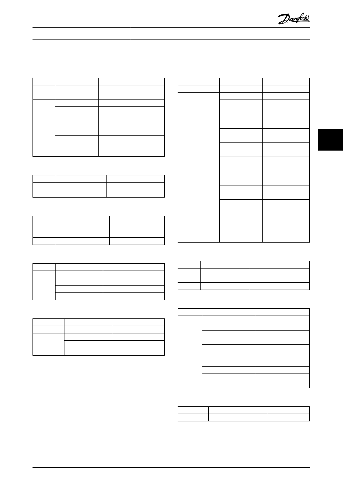
Parameter Mapping Lists
5.5
VLT® 5000 Parameter Group 4
VLT® AutomationDrive FC 302 PROFIBUS Converter Operating Instructions
Parameter 400 Brake function/
Options [0] Off [0] Off
Table 5.128 Conversion of Parameter 400
Parameter
Options Power unit dependable Power unit dependable
Table 5.129 Conversion of Parameter 401
Parameter 402 Brake power limit,
Range Depends on unit Depends on unit
VLT 5000 series FC 302 series
2-10 Brake Function
over voltage cont.
[1] Resistor brake Par. 2-10 = *1* Resistor brake
[2] Over voltage
control
[3] Over voltage
control and stop
VLT 5000 series FC 302 series
401 Brake resistor, [Ω]
VLT 5000 series FC 302 series
[kW]
2-17 Over-voltage Control
Par. 2-17 = [0] Off
Par. 2-10 = [0] Off
Par. 2-17 = [2] Enabled
Par- 2-10 = [0] Off
Par. 2-17 = [1] Enabled (not at
stop)
30-81 Brake Resistor (ohm)
2-12 Brake Power Limit
(kW)
Parameter 405 Reset 14-20 Reset Mode
Options [0] Manual reset [0] Off
VLT 5000 series FC 302 series
[1] Automatic reset
x 1
[2] Automatic reset
x 2
[3] Automatic reset
x 3
[4] Automatic reset
x 4
[5] Automatic reset
x 5
[6] Automatic reset
x 6
[7] Automatic reset
x 7
[8] Automatic reset
x 8
[9] Automatic reset
x 9
[10] Automatic reset
x 10
[1] Automatic reset x
1
[2] Automatic reset x
2
[3] Automatic reset x
3
[4] Automatic reset x
4
[5] Automatic reset x
5
[6] Automatic reset x
6
[7] Automatic reset x
7
[8] Automatic reset x
8
[9] Automatic reset x
9
[10] Automatic reset x
10
5 5
Table 5.130 Conversion of Parameter 402
Parameter 403 Power monitoring 2-13 Brake Power Monitoring
Options [0] Off [0] Off
Table 5.131 Conversion of Parameter 403
Parameter 404 Brake check 2-15 Brake Check
Options [0] Off [0] Off
Table 5.132 Conversion of Parameter 404
VLT 5000 series FC 302 series
[1] Warning [1] Warning
[2] Trip [2] Trip
VLT 5000 series FC 302 series
[1] Warning [1] Warning
[2] Trip [2] Trip
Table 5.133 Conversion of Parameter 405
Parameter 406 Automatic restart
Range 0 – 10 s 0 – 600 s
Table 5.134 Conversion of Parameter 406
Parameter 407 Mains failure 14-10 Mains Failure
Data range [0] No function [0] No function
Table 5.135 Conversion of Parameter 407
Parameter 408 Quick discharge Not converted
VLT 5000 series FC 302 series
14-21 Automatic Restart
time
5000 series FC 302 series
[1] Controlled ramp
down
[2] Controlled ramp
down and trip
[3] Coast [3] Coast
[4] Kinetic back-up [4] Kinetic back-up
[5] Controlled alarm
suppression
VLT 5000 series FC 302 series
Time
[1] Controlled ramp down
[2] Controlled ramp down
and trip
[5] Kinetic back-up, trip
Table 5.136 Conversion of Parameter 408
MG34N202 - Rev. 2013-10-15 29
Page 32
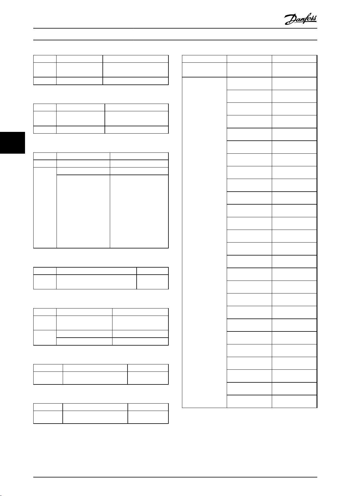
Parameter Mapping Lists
VLT® AutomationDrive FC 302 PROFIBUS Converter Operating Instructions
Parameter 409 Trip delay torque 14-25 Trip Delay at Torque
Range 0 – 60 s (60=OFF) 0 – 60 s (60=OFF)
Table 5.137 Conversion of Parameter 409
Parameter 410 Trip delay inverter 14-26 Trip Delay at Inverter
Range 0 – 35 s 0 – 35 s
55
Table 5.138 Conversion of Parameter 410
Parameter 411 Switching frequency 14-01 Switching Frequency
Range Unsigned 16 (6) Unsigned 8 (5)
Table 5.139 Conversion of Parameter 411
Parameter 412 Output frequency dependent
VLT 5000 series FC 302 series
Limit
VLT 5000 series FC 302 series
Fault
VLT 5000 series FC 302 series
1.5 – 14 kHz
VLT 5000 series FC 302 series
switching frequency
< 2.3 ⇒ 2.0 kHz [2]
2.3 > 2.7 ⇒ 2.5 kHz [3]
2.8 > 3.2 ⇒ 3.0 kHz [4]
3.3 > 3.7 ⇒ 3.5 kHz [5]
3.8 > 4.5 ⇒ 4.0 kHz [6]
4.6 > 5.5 ⇒ 5.0 kHz [7]
5.6 > 6.5 ⇒ 6.0 kHz [8]
6.6 > 7.5 ⇒ 7.0 kHz [9]
7.6 > 9.0 ⇒ 8.0 kHz [10]
9.1 > ⇒ 10.0 kHz [11]
Not converted
Parameter 416 Feedback Unit 3-01 Reference/
Options
VLT 5000 series FC 302 series
feedback Unit
[0] None [0] None
[1] % [1] %
[2] PPM [5] PPM
[3] rpm [2] RPM
[4] bar [71] bar
[5] Cycle/min Not supported
[6] Pulse/s [12] Pulse/s
[7] Unit s/s Not supported
[8] Unit s/min Not supported
[9] Unit s/h Not supported
[10] °C [60] °C
[11] Pa [72] Pa
[12] l/s [20] l/s
[13] m3/s [23] m3/s
[14] l/min [21] l/min
[15] m3/min [24] m3/min
[16] l/h [22] l/h
Table 5.140 Conversion of Parameter 412
Parameter 413 Overmodulation
Options [0] Off [0] Off
Table 5.141 Conversion of Parameter 413
Parameter 414 Minimum feedback Not converted
Table 5.142 Conversion of Parameter 414
Parameter 415 Maximum feedback Not converted
Table 5.143 Conversion of Parameter 415
VLT 5000 series FC 302 series
14-03 Overmodulation
function
[1] On [1] On
VLT 5000 series FC 302 series
VLT 5000 series FC 302 series
function
[17] m3/h [25] m3/h
[18] kg/s [30] kg/s
[19] kg/min [31] kg/min
[20] kg/h [32] kg/h
[21] t/min [33] t/min
[22] t/h [34] t/h
[23] m [45] m
[24] Nm [4] Nm
[25] m/s [40] m/s
Table 5.144 Conversion of Parameter 416 part 1
30 MG34N202 - Rev. 2013-10-15
Page 33
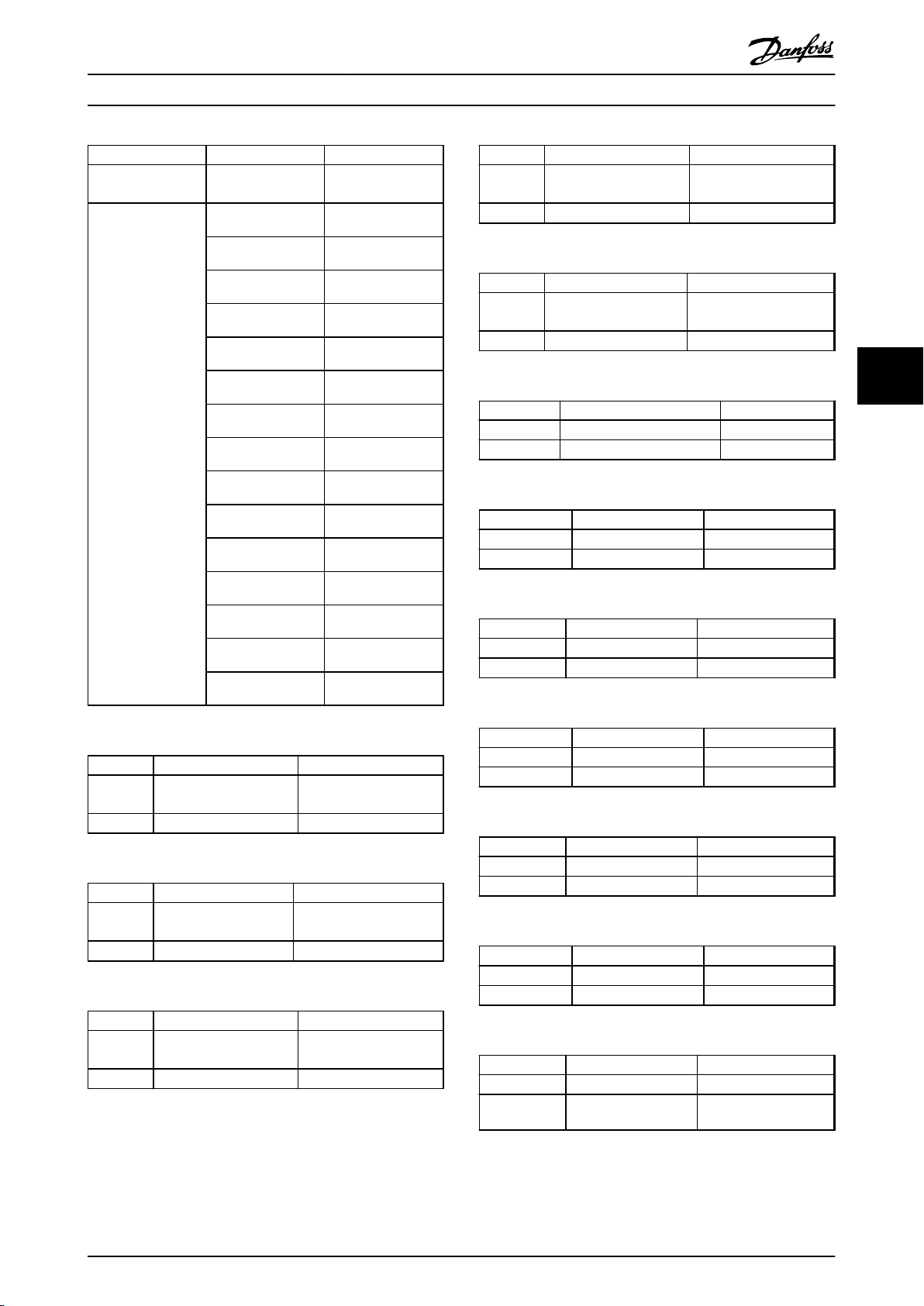
Parameter Mapping Lists
VLT® AutomationDrive FC 302 PROFIBUS Converter Operating Instructions
Parameter 416 Feedback Unit 3-01 Reference/
VLT 5000 series FC 302 series
feedback Unit
[26] m/min [41] m/min
[27] °F [160] °F
[28] in wg [172] in wg
[29] gal/s [121] gal/s
[30] ft3/s [125] ft3/s
[31] gal/min [122] gal/min
[32] ft3/min [126] ft3/min
[33] gal/h [123] gal/h
[34] ft3/h [127] ft3/h
[35] lb/s [130] lb/s
[36] lb/min [131] lb/min
[37] lb/h [132] lb/h
Parameter 420 Speed PID D-gain
Data range 5.0 – 50.0 1.0 – 20.0
Table 5.149 Conversion of Parameter 420
Parameter 421 Speed PID low-pass
Data range 5.0 – 200.0 ms 1.0 – 100.0
Table 5.150 Conversion of Parameter 421
Parameter 422 U0 voltage at 0 Hz 1-55 U0 voltage
Data range 0.0 – par. 103 0.0 – 1000.0 V
Table 5.151 Conversion of Parameter 422
Parameter 423 U1 voltage 1-55 U1 voltage
Data range 0.0 – par. 103 0.0 – 1000.0 V
Table 5.152 Conversion of Parameter 423
VLT 5000 series FC 302 series
7-05 Speed PID Diff. Gain
limit
VLT 5000 series FC 302 series
filter
VLT 5000 series FC 302 series
VLT 5000 series FC 302 series
Limit
7-06 Speed PID Lowpass
Filter Time
5 5
[38] lb ft [150] lb ft
[39] ft/s [140] ft/s
[40] ft/min [141] ft/min
Table 5.145 Conversion of Parameter 416 part2
Parameter 417 Speed PID propor-
Data range 0.000 – 0.150 0.000 – 1.000
Table 5.146 Conversion of Parameter 417
Parameter 418 Speed PID Integral
Data range 2.0 – 999.9 2.0 – 20000.0
Table 5.147 Conversion of Parameter 418
Parameter 419 Speed PID Differen-
Data range 0.0 – 200.0 0.0 – 200.0
Table 5.148 Conversion of Parameter 419
VLT 5000 series FC 302 series
7-02 Speed PID propor-
tional gain
VLT 5000 series FC 302 series
Time
VLT 5000 series FC 302 series
tiation Time
tional gain
7-03 Speed PID proportional gain
7-04 Speed PID Differentiation Time
Parameter 424 F1 frequency 1-56 F1 frequency
Data range 0.0 – par. 104 0.0 – 1000.0 Hz
Table 5.153 Conversion of Parameter 424
Parameter 425 U2 voltage 1-55 U2 voltage
Data range 0.0 – par. 103 0.0 – 1000.0 V
Table 5.154 Conversion of Parameter 425
Parameter 426 F2 frequency 1-56 F2 frequency
Data range 0.0 – par. 104 0.0 – 1000.0 Hz
Table 5.155 Conversion of Parameter 426
Parameter 427 U3 voltage 1-55 U3 voltage
Data range 0.0 – par. 103 0.0 – 1000.0 V
Table 5.156 Conversion of Parameter 427
Parameter 428 F3 frequency 1-56 F3 frequency
Data range 0.0 – par. 104 0.0 – 1000.0 Hz
VLT 5000 series FC 302 series
VLT 5000 series FC 302 series
VLT 5000 series FC 302 series
VLT 5000 series FC 302 series
VLT 5000 series FC 302 series
Table 5.157 Conversion of Parameter 428
MG34N202 - Rev. 2013-10-15 31
Page 34

Parameter Mapping Lists
VLT® AutomationDrive FC 302 PROFIBUS Converter Operating Instructions
Parameter 429 U4 voltage 1-55 U4 voltage
Data range 0.0 – par. 103 0.0 – 1000.0 V
Table 5.158 Conversion of Parameter 429
Parameter 430 F4 frequency 1-56 F4 frequency
Data range 0.0 – par. 104 0.0 – 1000.0 Hz
Table 5.159 Conversion of Parameter 430
VLT 5000 series FC 302 series
VLT 5000 series FC 302 series
55
Parameter 431 U5 voltage 1-55 U5 voltage
Data range 0.0 – par. 103 0.0 – 1000.0 V
Table 5.160 Conversion of Parameter 431
Parameter 432 F5 frequency 1-56 F5 frequency
Data range 0.0 – par. 104 0.0 – 1000.0 Hz
VLT 5000 series FC 302 series
VLT 5000 series FC 302 series
Parameter 438 Process PID Anti
Options [0] Off [0] Off
Table 5.165 Conversion of Parameter 438
Parameter 439 Process PID
Data range Fmin – fmax 0 – 6000 rpm
Table 5.166 Conversion of Parameter 439
Parameter 440 Process PID
Data range 0.00 – 10.00 0.00 – 10.00
Table 5.167 Conversion of Parameter 440
VLT 5000 series FC 302 series
7-31 Process PID
windup
[1] On [1] On
VLT 5000 series FC 302 series
start frequency
VLT 5000 series FC 302 series
proportional gain
Anti Windup
7-32 Process PID
Start Speed
7-33 Process PID
proportional gain
Table 5.161 Conversion of Parameter 432
Parameter 433 Torque control,
Data range 0 (Off) – 500% 0 (Off) – 500%
Table 5.162 Conversion of Parameter 433
Parameter 434 Torque control,
Data range 0.002 – 2.000 sec 0.002 – 2.000 sec
Table 5.163 Conversion of Parameter 434
Parameter 437 Process PID
Options [0] Normal [0] Normal
VLT 5000 series FC 302 series
7-12 Torque PI
open loop proportional gain
VLT 5000 series FC 302 series
open loop integral
time
VLT 5000 series FC 302 series
Normal/Inverse
contr
[1] Inverse [1] Inverse
Integration Time
7-13 Torque PI
Integration Time
7-30 Process PID
Normal/ Inverse
Control
Parameter 441 Process PID
Data range 0.01 – 9999.99 0.01 – 10000.00
Table 5.168 Conversion of Parameter 441
Parameter 442 Process PID
Data range 0.00 – 10.00 0.00 – 10.00
Table 5.169 Conversion of Parameter 442
Parameter 443 Process PID diff.
Data range 5.0 – 50.0 0.00 – 10.00
Table 5.170 Conversion of Parameter 443
Parameter 444 Process PID
VLT 5000 series FC 302 series
7-34 Process PID
integral time
VLT 5000 series FC 302 series
differentiation time
VLT 5000 series FC 302 series
gain limit
VLT 5000 series FC 302 series
lowpass filter time
integral time
7-35 Process PID
Differentiation Time
7-36 Process PID
Diff. Gain Limit
Not supported
Table 5.171 Conversion of Parameter 444
Table 5.164 Conversion of Parameter 437
32 MG34N202 - Rev. 2013-10-15
Page 35

Parameter Mapping Lists
VLT® AutomationDrive FC 302 PROFIBUS Converter Operating Instructions
Parameter 445 Flying start 1-73 Flying Start
Options [0] Off [0] Disable
Table 5.172 Conversion of Parameter 445
Parameter 446 Switching
Options [0] 60 AVM [0] 60 AVM
Table 5.173 Conversion of Parameter 446
Parameter 447 Torque
Table 5.174 Conversion of Parameter 447
VLT 5000 series FC 302 series
[1] On [1] Enable
VLT 5000 series FC 302 series
14-00 Switching
pattern
[1] SFAVM [1] SFAVM
VLT 5000 series FC 302 series
compensation
Pattern
Not supported
Parameter 455 Frequency
Table 5.180 Conversion of Parameter 455
Parameter 457 Phase loss
Options [0] Trip [0] Trip
Table 5.181 Conversion of Parameter 457
Parameter 483 Dynamic DC
Table 5.182 Conversion of Parameter 483
VLT 5000 series FC 302 series
Not supported
range monitor
VLT 5000 series FC 302 series
14-12 Function at
functions
[1] Warning [1] Warning
VLT 5000 series FC 302 series
link compensation
Mains Imbalance
Not supported
5 5
Parameter 448 Gear ratio Not supported
Table 5.175 Conversion of Parameter 448
Parameter 449 Friction loss Not supported
Table 5.176 Conversion of Parameter 449
Parameter 450 Mains voltage
Range 180 – 690 V 100 – 800 V
Table 5.177 Conversion of Parameter 450
Parameter 453 Gear ratio,
Range 0.01 – 100.00 0.0001 – 32.0000
VLT 5000 series FC 302 series
VLT 5000 series FC 302 series
VLT 5000 series FC 302 series
14-11 Mains Voltage
at mains fault
VLT 5000 series FC 302 series
speed close loop
at Mains Fault
7-07 Speed PID
Feedback Gear Ratio
Table 5.178 Conversion of Parameter 453
Parameter 454 Dead time
Table 5.179 Conversion of Parameter 454
VLT 5000 series FC 302 series
compensation
Not supported
MG34N202 - Rev. 2013-10-15 33
Page 36

Parameter Mapping Lists
5.6
VLT® 5000 Parameter Group 5
VLT® AutomationDrive FC 302 PROFIBUS Converter Operating Instructions
Parameter 500 Address 8-31 Address
Range 0 - 126 0 - 126
Table 5.183 Conversion of Parameter 500
Parameter 501 Baud rate 8-32 FC Port Baud Rate
Options [0] 300 Not supported
55
Table 5.184 Conversion of Parameter 501
Parameter 502 Coasting 8-50 Coasting Select
Parameter 503 Quick - Stop 8-51 Quick Stop Select
Parameter 504 DC brake 8-52 DC Brake Select
Parameter 505 Start 8-53 Start Select
Parameter 506 Reversing 8-54 Reversing Select
Parameter 507 Setup select 8-55 Set-up Select
Parameter 508 Preset reference
Parameter
type
Options [0] Digital input [0] Digital input
Table 5.185 Conversion of Parameter 502 - 508
Parameter 509 Bus Jog 1 8-90 Bus Jog 1 Speed
Range 0.0 – par. 202 0.0 – par. 4-13
Table 5.186 Conversion of Parameter 509
VLT 5000 series FC 302 series
VLT 5000 series FC 302 series
[1] 600 Not supported
[2] 1200 Not supported
[3] 2400 [0] 2400
[4] 4800 [1] 4800
[5] 9600 [2] 9600
VLT 5000 series FC 302 series
8-56 Preset Reference
select
Unsigned 8 (5) Unsigned 8 (5)
[1] Bus [1] Bus
[2] Logic AND [2] Logic AND
[3] Logic OR [3] Logic OR
VLT 5000 series FC 302 series
Select
Parameter 514 Bus time interval function Not Converted
Table 5.190 Conversion of Parameter 514
Parameter 515 Reference % 16-02 Reference %
Table 5.191 Conversion of Parameter 515
Parameter 516 Reference Unit 16-01 Reference [Unit]
Table 5.192 Conversion of Parameter 516
Parameter 517 Feedback 16-52 Feedback[Unit]
Table 5.193 Conversion of Parameter 517
Parameter 518 Frequency 16-13 Frequency
Table 5.194 Conversion of Parameter 518
Parameter 519 Frequency x scaling Not converted
Table 5.195 Conversion of Parameter 519
Parameter 520 Current 16-14 Motor current
Table 5.196 Conversion of Parameter 520
Parameter 521 Torque 16-22 Torque [%]
Table 5.197 Conversion of Parameter 521
Parameter 522 Power, kW 16-10 Power [kW]
VLT 5000 series FC 302 series
VLT 5000 series FC 302 series
VLT 5000 series FC 302 series
VLT 5000 series FC 302 series
VLT 5000 series FC 302 series
VLT 5000 series FC 302 series
VLT 5000 series FC 302 series
VLT 5000 series FC 302 series
16-21 Torque [%] high resolution
VLT 5000 series FC 302 series
Parameter 510 Bus Jog 2 8-91 Bus Jog 2 Speed
Range 0.0 – par. 202 0.0 – par. 4-13
Table 5.187 Conversion of Parameter 510
Parameter 512 Telegram Profile 8-10 Control Word Profile
Range [0] Fieldbus profile [1] ProfiDrive profile
Table 5.188 Conversion of Parameter 512
Parameter 513 Bus time interval Not Converted
Table 5.189 Conversion of Parameter 513
34 MG34N202 - Rev. 2013-10-15
VLT 5000 series FC 302 series
VLT 5000 series FC 302 series
[1] FC profile [0] FC profile
VLT 5000 series FC 302 series
Table 5.198 Conversion of Parameter 522
Parameter 523 Power, HP 16-11 Power [hp]
Table 5.199 Conversion of Parameter 523
Parameter 524 Motor voltage 16-12 Motor Voltage
Table 5.200 Conversion of Parameter 524
Parameter 525 DC link voltage 16-30 DC Link Voltage
Table 5.201 Conversion of Parameter 525
VLT 5000 series FC 302 series
VLT 5000 series FC 302 series
VLT 5000 series FC 302 series
Page 37

Parameter Mapping Lists
VLT® AutomationDrive FC 302 PROFIBUS Converter Operating Instructions
Parameter 526 Motor temp. 16-18 Motor Thermal
Table 5.202 Conversion of Parameter 526
Parameter
Table 5.203 Conversion of Parameter 527
Parameter 528 Digital input 16-60 Digital Input
Options Term. 16 (binary 0000 0001) Term. X30/2 (binary)
Table 5.204 Conversion of Parameter 528
Parameter 529 Analogue input 53 16-62 Analog Input 53
Table 5.205 Conversion of Parameter 529
* = Switch “S201” must be OFF
Parameter 530 Analogue input 54 16-64 Analog Input 54
Table 5.206 Conversion of Parameter 530
** = Switch “S202” must be OFF
Parameter 531 Analogue input 60 16-64 Analog Input 54
VLT 5000 series FC 302 series
VLT 5000 series FC 302 series
527 VLT® temp.
VLT 5000 series FC 302 series
Term. 17 (binary 0000 0010) Term. X30/3 (binary)
Term. 18 (binary 0000 0100) Term. 18 (binary)
Term. 19 (binary 0000 1000) Term. 19 (binary)
Term. 27 (binary 0001 0000) Term. 27 (binary)
Term. 32 (binary 0010 0000) Term. 32 (binary)
Term. 33 (binary 0100 0000) Term. 33 (binary)
VLT 5000 series FC 302 series
VLT 5000 series FC 302 series
VLT 5000 series FC 302 series
16-35 Inverter Thermal
Parameter 536 Brake power/s 16-32 Brake Energy /s
Table 5.212 Conversion of Parameter 536
Parameter 537 Heat sink temp 16-34 Heatsink Temp.
Table 5.213 Conversion of Parameter 537
Parameter 538 Alarm word 14-72 Legacy Alarm Word
Table 5.214 Conversion of Parameter 538
Parameter
Table 5.215 Conversion of Parameter 539
Parameter 540 Warning word 14-73 Legacy Warning Word
Table 5.216 Conversion of Parameter 540
Parameter 541 Extended status
Table 5.217 Conversion of Parameter 541
Parameter 553 Display text 1 Not converted
Table 5.218 Conversion of Parameter 553
VLT 5000 series FC 302 series
VLT 5000 series FC 302 series
VLT 5000 series FC 302 series
VLT 5000 series FC 302 series
539 VLT® Control word
VLT 5000 series FC 302 series
VLT 5000 series FC 302 series
word
VLT 5000 series FC 302 series
16-00 Control Word
14-74 Leg. Ext. Status
Word
5 5
Table 5.207 Conversion of Parameter 531
*** = Switch “S202” must be ON
Parameter 532 Pulse reference 16-51 Pulse Reference
Table 5.208 Conversion of Parameter 532
Parameter 533 External reference % 16-50 External Reference
Table 5.209 Conversion of Parameter 533
Parameter 534 Status word, binary 16-03 Status Word
Table 5.210 Conversion of Parameter 534
Parameter 535 Brake power/2 min 16-33 Brake Energy /2 min
Table 5.211 Conversion of Parameter 535
VLT 5000 series FC 302 series
VLT 5000 series FC 302 series
VLT 5000 series FC 302 series
VLT 5000 series FC 302 series
MG34N202 - Rev. 2013-10-15 35
Parameter 554 Display text 2 Not converted
Table 5.219 Conversion of Parameter 554
Parameter 557 Motor RPM 16-17 Speed [RPM]
Table 5.220 Conversion of Parameter 557
Parameter 558 Motor RPM x scaling Not converted
Table 5.221 Conversion of Parameter 558
Parameter
number
Table 5.222 Conversion of Parameter 580-582
VLT 5000 series FC 302 series
VLT 5000 series FC 302 series
VLT 5000 series FC 302 series
VLT 5000 series FC 302 series
580, 581, 582 Define
parameter
Not converted
Page 38

Parameter Mapping Lists
5.7
VLT® 5000 Parameter Group 6
VLT® AutomationDrive FC 302 PROFIBUS Converter Operating Instructions
Parameter 600 Operating hours 15-00 Operating hours
Table 5.223 Conversion of Parameter 600
Parameter 601 Hours run 15-01 Running Hours
55
Table 5.224 Conversion of Parameter 601
Parameter 602 kWh counter 15-02 kWh Counter
Table 5.225 Conversion of Parameter 602
Parameter 603 Numbers of power up 15-03 Power Up's
Table 5.226 Conversion of Parameter 603
Parameter 604 Numbers of over temp. 15-04 Over Temp's
Table 5.227 Conversion of Parameter 604
Parameter 605 Numbers of over voltage 15-05 Over Volt's
VLT 5000 series FC 302 series
VLT 5000 series FC 302 series
VLT 5000 series FC 302 series
VLT 5000 series FC 302 series
VLT 5000 series FC 302 series
VLT 5000 series FC 302 series
Parameter 611 Data log: Motor frequency Not converted
Table 5.234 Conversion of Parameter 611
Parameter 612 Data log: Motor voltage Not converted
Table 5.235 Conversion of Parameter 612
Parameter 613 Data log: Motor current Not converted
Table 5.236 Conversion of Parameter 613
Parameter 614 Data log: DC link voltage Not converted
Table 5.237 Conversion of Parameter 614
Parameter 615 Fault log: Error code 15-30 Fault Log: Error Code
Table 5.238 Conversion of Parameter 615
Parameter 616 Fault log: Time 15-32 Fault Log: Time
Table 5.239 Conversion of Parameter 616
VLT 5000 series FC 302 series
VLT 5000 series FC 302 series
VLT 5000 series FC 302 series
VLT 5000 series FC 302 series
VLT 5000 series FC 302 series
VLT 5000 series FC 302 series
Table 5.228 Conversion of Parameter 605
Parameter 606 Data log: Digital input Not converted
Table 5.229 Conversion of Parameter 606
Parameter 607 Data log: Bus commands Not converted
Table 5.230 Conversion of Parameter 607
Parameter 608 Data log: Status word Not converted
Table 5.231 Conversion of Parameter 608
Parameter 609 Data log: Reference Not converted
Table 5.232 Conversion of Parameter 609
Parameter 610 Data log: Feedback Not converted
Table 5.233 Conversion of Parameter 610
VLT 5000 series FC 302 series
VLT 5000 series FC 302 series
VLT 5000 series FC 302 series
VLT 5000 series FC 302 series
VLT 5000 series FC 302 series
Parameter 617 Fault log: Value 15-31 Fault Log: Value
Table 5.240 Conversion of Parameter 617
Parameter 618 Reset of kWh counter 15-06 Reset kWh Counter
Options [0] No reset [0] Do not reset
Table 5.241 Conversion of Parameter 618
Parameter 619 Reset of Hours
Options [0] No reset [0] Do not reset
Table 5.242 Conversion of Parameter 619
VLT 5000 series FC 302 series
VLT 5000 series FC 302 series
[1] Reset [1] Reset counter
VLT 5000 series FC 302 series
15-07 Reset Running Hours
run
[1] Reset [1] Reset counter
Counter
36 MG34N202 - Rev. 2013-10-15
Page 39
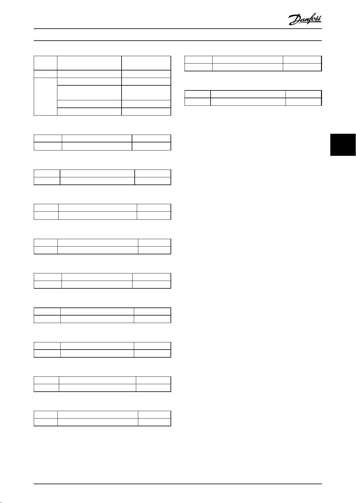
Parameter Mapping Lists
VLT® AutomationDrive FC 302 PROFIBUS Converter Operating Instructions
Parameter 620 Operation mode 14-22 Operation Mode
Options [0] Normal operation [0] Normal operation
Table 5.243 Conversion of Parameter 620
Parameter
Table 5.244 Conversion of Parameter 621
Parameter 622 Name plate: Power section Not converted
Table 5.245 Conversion of Parameter 622
Parameter
Table 5.246 Conversion of Parameter 623
VLT 5000 series FC 302 series
[1] Function with deactivated
inverter
[2] Control card test [2] Control card test
[3] Initialisation [3] Initialisation
VLT 5000 series FC 302 series
621 Name plate: VLT® type
VLT 5000 series FC 302 series
VLT 5000 series FC 302 series
623 Name plate: VLT® ordering no.
Not supported
Not converted
Not converted
Parameter 630 Name plate: Com. type Not converted
Table 5.253 Conversion of Parameter 630
Parameter 631 Name plate: Com. Type no. Not converted
Table 5.254 Conversion of Parameter 631
VLT 5000 series FC 302 series
VLT 5000 series FC 302 series
5 5
Parameter 624 Name plate: Software version no. Not converted
Table 5.247 Conversion of Parameter 624
Parameter 625 Name plate: LCP ID no. Not converted
Table 5.248 Conversion of Parameter 625
Parameter 626 Name plate: Data base ID Not converted
Table 5.249 Conversion of Parameter 626
Parameter 627 Name plate: Power ID no. Not converted
Table 5.250 Conversion of Parameter 627
Parameter 628 Name plate: Application type Not converted
Table 5.251 Conversion of Parameter 628
Parameter 629 Name plate: Application type no. Not converted
VLT 5000 series FC 302 series
VLT 5000 series FC 302 series
VLT 5000 series FC 302 series
VLT 5000 series FC 302 series
VLT 5000 series FC 302 series
VLT 5000 series FC 302 series
Table 5.252 Conversion of Parameter 629
MG34N202 - Rev. 2013-10-15 37
Page 40
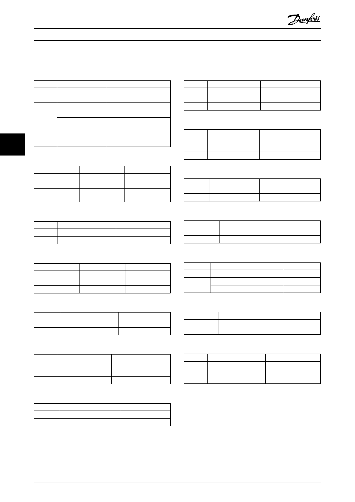
Parameter Mapping Lists
5.8
VLT® 5000 Parameter Group 7
VLT® AutomationDrive FC 302 PROFIBUS Converter Operating Instructions
Parameter 700 System control 8-02 Control Word Source
Options [0] Enable SyncPos Par. 8-02: [5] Option C0
55
Table 5.255 Conversion of Parameter 700
Parameter 701 Program
Options -1 – 127 -1 – 127
Table 5.256 Conversion of Parameter 701
Parameter 702 PID Proportional factor 32-60 Proportional factor
Options 0 – 65000 0 – 100000
Table 5.257 Conversion of Parameter 702
VLT 5000 series FC 302 series
33-82 Drive Status Monitoring
Par. 33-82: [1] On
[1] Disable SyncPos Par. 8-02: [1] FC RS-485
[2] Enable SyncPos
without VLT
monitoring
VLT 5000 series FC 302 series
number
VLT 5000 series FC 302 series
Par. 8-02: [5] Option C0
Par. 33-82: [0] Off
33-80 Activated
Program Number
Parameter 707 PID Velocity Feed-
Options 0 – 65000 0 – 100000
Table 5.262 Conversion of Parameter 707
Parameter 708 PID Acceleration
Options 0 – 65000 0 – 100000
Table 5.263 Conversion of Parameter 708
Parameter 709 PID Velocity filter 33-26 Velocity Filter
Options -500000 – 500000 -1073741824 – 107374203
Table 5.264 Conversion of Parameter 709
Parameter 710 - 779 19-10 -19-79
Options User defined User defined
Table 5.265 Conversion of Parameters 710 to 779
VLT 5000 series FC 302 series
32-65 Velocity Feed-
forward
VLT 5000 series FC 302 series
Feed-forward
VLT 5000 series FC 302 series
VLT 5000 series FC 302 series
Forward
32-66 Acceleration FeedForward
Parameter 703 PID Derivative
Options 0 – 65000 0 – 100000
Table 5.258 Conversion of Parameter 703
Parameter 704 PID Integral factor 32-62 Integral factor
Options 0 – 65000 0 – 100000
Table 5.259 Conversion of Parameter 704
Parameter 705 PID Integral
Options 0 – 1000 0 – 1000
Table 5.260 Conversion of Parameter 705
Parameter 706 PID Active bandwidth 32-64 PID Bandwidth
Options 0 – 65000 0 – 1000
Table 5.261 Conversion of Parameter 706
VLT 5000 series FC 302 series
VLT 5000 series FC 302 series
bandwidth
VLT 5000 series FC 302 series
VLT 5000 series FC 302 series
32-61 Derivative
factor
factor
32-63 Limit Value for
Integral Sum
Parameter 780 Dead time compensation Not supported
Options [0] Off
Table 5.266 Conversion of Parameter 780
Parameter 781 Program ID Not supported
Options 0 – 65000
Table 5.267 Conversion of Parameter 781
Parameter 795 - 799 User defined
Options User defined User defined
Table 5.268 Conversion of Parameters 795 to 799
VLT 5000 series FC 302 series
[1] On
VLT 5000 series FC 302 series
VLT 5000 series FC 302 series
19-95 -19-99 User
(read only)
defined (read only)
38 MG34N202 - Rev. 2013-10-15
Page 41
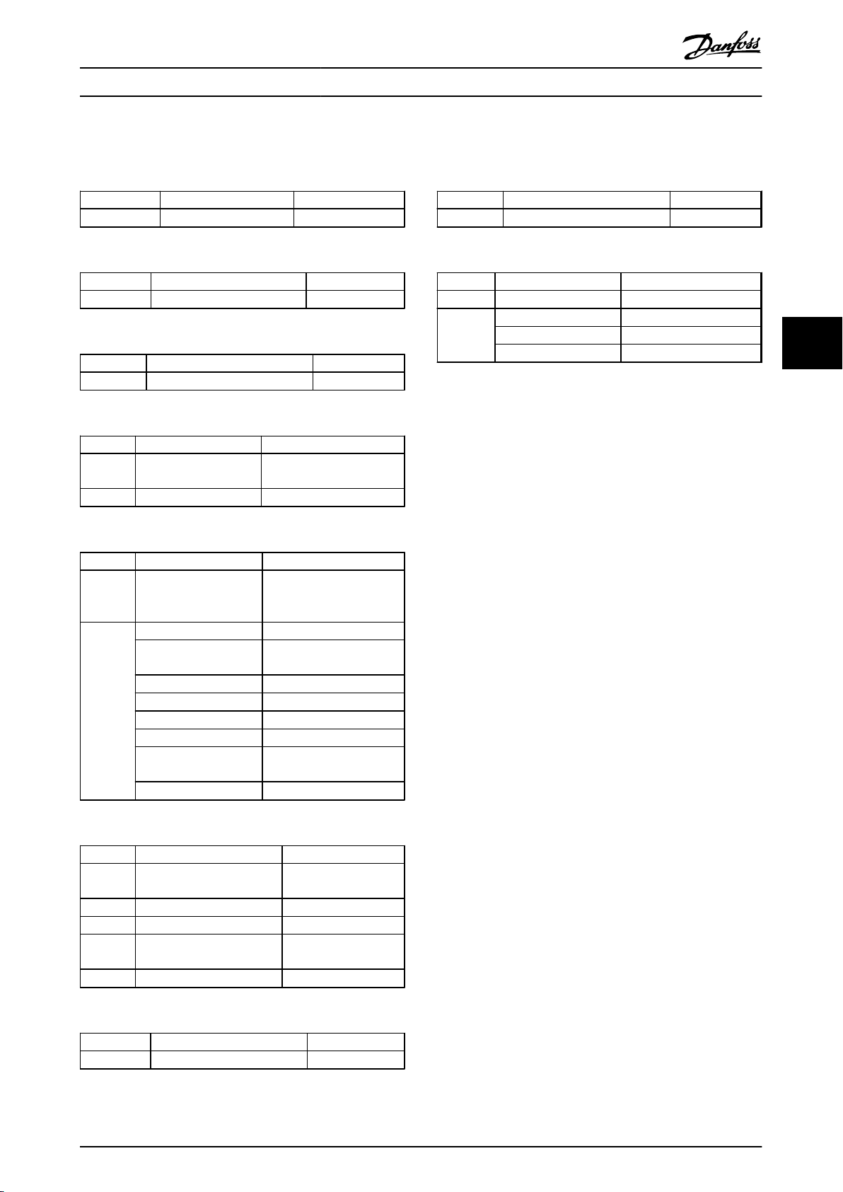
Parameter Mapping Lists
5.9
VLT® 5000 Parameter Group 8
VLT® AutomationDrive FC 302 PROFIBUS Converter Operating Instructions
Parameter 800 PROFIBUS DP Not converted
Table 5.269 Conversion of Parameter 800
Parameter 801 Baud rate selection Not converted
Table 5.270 Conversion of Parameter 801
Parameter 802 Minimum station delay Not converted
Table 5.271 Conversion of Parameter 802
Parameter 803 Time out after bus
Range 1 – 99 0.1 – 18000.0
Table 5.272 Conversion of Parameter 803
Parameter 804 Response after bus
Range [0] Off [0] Off
VLT 5000 series FC 302 series
VLT 5000 series FC 302 series
VLT 5000 series FC 302 series
VLT 5000 series FC 302 series
8-03 Control Word Timeout
error
VLT 5000 series FC 302 series
time out
[1] Freeze output
frequency
[2] Stop [2] Stop
[3] Jogging [3] Jogging
[4] Max speed [4] Max speed
[5] Stop and trip [5] Stop and trip
[6] No com. option
control
[7] Select set up 4 [10] Select set up 4
Time
8-04 Control Word Timeout
Function
8-02 Control Word Source
[1] Freeze output
frequency
Par. 802 to RS485
Parameter 808 ProfiDrives status word Not converted
Table 5.276 Conversion of Parameter 808
Parameter 849 Extended diagnose 8-07 Diagnosis Trigger
Options [0] Disable [0] Disable
Table 5.277 Conversion of Parameter 849
VLT 5000 series FC 302 series
VLT 5000 series FC 302 series
[1] Alarm [1] Trigger on alarm
[2] Alarm and warnings [2] Trigger on alarm/warn.
5 5
Table 5.273 Conversion of Parameter 804
Parameter 805 Function of control
Range [0] No function [0] None
[1] Bit 10 = 1 => CTW active [1] Profile default
[2] Bit 10 = 0 => CTW active [2] CTW Valid, active
[3] Bit 10 = 1 => Time out [1] Profile default
Table 5.274 Conversion of Parameter 805
Parameter 806 SAP selection (FMS) Not converted
Table 5.275 Conversion of Parameter 806
VLT 5000 series FC 302 series
8-14 Configurable
word bit 10
VLT 5000 series FC 302 series
Control Word CTW
low
MG34N202 - Rev. 2013-10-15 39
Page 42
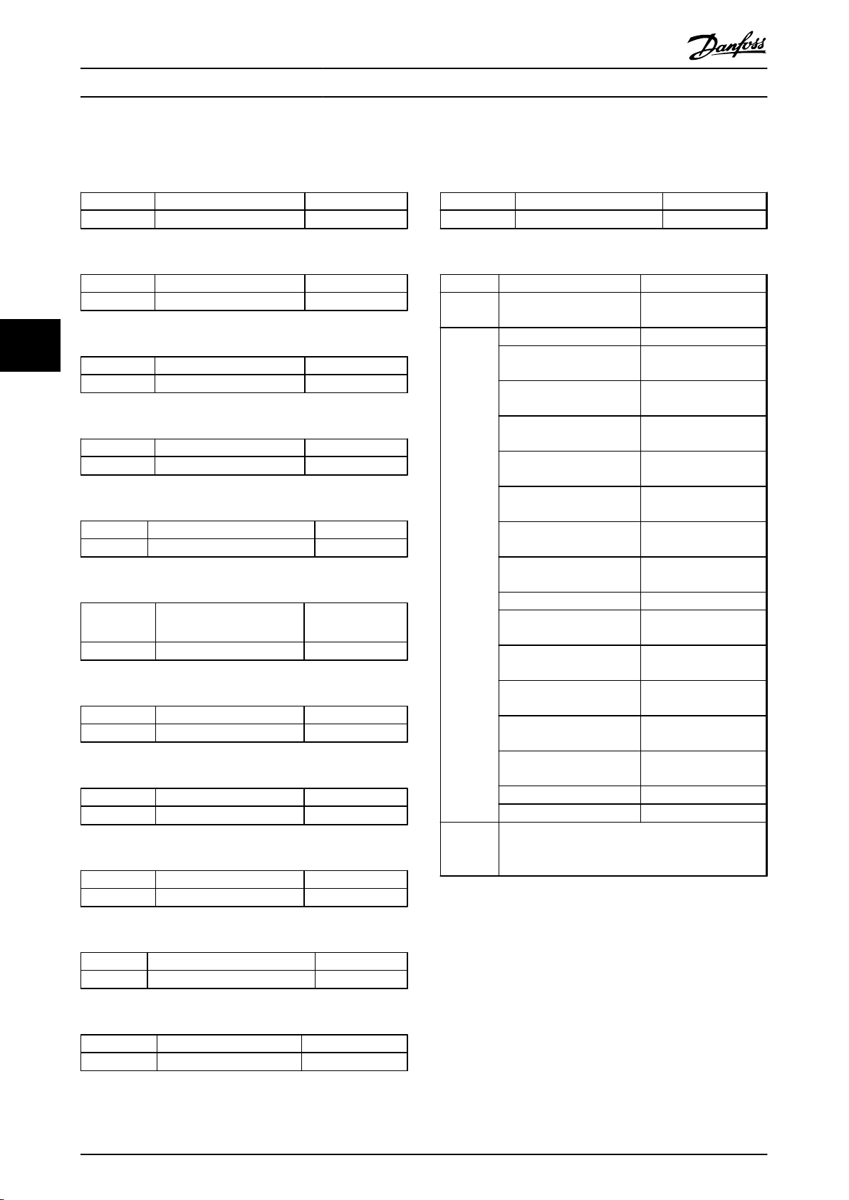
Parameter Mapping Lists
5.10
VLT® 5000 Parameter Group 9
VLT® AutomationDrive FC 302 PROFIBUS Converter Operating Instructions
Parameter 900 Write PPO type 1 Not converted
Table 5.278 Conversion of Parameter 900
Parameter 901 Write PPO type 2 Not converted
Table 5.279 Conversion of Parameter 901
VLT 5000 series FC 302 series
VLT 5000 series FC 302 series
55
Parameter 902 Write PPO type 3 Not converted
Table 5.280 Conversion of Parameter 902
Parameter 903 Write PPO type 4 Not converted
Table 5.281 Conversion of Parameter 903
Parameter 904 PPO type select for DP Not converted
Table 5.282 Conversion of Parameter 904
Parameter 907 Read PPO type 1 Not converted
Table 5.283 Conversion of Parameter 907
Parameter 908 Read PPO type 2 Not converted
Table 5.284 Conversion of Parameter 908
Parameter 909 Read PPO type 3 Not converted
Table 5.285 Conversion of Parameter 909
Parameter 910 Read PPO type 4 Not converted
VLT 5000 series FC 302 series
VLT 5000 series FC 302 series
VLT 5000 series FC 302 series
VLT 5000 series FC 302 series
VLT 5000 series FC 302 series
VLT 5000 series FC 302 series
VLT 5000 series FC 302 series
Parameter 914 Broadcast off-set Not converted
Table 5.289 Conversion of Parameter 914
Parameter 915 PCD config write 9-15 PCD Write Config-
Options [0] None [0] None
Comments
Table 5.290 Conversion of Parameter 915
VLT 5000 series FC 302 series
VLT 5000 series FC 302 series
uration
[204] Minimum Reference [302] Minimum
Reference
[205] Maximum Reference [203] Maximum
Reference
[219] Catch up/slow Down
Value
[207] Ramp 1 Ramp up
Time
[208] Ramp 1 Ramp Down
Time
[209] Ramp 2 Ramp up
Time
[210] Ramp 2 Ramp down
Time
[211] Jog Ramp Time [380] Jog Ramp Time
[212] Quick Stop Ramp
Time
[201] Motor Low Limit [Hz] [412] Motor Speed Low
[202] Motor High Limit [Hz] [414] Motor Speed High
[221] Torque Limit Motor
Mode
[222] Torque Limit
Generator Mode
[509] Bus Jog 1 Speed [890] Bus Jog 1 Speed
[510] Bus Jog 2 Speed [891] Bus Jog 2 Speed
VLT® 5000 supports more write signals. If a notsupported signal is written then the corresponding
signal is set to [0] None.
[312] Catch up/slow
Down Value
[341] Ramp 1 Ramp up
Time
[342] Ramp 1 Ramp
Down Time
[351] Ramp 2 Ramp up
Time
[352] Ramp 2 Ramp
down Time
[381] Quick Stop Ramp
Time
Limit [Hz]
Limit [Hz]
[416] Torque Limit
Motor Mode
[417] Torque Limit
Generator Mode
Table 5.286 Conversion of Parameter 910
Parameter 911 PPO type for FMS read Not converted
Table 5.287 Conversion of Parameter 911
Parameter 913 Broadcast index Not converted
Table 5.288 Conversion of Parameter 913
40 MG34N202 - Rev. 2013-10-15
VLT 5000 series FC 302 series
VLT 5000 series FC 302 series
Page 43
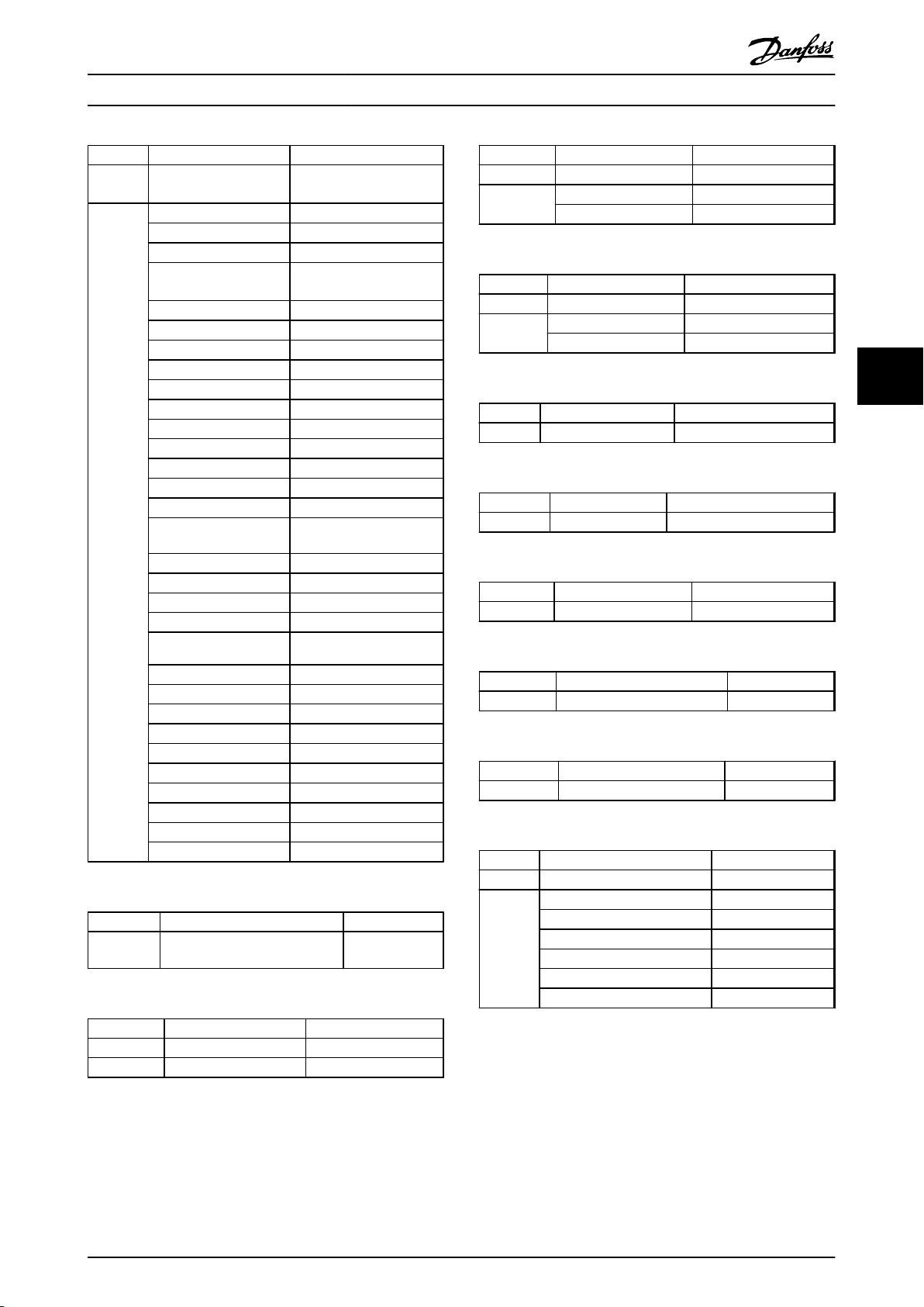
Parameter Mapping Lists
VLT® AutomationDrive FC 302 PROFIBUS Converter Operating Instructions
Parameter 916 PCD config read 9-16 PCD Read Configu-
Options [0] None [0] None
VLT 5000 series FC 302 series
ration
[538] Alarm word [1472] VLT Alarm Word
[540] Warning word [1473] VLT Warning Word
[541] Ext. status word [1474] VLT Ext. status
Word
[600] Operating hours [1500] Operating hours
[601] Running hours [1501] Running hours
[602] kWh Counter [1502] kWh Counter
[539] Control word [1600] Control word
[516] Reference [Unit] [1601] Reference [Unit]
[515] Reference % [1602] Reference %
[534] Status word [1603] Status word
[522] Power [kW] [1610] Power [kW]
[523] Power [HP] [1611] Power [HP]
[524] Motor voltage [1612] Motor voltage
[518] Motor frequency [1613] Motor frequency
[520] Motor current [1614] Motor current
[557] Motor RPM [1617] Motor speed
[526] Motor thermal [1618] Motor thermal
[521] Torque [1622] Torque %
[525] DC link voltage [1630] DC link voltage
[536] Brake energy/s [1632] Brake energy/s
Parameter 927 Parameter edit 9-27 Parameter Edit
Options [0] Disable [0] Disable
Table 5.294 Conversion of Parameter 927
Parameter 928 Control authority 9-28 Process Control
Options [0] Disable [0] Disable
Table 5.295 Conversion of Parameter 928
Parameter 953 Warning parameter 9-53 Profibus Warning Word
Table 5.296 Conversion of Parameter 953
Parameter 964 Identification 9-64 Device Identification
Table 5.297 Conversion of Parameter 964
Parameter 965 Profile Number 9-65 Profile Number
Table 5.298 Conversion of Parameter 965
VLT 5000 series FC 302 series
[1] Enable [1] Enable
VLT 5000 series FC 302 series
[1] Enable [1] Enable cyclic master
VLT 5000 series FC 302 series
VLT 5000 series FC 302 series
VLT 5000 series FC 302 series
5 5
[535] Brake energy/2 min [1633] Brake energy/2 min
[537] Heat sink temp. [1634] Heat sink temp.
[527] Inverter Thermal [1635] Inverter Thermal
[533] External reference [1650] External reference
[532] Pulse reference [1651] Pulse reference
[517] Feedback [Unit] [1652] Feedback [Unit]
[528] Digital input [1660] Digital input
[529] Analog input 53 [1662] Analog input 53
[530] Analog input 54 [1664] Analog input 54
[531] Analog input 60 [1664] Analog input 54
Table 5.291 Conversion of Parameter 916
Parameter 917 Spontaneous messages Not converted
Table 5.292 Conversion of Parameter 917
Parameter 918 Station address 9-18 Node Address
Range 0 - 125 0 - 125
Table 5.293 Conversion of Parameter 918
VLT 5000 series FC 302 series
VLT 5000 series FC 302 series
Parameter 967 Control word (FMS) Not converted
Table 5.299 Conversion of Parameter 967
Parameter 968 Status word (FMS) Not converted
Table 5.300 Conversion of Parameter 968
Parameter 970 Parameter set-up selection 9-70 Edit Set-up
Options [0] Factory setting [0] Factory setting
Table 5.301 Conversion of Parameter 970
VLT 5000 series FC 302 series
VLT 5000 series FC 302 series
VLT 5000 series FC 302 series
[1] Parameter setup 1 [1] Parameter setup 1
[2] Parameter setup 2 [2] Parameter setup 2
[3] Parameter setup 3 [3] Parameter setup 3
[4] Parameter setup 4 [4] Parameter setup 4
[5] Active setup [9] Active setup
MG34N202 - Rev. 2013-10-15 41
Page 44

Parameter Mapping Lists
VLT® AutomationDrive FC 302 PROFIBUS Converter Operating Instructions
Parameter 971 Save data values 9-71 Profibus Save Data Values
Options Unsigned 8 (5) Unsigned 8 (5)
Table 5.302 Conversion of Parameter 971
Parameter 980, 981, 982, 990 Modified
55
Table 5.303 Conversion of Parameter 980-990
VLT 5000 series FC 302 series
[0] Not active [0] Off
[1] Save active setup [1] Store all setups
[2] Save edit setup [1] Store all setups
[3] Save all setups [1] Store all setups
VLT 5000 series FC 302 series
Not converted
parameters
42 MG34N202 - Rev. 2013-10-15
Page 45

Troubleshooting
VLT® AutomationDrive FC 302 PROFIBUS Converter Operating Instructions
6 Troubleshooting
6.1 Step-by-step Troubleshooting
After copying the station address from the VLT® 5000 to
the VLT® AutomationDrive FC 302, power must be cycled
to the FC 302. The master/PLC should now recognise FC
302 as a VLT® 5000. The NS LED on the MCA 114 option
should now be solid green indicating that communication
between master and slave is established.
If the NS LED flashes, the master/PLC has not recognized
the FC 302:
Check if station address is the same in the FC 302
•
as the replaced VLT® 5000.
Check 9-63 Actual Baud Rate. If the frequency
•
converter has a connection to the master, this
parameter displays the detected baudrate. If no
master has been detected, the parameter
displays: “No baud rate found”.
Check 9-53 Profibus Warning Word.
•
Bit
Warn. Word
[Hex]
0 0001 Connection with DP-master is not OK
1 0002 Unused
2 0004
3 0008 Clear data command received
4 0010 Actual value is not updated
5 0020 Baudrate search
6 0040 PROFIBUS ASIC is not transmitting
7 0080 Initialising of PROFIBUS is not ok
8 0100 Drive is tripped
9 0200 Internal CAN error
10 0400 Wrong configuration data from PLC
11 0800 Wrong ID sent by PLC
12 1000 Internal error occurred
13 2000 Not configured
14 4000 Timeout active
15 8000 Warning 34 active
FDL (Field-bus Data link Layer) is not
OK
Description
6 6
Table 6.1 Warning Word
Check 1.3 Constraints for more information on
•
limitations.
MG34N202 - Rev. 2013-10-15 43
Page 46

Index
VLT® AutomationDrive FC 302 PROFIBUS Converter Operating Instructions
Index
A
Abbreviations.......................................................................................... 5
T
Terminal..................................................................................................... 4
Troubleshooting.................................................................................. 43
B
Brake chopper......................................................................................... 3
C
Commissioning.................................................................................... 10
Configuration.......................................................................................... 3
Constrains................................................................................................. 3
D
DIP switches............................................................................................. 9
E
EMC precautions.................................................................................... 8
H
Hardware................................................................................................... 4
High voltage............................................................................................ 6
I
Installation................................................................................................ 7
W
Warning word....................................................................................... 43
L
LEDs........................................................................................................... 10
Linked Set-ups........................................................................................ 5
Literature................................................................................................... 3
M
MCA 114.................................................................................................. 43
Mechanical Installation....................................................................... 8
N
Node address........................................................................................... 9
O
Overview (technical)............................................................................ 3
P
Parameter (mapping list)................................................................. 12
Performance............................................................................................ 5
Power size................................................................................................. 3
44 MG34N202 - Rev. 2013-10-15
Page 47

Index
VLT® AutomationDrive FC 302 PROFIBUS Converter Operating Instructions
MG34N202 - Rev. 2013-10-15 45
Page 48
www.danfoss.com/drives
130R0371 MG34N202 Rev. 2013-10-15
*MG34N202*
 Loading...