

Page 1
MAKING MODERN LIVING POSSIBLE
Installation Guide
VLT® CANopen MCA 105
VLT® AutomationDrive FC 301/302
vlt-drives.danfoss.com
Page 2

Page 3

Contents Installation Guide
Contents
1 Introduction
1.1 Purpose of the Manual
1.2 Additional Resources
1.3 Product Overview
1.4 Approvals and Certications
1.5 Disposal
1.6 Symbols, Abbreviations, and Conventions
2 Safety
2.1 Safety Symbols
2.2 Qualied Personnel
2.3 Safety Precautions
3 Installation
3.1 Safety Instructions
3.2 EMC-compliant Installation
3.3 Grounding
3.4 Cable Routing
2
2
2
2
2
3
3
4
4
4
4
6
6
6
6
6
3.5 Mounting
3.6 Setting Address Switches
3.7 Electrical Installation
3.8 Reassembling Cover
3.9 Applying Power
3.10 Checking Network Cabling
4 Troubleshooting
4.1 Warnings and Alarms
4.2 Troubleshooting
4.2.1 LED Status 11
4.2.2 No Communication with the Frequency Converter 11
Index
7
8
8
10
10
10
11
11
11
12
MG33J402 Danfoss A/S © 05/2015 All rights reserved. 1
Page 4

Introduction
VLT® CANopen MCA 105
11
1 Introduction
1.1 Purpose of the Manual
This installation guide provides information for quick instal-
lation of a VLT® CANopen MCA 105 interface in the VLT
frequency converter.
The installation guide is intended for use by qualied
personnel. Users are assumed to be familiar with the VLT
frequency converter, with CANopen technology, and with
the PC or PLC that is used as a master in the system.
Read the instructions before installation and ensure that
instructions for safe installation are observed.
VLT® is a registered trademark.
1.2 Additional Resources
Resources available for the frequency converters and
optional equipment:
The VLT® AutomationDrive FC 301/FC 302
•
Operating Instructions provide the necessary
information for getting the frequency converter
up and running.
®
®
Product Overview
1.3
1.3.1 Intended Use
This installation guide relates to the CANopen interface.
Ordering numbers:
130B1103 (uncoated)
•
130B1205 (coated)
•
CANopen is a low-level network that standardises only
communications between industrial devices (sensors, limit
switches, motor controls) and high-level devices
(controllers). Congure CANopen systems to operate in a
master-slave or in a distributed control architecture using
peer-to-peer communication.
The CANopen interface is designed to communicate with
any master abiding by the CANopen standard.
VLT® CANopen MCA 105 is intended for use with VLT
AutomationDrive FC 301/FC 302.
®
The VLT® AutomationDrive FC 301/FC 302 Design
•
Guide provides detailed information about
capabilities and functionality to design motor
control systems.
The VLT® AutomationDrive FC 301/FC 302
•
Programming Guide provides greater detail on
working with parameters and many application
examples.
The VLT® CANopen MCA 105 Installation Guide
•
provides information about installing the
CANopen and troubleshooting.
The VLT® CANopen MCA 105 Programming Guide
•
provides information about conguring the
system, controlling the frequency converter,
parameter access, programming, troubleshooting,
as well as some typical application examples.
Supplementary publications and manuals are available
from Danfoss. See vlt-drives.danfoss.com/Support/Technical-
Documentation/ for listings.
1.3.2 Items Supplied
When the eldbus option is not factory mounted, the
following items are supplied:
Fieldbus option and connector.
•
LCP cradle.
•
Front covers (in various sizes).
•
Stickers.
•
Accessories bag (including EMC bracket).
•
Installation guide.
•
Approvals and Certications
1.4
More approvals and certications are available. For more
information, contact a Danfoss local partner.
2 Danfoss A/S © 05/2015 All rights reserved. MG33J402
Page 5
Introduction Installation Guide
1.5 Disposal
Do not dispose of equipment containing
electrical components together with
domestic waste.
Collect it separately in accordance with
local and currently valid legislation.
1.6 Symbols, Abbreviations, and
Conventions
Abbreviation Denition
CAN Controller area network
CiA CAN in automation
COB Communication object
COB-ID Communication object identier
CTW Control word
EDS Electronic data sheet
EMC Electromagnetic compatibility
EMCY Emergency message
I/O Input/output
LCP Local control panel
LED Light emitting diode
LSB Least signicant bit
MAV Main actual value (actual output)
MRV Main reference value
MSB Most signicant bit
NMT Network management
N/A Not applicable
OD Object directory
PCD Process data
PDO Process data object
PLC Programmable logic controller
PNU Parameter number
RPDO Receive process data object
RPM Revolutions per minute; unit for the speed of a
revolving motor
RTR Remote transmission request frame
RX Receive data
STW Status word
SDO Service data object
SYNC Object for synchronisation of process data
TPDO Transmit process data object
TX Transmit data
Conventions
Numbered lists indicate procedures.
Bullet lists indicate other information and descriptions of
illustrations.
Italicised text indicates:
Cross-reference.
•
Link.
•
Parameter name.
•
Footnote.
•
Parameter group.
•
Parameter option.
•
Alarms/warnings.
•
1 1
Table 1.1 Symbols and Abbreviations
MG33J402 Danfoss A/S © 05/2015 All rights reserved. 3
Page 6
Safety
VLT® CANopen MCA 105
2 Safety
22
2.1 Safety Symbols
WARNING
The following symbols are used in this manual:
WARNING
Indicates a potentially hazardous situation that could
result in death or serious injury.
CAUTION
Indicates a potentially hazardous situation that could
result in minor or moderate injury. It can also be used to
alert against unsafe practices.
NOTICE
Indicates important information, including situations that
can result in damage to equipment or property.
2.2 Qualied Personnel
Correct and reliable transport, storage, installation,
operation, and maintenance are required for the troublefree and safe operation of the frequency converter. Only
qualied personnel are allowed to install and operate this
equipment.
Qualied personnel are dened as trained sta, who are
authorised to install, commission, and maintain equipment,
systems, and circuits in accordance with pertinent laws and
regulations. Additionally, the qualied personnel must be
familiar with the instructions and safety measures
described in these operating instructions.
Safety Precautions
2.3
WARNING
HIGH VOLTAGE
Frequency converters contain high voltage when
connected to AC mains input, DC supply, or load sharing.
Failure to perform installation, start-up, and maintenance
by qualied personnel can result in death or serious
injury.
Only qualied personnel must perform instal-
•
lation, start-up, and maintenance.
UNINTENDED START
When the frequency converter is connected to AC mains,
DC supply, or load sharing, the motor may start at any
time. Unintended start during programming, service, or
repair work can result in death, serious injury, or
property damage. The motor can start with an external
switch, a eldbus command, an input reference signal
from the LCP or LOP, via remote operation using MCT 10
Set-up Software, or after a cleared fault condition.
To prevent unintended motor start:
Disconnect the frequency converter from the
•
mains.
Press [O/Reset] on the LCP before
•
programming parameters.
Completely wire and assemble the frequency
•
converter, motor, and any driven equipment
before connecting the frequency converter to
AC mains, DC supply, or load sharing.
WARNING
DISCHARGE TIME
The frequency converter contains DC-link capacitors that
can remain charged even when the frequency converter
is not powered. Failure to wait the specied time after
power has been removed before performing service or
repair work, can result in death or serious injury.
Stop the motor.
•
Disconnect the AC mains and remote DC-link
•
supplies, including battery back-ups, UPS, and
DC-link connections to other frequency
converters.
Disconnect or lock the PM motor.
•
Wait for the capacitors to discharge fully before
•
performing any service or repair work. The
duration of waiting time is specied in the
relevant frequency converter operating
instructions, Chapter 2 Safety.
WARNING
LEAKAGE CURRENT HAZARD
Leakage currents exceed 3.5 mA. Failure to ground the
frequency converter properly can result in death or
serious injury.
Ensure the correct grounding of the equipment
•
by a certied electrical installer.
4 Danfoss A/S © 05/2015 All rights reserved. MG33J402
Page 7
Safety Installation Guide
WARNING
EQUIPMENT HAZARD
Contact with rotating shafts and electrical equipment
can result in death or serious injury.
Ensure that only trained and qualied personnel
•
perform installation, start-up, and maintenance.
Ensure that electrical work conforms to national
•
and local electrical codes.
Follow the procedures in this manual.
•
CAUTION
INTERNAL FAILURE HAZARD
An internal failure in the frequency converter can result
in serious injury, when the frequency converter is not
properly closed.
Ensure that all safety covers are in place and
•
securely fastened before applying power.
2 2
MG33J402 Danfoss A/S © 05/2015 All rights reserved. 5
Page 8
130BD866.10
≥ 200mm
2
1
Installation
3 Installation
VLT® CANopen MCA 105
3.1 Safety Instructions
33
See chapter 2 Safety for general safety instructions.
3.2 EMC-compliant Installation
To obtain an EMC-compliant installation, follow the
instructions provided in the relevant frequency converter
operating instructions and design guide. Refer to the
eldbus master manual from the PLC supplier for further
installation guidelines.
3.3 Grounding
Ensure that all stations connected to the eldbus
•
network are connected to the same ground
potential. When there are long distances between
the stations in a eldbus network, connect the
individual station to the same ground potential.
Install equalising cables between the system
components.
Establish a grounding connection with low HF
•
impedance, for example by mounting the
frequency converter on a conductive back plate.
Keep the ground wire connections as short as
•
possible.
Establish electrical contact between the cable
•
screen and the frequency converter enclosure by
using metal cable glands or by using the clamps
provided on the equipment.
Use high-strand wire to reduce electrical
•
interference.
Cable Routing
3.4
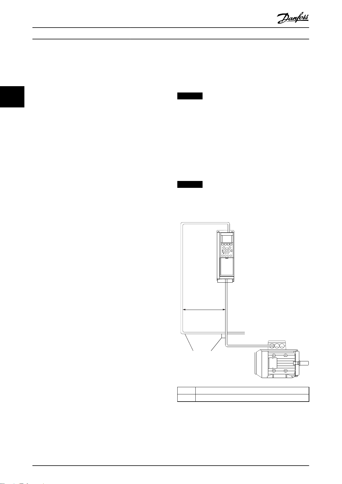
NOTICE
EMC INTERFERENCE
Use screened cables for motor and control wiring, and
separate cables for eldbus communication, motor
wiring, and brake resistor. Failure to isolate eldbus
communication from motor and brake resistor cables can
result in unintended behaviour or reduced performance.
Minimum 200 mm (7.9 in) clearance between power,
motor, and control cables is required. For power sizes
above 315 kW, it is recommended to increase the
minimum distance to 500 mm (20 in).
NOTICE
When the eldbus cable crosses a motor cable or a brake
resistor cable, ensure that the cables cross at an angle of
90°.
1 Fieldbus cable
2 90° crossing
6 Danfoss A/S © 05/2015 All rights reserved. MG33J402
Illustration 3.1 Cable Routing
Page 9

130BD876.10
1
2
4
3
130BD862.10
130BD863.10
Installation Installation Guide
3.5 Mounting
1. Check whether the eldbus option is already
mounted in the frequency converter. If already
mounted, go to step 6. If not mounted, go to
step 2.
2. Remove the LCP or blind cover from the
frequency converter.
3. Use a screwdriver to remove the front cover and
the LCP cradle.
4. Mount the eldbus option. Mount the option
with the connector facing up for top cable entry
(see Illustration 3.3), or with the connector facing
down for bottom cable entry (see Illustration 3.4).
If an MCB option is installed, only top cable entry
is possible.
5. Remove the knock-out plate from the new LCP
cradle.
6. Mount the new LCP cradle.
3 3
1 LCP
2 LCP cradle
3 Fieldbus option
4 Connector
Illustration 3.2 Exploded View
Illustration 3.3 Top Cable Entry: Option Mounted with
Connector Facing Up
MG33J402 Danfoss A/S © 05/2015 All rights reserved. 7
Illustration 3.4 Bottom Cable Entry: Option Mounted with
Connector Facing Down
Page 10

130BD877.10
1
2
Installation
VLT® CANopen MCA 105
3.6 Setting Address Switches
NOTICE
Switch o the power supply before changing the address
switches. The address change comes into eect at the
33
next power-up.
The address switches enable setting of baudrate and node
ID:
Switches 8 and 7 arefor setting the baudrate for
•
either: 125, 250, or 500 Kbps.
Switches 6–1 are for setting the node address in
•
the range 1–62.
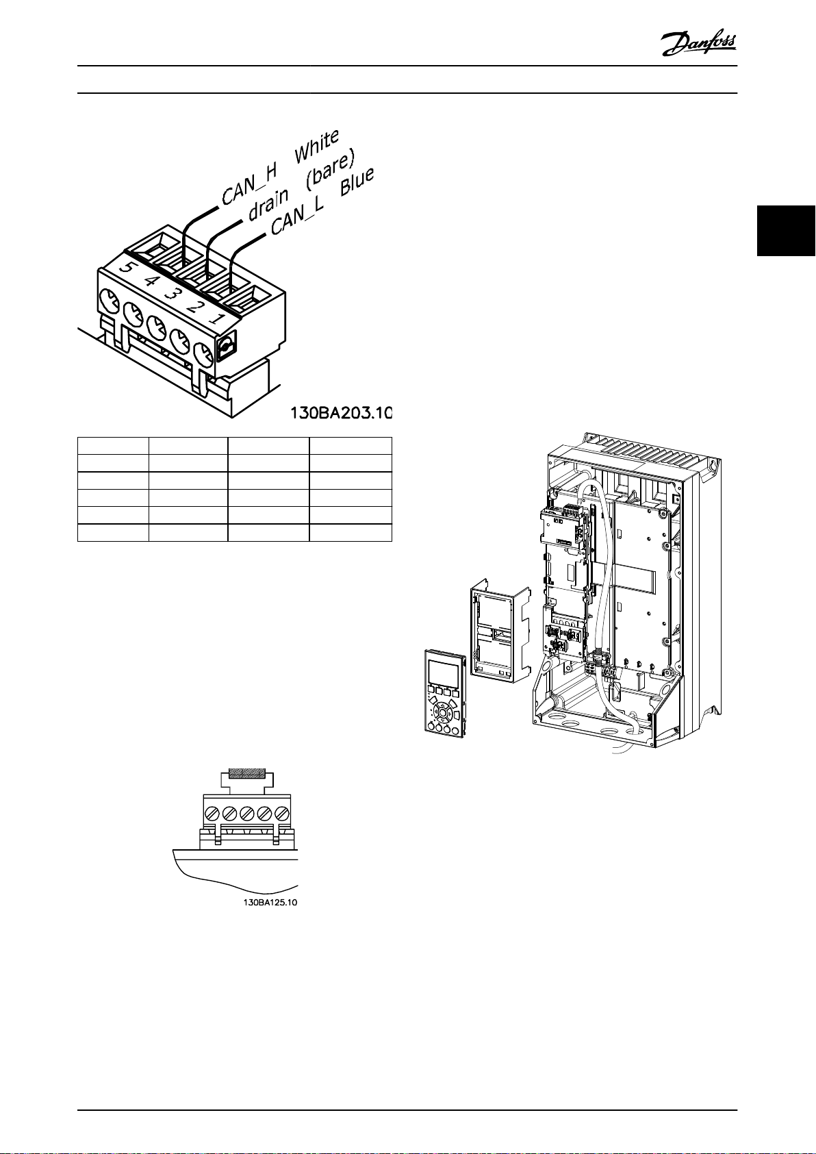
3.7.2 Wiring Procedures
Wiring procedure for enclosure sizes A1–A3
1. Mount the eldbus connector on the eldbus
option (CAN_L, Drain, CAN_H). For top cable
entry, mount the supplied EMC bracket on top of
the frequency converter with 2 screws.
2. Prepare the eldbus cable by stripping a section
of the cable insulation, so that the cable screen
contacts the EMC bracket. Keep the unshielded
wire as short as possible. For cable specications,
refer to chapter 3.7.1 Cable Specications.
3. Connect the eldbus cable wires to the terminals
according to the colour code of the wires, see
Switch Baudrate
8 7
On On Parameter 10-01 Bau
d Rate Select
On O 500 kbps
On On 250 kbps
On O 125 kbps
Table 3.1 Switches 8 and 7
Illustration 3.6.
4. To establish mechanical xation and electrical
contact between cable screen and ground,
position the stripped cable between the spring
loaded metal clamps.
Switch Node ID
6 5 4 3 2 1
On On On On On On Parameter
10-02 MAC
ID
On On On On On O 62
O O O O O On 1
Table 3.2 Switches 6–1
When both switch 8 and 7are set to ON, select baudrates
via parameter 10-01 Baud Rate Select: 10, 20, 50, 100, 125,
250, or 500 kbps.
When switches 6–1 are set to ON, select node ID via
parameter 10-02 MAC ID in the range: 1–127
Electrical Installation
3.7
3.7.1 Cable Specications
Baudrate
[kbps]
500 100 <60 0.34–0.6
250 250
125 500
50 1000
10 5000
Maximum
cable
length [m]
Resistance
[mΩ/m]
<40 0.5–0.6
<26 0.75–0.820 2500
Cable cross-
section
[mm2]
Termination
resistor [Ω]
120
1 Cable screen
2 EMC bracket (used for top cable entry only)
Illustration 3.5 Wiring for Enclosure Sizes A1–A3
Table 3.3 Cable Specications
8 Danfoss A/S © 05/2015 All rights reserved. MG33J402
Page 11
130BD864.10
Installation Installation Guide
Pin no. Terminal Colour Name
1 – – Not used
2 CAN_L Blue CAN LOW
3 Drain (bare) Screen
4 CAN_H White CAN HIGH
5 – – Not used
Wiring procedure for enclosure sizes A4–A5, B1–B4, and
C1–C4
1. Push the cable through cable glands.
2. Mount the eldbus connector on the eldbus
option ( CAN_L, Drain, CAN_H).
3. Prepare the eldbus cable by stripping a section
of the cable insulation. Keep the unshielded wire
as short as possible. For cable specications, refer
to chapter 3.7.1 Cable Specications.
4. Connect the eldbus cable wires to the terminals
according to the colour code of the wires, see
Illustration 3.6.
5. Fix the cable screen to the metal base plate using
cable clamp or cable tie, see Illustration 3.8.
6. Tighten cable glands securely.
3 3
Illustration 3.6 Fieldbus Cable Terminal Connections
CANopen termination
Install the termination resistors at each end of the bus line.
Mount the resistor between terminal 2 (CAN_L) and
terminal 4 (CAN_H).
The resistors have the following specication:
121 Ω
•
1% Metal
•
1/4 W
•
Illustration 3.7 Termination Resistor Mounted
lm
Illustration 3.8 Wiring for Enclosure Sizes A4–A5, B1–B4, and
C1–C4
MG33J402 Danfoss A/S © 05/2015 All rights reserved. 9
Page 12

130BC527.10
Installation
VLT® CANopen MCA 105
Wiring procedure for enclosure sizes D, E, and F
1. Mount the eldbus connector on the eldbus
option (CAN_L, Drain, CAN_H).
2. Prepare the eldbus cable by stripping a section
of the cable insulation. Keep unshielded wire as
33
short as possible. For cable specications, refer to
chapter 3.7.1 Cable Specications.
3. Connect the eldbus cable wires to the terminals
according to the colour code of the wires, see
Illustration 3.6.
4. Fix the cable screen to the metal base plate using
cable clamp or cable tie, see Illustration 3.9.
5. Tie down the cable and route it with other
control wires inside the unit, see Illustration 3.9.
Reassembling Cover
3.8
1. Mount the new front cover and the LCP.
2. Attach the sticker with the correct product name
to the front cover.
3.9 Applying Power
Follow the instructions in the frequency converter
operating instructions to commission the frequency
converter. The frequency converter automatically detects
the CANopen interface. A new parameter group (Group 10)
appears.
3.10 Checking Network Cabling
1. If the address has not been set via the address
switches, go to parameter 10-02 MAC ID to set the
address.
2. Connect to a running CANopen master.
3. Check that network cabling is correct or not.
Illustration 3.9 Wiring for Enclosure Sizes D, E, and F
10 Danfoss A/S © 05/2015 All rights reserved. MG33J402
Page 13

Troubleshooting Installation Guide
4 Troubleshooting
4.1 Warnings and Alarms
NOTICE
Refer to the relevant operating instructions for an
overview of warning and alarm types and for the full list
of warnings and alarms.
Alarm word, warning word, and CANopen warning word
are shown on the frequency converter display in hex
format. When there is more than 1 warning or alarm, the
sum of all warnings or alarms is shown. Alarm word,
warning word, and CANopen warning word can also be
displayed using the serial bus in:
Parameter 16-90 Alarm Word.
•
Parameter 16-91 Alarm Word 2.
•
Parameter 16-92 Warning Word.
•
Parameter 16-93 Warning Word 2.
•
4.2 Troubleshooting
4.2.1 LED Status
The 2 bi-colour LEDs on the CANopen card indicate the
status of CANopen communication:
The lower LED (NS) indicates the net status.
•
The upper LED (MS) indicates the module status.
•
Illustration 4.1 LED Panel VLT® CANopen MCA 105
State Red LED Description
No error O No error.
Warning limit
reached
Error control
event
Sync error Triple ash Sync message has not been
Bus o On Device in bus o-state.
Table 4.1 LED: Module Status (MS)
State Red LED Description
Stopped Single ash Device in stopped state.
Pre-operational Triple ash Device in pre-operational state.
Operational On Device in operational state.
Table 4.2 LED: Network Status (NS)
Single ash CAN error counter has reached/
exceeded warning level.
Double ash Node guard event has occurred.
received within the congured
timeout (object 0x1006).
4.2.2 No Communication with the
Frequency Converter
When there is no communication with the frequency
converter, proceed with the following checks:
1. Check that cabling is correct.
Check that the cables are connected to the
correct terminals as shown in Illustration 3.6.
2. Check that the bus connection is terminated at
both ends.
If not, terminate the bus connection with
termination resistors at the initial and
3. Check that each node connected to the CANopen
network has a unique node ID (address). If 2
devices have the same node ID, it leads to
malfunction in the network.
4. Communication drops out after some time. Check
the installation for correct routing of the
CANopen cables. Check if the screen of the motor
cable is mounted correctly.
5. Communication is unstable. Check
parameter 10-05 Readout Transmit Error Counter
and parameter 10-06 Readout Receive Error
Counter. These 2 parameters have to be close to 0
most of the time. If they show higher values,
check the CANopen cable for interference, wrong
termination, and so on.
nal nodes.
4 4
MG33J402 Danfoss A/S © 05/2015 All rights reserved. 11
Page 14

Index
VLT® CANopen MCA 105
Index
A
Abbreviations........................................................................................... 3
Additional resources.............................................................................. 2
Address switch.................................................................................. 8, 10
Alarm......................................................................................................... 11
Alarm word............................................................................................. 11
Applying power.................................................................................... 10
Approvals................................................................................................... 2
C
Cable specications............................................................................... 8
Cable terminal connections................................................................ 9
CANopen termination........................................................................... 9
Certications............................................................................................. 2
Conventions.............................................................................................. 3
N
Network cabling.................................................................................... 10
P
Power, applying..................................................................................... 10
Q
Qualied personnel................................................................................ 4
S
Safety........................................................................................................... 5
Screened cable......................................................................................... 6
Symbols...................................................................................................... 3
U
Unintended start..................................................................................... 4
D
Discharge time......................................................................................... 4
E
Electrical interference............................................................................ 6
EMC interference..................................................................................... 6
EMC-compliant installation................................................................. 6
Exploded view.......................................................................................... 7
G
Grounding................................................................................................. 6
H
High voltage............................................................................................. 4
I
Intended use............................................................................................. 2
Items supplied.......................................................................................... 2
L
Leakage current....................................................................................... 4
LED panel................................................................................................. 11
LED status................................................................................................ 11
Load sharing............................................................................................. 4
W
Warning.................................................................................................... 11
Warning word........................................................................................ 11
Wiring procedure.................................................................................... 8
M
Motor wiring............................................................................................. 6
Mounting................................................................................................... 7
12 Danfoss A/S © 05/2015 All rights reserved. MG33J402
Page 15

Index Installation Guide
MG33J402 Danfoss A/S © 05/2015 All rights reserved. 13
Page 16

Danfoss can accept no responsibility for possible errors in catalogues, brochures and other printed material. Danfoss reserves the right to alter its products without notice. This also applies to
products already on order provided that such alterations can be made without subsequential changes being necessary in specications already agreed. All trademarks in this material are property
of the respective companies. Danfoss and the Danfoss logotype are trademarks of Danfoss A/S. All rights reserved.
Danfoss A/S
Ulsnaes 1
DK-6300 Graasten
vlt-drives.danfoss.com
130R0067 MG33J402 05/2015
*MG33J402*
 Loading...