

Page 1
MAKING MODERN LIVING POSSIBLE
Programming Guide
VLT® CANopen MCA 105
VLT® AutomationDrive FC 301/302
vlt-drives.danfoss.com
Page 2

Page 3

Contents Programming Guide
Contents
1 Introduction
1.1 Purpose of the Manual
1.2 Additional Resources
1.3 Document and Software Version
1.4 Product Overview
1.5 Approvals and Certications
1.6 Symbols, Abbreviations, and Conventions
2 Safety
2.1 Safety Symbols
2.2 Qualied Personnel
2.3 Safety Precautions
3 Conguration
3.1 Congure the CANopen Network
3.2 Congure the Master
3.3 Congure the Frequency Converter
3
3
3
3
3
4
4
5
5
5
5
7
7
10
13
4 Control
4.1 PDO Communication
4.1.1 PDO Conguration 15
4.1.2 PDO Mapping Syntax 17
4.1.3 PDO Transmission Modes 17
4.1.4 PDO Triggering Modes 17
4.1.5 Inhibit Time 17
4.1.6 Event Timer 17
4.2 Control Prole
4.3 DSP 402 Control Prole
4.4 Danfoss FC control prole
4.4.1 Control Word according to FC Prole
(parameter 8-10 = FC prole) 22
4.4.2 Status Word according to FC Prole
(parameter 8-10 = FC prole) 23
4.5 Reference Handling
5 Parameter Access
14
14
18
20
22
25
26
5.1 Danfoss Specic Objects (2000h-5FFFh)
6 Parameters
6.1 Parameter List
7 Object Directory
MG92G102 Danfoss A/S © 06/2015 All rights reserved. 1
26
27
35
37
Page 4

Contents
VLT® CANopen MCA 105
7.1 Communication Prole Area (1000h-1FFFh)
7.1.1 Communication Object Overview 37
7.1.2 1000h Device Type 38
7.1.3 1001h Error Register 38
7.1.4 1002h Manufacturer Status Register 38
7.1.5 1003h Predened Error Field 38
7.1.6 1005h COB-ID Sync Message Object 38
7.1.7 1008h Manufacturer Device Name 38
7.1.8 1009h Manufacturer Hardware Version 38
7.1.9 100Ah Manufacturer Software Version 39
7.1.10 100Ch Guard Time 39
7.1.11 100Dh Life Time Factor 39
7.1.12 1010h Store Parameters 39
7.1.13 1011h Restore Default Parameters 39
7.1.14 1014h COB ID Emergency Object 39
7.1.15 1017h Producer Heartbeat Time 39
7.1.16 1018h Identity Object 39
37
8 Troubleshooting
8.1 Warnings and Alarms
8.2 Troubleshooting
Index
40
40
43
46
2 Danfoss A/S © 06/2015 All rights reserved. MG92G102
Page 5

Introduction Programming Guide
1 Introduction
1.1 Purpose of the Manual
The VLT® CANopen MCA 105 Programming Guide provides
information about conguring the system, controlling the
frequency converter, parameter access, programming, as
well as troubleshooting.
The programming guide is intended for use by qualied
personnel who are familiar with the VLT® frequency
converter, with CANopen technology, and with the PC or
PLC that is used as a master in the system.
Read the instructions before programming and follow the
procedures in this manual.
VLT® is a registered trademark.
1.2 Additional Resources
Resources available for the frequency converters and
optional equipment:
The VLT® AutomationDrive FC 301/FC 302
•
Operating Instructions provide the necessary
information for getting the frequency converter
up and running.
The VLT® AutomationDrive FC 301/FC 302 Design
•
Guide provides detailed information about
capabilities and functionality to design motor
control systems.
The VLT® AutomationDrive FC 301/FC 302
•
Programming Guide provides greater detail on
working with parameters and many application
examples.
The VLT® CANopen MCA 105 Installation Guide
•
provides information about installing the
CANopen and troubleshooting.
The VLT® CANopen MCA 105 Programming Guide
•
provides information about conguring the
system, controlling the frequency converter,
parameter access, programming, troubleshooting,
as well as some typical application examples.
Supplementary publications and manuals are available
from Danfoss. See vlt-drives.danfoss.com/Support/Technical-
Documentation/ for listings.
Document and Software Version
1.3
This manual is regularly reviewed and updated. All
suggestions for improvement are welcome. Table 1.1 shows
the document version and the corresponding software
version.
Edition Remarks Software version
MG92G1xx – –
Table 1.1 Document and Software Version
1.4 Product Overview
This programming guide relates to the CANopen interface.
Ordering number:
130B1103 (uncoated)
•
130B1205 (coated)
•
CANopen is a low-level network that standardises
communications between industrial devices (sensors, limit
switches, motor controls) and high-level devices
(controllers). CANopen follows the open systems interconnection (OSI) model and is based on CAN technology for
media access control and physical signalling.
Congure CANopen systems to operate in a master-slave
or a distributed control architecture using peer-to-peer
communication. Up to 127 nodes in a multi-drop network
topology are supported. By using the same cable for
communication, the bus can power the communication
options directly. Nodes can be removed or inserted
without powering down the network.
Each node on the network has its own unique communication object identier (COB-ID) to distinguish it on the
network. The access control is based on the CSMA/CA
(carrier sense multiple access/collision avoidance) principle,
meaning that all nodes may have access to the network at
the same time. When 2 nodes attempt to get control of
the network bus simultaneously, the CAN protocol resolves
the issue by arbitration. In this way, collisions on the
network are avoided.
CANopen denes device proles for devices belonging to
specic classes. For other devices, dene a custom class to
make it CANopen compatible. All of the above enhances
the interchangeability and interoperability of the network.
1 1
MG92G102 Danfoss A/S © 06/2015 All rights reserved. 3
Page 6
Introduction
VLT® CANopen MCA 105
11
Symbols, Abbreviations, and
1.6
Conventions
Abbreviation Denition
CAN Controller area network
CiA CAN in automation
COB Communication object
COB-ID Communication object identier
CTW Control word
EDS Electronic data sheet
EMC Electromagnetic compatibility
EMCY Emergency message
I/O Input/output
LCP Local control panel
Illustration 1.1 Topology
VLT® CANopen MCA 105 is designed to communicate with
any master abiding by the DeviceNet standard. And it is
intended for use with:
VLT® AutomationDrive FC 301.
•
VLT® AutomationDrive FC 302.
•
Approvals and Certications
1.5
More approvals and certications are available. For more
information, contact a Danfoss local partner.
LED Light emitting diode
LSB Least signicant bit
MAV Main actual value (actual output)
MRV Main reference value
MSB Most signicant bit
NMT Network management
N/A Not applicable
OD Object directory
PCD Process data
PDO Process data object
PLC Programmable logic controller
PNU Parameter number
REC Receive error counter
RPDO Receive process data object
RPM Revolutions per minute; unit for the speed of a
revolving motor
RTR Remote transmission request frame
RX Receive data
STW Status word
SDO Service data object
SYNC Object for synchronisation of process data
TEC Transmit error counter
TPDO Transmit process data object
TX Transmit data
Table 1.2 Symbols and Abbreviations
Conventions
Numbered lists indicate procedures.
Bullet lists indicate other information and description of
illustrations.
Italicised text indicates:
Cross-reference.
•
Link.
•
Parameter name.
•
Footnote.
•
Parameter group.
•
Parameter option.
•
Alarms/warnings.
•
4 Danfoss A/S © 06/2015 All rights reserved. MG92G102
Page 7
Safety Programming Guide
2 Safety
2.1 Safety Symbols
The following symbols are used in this manual:
WARNING
Indicates a potentially hazardous situation that could
result in death or serious injury.
CAUTION
Indicates a potentially hazardous situation that could
result in minor or moderate injury. It can also be used to
alert against unsafe practices.
NOTICE
Indicates important information, including situations that
can result in damage to equipment or property.
2.2 Qualied Personnel
Correct and reliable transport, storage, installation,
operation, and maintenance are required for the troublefree and safe operation of the frequency converter. Only
qualied personnel are allowed to install and operate this
equipment.
Qualied personnel are dened as trained sta, who are
authorised to install, commission, and maintain equipment,
systems, and circuits in accordance with pertinent laws and
regulations. Additionally, the qualied personnel must be
familiar with the instructions and safety measures
described in these operating instructions.
Safety Precautions
2.3
WARNING
HIGH VOLTAGE
Frequency converters contain high voltage when
connected to AC mains input, DC supply, or load sharing.
Failure to perform installation, start-up, and maintenance
by qualied personnel can result in death or serious
injury.
Only qualied personnel must perform instal-
•
lation, start-up, and maintenance.
WARNING
UNINTENDED START
When the frequency converter is connected to AC mains,
DC supply, or load sharing, the motor may start at any
time. Unintended start during programming, service, or
repair work can result in death, serious injury, or
property damage. The motor can start with an external
switch, a eldbus command, an input reference signal
from the LCP or LOP, via remote operation using MCT 10
Set-up Software, or after a cleared fault condition.
To prevent unintended motor start:
Disconnect the frequency converter from the
•
mains.
Press [O/Reset] on the LCP before
•
programming parameters.
Completely wire and assemble the frequency
•
converter, motor, and any driven equipment
before connecting the frequency converter to
AC mains, DC supply, or load sharing.
WARNING
DISCHARGE TIME
The frequency converter contains DC-link capacitors that
can remain charged even when the frequency converter
is not powered. Failure to wait the specied time after
power has been removed before performing service or
repair work, can result in death or serious injury.
Stop the motor.
•
Disconnect the AC mains and remote DC-link
•
supplies, including battery back-ups, UPS, and
DC-link connections to other frequency
converters.
Disconnect or lock the PM motor.
•
Wait for the capacitors to discharge fully before
•
performing any service or repair work. The
duration of waiting time is specied in the
relevant frequency converter operating
instructions, Chapter 2 Safety.
WARNING
LEAKAGE CURRENT HAZARD
Leakage currents exceed 3.5 mA. Failure to ground the
frequency converter properly can result in death or
serious injury.
Ensure the correct grounding of the equipment
•
by a certied electrical installer.
2 2
MG92G102 Danfoss A/S © 06/2015 All rights reserved. 5
Page 8

Safety
VLT® CANopen MCA 105
WARNING
EQUIPMENT HAZARD
22
Contact with rotating shafts and electrical equipment
can result in death or serious injury.
Ensure that only trained and qualied personnel
•
perform installation, start-up, and maintenance.
Ensure that electrical work conforms to national
•
and local electrical codes.
Follow the procedures in this manual.
•
CAUTION
INTERNAL FAILURE HAZARD
An internal failure in the frequency converter can result
in serious injury, when the frequency converter is not
properly closed.
Ensure that all safety covers are in place and
•
securely fastened before applying power.
6 Danfoss A/S © 06/2015 All rights reserved. MG92G102
Page 9
Conguration Programming Guide
3 Conguration
3.1 Congure the CANopen Network
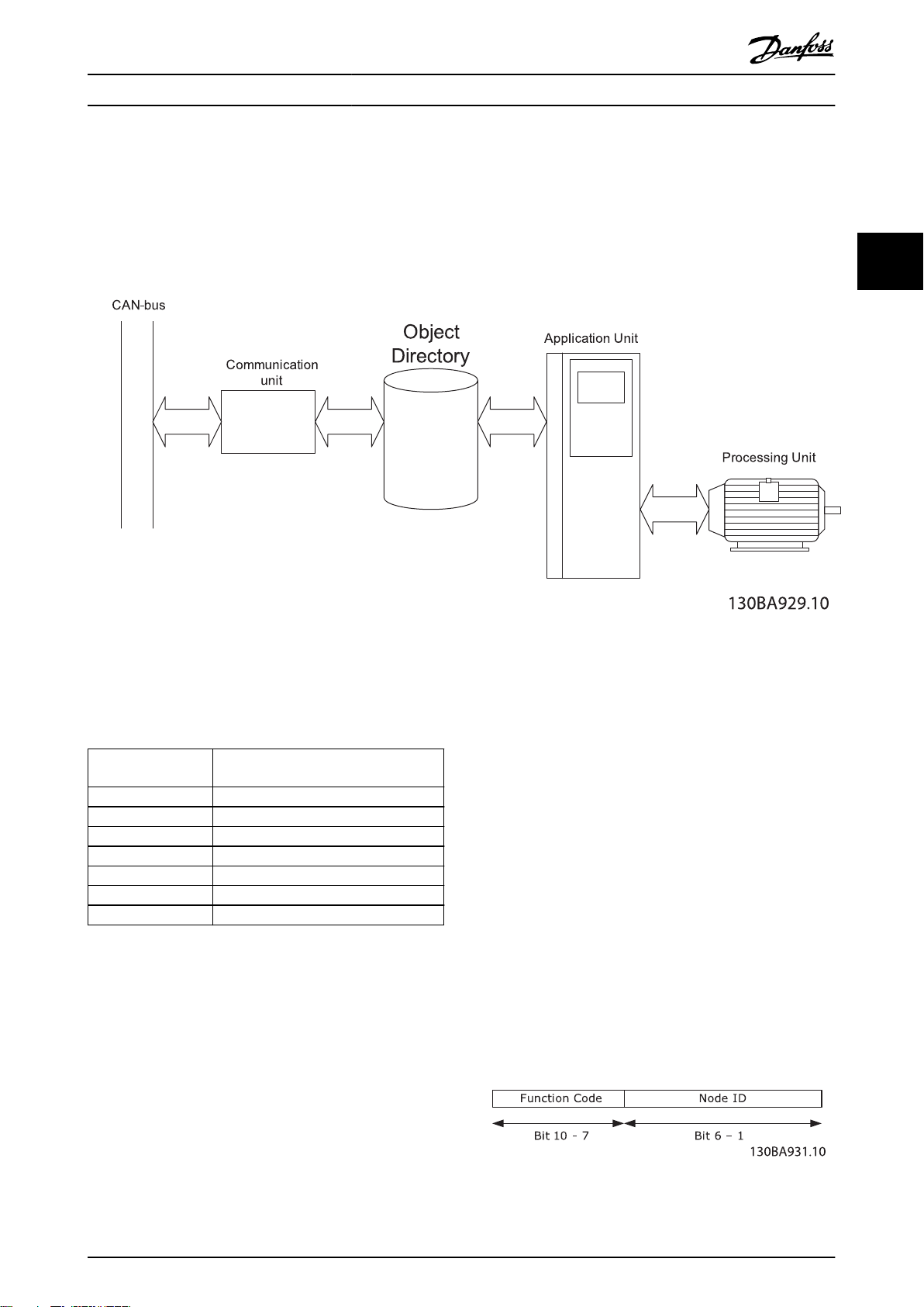
3.1.1 Object Model
Illustration 3.1 Functional Principle of CANopen Nodes
All information accessible via the CAN-bus is stored in the
object directory (OD).
The contents of the OD are organised in Table 3.1.
Object directory
index range
0000h Not used
0001h–025Fh Data types
0260h–0FFFh Reserved
1000h–1FFFh Communication object area
2000h–5FFFh Manufacturer-specic area
6000h–9FFFh Standardised device prole area
A000h–FFFFh Reserved
Table 3.1 Contents of the OD
For a complete overview of the supported objects in the
OD, refer to chapter 7 Object Directory.
Object type
3 3
3.1.2 Communication in CANopen
Communication with the frequency converter in CANopen
is achieved via service data objects (SDOs), process data
objects (PDOs), and network management (NMT).
PDOs represent real-time process data with high priority.
PDOs are only available if the node is in operational state.
SDOs represent non-time-critical data and are used to
congure the frequency converter. SDOs are only available
if node is in both operational and pre-operational state.
NMT functions monitor the network stability and include
synchronisation, detection of faults, and emergency
message transmission.
COB-Identiers (ID)
Each communication object has a unique identity (COB-ID)
comprising the function code and the node ID (node
address), see Illustration 3.2.
Illustration 3.2 COB-ID
MG92G102 Danfoss A/S © 06/2015 All rights reserved. 7
Page 10
Conguration
VLT® CANopen MCA 105
Object Function
code
(binary)
NMT 0000 0 –
SYNC 0001 125 (1005h)
33
Time stamp 0010 256 –
EMERGENCY 0001 129 (81h)–255
PDO1 (tx) 0011 385 (181h)–511
PDO1 (rx) 0100 513 (201h)–
PDO2 (tx) 0101 641 (281h)–
PDO2 (rx) 0110 769 (301h)–895
PDO3 (tx) 0111 897 (381h)–1023
PDO3 (rx) 1000 1025 (401h)–1151
PDO4 (tx) 1001 1153 (481h)–1279
PDO4 (rx) 1010 1281 (501h)–1407
SDO (tx) 1011 1409 (581h)–1535
SDO (rx) 1100 1537 (601h)–1663
NMT error control
(Nodeguarding)
1110 1793 (701h)–1919
Resulting COB-ID Communi-
cation
parameter in
OD
1014h
(FFh)
1800h
(1FFh)
1400h
639(27Fh)
1801h
767(2FFh)
1401h
(37Fh)
1802h
(3FFh)
1402h
(47Fh)
1803h
(4FFh)
1403h
(57Fh)
1200h – ...
(5FFh)
1200h – ...
(67Fh)
1016h, 1017h
(77Fh)
(100Eh)
The node must have a start network-command from an
NMT-master to enter the operational state.
In operational state, both SDO and PDO communication
are possible.
The NMT-state of the node is displayed with the green NS
LED:
Flashing = Pre-operational.
•
Solid on = Operational.
•
Single ash = Stopped.
•
A reset node or reset communication-command from the
NMT-master makes the node jump to initialisation state
and directly on to pre-operational state.
Table 3.2 Communication Object
Transmit and receive is always seen from the node’s point
of view:
RX = Nodes receiving data (Controller -> node)
•
TX = Nodes transmitting data (node -> controller)
•
Example:
COB-ID 383 = PDO3 transmit, from node address
•
3.
COB-ID 185 = PDO1 transmit, from node address
•
5.
COB-ID 604 = SDO receive, to node address 4.
•
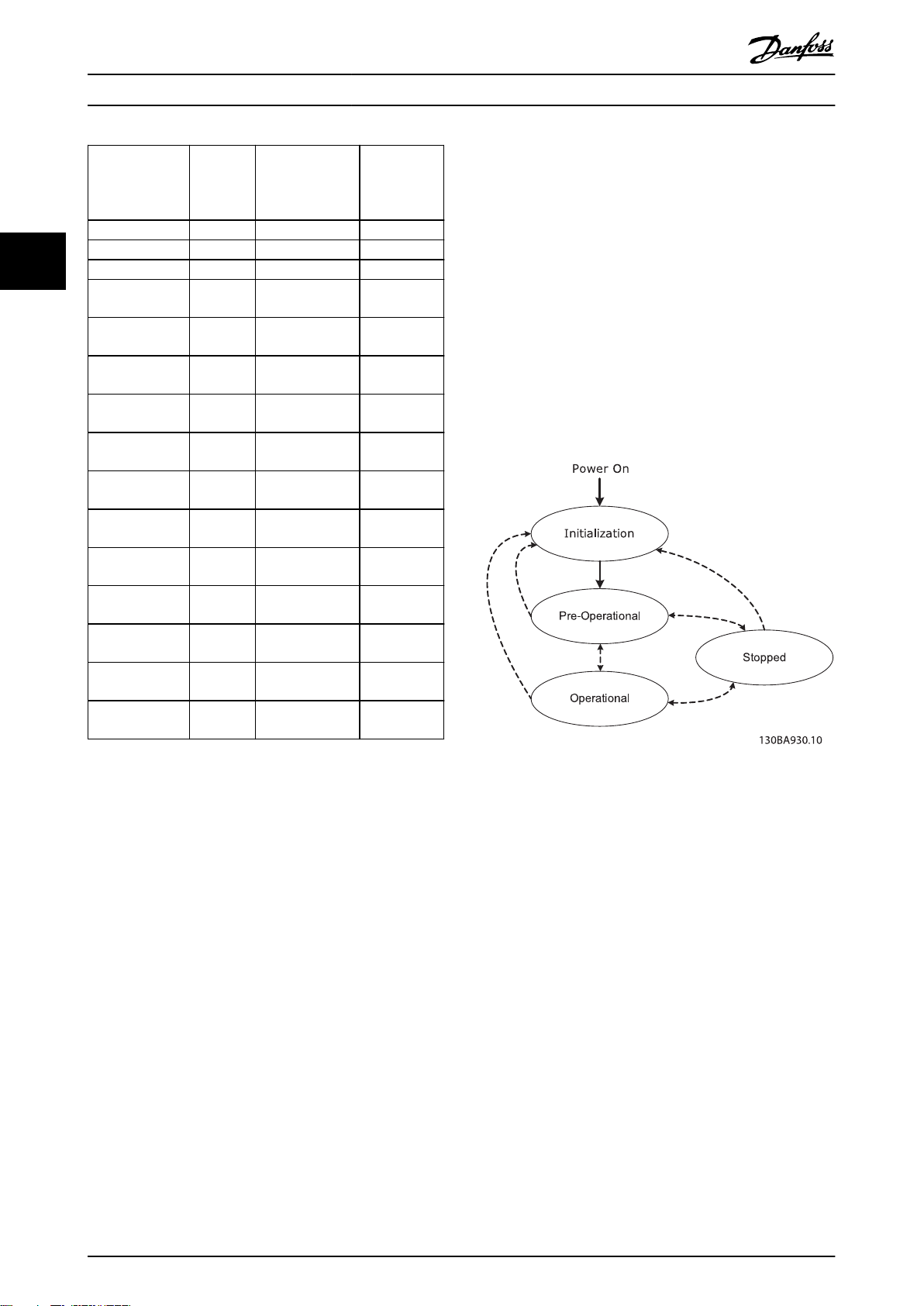
3.1.3 Controlling the Network
In each CANopen node, a state machine controls the
dierent states of the node.
After power-up, the node transmits a boot-up message
with the COB-ID: 700h + Node ID, and goes from initialisation to pre-operational state.
In this state, SDO communication is possible, but not PDO
communication.
Illustration 3.3 Controlling the Network
3.1.4 Error Control
CANopen oers 2 ways of error-control: Node guarding
and Heartbeat.
In node guarding, the NMT-master sends a remote-frame
(RTR) cyclically: 700 + node ID.
The node replies with its actual status.
The node (frequency converter) monitors the reception of
the RTR-frames, and thereby monitors the presence of the
NMT-master.
Congure the monitoring of the NMT-master via:
OD: 100C Guard time in [ms].
•
OD: 100D Life time factor.
•
If Guard Time x Life Time Factor has expired, the action
programmed in the parameter 8-04 Control Word Timeout
Function is executed.
8 Danfoss A/S © 06/2015 All rights reserved. MG92G102
Page 11
Conguration Programming Guide
The option can also be congured as heartbeat producer
via:
OD: 1017 Producer Heartbeat time [ms].
•
The MCA 105 option continuously transmits heartbeats
(RTRs with the frequency converters actual status) that can
be monitored by, for example, an NMT-master.
NOTICE
The MCA105 option does not support the heartbeat
consumer function.
Emergency object (EMCY)
The emergency object is used to signal error states, and is
sent automatically if an alarm in the frequency converter
occurs containing the data described in the following. If
the alarm is removed, another emergency telegram is sent
out with the contents 0, signalling the end of the
frequency converter’s alarm state.
Congure the behaviour of the EMCY object via
parameter 8-07 Diagnosis Trigger.
If parameter 8-07 Diagnosis Trigger is set to [0] Disable, the
EMCY is not sent at all. If it is set to Trigger alarms, it is
sent if an alarm occurs. If it is set to Trigger alarms and
warnings, it is sent if an alarm or a warning occurs.
OD 1014h contains the COB-ID of the node’s EMCY
message. This is xed to 80h + node ID.
The EMCY always consists of 8 bytes with the full data as
described in Table 3.3.
Byte 0 Byte 1 Byte 2 Byte 3 Byte 4 Byte 5 Byte 6 Byte 7
EMCY code*
(OD: 1003 [1])
Table 3.3 EMCY Consists of 8 Bytes with the Full Data
*= For more information on EMCY codes, refer to
chapter 8 Troubleshooting.
Bit 0 1, alarm word 1 has an active alarm (parameter 16-90)
Bit 1 1, alarm word 2 has an active alarm (parameter 16-91)
Bit 2 0, Reserved
Bit 3 1, warning word 1 has an active warning (parameter
Bit 4 1, warning word 2 has an active warning (parameter
Bit 5–7 0, reserved
16-92)
16-93)
OD:
1001h
Vendor-specic information
Bus error counters
The frequency converter contains 2 CAN-bus error
counters:
Parameter 10-05 Readout Transmit Error Counter
•
(TEC).
Parameter 10-06 Readout Receive Error Counter
•
(REC).
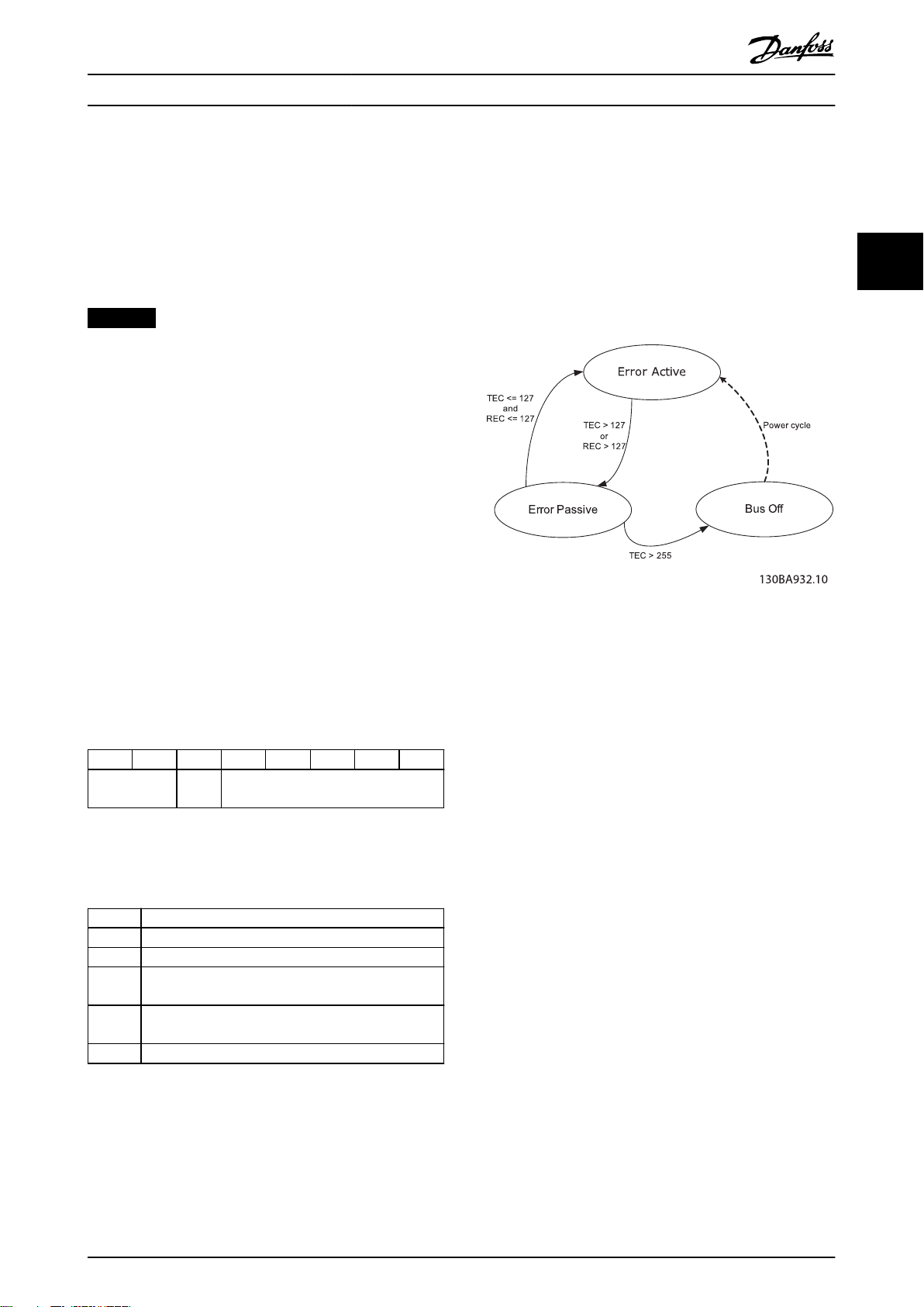
These counters determine the error-state of the CANopen
node.
Illustration 3.4 Bus Error Counters
TEC is incremented with 8 if a transmit-error occurs and
decremented with 1 if a transmission is successful.
REC is incremented with 1 if a receive error is detected (8
if the transmitting node is in error active-mode) and
decremented with 1 if a reception is successful.
In normal operation the node is in error active state.
If the TEC or REC exceeds the value: 127, the node enters
error passive state.
In Error passive state, the error-ag is not transmitted
dominantly but recessively.
This means that an error passive node, as receiver, cannot
block communication from other nodes.
A node in error passive state has a lower prioritised access
to the bus.
If the TEC exceeds 255 (248 + 8), the node enters bus o
state.
In bus o state, the MS LED turns solid red, and a warning
34 is issued.
Power-cycle the frequency converter to leave the bus o
state.
3 3
Table 3.4 Byte 3 Description
MG92G102 Danfoss A/S © 06/2015 All rights reserved. 9
Page 12
Conguration
VLT® CANopen MCA 105
3.1.5 SDO Communication
Restoring OD entries
To restore factory defaults, use OD index 1011h.
All CANopen objects and frequency converter parameters
can be accessed via SDOs (service data objects).
For a description of supported SDO abort codes, refer to
chapter 8 Troubleshooting.
33
COB-ID
Transmit SDO 1409 (581h)–1535 (5FFh) 580h + Node ID
Receive SDO 1537 (601h)–1663 (67Fh) 600h + Node ID
Table 3.5 COB-ID’s for SDO Communication
COB-ID CS OD-Index Sub-ind. Data
600+ID See following text 01 20 00 00 00 00 00
Table 3.6 Structure of a SDO-message (Request)
To restore default parameters the value “64616F6C” (load)
must be written to the appropriated sub-index in OD:
1011h
OD index Subindex Description
0 Number of entries
1011h
Table 3.10 Restoring OD Entries
* requires power cycle
1 Restore all parameters + OD entries*
2 Restore all communication parameters +
OD entries and restart
NOTICE
Frequency converter displays Alarm 80 “Drive initialised”
after restores.
The CS-eld contains the command and response
speciers. See Table 3.7 and Table 3.8.
Command CS
Write request 4 bytes 23h
Write request 2 bytes 2Bh
Write request 1 byte 2Fh
Read request (any) 40h
3.2 Congure the Master
3.2.1 EDS File
A large part area of the system conguration is the setting
of application-related parameters. EDS (electronic data
sheet) les simplify the setting up of most of the CANopen
congurable parameters. The EDS le contains all
Table 3.7 Command
supported communication-specic objects (OD 1000h
+ 1FFFh) and a selected number of manufacturer-specic
Response CS
Write response (any) 60h
Read response 4 bytes 43h
Read response 2 bytes 4Bh
Read response 1 byte 4Fh
Error response 80h
Table 3.8 Response
Saving OD entries
objects (frequency converter parameters) in the OD range
2000h–5FFFh.
Danfoss provides a generic English EDS le covering all
voltage and power sizes for o-line conguration.
Download the EDS le from www.danfoss.com/Busines-
sAreas/DrivesSolutions/Softwaredownload/
DDFieldbus_Setup_Files.htm.
In standard conguration, all parameters + OD entries are
stored in volatile (RAM) memory only. To store current
network conguration in non-volatile memory, use OD
index 1010h.
To save parameters, write the value 65766173 (save) to the
NOTICE
The EDS les do not contain all parameters but a
selected, limited number of parameters with generic
minimum, maximum, and default values.
appropriated sub-index in OD: 1010h.
OD index Subindex Description
0 Number of entries
1 Save all parameters + OD entries
1010h
Table 3.9 Saving OD Entries
10 Danfoss A/S © 06/2015 All rights reserved. MG92G102
2 Save all communication parameters + OD
entries
3 Reserved
4 Save edit set-up (Danfoss specic)
Page 13
130BA936.10
Conguration Programming Guide
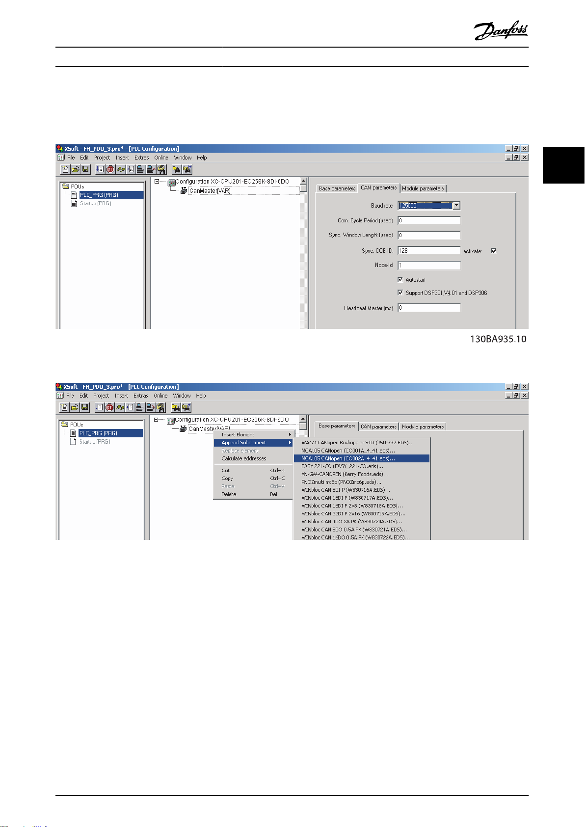
3.2.2 Conguring the CANopen Master
The following example shows the details in setting up the CANopen conguration on a Moeller XC-CPU201 PLC.
3 3
Illustration 3.5 Setting up the Baud Rate and Node-ID on the CanMaster (CANopen Scanner)
Illustration 3.6 Appending a CANopen Node, from EDS File Library, by Rght-clicking CanMaster
MG92G102 Danfoss A/S © 06/2015 All rights reserved. 11
Page 14
Conguration
VLT® CANopen MCA 105
33
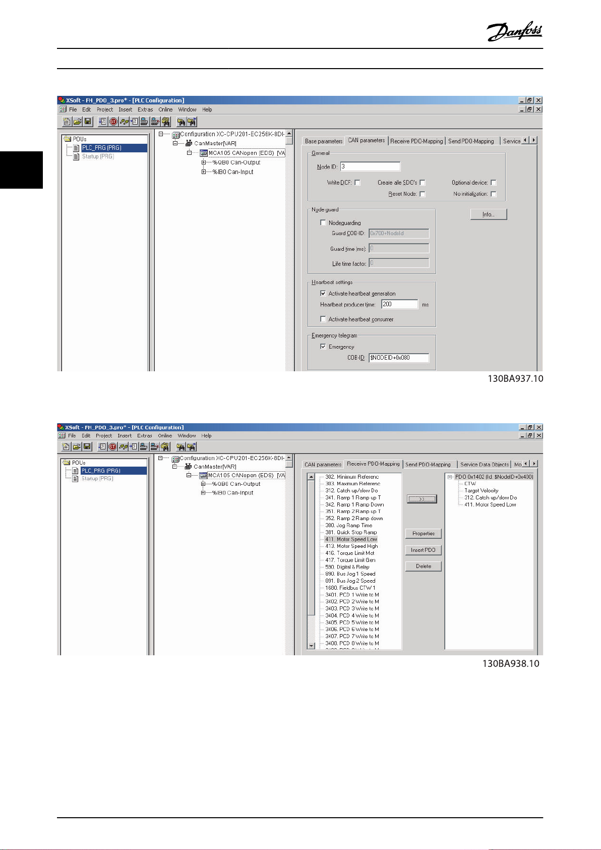
Illustration 3.7 Conguring the CAN Parameters like Node-ID, Node-guarding, Heartbeat, and so on, on Node
Illustration 3.8 Conguring Receive and Transmit PDO-mapping. Here PDO 1402 with Parameter 3-12 Catch up/slow Down Value and
Parameter 4-11 Motor Speed Low Limit [RPM]
12 Danfoss A/S © 06/2015 All rights reserved. MG92G102
Page 15

Conguration Programming Guide
Illustration 3.9 PLC Memory Mapping
3 3
3.3 Congure the Frequency Converter
3.3.1 Frequency Converter Parameters
Pay particular attention to the following parameters when
conguring an VLT® AutomationDrive FC 300 with a
CANopen interface. Refer to chapter 6 Parameters for more
details about each parameter.
Parameter 0-40 [Hand on] Key on LCP
If the [Hand On] key on the frequency converter is pressed,
control of the frequency converter via the CANopen
interface is disabled.
Parameter 8-02 Control Word Source
After initial power-up, the frequency converter automatically detects whether a
A, and sets parameter 8-02 Control Word Source to [Option
A]. If an option is added to, changed in, or removed from
an already commissioned frequency converter, it does not
change parameter 8-02 Control Word Source.
Parameter 8-10 Control Word
Select between the Danfoss FC Prole and the DSP 402
prole for CANopen. Refer to chapter 4 Control.
Parameter 8-01 Control Site and parameter 8-50 Coasting
Select to parameter 8-56 Preset Reference Select
Refer to chapter 4 Control.
Selection of how to gate the CANopen control commands
with digital input command of the control card.
Set Parameter 8-01 Control Site to: [2] Control word onlyor
[0] Digital and ctrl. word.
eldbus option is installed in slot
Prole
Parameter 8-03 Control Word Timeout Time to
parameter 8-05 End-of-Timeout Function
The reaction in the event of a bus timeout is set via these
parameters:
Parameter 10-01 Baud Rate Select
•
Default is 125 kbps.
Parameter 10-02 MAC ID
•
Default is 127.
NOTICE
When parameter 8-01 Control Site is set to [2] Control
word only, the settings in parameter 8-50 Coasting Select
to parameter 8-56 Preset Reference Select are overruled,
and all act on bus-control.
MG92G102 Danfoss A/S © 06/2015 All rights reserved. 13
Page 16

Control
VLT® CANopen MCA 105
4 Control
4.1 PDO Communication
The real-time data transfer is performed by process data objects (PDO).
The PDOs correspond to entries in the device object dictionary and provide the interface to the application objects.
44
Illustration 4.1 PDO Types
NOTICE
Control word (CTW), status word (STW), reference (REF), and Main Actual Value (MAV) are xed in PDO type 1–3. PDO
type 4 is free congurable.
All receive and transmit PDOs can be congured via the OD.
Map process data into receive and transmit PDOs via parameter 10-50 Process Data Cong Write. and parameter 10-51 Process
Data Cong Read. or via OD: 1600–1603 for receive PDOs and OD: 1A00–1A03 for transmit PDOs.
14 Danfoss A/S © 06/2015 All rights reserved. MG92G102
Page 17

Control Programming Guide
4.1.1 PDO Conguration
Index Name Sub
index
1400h
1401h
1402h
1403h
1600h
1601h
1602h
1603h
1st receive PDO (PDO 1)
2nd receive PDO (PDO 2)
3rd receive PDO (PDO 3)
4th receive PDO (PDO 4)
1st receive PDO mapping
(PDO 1)
COB-ID 201h–27Fh
2nd receive PDO mapping
(PDO 2)
COB-ID 301h–37Fh
3rd receive PDO mapping
(PDO 3)
COB-ID 401h–47Fh
4th receive PDO mapping
(PDO 4)
COB-ID 501h–57Fh
0 Number of entries.
1 COB ID.
2 Transmission type.
0 Number of entries.
1
0 Number of entries
1
2
0 Number of entries.
1
2
3
4
0 Number of entries.
1
2
3
4
Description Value Sub index 2 Transmission type
⇒
⇒
⇒
1st mapped object (60400010h control word, xed) (parameter 10-50 Process Data Cong
Write. [0])
1st mapped object (60400010h control word, xed) (parameter 10-50 Process Data Cong
Write. [0])
2nd mapped object (60420010h target velocity, xed) (parameter 10-50 Process Data Cong
Write. [1])
1st mapped object (60400010h control word, xed) (parameter 10-50 Process Data Cong
Write. [0])
2nd mapped object (60420010h target velocity, xed) (parameter 10-50 Process Data Cong
Write. [1])
3rd mapped object (2000h + parameter number) (parameter 10-50 Process Data Cong
Write. [2])
4th mapped object (2000h + parameter number) (parameter 10-50 Process Data Cong
Write. [3])
5th mapped object (2000h + parameter number) (parameter 10-50 Process Data Cong
Write. [4])
6th mapped object (2000h + parameter number) (parameter 10-50 Process Data Cong
Write. [5])
7th mapped object (2000h + parameter number) (parameter 10-50 Process Data Cong
Write. [6])
8th mapped object (2000h + parameter number) (parameter 10-50 Process Data Cong
Write. [7])
⇒
1...240 SYNC
1...240 SYNC
254...255 COS
254...255 COS
4 4
Table 4.1 Receive PDO Conguration
MG92G102 Danfoss A/S © 06/2015 All rights reserved. 15
Page 18

Control
VLT® CANopen MCA 105
Index Name Sub
0 Number of entries.
1800h
1801h
1802h
1803h
44
1A00h
1A01h
1A02h
1A03h
1st transmit PDO (PPO 1)
2nd transmit PDO (PPO 2)
3rd transmit PDO (PPO 3)
4th transmit PDO (PPO 4)
5 Event timer.
1st transmit PDO mapping
(PDO 1)
COB-ID 181h–1FFh
2nd transmit PDO mapping
(PDO 2)
COB-ID 281h–2FFh
3rd transmit PDO mapping
(PDO 3)
COB-ID 381h–3FFh
4th transmit PDO mapping
(PDO 4)
COB-ID 481h–4FFh
1
1
2
1
2
3
4
1
2
3
4
Description Value sub index 2 Transmission type
index
⇒
COB ID.
1
Transmission type.
2
Inhibit time.
3
Reserved.
4
0 Number of entries.
1st mapped object (60410010h status word, xed) (parameter 10-51 Process Data Cong
Read. [0])
0 Number of entries.
1st mapped object (60410010h status word, xed) (parameter 10-51 Process Data Cong
Read. [0])
2nd mapped object (60440010h control eort, xed) (parameter 10-51 Process Data Cong
Read. [1])
0 Number of entries.
1st mapped object (60410010h status word, xed) (parameter 10-51 Process Data Cong
Read. [0])
2nd mapped object (60440010h control eort, xed) (parameter 10-51 Process Data Cong
Read. [1])
3rd mapped object (2000h + parameter number) (parameter 10-51 Process Data Cong
Read. [2])
4th mapped object (2000h + parameter number) (parameter 10-51 Process Data Cong
Read. [3])
0 Number of entries.
5th mapped object (2000h + parameter number) (parameter 10-51 Process Data Cong
Read. [4])
6th mapped object (2000h + parameter number) (parameter 10-51 Process Data Cong
Read. [5])
7th mapped object (2000h + parameter number) (parameter 10-51 Process Data Cong
Read. [6])
8th mapped object (2000h + parameter number) (parameter 10-51 Process Data Cong
Read. [7])
⇒
⇒
⇒
⇒
⇒
0 SYNC, non-cyclic
0 SYNC, non-cyclic
1...240 SYNC
1...240 SYNC
254...255 COS
254...255 COS
Table 4.2 Transmit PDO Conguration
16 Danfoss A/S © 06/2015 All rights reserved. MG92G102
Page 19

Control Programming Guide
4.1.2 PDO Mapping Syntax
Sub-index 1–4 contains the mapped objects.
Example: Object 6041 status word is xed in PDO 1 and
PDO 2 as the rst transmit-word.
That is, OD 1A00h and 1A01h sub-index 1 holds the value
of 60410010 (6041 = object number, 00 = sub-index, 10 =
length of data = 16 bits)
Example: To map parameter 16-14 Motor current (32-bit
data) in PDO 3, it must be mapped in 2 PDO-words.
Parameter 16-14 Motor current is according to manufacturer
object 264E.
1A02h [3] = 264E0020 (264E = object number, 00 = subindex, 20 = length of data = 32 bits)
1A02h [4] = 264E0020 (264E = object number, 00 = subindex, 20 = length of data = 32 bits)
4.1.3 PDO Transmission Modes
Sub-index 2 contains the setting of the transmission mode.
The following PDO transmission modes are distinguished:
Synchronous transmission.
•
Asynchronous transmission.
•
Remotely requested
The transmission of asynchronous PDO’s may be initiated
on receipt of a remote request initiated by another device.
Transmission
type
0 x x
1–240 x x
241–251 Reserved
252
253
254 x
255 x
Table 4.3 PDO Transmission
PDO transmission
Cyclic Acyclic Synchronous Asynchronous RTR
only
Not supported
4.1.5 Inhibit Time
Sub-index 3 contains the inhibit time.
This time denes a minimum interval for PDO transmission.
The value is dened as multiple of 0.1 ms.
Default value is 300 = 30 ms.
Minimum value is 0.
Maximum value is 32767 = 3.2 s.
Data length = 2 bytes.
4 4
4.1.4 PDO Triggering Modes
The CANopen communication prole distinguishes 2
message triggering modes:
Event driven.
•
Remotely requested.
•
Event driven
Message transmission is triggered by the occurrence of an
object-specic event.
For synchronous PDOs, this is the expiration of the
specied transmission period, synchronised by the
reception of the SYNC object.
For acyclically transmitted synchronous PDOs and
asynchronous PDO’s, the triggering of a message
transmission is an application-specic event specied in
the device prole.
4.1.6 Event Timer
Sub-index 5 contains the inhibit time for transmit PDOs.
If an event timer is congured for a TPDO (value not equal
to 0), the elapsed timer causes the transmission of this
TPDO.
The event timer can be congured as multiple of 1 ms.
Default value is 0.
Maximum value is 32767 = 32 s.
Data length = 2 bytes.
MG92G102 Danfoss A/S © 06/2015 All rights reserved. 17
Page 20

Control
VLT® CANopen MCA 105
4.2 Control Prole
4.2.1 Control Word Prole 8–10
8–10 Control Prole
In parameter 8-10 Control Word Prole, it is possible to select:
Option: Function:
[0] * FC prole
44
4.2.2 DSP 402 State Transitions
8–10 Control Prole
In parameter 8-10 Control Word Prole, it is possible to select:
Option: Function:
[5] CANopen DSP
[0] FC Prole is the default control prole for VLT frequency
converters, whereas [5] CANopen DSP 402 is the CiA
standardised control prole, featuring the special DSP 402
transition state machine.
Illustration 4.2 DSP 402 State Machine
18 Danfoss A/S © 06/2015 All rights reserved. MG92G102
Page 21

Control Programming Guide
Transition State Control word Status word Action
– Start condition 0000 0000
0
1
2
3
4
5
6
7
8
9
10
11
12
13
14
15
16
Start-up⇒Not ready to switch on
Not ready to switch on⇒ Switch on disabled
Switch on disable⇒Ready to switched on
Ready to switch on⇒Switched on
Switched on⇒Operation enabled
Operation enabled⇒Switched on
Switched on⇒Ready to switch on
Ready to switch on⇒Switch on disable
Operation enable⇒Ready to switch on
Operation enable⇒Switch on disable
Switched on⇒Switched on disable
Operation enabled⇒Quick stop active
Quick stop activ⇒Switch on disabled
All states⇒Fault reaction active
Fault reaction active⇒Fault
Fault⇒Switch on disabled
Quick stop active⇒Operation enable (not
supported)
0000 0200
0000, 0001 0240
0006 0231
0007 0233
000F 0237
0007 0233
0006 0231
0001, 0000 0240
0006 0231
0001, 0000 0240
0001, 0000 0240
0002 0207
0001, 0000 0240
xxxx 023F
xxxx
0000 0240
023F (0238
by InterBus)
Motor ramps to 0 RPM with programmed
ramp-down parameter.
The power section is switched o immediately,
and the motor is free to rotate if unbraked.
The power section is switched o immediately,
and the motor is free to rotate if unbraked.
The power section is switched o immediately,
and the motor is free to rotate if unbraked.
The motor ramps to 0 RPM with programmed
quick-ramp parameter.
The power section is switched o immediately,
and the motor is free to rotate if unbraked.
4 4
Table 4.4 DSP 402 State Transitions
MG92G102 Danfoss A/S © 06/2015 All rights reserved. 19
Page 22

Speed ref.CTW
Master-follower
130BA274.11
15 14 13 12 11 10 9 8 7 6 5 4 3 2 1 0
Bit
no.:
Control
VLT® CANopen MCA 105
4.3 DSP 402 Control Prole
Bit 05, Freeze output frequency/run enable:
Bit 05 = 0 means that the given output frequency is
4.3.1 Control Word According to DSP 402
Prole
(parameter 8-10 = DSP 402 prole)
maintained even if the reference is changed.
Bit 05 = 1 means that the frequency converter is again
able to regulate, and the given reference is followed.
Bit 06, Ramp stop/start:
Bit 06 = 0 The frequency converter controls the motor
down to stop.
Bit 01 = 1 A start command to the frequency converter is
44
given.
Bit 07, No function/reset:
Illustration 4.3 Control Word
Reset of trip.
Bit 07 = 0 means that there is no reset.
Bit 07 = 1 means that a trip is reset.
Bit Bit value = 0 Bit value = 1
00 Switch o Switch on
01 Disable voltage Enable voltage
02 Quick stop Run
03 Disable operation Enable operation
04 Disable ramp Enable ramp
05 Freeze Run enable
06 Ramp stop Start
07 No function Reset
08 Reserved
09 Reserved
10 Reserved
11 Jog 1 OFF Jog 1 ON
12 Reserved
13 Setup select (LSB)
14 Setup select (MSB)
15 Forward Reversing
Bit 08, 09, and 10:
DSP402 reserved.
Bit 11, Jog 1 OFF/ON:
Activation of pre-programmed speed in parameter 8-90 Bus
Jog 1 Speed (bus jog 1).
Jog 1 is only possible if bit 04 = 0, and bits 00–03 = 1.
Bit 12:
Danfoss reserved.
Bits 13/14, Selection of setup:
Bits 13 and 14 are used for selecting among the 4 menu
set-ups in accordance with Table 4.6.
Set-up Bit 14 Bit 13
0 0 1
0 1 2
1 0 3
1 1 4
Table 4.5 Control Bits
Explanation of the control bits
Bit 00, Switch o/on:
Bit 00 = 0 executes transition 2, 6, or 8.
Bit 00 = 1 executes transition 3.
Bit 01, Disable/enable voltage:
Bit 01 = 0 executes transition 9, 10, or 12.
Bit 01 = 1 enables voltage.
Bit 02, Quick stop/run:
Bit 02 = 0 execute transition 7, 10, or 11.
Bit 02 = 1 Quick stop not active.
Bit 03, Disable/enable operation:
Bit 03 = 0 executes transition 5.
Bit 03 = 1 Enables operation.
Bit 04, Quick-stop/ramp:
Bit 04 = 0 executes transition 7 or 11, Quick stop.
Bit 04 = 1 Enables ramp.
20 Danfoss A/S © 06/2015 All rights reserved. MG92G102
Table 4.6 4 Menu Set-ups
Bit 15, Forward/reversing:
Bit 15 = "0" leads to no reversing.
Bit 15 = "1" leads to reversing.
NOTICE
In factory setting, reversing is set to [0] Digital input in
parameter 8-54 Reversing Select.
Page 23

Output freq.STW
Bit
no.:
Follower-master
15 14 13 12 11 10 9 8 7 6 5 4 3 2 1 0
130BA273.11
Control Programming Guide
4.3.2 Status Word According to DSP 402
Illustration 4.4 Status Word
Bit Bit value = 0 Bit value = 1
00 Not ready to switch
01 Switched OFF Switched ON
02 Operation disabled Operation enabled
03 No malfunction Malfunction
04 Voltage disabled Voltage enabled
05 Quick stop Run
06 Switch on disable Switch on enable
07 No warning Warning
08 Reserved
09 Remote disabled Remote enabled
10 Setpoint not reached Setpoint reached
11 Speed limit not
12 Reserved
13 Reserved
14 Not running Running
15 Reserved
Table 4.7 Status Bits
Explanation of the status bits
Bit 00, Not ready to switch on/ready to switch on:
Bit 00 = 0 state less than Ready to switch on.
Bit 00 = 1 state at least = Ready to Switch on.
Bit 01, Switch o/switch on:
Bit 00 = 0 state less than switched on.
Bit 00 = 1 state at least = switched on.
Bit 02, Operation disable/operation enable:
Bit 00 = 0 state less than operation enable.
Bit 00 = 1 state at least = operation enable.
Bit 03, No fault/trip:
Bit 03 = 0 means that the frequency converter is not in a
fault condition.
Bit 03 = 1 means that the frequency converter has tripped
and needs a reset signal to run.
Bit 04, Voltage disable/voltage enable:
Bit 04 = 0 means that control word bit 01 = 1.
Bit 04 = 1 means that control word bit 01 = 0.
Bit 05, Quick stop/run:
Bit 05 = 0 means that control word bit 02 = 1.
Bit 05 = 1 means that control word bit 02 = 0.
MG92G102 Danfoss A/S © 06/2015 All rights reserved. 21
Prole
ON
active
Bit 06, Start enable/start disable:
Bit 06 = 0 state is not switch on disable.
Bit 06 = 1 state is switch on enable.
Bit 07, No warning/warning:
Bit 07 = 0 means that there is no warning. situation.
Bit 07 = 1 means that a warning has occurred.
Bit 08
Danfoss reserved.
Bit 09, Remote disable/remote enable:
4 4
Bit 09 = 0 means that the frequency converter has been
stopped with the [stop] key on the LCP, or that [Local] has
been selected in parameter 3-13 Reference Site.
Ready to switch ON
Bit 09 = 1 means that it is possible to control the
frequency converter via the serial port.
Bit 10, Setpoint not reached/setpoint reached:
Bit 10 = 0 means that the actual motor speed is dierent
from the speed reference set. This can be the case while
the speed is ramped up/down during start/stop.
Bit 10 = 1 means that the present motor speed equals the
speed reference set.
Bit 11, Speed limit not active/speed limit active:
Bit 11 = 0 means that the output frequency is out of the
range set in parameter 4-11 Motor Speed Low Limit [RPM]/
parameter 4-12 Motor Speed Low Limit [Hz] or
Speed limit active
parameter 4-13 Motor Speed High Limit [RPM]/
parameter 4-14 Motor Speed High Limit [Hz].
Bit 11 = 1 means that the output frequency is within the
mentioned range.
Bit 12
DSP 402 reserved.
Bit 13
DSP 402 reserved.
Bit 14, Running/not running:
Bit 14 = 0 means that the motor is not running.
Bit 14 = 1 means that the frequency converter has a valid
start signal or that the output frequency is greater than 0
Hz.
Bit 15
Danfoss reserved.
Page 24

Speed ref.CTW
Master-follower
130BA274.11
15 14 13 12 11 10 9 8 7 6 5 4 3 2 1 0
Bit
no.:
Control
VLT® CANopen MCA 105
4.4 Danfoss FC control prole
4.4.1 Control Word according to FC Prole
(parameter 8-10 = FC prole)
44
Illustration 4.5 Control Word
Bit Bit value = 0 Bit value = 1
00 Reference value External selection lsb
01 Reference value External selection msb
02 DC brake Ramp
03 Coasting No coasting
04 Quick stop Ramp
05 Hold output
frequency
06 Ramp stop Start
07 No function Reset
08 No function Jog
09 Ramp 1 Ramp 2
10 Data invalid Data valid
11 No function Relay 01 active
12 No function Relay 04 active
13 Parameter set-up Selection lsb
14 Parameter set-up Selection msb
15 No function Reverse
Table 4.8 Control Bits
Explanation of the control bits
Bits 00/01
Bits 00 and 01 are used to select between the 4 reference
values, which are pre-programmed in parameter 3-10 Preset
Reference according to Table 4.9.
Set-up Bit 14 Bit 13
1 0 0
2 0 1
3 1 0
4 1 1
Table 4.9 Set-up
Use ramp
Bit 02, DC brake:
Bit 02 = 0 leads to DC brake and stop. Braking current and
duration are set in parameter 2-01 DC Brake Current and
parameter 2-02 DC Braking Time.
Bit 02 = 1 leads to ramping.
Bit 03, Coasting:
Bit 03 = 0 causes the frequency converter to immediately
release the motor (the output transistors are "shut o"), so
that it coasts to a standstill.
Bit 03 = 1 enables the frequency converter to start the
motor if the other starting conditions are fullled.
NOTICE
In parameter 8-50 Coasting Select, a selection is made to
dene how bit 03 gates with the corresponding function
on a digital input.
Bit 04, Quick stop:
Bit 04 = 0 causes a stop, in which the motor speed is
ramped down to stop via parameter 3-81 Quick Stop Ramp
Time.
Bit 05, Hold output frequency:
Bit 05 = 0 causes the present output frequency (in Hz) to
freeze. The frozen output frequency can then be changed
only with the digital inputs (parameter 5-10 Terminal 18
Digital Input to parameter 5-15 Terminal 33 Digital Input)
programmed to speed up and speed down.
NOTICE
If freeze output is active, the frequency converter can
only be stopped by the following:
Bit 03 Coasting stop.
•
Bit 02 DC braking.
•
Digital input (parameter 5-10 Terminal 18 Digital
•
Input to parameter 5-15 Terminal 33 Digital
Input) programmed to DC braking, coasting stop
or reset and coasting stop.
Bit 06, Ramp stop/start:
Bit 06 = 0 causes a stop, in which the motor speed is
ramped down to stop via the selected ramp-down
parameter.
Bit 06 = 1 permits the frequency converter to start the
motor, if the other starting conditions are fullled.
NOTICE
In parameter 8-56 Preset Reference Select a selection is
made to dene how bit 00/01 gates with the
corresponding function on the digital inputs.
NOTICE
In parameter 8-53 Start Select a selection, is made to
dene how bit 06 Ramp stop/start gates with the
corresponding function on a digital input.
22 Danfoss A/S © 06/2015 All rights reserved. MG92G102
Page 25

Output freq.STW
Bit
no.:
Follower-master
15 14 13 12 11 10 9 8 7 6 5 4 3 2 1 0
130BA273.11
Control Programming Guide
Bit 07, Reset:
Bit 07 = 0 does not cause a reset.
Bit 07 = 1 causes the reset of a trip. Reset is activated on
the signal’s leading edge, for example, when changing
from logic 0 to logic 1.
Bit 08, Jog:
Bit 08 = 1 causes the output frequency to be determined
by parameter 3-19 Jog Speed [RPM].
Bit 09, Selection of ramp 1/2:
Bit 09 = 0 means that ramp 1 is active
(parameter 3-40 Ramp 1 Type to parameter 3-47 Ramp 1 S-
ramp Ratio at Decel. Start).
Bit 09 = 1 means that ramp 2 (parameter 3-50 Ramp 2 Type
to parameter 3-57 Ramp 2 S-ramp Ratio at Decel. Start) is
active.
Bit 10, Data not valid/data valid:
Is used to tell the frequency converter whether the control
word is to be used or ignored.
Bit 10 = 0 causes the control word to be ignored.
Bit 10 = 1 causes the control word to be used. This
function is relevant, because the control word is always
contained in the telegram, regardless of which type of
telegram is used, for example, it is possible to turn o the
control word if it is not to be used it with updating or
reading parameters.
Bit 11, Relay 01:
Bit 11 = 0 Relay 01 is not activated.
Bit 11 = 1 Relay 01 activated, provided control word bit 11
is selected in parameter 5-40 Function Relay.
Bit 12, Relay 04:
Bit 12 = 0 Relay 04 is not activated.
Bit 12 = 1 Relay 04 is activated, provided control word bit
12 has been selected in parameter 5-40 Function Relay.
Bit 13/14, Selection of set-up:
Bits 13 and 14 are used to select from the four menu setups according to Table 4.10.
Set-up Bit 14 Bit 13
1 0 0
2 0 1
3 1 0
4 1 1
NOTICE
In parameter 8-55 Set-up Select, a selection is made to
dene how bit 13/14 gates with the corresponding
function on the digital inputs.
Bit 15 Reverse:
Bit 15 = 0 causes no reversing.
Bit 15 = 1 causes reversing.
NOTICE
In the factory setting reversing is set to digital in
parameter 8-54 Reversing Select.
Bit 15 causes reversing only when Ser. communication,
Logic or, or Logic and is selected.
4.4.2 Status Word according to FC Prole
(parameter 8-10 = FC prole)
Illustration 4.6 Status Word
’Bit Bit value = 0 Bit value = 1
00 Control not ready Control ready
01 Frequency converter
not ready
02 Coasting Enable
03 No error Trip
04 No error Error (no trip)
05 Reserved -
06 No error Trip lock
07 No warning Warning
08
Speed ≠ reference
09 Local operation Bus control
10 Out of frequency
limit
11 No operation In operation
12 Frequency converter
ok
13 Voltage ok Voltage exceeded
14 Torque ok Torque exceeded
15 Timer ok Timer exceeded
Frequency converter ready
Speed = reference
Frequency limit ok
Stopped, auto start
4 4
Table 4.10 Selection of Set-up
The function is only possible when [9] Multi set-ups are
selected in parameter 0-10 Active Set-up
MG92G102 Danfoss A/S © 06/2015 All rights reserved. 23
Table 4.11 Status Bits
Page 26

Control
VLT® CANopen MCA 105
Explanation of the status bits
Bit 00, Control not ready/ready:
Bit 00 = 0 means that the frequency converter has tripped.
Bit 00 = 1 means that the frequency converter controls are
ready, but that the power component is not necessarily
receiving any power supply (in case of 24 V external
supply to controls).
Bit 01, Frequency converter ready:
44
Bit 01 = 1. The frequency converter is ready for operation,
but there is an active coasting command via the digital
inputs or via serial communication.
Bit 02, Coasting stop:
Bit 02 = 0 The frequency converter has released the motor.
Bit 02 = 1 The frequency converter can start the motor
when a start command is given.
Bit 03, No error/trip:
Bit 03 = 0 means that the frequency converter is not in
fault mode.
Bit 03 = 1 means that the frequency converter is tripped,
and that a reset signal is required to re-establish operation.
Bit 04, No error/error (no trip):
Bit 04 = 0 means that the frequency converter is not in
fault mode.
Bit 04 = 1 means that there is a frequency converter error
but no trip.
Bit 05, Not used:
Bit 05 is not used in the status word.
Bit 06, No error/triplock:
Bit 06 = 0 means that the frequency converter is not in
fault mode.
Bit 06 = 1 means that the frequency converter is tripped,
and locked.
Bit 07, No warning/warning:
Bit 07 = 0 means that there are no warnings.
Bit 07 = 1 means that a warning has occurred.
Bit 08, Speed ≠ reference/speed = reference:
Bit 08 = 0 means that the motor is running, but that the
present speed is dierent from the preset speed reference.
It might, for example, be the case while the speed is being
ramped up/down during start/stop.
Bit 08 = 1 means that the present motor present speed
matches the preset speed reference.
Bit 09, Local operation/bus control:
Bit 09 = 0 means that [STOP/RESET] is pressed on the
control unit, or that local control in
parameter 3-13 Reference Site is selected. It is not possible
to control the frequency converter via serial communication.
Bit 09 = 1 means that it is possible to control the
frequency converter via the eldbus/ serial communication.
Bit 10, Out of frequency limit:
Bit 10 = 0 if the output frequency has reached the value in
parameter 4-11 Motor Speed Low Limit [RPM] or
parameter 4-13 Motor Speed High Limit [RPM].
Bit 10 = 1 means that the output frequency is within the
dened limits.
Bit 11, No operation/in operation:
Bit 11 = 0 means that the motor is not running.
Bit 11 = 1 means that the frequency converter has a start
signal or that the output frequency is greater than 0 Hz.
Bit 12, Frequency converter OK/stopped, auto start:
Bit 12 = 0 means that there is no temporary overtemperature on the inverter.
Bit 12 = 1 means that the inverter has stopped because of
overtemperature, but that the unit has not tripped and will
resume operation once the overtemperature stops.
Bit 13, Voltage OK/limit exceeded:
Bit 13 = 0 means that there are no voltage warnings.
Bit 13 = 1 means that the DC voltage in the frequency
converter’s DC link is too low or too high.
Bit 14, Torque OK/limit exceeded:
Bit 14 = 0 means that the motor current is lower than the
torque limit selected in parameter 4-18 Current Limit.
Bit 14 = 1 means that the torque limit in
parameter 4-18 Current Limit has been exceeded.
Bit 15, Timer OK/limit exceeded:
Bit 15 = 0 means that the timers for motor thermal
protection and frequency converter thermal protection,
respectively, have not exceeded 100%.
Bit 15 = 1 means that 1 of the timers has exceeded 100%.
24 Danfoss A/S © 06/2015 All rights reserved. MG92G102
Page 27

Control Programming Guide
4.5 Reference Handling
In both FC prole and CANopen DSP 402, the reference is scaled as a normalised relative value in percent. The value is
transmitted in hexadecimal:
0% = 0 hex.
•
100% = 4000 hex.
•
-100% = C000 hex.
•
Depending of the setting of parameter 3-00 Reference Range, the reference is scaled from – Maximum to + Maximum or from
Minimum to Maximum.
Illustration 4.7 Reference Handling
4 4
The actual reference [Ref. %] in the frequency converter
depends on the settings in the following parameters:
Parameter 1-23 Motor Frequency.
•
Parameter 1-25 Motor Nominal Speed.
•
Parameter 3-02 Minimum Reference.
•
Parameter 3-03 Maximum Reference.
•
All references provided to the frequency converter are
added to the total reference value.
If a reference is to be controlled by the eldbus only,
ensure that all other reference inputs are 0.
This means that digital and analog input terminals should
not be used for reference signals.
Maintain the default setting (0%) for preset references in
parameter 3-10 Preset Reference.
If the bus speed reference is negative, and the control
word contains a run reverse signal, the frequency converter
runs clockwise (- - is +).
MAV is scaled in the same way as the reference.
MG92G102 Danfoss A/S © 06/2015 All rights reserved. 25
Page 28

Parameter Access
VLT® CANopen MCA 105
5 Parameter Access
5.1 Danfoss Specic Objects (2000h-5FFFh)
All frequency converter parameters are accessible as ODentries:
OD index = Frequency converter parameter + 2000h.
Frequency converter parameter CANopen OD index
1 2001h
55
2 2002h
... ...
0-10 200Ah
0-11 200Bh
... ...
1-00 2064h
1-01 2065h
... ...
10-00 23E8h
10-01 23E9h
... ...
Table 5.1 Example of Converting of Frequency Converter
Parameters
Access the indexed parameters by accessing the
appropriate subindex of the OD index.
26 Danfoss A/S © 06/2015 All rights reserved. MG92G102
Page 29

Parameters Programming Guide
6 Parameters
8-01 Control Site
Option: Function:
The setting in this parameter overrides the
settings in parameter 8-50 Coasting Select to
parameter 8-56 Preset Reference Select.
[0] Digital and
ctrl.word
[1] Digital only Control by using digital inputs only.
[2] Controlword
only
Control by using both digital input and
control word.
Control by using control word only.
8-02 Control Word Source
Option: Function:
NOTICE
This parameter cannot be adjusted
while the motor runs.
Select the source of the control word: 1 of 2
serial interfaces or 4 installed options. During
initial power-up, the frequency converter
automatically sets this parameter to [3] Option
A, if it detects a valid
in slot A. When the option is removed, the
frequency converter detects a conguration
change, sets parameter 8-02 Control Word
Source to default setting RS485, and trips. If
an option is installed after initial power-up,
the setting of parameter 8-02 Control Word
Source does not change, but the frequency
converter trips and shows: Alarm 67, Option
Changed.
When retrotting a bus option into a
frequency converter that did not have a bus
option installed earlier, change the control to
bus-based. This change is required for safety
reasons to avoid an unintended change.
[0] None
[1] FC RS485
[2] FC USB
[3] Option A
[4] Option B
[5] Option C0
[6] Option C1
[30] External Can
8-03 Control Word Timeout Time
Range: Function:
1 s* [ 0.1 -
18000 s]
Enter the maximum time expected to pass
between the reception of 2 consecutive
telegrams. If this time is exceeded, it indicates
eldbus option installed
8-03 Control Word Timeout Time
Range: Function:
that the telegram communication has stopped.
The function selected in parameter 8-04 Control
Word Timeout Function is then carried out. A
valid control word triggers the timeout counter.
8-04 Control Word Timeout Function
Select the timeout function. The timeout function activates when
the control word fails to be updated within the time period
specied in parameter 8-03 Control Word Timeout Time.
Option: Function:
NOTICE
To change the set-up after a timeout,
congure as follows:
Set parameter 0-10 Active Set-up to [9]
Multi set-up and select the relevant
link in parameter 0-12 This Set-up
Linked to.
[0] O Resumes control via eldbus (eldbus or
standard), using the most recent control
word.
[1] Freeze output Freezes output frequency until communi-
cation resumes.
[2] Stop Stops with auto restart when communi-
cation resumes.
[3] Jogging Runs the motor at jog frequency until
communication resumes.
[4] Max. speed Runs the motor at maximum frequency until
communication resumes.
[5] Stop and trip Stops the motor, then resets the frequency
converter to restart:
Via the eldbus.
•
Via [Reset].
•
Via a digital input.
•
[7] Select setup1Changes the set-up after reestablishment of
communication following a control word
timeout. If communication resumes after a
timeout, parameter 8-05 End-of-Timeout
Function denes whether to resume the set-
up used before the timeout, or to retain the
set-up endorsed by the time-out function.
[8] Select setup2See [7] Select set-up 1.
[9] Select setup3See [7] Select set-up 1.
6
6
MG92G102 Danfoss A/S © 06/2015 All rights reserved. 27
Page 30

Parameters
VLT® CANopen MCA 105
6
8-04 Control Word Timeout Function
Select the timeout function. The timeout function activates when
the control word fails to be updated within the time period
specied in parameter 8-03 Control Word Timeout Time.
Option: Function:
[10] Select setup4See [7] Select set-up 1.
[26] Trip
8-05 End-of-Timeout Function
Option: Function:
Select the action after receiving a valid control
word following a timeout. This parameter is
active only when parameter 8-04 Control
Timeout Function is set to:
[7] Set-up 1.
•
[8] Set-up 2.
•
[9] Set-up 3.
•
[10] Set-up 4.
•
[0] Hold set-upRetains the set-up selected in
parameter 8-04 Control Timeout Function and
shows a warning until parameter 8-06 Reset
Control Timeout toggles. Then the frequency
converter resumes its original set-up.
[1] * Resume
set-up
Resumes the set-up active before the timeout.
8-06 Reset Control Word Timeout
This parameter is active only when [0] Hold set-up has been
selected in parameter 8-05 End-of-Timeout Function.
Option: Function:
[0] * Do not reset Retains the set-up specied in
parameter 8-04 Control Word Timeout Function,
following a control word timeout.
[1] Do reset Returns the frequency converter to the
original set-up following a control word
timeout. The frequency converter performs
the reset and then immediately reverts to the
[0] Do not reset setting.
8-07 Diagnosis Trigger
Option: Function:
This parameter enables and controls the
frequency converter diagnosis function and
permits expansion of the diagnosis data to 24
byte.
8-07 Diagnosis Trigger
Option: Function:
•
•
•
The content of the extended diagnosis frame is
as follows:
Byte Content Description
0 - 5 Standard DP
6 PDU lengthxxHeader of extended
7 Status type =
8 Slot = 0 Header of extended
9 Status info =0Header of extended
10 - 13 VLT
14 - 17 VLT
18 - 21 VLT
22 - 23 VLT
[0] Disable: Do not send extended
diagnosis data even if they appear in
the frequency converter.
[1] Trigger on alarms: Send extended
diagnosis data when one or more
alarms appear in alarm
parameter 16-90 Alarm Word or
parameter 9-53 Probus Warning Word.
[2] Trigger alarms/warn.: Send extended
diagnosis data if one or more alarms or
warnings appear in alarm
parameter 16-90 Alarm Word,
parameter 9-53 Probus Warning Word,
or warning parameter 16-92 Warning
Word.
Standard DP Diagnose
Diagnose
Data
0x81
parameter 16-
92 Warning
Word
parameter 16-
03 Status
Word
parameter 16-
90 Alarm
Word
parameter 9-5
3 Probus
Warning Word
Data
diagnostic data
Header of extended
diagnostic data
diagnostic data
diagnostic data
VLT warning word
VLT status word
VLT alarm word
Communication
warning word (Probus)
NOTICE
Table 6.1
This is only valid for Probus.
Enabling diagnosis may cause increased bus
trac. Diagnosis functions are not supported by
all eldbus types.
[0]*Disable
28 Danfoss A/S © 06/2015 All rights reserved. MG92G102
Page 31

Parameters Programming Guide
8-07 Diagnosis Trigger
Option: Function:
[1] Trigger
on
alarms
[2] Trigger
alarm/
warn.
8-08 Readout Filtering
If the speed feedback value readouts on eldbus are uctuating,
this function is used. Select ltered, if the function is required. A
power cycle is required for changes to take eect.
Option: Function:
[0] Motor Data
Std-Filt.
[1] Motor Data
LP-Filter
Normal eldbus readouts.
Filtered eldbus readouts of the following
parameters:
Parameter 16-10 Power [kW ].
•
Parameter 16-11 Power [hp].
•
Parameter 16-12 Motor Voltage.
•
Parameter 16-14 Motor current.
•
Parameter 16-16 Torque [Nm].
•
Parameter 16-17 Speed [RPM].
•
Parameter 16-22 Torque [%].
•
Parameter 16-25 Torque [Nm]
•
High.
8-10 Control Word Prole
Select the interpretation of the control and status words
corresponding to the installed eldbus. Only the selections valid
for the eldbus installed in slot A are visible in the LCP display.
For guidelines in selection of [0] Frequency converter prole and
[1] PROFIdrive prole, refer to the design guide of the related
product.
For more guidelines in the selection of [1] PROFIdrive prole, [5]
ODVA and [7] CANopen DSP 402, see the installation guide for the
installed eldbus.
Option: Function:
[0] * FC prole
[1] PROFIdrive prole
[5] ODVA
[7] CANopen DSP 402
[8] MCO
8-13 Congurable Status Word STW
Option: Function:
This parameter enables conguration of bits
12–15 in the status word.
[0] No function
[1] * Prole Default Function corresponds to the prole default
selected in parameter 8-10 Control Prole.
8-13 Congurable Status Word STW
Option: Function:
[2] Alarm 68
Only
[3] Trip excl.
Alarm 68
[10] T18 DI status. The bit indicates the status of terminal 18.
[11] T19 DI status. The bit indicates the status of terminal 19.
[12] T27 DI status. The bit indicates the status of terminal 27.
[13] T29 DI status. The bit indicates the status of terminal 29.
[14] T32 DI status. The bit indicates the status of terminal 32.
[15] T33 DI status. The bit indicates the status of terminal 33.
[16] T37 DI status The bit indicates the status of terminal 37.
[21] Thermal
warning
[30] Brake fault
(IGBT)
[40] Out of ref.
range
[60] Comparator 0 See parameter group 13-1* Comparators. If
[61] Comparator 1 See parameter group 13-1* Comparators. If
[62] Comparator 2 See parameter group 13-1* Comparators. If
[63] Comparator 3 See parameter group 13-1* Comparators. If
[64] Comparator 4 See parameter group 13-1* Comparators. If
Only set in case of an Alarm 68.
Set in case of a trip, except if Alarm 68
executes the trip.
0 indicates that the terminal is low.
1 indicates that the terminal is high.
0 indicates that the terminal is low.
1 indicates that the terminal is high.
0 indicates that the terminal is low.
1 indicates that the terminal is high.
0 indicates that the terminal is low.
1 indicates that the terminal is high.
0 indicates that the terminal is low.
1 indicates that the terminal is high.
0 indicates that the terminal is low.
1 indicates that the terminal is high.
0 indicates terminal 37 is low (Safe Torque
stop).
1 indicates terminal 37 is high (normal).
The thermal warning turns on when the
temperature exceeds the limit in the motor,
the frequency converter, the brake resistor,
or the thermistor.
Output is logic 1 when the brake IGBT is
short-circuited. Use this function to protect
the frequency converter if there is a fault
on the brake modules. Use the output/relay
to cut out the main voltage from the
frequency converter.
comparator 0 is evaluated as TRUE, the
output goes high. Otherwise, it is low.
comparator 1 is evaluated as TRUE, the
output goes high. Otherwise, it is low.
comparator 2 is evaluated as TRUE, the
output goes high. Otherwise, it is low.
comparator 3 is evaluated as TRUE, the
output goes high. Otherwise, it is low.
comparator 4 is evaluated as TRUE, the
output goes high. Otherwise, it is low.
6
6
MG92G102 Danfoss A/S © 06/2015 All rights reserved. 29
Page 32

Parameters
VLT® CANopen MCA 105
6
8-13 Congurable Status Word STW
Option: Function:
[65] Comparator 5 See parameter group 13-1* Comparators. If
comparator 5 is evaluated as TRUE, the
output goes high. Otherwise, it is low.
[70] Logic Rule 0 See parameter group 13-4* Logic Rules. If
logic rule 0 is evaluated as TRUE, the output
goes high. Otherwise, it is low.
[71] Logic Rule 1 See parameter group 13-4* Logic Rules. If
logic rule 1 is evaluated as TRUE, the output
goes high. Otherwise, it is low.
[72] Logic Rule 2 See parameter group 13-4* Logic Rules. If
logic rule 2 is evaluated as TRUE, the output
goes high. Otherwise, it is low.
[73] Logic Rule 3 See parameter group 13-4* Logic Rules. If
logic rule 3 is evaluated as TRUE, the output
goes high. Otherwise, it is low.
[74] Logic Rule 4 See parameter group 13-4* Logic Rules. If
logic rule 4 is evaluated as TRUE, the output
goes high. Otherwise, it is low.
[75] Logic Rule 5 See parameter group 13-4* Logic Rules. If
logic rule 5 is evaluated as TRUE, the output
goes high. Otherwise, it is low.
[80] SL Digital
Output A
[81] SL Digital
Output B
[82] SL Digital
Output C
[83] SL Digital
Output D
[84] SL Digital
Output E
[85] SL Digital
Output F
See parameter 13-52 SL Controller Action. The
output goes high whenever the smart logic
action [38] Set digital out A high is executed.
The output goes low whenever the smart
logic action [32] Set digital out A low is
executed.
See parameter 13-52 SL Controller Action. The
input goes high whenever the smart logic
action [39] Set digital out B high is executed.
The input goes low whenever the smart
logic action [33] Set digital out B low is
executed.
See parameter 13-52 SL Controller Action. The
input goes high whenever the smart logic
action [40] Set digital out C high is executed.
The input goes low whenever the smart
logic action [34] Set digital out C low is
executed.
See parameter 13-52 SL Controller Action. The
input goes high whenever the smart logic
action [41] Set digital out D high is executed.
The input goes low whenever the smart
logic action [35] Set digital out D low is
executed.
See parameter 13-52 SL Controller Action. The
input goes high whenever the smart logic
action [42] Set digital out E high is executed.
The input goes low whenever the smart
logic action [36] Set digital out E low is
executed.
See parameter 13-52 SL Controller Action. The
input goes high whenever the smart logic
action [43] Set digital out F high is executed.
8-13 Congurable Status Word STW
Option: Function:
The input goes low whenever the smart
logic action [37] Set digital out F low is
executed.
8-14 Congurable Control Word CTW
Option: Function:
This parameter is not valid in software versions
below 4.93.
[0] None The information in this bit is ignored by the
frequency converter.
[1]*Prole
default
[2] CTW
Valid,
active
low
[3] Safe
Option
Reset
[4] PID error
inverse
[5] PID reset
I part
[6] PID
enable
The functionality of the bit is depending on the
selection parameter 8-10 Control Word Prole.
If set to 1, the frequency converter ignores the
remaining bits of the Control Word.
This function is only available in bits 12-15 of the
control word, if a a safe option is mounted in
the frequency converter. The reset is executed on
a 0->1 transition, and reset the safe option as set
in parameter 42-24.
When enabled, it inverts the resulting error from
the process PID controller. Available only if
parameter 1-00 Conguration Mode is set to [6]
Surface Winder, [7] Extended PID Speed OL or [8]
Extended PID Speed CL.
When enabled, resets the I-part of the process
PID controller. Equivalent to
parameter 7-40 Process PID I-part Reset. Available
only if parameter 1-00 Conguration Mode is set
to [6] Surface Winder, [7] Extended PID Speed OL
or [8] Extended PID Speed CL.
When enabled, enables the extended process
PID controller. Equivalent to
parameter 7-50 Process PID Extended PID.
Available only if parameter 1-00 Conguration
Mode is set to [6] Surface Winder, [7] Extended PID
Speed OL or [8] Extended PID Speed CL.
8-17 Congurable Alarm and Warningword
The congurable alarm and warning word has 16 bits (0-15).
Each of those bits can be congured to any of the following
options.
Option: Function:
[0] * O
[1] 10 Volts low warning
[2] Live zero warning
[3] No motor warning
[4] Mains phase loss warning
[5] DC link voltage high warning
[6] DC link voltage low warning
[7] DC overvoltage warning
30 Danfoss A/S © 06/2015 All rights reserved. MG92G102
Page 33

Parameters Programming Guide
8-17 Congurable Alarm and Warningword
The congurable alarm and warning word has 16 bits (0-15).
Each of those bits can be congured to any of the following
options.
Option: Function:
[8] DC undervoltage warning
[9] Inverter overloaded warning
[10] Motor ETR overtemp warning
[11] Motor thermistor overtemp warning
[12] Torque limit warning
[13] Over current warning
[14] Earth fault warning
[17] Controlword timeout warning
[19] Discharge temp high warning
[22] Hoist mech brake warning
[23] Internal fans warning
[24] External fans warning
[25] Brake resistor short circuit warning
[26] Brake powerlimit warning
[27] Brake chopper short circuit warning
[28] Brake check warning
[29] Heatsink temperature warning
[30] Motor phase U warning
[31] Motor phase V warning
[32] Motor phase W warning
[34] Fieldbus communication warning
[36] Mains failure warning
[40] T27 overload warning
[41] T29 overload warning
[45] Earth fault 2 warning
[47] 24V supply low warning
[58] AMA internal fault warning
[59] Current limit warning
[60] External interlock warning
[61] Feedback error warning
[62] Frequency max warning
[64] Voltage limit warning
[65] Controlboard overtemp warning
[66] Heatsink temp low warning
[68] Safe stop warning
[73] Safe stop autorestart warning
[76] Power unit setup warning
[77] Reduced powermode warning
[78] Tracking error warning
[89] Mech brake sliding warning
[163] ATEX ETR cur limit warning
[165] ATEX ETR freq limit warning
[10002] Live zero error alarm
[10004] Mains phase loss alarm
[10007] DC overvoltage alarm
[10008] DC undervoltage alarm
[10009] Inverter overload alarm
[10010] ETR overtemperature alarm
[10011] Thermistor overtemp alarm
8-17 Congurable Alarm and Warningword
The congurable alarm and warning word has 16 bits (0-15).
Each of those bits can be congured to any of the following
options.
Option: Function:
[10012] Torque limit alarm
[10013] Overcurrent alarm
[10014] Earth fault alarm
[10016] Short circuit alarm
[10017] CTW timeout alarm
[10022] Hoist brake alarm
[10026] Brake powerlimit alarm
[10027] Brakechopper shortcircuit alarm
[10028] Brake check alarm
[10029] Heatsink temp alarm
[10030] Phase U missing alarm
[10031] Phase V missing alarm
[10032] Phase W missing alarm
[10033] Inrush fault alarm
[10034] Fieldbus com faul alarm
[10036] Mains failure alarm
[10037] Phase imbalance alarm
[10038] Internal fault
[10039] Heatsink sensor alarm
[10045] Earth fault 2 alarm
[10046] Powercard supply alarm
[10047] 24V supply low alarm
[10048] 1.8V supply low alarm
[10049] Speed limit alarm
[10060] Ext interlock alarm
[10061] Feedback error alarm
[10063] Mech brake low alarm
[10065] Controlboard overtemp alarm
[10067] Option cong changed alarm
[10068] Safe stop alarm
[10069] Powercard temp alarm
[10073] Safestop auto restart alarm
[10074] PTC thermistor alarm
[10075] Illegal prole alarm
[10078] Tracking error alarm
[10079] Illegal PS cong alarm
[10081] CSIV corrupt alarm
[10082] CSIV param error alarm
[10084] No safety option alarm
[10090] Feedback monitor alarm
[10091] AI54 settings alarm
[10164] ATEX ETR current lim alarm
[10166] ATEX ETR freq limit alarm
6
6
MG92G102 Danfoss A/S © 06/2015 All rights reserved. 31
Page 34

Parameters
VLT® CANopen MCA 105
6
8-19 Product Code
Range: Function:
Size
related*
[0 -
2147483647]
Select 0 to read out the actual
eldbus product code according
to the mounted eldbus option.
Select 1 to read out the actual
vendor ID.
8-46 BTM Transaction Status
Option: Function:
[0] * O
[1] Transaction Started
[2] Transaction Comitting
[3] Transaction Timeout
[4] Err. Non-existing Par.
[5] Err. Par. Out of Range
[6] Transaction Failed
8-47 BTM Timeout
Range: Function:
60 s* [1 - 360 s] Select the BTM timeout after a BTM
transaction has been started.
8-48 BTM Maximum Errors
Range: Function:
21* [0 - 21] Selects the maximum allowed number of bulk
transfer mode errors before aborting. If it is set to
maximum, there is no abort.
8-50 Coasting Select
Option: Function:
Select control of the coasting function via the
terminals (digital input) and/or via the bus.
[0] Digital
input
[1] Bus Activates start command via the serial
[2] Logic AND Activates start command via the eldbus/serial
[3] * Logic OR Activates start command via the eldbus/serial
Activates start command via a digital input.
communication port or eldbus option.
communication port, and 1 extra digital input.
communication port, or via 1 of the digital
inputs.
8-51 Quick Stop Select
Select control of the quick stop function via the terminals (digital
input) and/or via the bus.
Option: Function:
[0] Digital input
[1] Bus
[2] Logic AND
[3] * Logic OR
8-52 DC Brake Select
Option: Function:
Select control of the DC brake via the terminals
(digital input) and/or via the eldbus.
NOTICE
When parameter 1-10 Motor Construction is
set to [1] PM non-salient SPM, only selection
[0] Digital input is available.
[0] Digital
input
[1] Bus Activates start command via the serial communi-
[2] Logic
AND
[3] Logic OR Activates start command via the eldbus/serial
8-53 Start Select
Option: Function:
[0] Digital
input
[1] Bus Activates a start command via the serial
[2] Logic
AND
[3] * Logic OR Activates a start command via the eldbus/serial
8-54 Reversing Select
Option: Function:
[0] Digital
input
[1] Bus Activates the reverse command via the serial
[2] Logic AND Activates the reverse command via the eldbus/
[3] Logic OR Activates the reverse command via the eldbus/
Activates start command via a digital input.
cation port or eldbus option.
Activates start command via the eldbus/serial
communication port, and additionally via 1 of the
digital inputs.
communication port, or via 1 of the digital inputs.
Select control of the frequency converter start
function via the terminals (digital input) and/or
via the eldbus.
Activates a start command via a digital input.
communication port or eldbus option.
Activates a start command via the eldbus/serial
communication port, and additionally via 1 of
the digital inputs.
communication port, or via 1 of the digital
inputs.
Select control of the frequency converter reverse
function via the terminals (digital input) and/or
via the eldbus.
communication port or eldbus option.
serial communication port, and additionally via 1
of the digital inputs.
serial communication port, or via 1 of the digital
inputs.
32 Danfoss A/S © 06/2015 All rights reserved. MG92G102
Page 35

Parameters Programming Guide
8-55 Set-up Select
Option: Function:
Select control of the frequency converter set-up
selection via the terminals (digital input) and/or
via the eldbus.
[0] Digital
input
[1] Bus Activates the set-up selection via the serial
[2] Logic
AND
[3] * Logic OR Activates the set-up selection via the eldbus/
Activates the set-up selection via a digital input.
communication port or eldbus option.
Activates the set-up selection via the eldbus/
serial communication port, and via 1 of the
digital inputs.
serial communication port, or via 1 of the
digital inputs.
8-56 Preset Reference Select
Option: Function:
Select control of the preset reference selection
via the terminals (digital input) and/or via the
eldbus.
[0] Digital
input
[1] Bus Activates preset reference selection via the
[2] Logic AND Activates preset reference selection via the
[3] * Logic OR Activates the preset reference selection via the
Activates preset reference selection via a digital
input.
serial communication port or eldbus option.
eldbus/serial communication port, and via 1 of
the digital inputs.
eldbus/serial communication port, or via 1 of
the digital inputs.
8-90 Bus Jog 1 Speed
Range: Function:
100 RPM* [ 0 - par. 4-13
RPM]
Enter the jog speed. Activate this
xed jog speed via the serial port
or eldbus option.
8-91 Bus Jog 2 Speed
Range: Function:
200 RPM* [ 0 - par. 4-13
RPM]
Enter the jog speed. Activate this
xed jog speed via the serial port
or eldbus option.
10-00 CAN Protocol
Option: Function:
NOTICE
The options depend on installed option.
[0] CANopen
[1] DeviceNet View the active CAN protocol.
10-01 Baud Rate Select
Select the eldbus transmission speed. The selection must
correspond to the transmission speed of the master and the
other eldbus nodes.
Option: Function:
[16] 10 Kbps
[17] 20 Kbps
[18] 50 Kbps
[19] 100 Kbps
[20] 125 Kbps
[21] 250 Kbps
[22] 500 Kbps
10-02 MAC ID
Range: Function:
Size related* [ 0 - 127] Selection of station address. Every
station connected to the same network
must have an unambiguous address.
10-05 Readout Transmit Error Counter
Range: Function:
0* [0 - 255 ] View the number of CAN control transmission
errors since the last power-up.
10-06 Readout Receive Error Counter
Range: Function:
0* [0 - 255 ] View the number of CAN control receipt errors
since the last power-up.
10-33 Store Always
Option: Function:
[0] * O Deactivates non-volatile storage of data.
[1] On
Stores parameter data received via VLT® DeviceNet
MCA 104 in EEPROM non-volatile memory as default.
10-50 Process Data Cong. Write
Only elements [2] and [3] of this array can be selected ([0] and
[1] are xed).
Option: Function:
[0] * None
[1] 16-80 Fieldbus CTW 1
[2] 16-82 Fieldbus REF 1
[3] 3-02 Minimum Reference
[4] 3-03 Maximum Reference
[5] 3-12 Catch Up/Slow Down Value
[6] 3-41 Ramp 1 Ramp Up Time
[7] 3-42 Ramp 1 Ramp Down Time
[8] 3-51 Ramp 2 Ramp Up Time
[9] 3-52 Ramp 2 Ramp Down Time
[10] 3-80 Jog Ramp Time
[11] 3-81 Quick Stop RampTime
[12] 4-11 Motor Speed Low Limit (RPM)
[13] 4-13 Motor Speed High Limit (RPM)
6
6
MG92G102 Danfoss A/S © 06/2015 All rights reserved. 33
Page 36

Parameters
VLT® CANopen MCA 105
6
10-50 Process Data Cong. Write
Only elements [2] and [3] of this array can be selected ([0] and
[1] are xed).
Option: Function:
[14] 4-16 Torque Limit Motor Mode
[15] 4-17 Torque Limit Generator Mode
[16] 8-90 Bus Jog 1 Speed
[17] 8-91 Bus Jog 2 Speed
10-51 Process Data Cong. Read
Only elements [2] and [3] of this array can be selected ([0] and
[1] are xed.
*0 None
16-03 Status Word
16-05 Main Actual Value (%)
16-00 Control Word
16-01 Reference (Unit)
16-02 Reference (%)
16-04 Main Actual Value (Unit)
16-91 Alarm Word 2
16-92 Warning Word
16-90 Alarm Word
16-93 Warning Word 2
16-94 Ext. Status Word
16-95 Ext. Status Word 2
16-10 Power (kW)
16-11 Power (hp)
16-12 Motor Voltage
16-13 Frequency
16-14 Motor Current
16-16 Torque
16-17 Speed (RPM)
16-18 Motor Thermal
16-19 KTY Sensor Temperature
16-20 Phase Angle
16-30 DC Link Voltage
16-32 Brake Energy/s
16-33 Brake Energy/2 min
16-34 Heatsink Temp.
16-35 Inverter Thermal
16-38 SL Controller State
16-39 Control Card Temp.
16-50 External Reference
16-51 Pulse Reference
16-52 Feedback (Unit)
16-53 Digi Pot Reference
16-60 Digital Input
16-61 Terminal 53 Switch Setting
16-62 Analog Input 53
16-63 Terminal 54 Switch Setting
16-64 Analog Input 54
16-65 Analog Output 42 (mA)
16-66 Digital Output (bin)
16-67 Freq. Input #29 (Hz)
16-68 Freq. Input #33 (Hz)
16-69 Pulse Output #27 (Hz)
16-70 Pulse Output #29 (Hz)
16-84 Comm. Option STW
16-85 FC Port CTW 1
16-09 Custom Readout
16-84 Comm. Option STW
Range: Function:
0* [0 - 65535 ] View the extended eldbus communication
option status word.
For more information, refer to the relevant
eldbus manual.
16-90 Alarm Word
Range: Function:
0* [0 - 4294967295 ] View the alarm word sent via the serial
communication port in hex code.
16-92 Warning Word
Range: Function:
0* [0 - 4294967295 ] View the warning word sent via the serial
communication port in hex code.
Table 6.2 Parameter List
15-60 Option Mounted
Range: Function:
0* [0 - 30 ] View the installed option type.
34 Danfoss A/S © 06/2015 All rights reserved. MG92G102
Page 37

Parameters Programming Guide
6.1 Parameter List
Parameter
number
8-0* Communication and Options
8-01 Control Site Dig. and ctrl. word [0] [0–2] – Unsigned 8
8-02 Control Word Source FC RS485 [1] [0 –6] – Unsigned 8
8-03 Control Word Timeout Time 1.0 s 0.1–18.000 -1 Unsigned 32
8-04 Control Word Timeout Func. O [0] [0–10] – Unsigned 8
8-05 End-of-Timeout Function Hold set-up [0] [0–1] – Unsigned 8
8-06 Reset Control Word Timeout Do not reset [0] [0–1] – Unsigned 8
8-07 Diagnosis Trigger Disable [0] [0–3] – Unsigned 8
8-08 Readout Filtering Motor Data Std- Filt. [0] [0–1] – Unsigned 8
8-10 Control Word Prole FC prole [0] [0–x] – Unsigned 8
8-13 Congurable Status Word STW [0] [83–85] – Unsigned 8
8-14 Congurable Control Word CTW None [0] [0–6] – Unsigned 8
8-17
8-19 Product Code 0 [0–2147483647] – Unsigned 8
8-46 BTM Transaction Status O [0] [0–6] – Unsigned 8
8-47 BTM Timeout 1 [1–360s] – Unsigned 8
8-48 BTM Maximum Errors 0 [0–21] – Unsigned 8
8-49 BTM Error Log Digital input [0] [0–3] – Unsigned 8
8-50 Coasting Select Logic OR [3] [0–3] – Unsigned 8
8-51 Quick Stop Select Logic OR [3] [0–3] – Unsigned 8
8-52 DC Brake Select Logic OR [3] [0–3] – Unsigned 8
Parameter description Default value Range Conversion
index
Congurable Alarm and Warning
Word O [0] [0–10091] – Unsigned 8
Data type
6
6
8-53 Start Select Logic OR [3] [0–3] – Unsigned 8
8-54 Reversing Select Logic OR [3] [0–3] – Unsigned 8
8-55 Set-up Select Logic OR [3] [0–3] – Unsigned 8
8-56 Preset Reference Select Logic OR [3] [0–3] – Unsigned 8
0–parameter
8-90 Bus Jog 1 Speed 100 rpm
8-91 Bus Jog 2 Speed 200 rpm
10-** CAN Fieldbus
10-00 CAN Protocol CANopen [0] [0] – Unsigned 8
10-01 Baud Rate Select 125 Kbps [20] [16–22] – Unsigned 8
10-02 Drive Node ID 127 0–127 – Unsigned 8
10-05 Transmit Error Counter 0 0–255 0 Unsigned 8
10-06 Receive Error Counter 0 0–255 0 Unsigned 8
10-31 Store Data Values O [0] [0–2] – Unsigned 8
10-33 Store Always O [0] [0–1] – Unsigned 8
10-50 CANopen Process Data Cong. Write None [0] [0–17] – Unsigned 16
10-51 CANopen Process Data Cong. Read None [0] [0–48] – Unsigned 16
15-** Drive Information
15-60 Option Mounted MCA105 CANopen - – VisibleString 30
16-** Data Readouts
16-84 Comm. Option STW 0 0–FF Unsigned 16
16-90 Alarm Word 0 0–FFFF – Unsigned 32
16-92 Warning Word 0 0–FFFF – Unsigned 32
4-13 67 Unsigned 16
0–parameter
4-13 67 Unsigned 16
Table 6.3 Parameter List
MG92G102 Danfoss A/S © 06/2015 All rights reserved. 35
Page 38

6
Parameters
VLT® CANopen MCA 105
6.1.1 Conversion Index
This number refers to a conversion gure used when
writing or reading to parameters.
Conversion index Conversion factor
100 1
67 1/60
6 1000000
5 100000
4 10000
3 1000
2 100
1 10
0 1
-1 0.1
-2 0.01
-3 0.001
-4 0.0001
-5 0.00001
-6 0.00001
Table 6.4 Conversion Index
36 Danfoss A/S © 06/2015 All rights reserved. MG92G102
Page 39

Object Directory Programming Guide
7 Object Directory
7.1 Communication Prole Area
(1000h-1FFFh)
This section describes the general layout of the supported
CANopen communication area. The process data objects
are dened in this area.
7.1.1 Communication Object Overview
OD index
(hex)
1000 Device type UNSIGNED32 Read only
1001 Error register UNSIGNED8 Read only
1002 Manufacturer
1003 Pre-dened
1005 COB-ID SYNC UNSIGNED32 Read/write
1008 Manufacturer
1009 Manufacturer
100A Manufacturer
100C Guard time UNSIGNED16 Read/write
100D Life time factor UNSIGNED8 Read/write
1010 Store
1011 Restore default
1014 COB-ID EMCY UNSIGNED32 Read only
1017 Producer
1018 Identity Object Identity (23h) Read only
1400
1401
1402
Name Type Access
UNSIGNED32 Read only
status register
UNSIGNED32 Read only
error eld
VISIBLE_STRINGRead only
device name
VISIBLE_STRINGRead only
hardware
version
VISIBLE_STRINGRead only
software
version
UNSIGNED32 Read/write
parameters
UNSIGNED32 Read/write
parameters
UNSIGNED16 Read/write
heartbeat time
1st Receive PDO
description
2nd Receive
PDO
description
3rd Receive
PDO
description
PDO
communi-
cation
parameter
PDO
communi-
cation
parameter
PDO
communi-
cation
parameter
Read/write
Read/write
Read/write
OD index
(hex)
1403
1600
1601
1602
1603
1800
1801
1802
1803
1A00
1A01
1A02
1A03
Table 7.1 Communication Object Overview
Name Type Access
4th Receive
PDO
description
1st Receive PDO
mapping
2nd Receive
PDO mapping
3rd Receive
PDO mapping
4th Receive
PDO mapping
1st Transmit
PDO
description
2nd Transmit
PDO
description
3rd Transmit
PDO
description
4th Transmit
PDO
description
1st Transmit
PDO mapping
2nd Transmit
PDO mapping
3rd Transmit
PDO mapping
4th Transmit
PDO mapping
PDO
communi-
cation
parameter
PDO Mapping Read/write
PDO Mapping Read/write
PDO Mapping Read/write
PDO Mapping Read/write
PDO
communi-
cation
parameter
PDO
communi-
cation
parameter
PDO
communi-
cation
parameter
PDO
communi-
cation
parameter
PDO Mapping Read/write
PDO Mapping Read/write
PDO Mapping Read/write
PDO Mapping Read/write
Read/write
7 7
Read/write
Read/write
Read/write
Read/write
MG92G102 Danfoss A/S © 06/2015 All rights reserved. 37
Page 40

Object Directory
VLT® CANopen MCA 105
7.1.2 1000h Device Type
This object describes the type of device and its
functionality. It is composed of a 16-bit eld describing the
device prole used, and a second 16-bit eld providing
additional information about optional functionality of the
7.1.5 1003h Predened Error Field
Holds errors/alarms that has occurred on the frequency
converter. Setting index 0 to 0 erases the eld. Disabling
the diagnosis trigger (parameter 8-07 Diagnosis Trigger) also
disables the display of values in this object.
device.
Sub-index Meaning
Additional information Device prole
number
Mode bits Type bits Bits
31.. 24 23.. 16 15.. 0
0 1 (frequency
converters)
Table 7.2 1000h Device Type
402 (dec.)
7.1.3 1001h Error Register
77
This object is the error register of the device. The device
can map internal errors in this byte. This entry is
0 Number of stored errors
1 Current error
2 Last error
Table 7.5 1003h Predened Error Field
Byte 3 Byte 2 Byte 1 Byte 0
Byte 4 of EMCY
object
Table 7.6 Values
Byte 3 of EMCY
object
Byte 1of
EMCY object
Byte 0 of EMCY
object
7.1.6 1005h COB-ID Sync Message Object
mandatory for all devices, and is a part of the emergency
object. Each bit of the error register is reserved for a
specied group of errors (alarms). Only bit 0 is supported.
The other error information can be read with object 603Fh,
This index denes the COB-ID of the synchronisation
object (SYNC). It also denes whether the device generates
the SYNC.
error code.
Value Meaning
Device does not generate SYNC message.
1
Device generates SYNC message (not supported).
11-bit ID (CAN 2.0A)
1
29-bit ID (CAN 2.0B)
if bit 29=0
X
if bit 29=1: bits 28-11 of 29-bit COB-ID
Bit Meaning
0 generic error
Table 7.3 Content of Error Register
7.1.4 1002h Manufacturer Status Register
Bit
31 (MSB) X Do not care
30 0
29 0
28 - 11 0
10 - 0 (LSB) X Bits 10-0 of COB-ID
Table 7.7 Structure of the SYNC COB-ID
The contents of this object are completely manufacturerspecic, and inform of the state of the frequency converter
network.
Bits 29 and 30 must be static (not changeable). If a device
is not able to generate SYNC messages, an attempt to set
bit 30 generates an abort message (abort code: 0609
Value Meaning
2 Stopped
3 Pre-operational
4 Operational
Table 7.4 1002h Manufacturer Status Register
0030h).
Devices supporting the standard CAN frame type only
either ignore attempts to change bit 29 or respond with an
abort message (abort code: 0609 0030h).
The rst transmission of SYNC object starts within 1 sync
cycle after setting bit 30 to 1.
7.1.7 1008h Manufacturer Device Name
This object contains the device name as dened in
parameter 15-40 FC Type.
7.1.8 1009h Manufacturer Hardware
Version
This object contains the MCB 105 hardware version.
38 Danfoss A/S © 06/2015 All rights reserved. MG92G102
Page 41

Object Directory Programming Guide
7.1.9 100Ah Manufacturer Software Version
This object contains the Danfoss software version as
displayed in parameter 15-49 SW ID Control Card.
7.1.10 100Ch Guard Time
This object is used in node guarding, an error control
service used in addition to the heartbeat mechanism to
detect failure in the CAN network.
Node guarding provides the only possible verication of
the master’s availability on the bus, for the frequency
converter’s timeout functionality.
This object contains the gap between 2 master requests in
ms.
7.1.11 100Dh Life Time Factor
This object contains the lifetime factor used in node
guarding. This factor multiply by the contents of 100Ch
denes the time after which the slave has to be polled by
the master’s node guarding request. If this time has
elapsed without the slave being polled by a guard
telegram, the slave issues warning 34.
7.1.12 1010h Store Parameters
In the standard conguration, the contents of parameters
written via eldbus are stored in volatile memory, for
example, the changed data is lost after a power cycle. This
index permits non-volatile storage of all frequency
converter parameters which have been changed.
Sub-index Meaning
0 Number of entries
1 Save all parameters + OD entries
2 Save all communication parameters +
OD entries (All set-ups)
3 Reserved
4 Save “edit set-up” (Danfoss specic)
Table 7.8 1010h Store Parameters
Writing the value “save” (0x65766c173) to subindex 1 saves
all frequency converter parameters of all set-ups into nonvolatile memory. Sub-index 4 does the same for the edit
set-up. This is handled via parameter 10-31 Store Data
Values.
7.1.13 1011h Restore Default Parameters
The parameters is set to default after the next power cycle,
which has to be initiated manually.
Sub-index Meaning
0 Number of entries
1 Restore all default parameters
2 Restore all default parameters + restart
Table 7.9 1011h Restore Default Parameters
7.1.14 1014h COB ID Emergency Object
This object denes the COB-ID under which the emergency
object (EMCY) is sent.
7.1.15 1017h Producer Heartbeat Time
The heartbeat acts as an error control service to detect a
failure in the CAN network. The heartbeat mechanism for a
device is established through cyclically transmitting a
message by a heartbeat producer. 1 or more devices in the
network are aware of this heartbeat message. If the
heartbeat cycle fails for the heartbeat producer, the local
application on the heartbeat consumer is informed about
that event.
The producer heartbeat time denes the cycle time of the
heartbeat. The producer heartbeat time remains at default
0 if it is not used.
7.1.16 1018h Identity Object
This object contains general information about the device.
The vendor ID (sub-index 1h) contains a unique value
allocated to each manufacturer.
The manufacturer-specic product code (sub-index 2h)
identies a specic device version.
The manufacturer-specic revision number (sub-index 3h)
consists of a major revision number and a minor revision
number.
Sub-index Meaning
0 Number of entries
1 Vendor ID (200008 dec.)
2 Product code
3 Revision number (major revision
number and minor revision number)
4 Serial number
Table 7.10 1018h Identity Object
7 7
Use this object to set the frequency converter to factory
default, by writing the value load (0x64616F6C) to
subindexes.
MG92G102 Danfoss A/S © 06/2015 All rights reserved. 39
Page 42

Troubleshooting
VLT® CANopen MCA 105
8 Troubleshooting
8.1 Warnings and Alarms
Bit
NOTICE
Refer to the relevant operating instructions for an
overview of warning and alarm types and for the full list
of warnings and alarms.
Alarm word, warning word, and CANopen warning word
are shown on the frequency converter display in hex
format. When there is more than 1 warning or alarm, the
sum of all warnings or alarms is shown. Alarm word,
warning word, and DeviceNet warning word can also be
displayed using the serial bus in:
Parameter 16-90 Alarm Word.
•
Parameter 16-91 Alarm Word 2.
•
Parameter 16-92 Warning Word.
•
88
Parameter 16-93 Warning Word 2.
•
(Hex)
00000001 Brake check
00000002 Power card overtemperature
00000004 Ground fault
00000008 Ctrl. card overtemperature
00000010 Control word timeout
00000020 Overcurrent
00000040 Torque limit
00000080 Motor thermistor overtemperature
00000100 Motor ETR overtemperature
00000200 Inverter overloaded
00000400 DC link undervoltage
00000800 DC link overvoltage
00001000 Short circuit
00002000 Inrush fault
00004000 Mains phase loss
00008000 AMA not OK
00010000 Live zero error
00020000 Internal fault
00040000 Brake overload
00080000 Motor phase U is missing
00100000 Motor phase V is missing
00200000 Motor phase W is missing
00400000 Fieldbus fault
00800000 24 V supply fault
01000000 Mains failure
02000000 1.8 V supply fault
04000000 Brake resistor short circuit
08000000 Brake chopper fault
10000000 Option change
20000000 Frequency converter initialised
40000000 Safe torque o
80000000 Mech. brake low
Alarm word
(parameter 16-90 Alarm Word)
Table 8.1 Parameter 16-90 Alarm Word
40 Danfoss A/S © 06/2015 All rights reserved. MG92G102
Page 43

Troubleshooting Programming Guide
Bit
(Hex)
00000001 Service Trip, read/write
00000002 Reserved
00000004 Service trip, typecode/sparepart
00000008 Reserved
00000010 Reserved
00000020 Noow
00000040 Dry pump
00000080 End of curve
00000100 Broken belt
00000200 Discharge high
00000400 Start failed
00000800 Speed limit
00001000 Reserved
00002000 Reserved
00004000 Reserved
00008000 Reserved
00010000 Reserved
00020000 KTY error
00040000 Fans error
00080000 ECB error
00100000 Reserved
00200000 Reserved
00400000 Reserved
00800000 Reserved
01000000 Reserved
02000000 Reserved
04000000 Reserved
08000000 Reserved
10000000 Reserved
20000000 Reserved
40000000 PTC thermistor
80000000 Dangerous failure
Alarm word 2
(parameter 16-91 Alarm Word 2)
Bit
(Hex)
00000001 Brake check
00000002 Power card overtemperature
00000004 Ground fault
00000008 Control card overtemperature
00000010 Control word timeout
00000020 Overcurrent
00000040 Torque limit
00000080 Motor thermistor overtemperature
00000100 Motor ETR overtemperature
00000200 Inverter overloaded
00000400 DC link undervoltage
00000800 DC link overvoltage
00001000 DC-link voltage low
00002000 DC-link voltage high
00004000 Mains phase loss
00008000 No motor
00010000 Live zero error
00020000 10 V low
00040000 Brake resistor power low
00080000 Brake resistor short circuit
00100000 Brake chopper fault
00200000 Speed limit
00400000 Fieldbus comm. fault
00800000 24 V supply fault
01000000 Mains failure
02000000 Current limit
04000000 Low temperature
08000000 Voltage limit
10000000 Encoder loss
20000000 Output frequency limit
40000000 Safe torque o
80000000 Extended status word
Warning word
(parameter 16-92 Warning Word)
8 8
Table 8.2 Parameter 16-91 Alarm Word 2
MG92G102 Danfoss A/S © 06/2015 All rights reserved. 41
Table 8.3 Parameter 16-92 Warning Word
Page 44

Troubleshooting
VLT® CANopen MCA 105
Bit
(Hex)
00000001 Start delayed
00000002 Stop delayed
00000004 Clock failure
00000008 Fire mode was active
00000010 Reserved
00000020 No ow
00000040 Dry pump
00000080 End of curve
00000100 Broken belt
00000200 Discharge high
00000400 Reserved
00000800 Reserved
00001000 Reserved
00002000 Reserved
00004000 Reserved
00008000 Reserved
00010000 Reserved
00020000 KTY error
88
00040000 Fans warning
00080000 ECB error
00100000 Reserved
00200000 Reserved
00400000 Reserved
00800000 Reserved
01000000 Reserved
02000000 Reserved
04000000 Reserved
08000000 Reserved
10000000 Reserved
20000000 Reserved
40000000 PTC thermistor
80000000 Reserved
Warning word 2
(parameter 16-93 Warning Word 2)
Table 8.4 Parameter 16-93 Warning Word 2
42 Danfoss A/S © 06/2015 All rights reserved. MG92G102
Page 45

Troubleshooting Programming Guide
8.2 Troubleshooting
8.2.1 Check 1: LED Status
The 2 bi-colour LEDs on the CANopen card indicate the
status of CANopen communication:
The lower LED (NS) indicates the net status.
•
The upper LED (MS) indicates the module status.
•
Illustration 8.1 LED Panel CANopen MCA 105
State Red LED Status
No error O No error.
Warning limit
reached
Error control
event
Sync error Triple ash Sync message has not been
Bus O On Device in bus o-state.
Table 8.5 LED: Module Status (MS)
State Green LED Status
Stopped Single ash Device in stopped state.
Pre-operational Flashing Device in pre-operational state.
Operational On Device in operational state.
Table 8.6 LED: Network Status (NS)
Single ash CAN error counter has reached/
exceeded warning level.
Double ash Node guard event has occurred.
received within congured timeout
(object 0x1006).
8 8
MG92G102 Danfoss A/S © 06/2015 All rights reserved. 43
Page 46

Troubleshooting
VLT® CANopen MCA 105
8.2.2 Check 2: Error Counters
Check the values of the TEC and REC in
parameter 10-05 Readout Transmit Error Counter and
parameter 10-06 Readout Receive Error Counter.
8.2.3 No Communication with the
frequency converter?
If there is no communication with the frequency converter,
proceed with the following checks:
8.2.4 Check 3: Is the Cabling Correct?
Check that the cables are connected to the correct
terminals as shown in the diagram.
Pin number Terminal Colour Name
1 – – Reserved
2 CAN_L Blue CAN LOW
88
3 Drain (bare) Screen
4 CAN_H White CAN HIGH
5 – – Reserved
Table 8.7 Cabling
8.2.5 Check 4: Is the Correct EDS File
Installed?
Download the correct EDS le from www.danfoss.com/
drives and www.danfoss.com/BusinessAreas/DrivesSolutions/
Softwaredownload/DDFieldbus_Setup_Files.htm.
8.2.6 Check 5: Is the bus connection
terminated at both ends?
If not, terminate the bus connection with termination
resistors at the initial and nal nodes. Termination is
performed between terminal 2 (CAN_L) and 4 (CAN_H)
with a resistor:
121 Ω.
•
1% metal lm.
•
¼ W.
•
8.2.7 SDO Abort Codes
The abort code describes the error code when an SDO
generates a failure.
Abort code Description
0503 0000h Toggle bit not alternated.
0504 0000h SDO protocol timed out.
0504 0001h Client/server command specier not valid or
unknown.
0504 0002h Invalid block size (block mode only).
0504 0003h Invalid sequence number (block mode only).
0504 0004h CRC error (block mode only).
0504 0005h Out of memory.
0601 0000h Unsupported access to an object.
0601 0001h Attempt to read a write-only object.
0601 0002h Attempt to write a read-only object.
0602 0000h Object does not exist in the object dictionary.
0604 0041h Object cannot be mapped to the PDO.
0604 0042h The number and length of the objects to be
mapped would exceed PDO length.
0604 0043h General parameter incompatibility reason.
0604 0047h General internal incompatibility in the device.
0606 0000h Access failed due to a hardware error.
0607 0010h Data type does not match, length of service
parameter does not match.
0607 0012h Data type does not match, length of service
parameter too high.
0607 0013h Data type does not match, length of service
parameter too low.
0609 0011h Subindex does not exist.
0609 0030h Value range of parameter exceeded (only for
write access).
0609 0031h Value of parameter written too high.
0609 0032h Value of parameter written too low.
0609 0036h Maximum value is less than minimum value.
0800 0000h General error.
0800 0020h Data cannot be transferred or stored to the
application.
0800 0021h Data cannot be transferred or stored to the
application because of local control.
0800 0022h Data cannot be transferred or stored to the
application because of the present device state.
0800 0023h Object dictionary dynamic generation fails or no
object dictionary is present (e.g. object dictionary
is generated from le and generation fails
because of a le error).
Table 8.8 SDO Abort Codes
44 Danfoss A/S © 06/2015 All rights reserved. MG92G102
Page 47

Troubleshooting Programming Guide
8.2.8 EMCY Error Code
(OD: 1003)
Code (hex) Description
0 No fault.
1000 General fault.
2130 Short circuit.
2213 Overcurrent during start-up.
2240 Short to ground.
2310 Continuous overcurrent.
2311 Current inside the device.
3100 Mains voltage.
3130 Phase failure.
3210 Overvoltage inside the device.
3220 Undervoltage inside the device.
3300 Output voltage.
4210 Exceed device temperature.
4310 Excess frequency converter temperature.
5110 Low voltage power supply.
5112 +24 V power supply.
5210 Measurement circuit.
6100 Internal software fault.
7110 Brake chopper.
8100 Communication.
8110 CAN overrun (objects lost).
8120 CAN in error (passive mode).
8130 Life Guard error or heartbeat error.
8140 Recovered from Bus O.
8150 Transmit COB-ID collision.
8210 PDO not processed due to length error.
8220 PDO length exceeded.
8302 Torque limiting.
FFxx Vendor specic.
8 8
Table 8.9 EMCY Error Code
MG92G102 Danfoss A/S © 06/2015 All rights reserved. 45
Page 48

Index
VLT® CANopen MCA 105
Index
A
Abbreviations........................................................................................... 4
Additional resources.............................................................................. 3
Alarm......................................................................................................... 40
Alarm word...................................................................................... 28, 40
Approvals................................................................................................... 4
B
Bus error counters................................................................................... 9
C
Certications............................................................................................. 4
Communication object overview................................................... 37
Conguration.................................................................................. 27, 29
Control word.......................................................................................... 20
Conventions.............................................................................................. 4
Conversion index.................................................................................. 36
Q
Qualied personnel................................................................................ 5
R
Reference handling.............................................................................. 25
Remotely requested............................................................................ 17
S
Safety........................................................................................................... 6
SDO communication........................................................................... 10
Status word............................................................................................. 21
Symbols...................................................................................................... 4
T
Topology.................................................................................................... 4
U
Unintended start..................................................................................... 5
D
Discharge time......................................................................................... 5
E
EDS File..................................................................................................... 10
EMCY error code................................................................................... 45
Emergency object................................................................................... 9
Error control.............................................................................................. 8
Event driven............................................................................................ 17
H
High voltage............................................................................................. 5
L
Leakage current....................................................................................... 5
LED panel................................................................................................. 43
LED status................................................................................................ 43
Load sharing............................................................................................. 5
O
Object model............................................................................................ 7
OD entries............................................................................................... 10
W
Warning.................................................................................................... 40
Warning word................................................................................. 28, 40
P
Parameter list......................................................................................... 35
PDO conguration............................................................................... 15
Product overview.................................................................................... 4
46 Danfoss A/S © 06/2015 All rights reserved. MG92G102
Page 49

Index Programming Guide
MG92G102 Danfoss A/S © 06/2015 All rights reserved. 47
Page 50

Danfoss can accept no responsibility for possible errors in catalogues, brochures and other printed material. Danfoss reserves the right to alter its products without notice. This also applies to
products already on order provided that such alterations can be made without subsequential changes being necessary in specications already agreed. All trademarks in this material are property
of the respective companies. Danfoss and the Danfoss logotype are trademarks of Danfoss A/S. All rights reserved.
Danfoss A/S
Ulsnaes 1
DK-6300 Graasten
vlt-drives.danfoss.com
130R0632 MG92G102 06/2015
*MG92G102*
 Loading...