

MAKING MODERN LIVING POSSIBLE
Programming Guide
VLT® DeviceNet MCA 104
VLT® Frequency Converter Series • FC 102 • FC 202 • FC 301/302
vlt-drives.danfoss.com


Contents Programming Guide
Contents
1 Introduction
1.1 Purpose of the Manual
1.2 Additional Resources
1.3 Document and Software Version
1.4 Product Overview
1.5 Approvals and Certications
1.6 Symbols, Abbreviations and Conventions
2 Safety
2.1 Safety Symbols
2.2 Qualied Personnel
2.3 Safety Precautions
3 Conguration
3.1 Congure the DeviceNet Network
3.2 Congure the Master
3.3 Congure the Frequency Converter
3
3
3
3
3
4
4
5
5
5
5
7
7
8
8
4 Control
4.1 DeviceNet Process Control Modes
4.2 I/O Assembly Instances
4.3 Process Data
4.4 ODVA Control Prole
4.5 FC Control Prole
5 Parameter Access
5.1 Explicit Messages
5.2 Object Classes
5.3 DeviceNet Object Classes
5.4 Danfoss Object Classes
6 Parameters
6.1 Parameter Description
6.2 Parameter List
6.3 Data Types Supported
9
9
10
10
11
13
17
17
17
18
27
28
28
36
37
7 Application Examples
7.1 Example: Working with Instance 101/151 Process
8 Troubleshooting
8.1 LED Status
8.2 No Communication with the Frequency Converter
MG92F102 Danfoss A/S © 12/2015 All rights reserved. 1
38
38
40
40
41

Contents
VLT® DeviceNet MCA 104
8.3 Frequency Converter Does Not Respond to Control Signals
8.4 Warnings and Alarms
Index
41
44
46
2 Danfoss A/S © 12/2015 All rights reserved. MG92F102
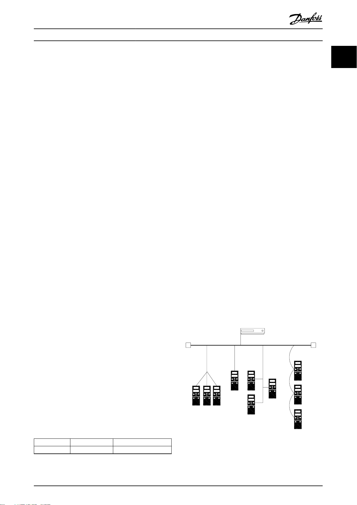
24 V
Trunk line
Power supply
Drop lines 1
RT=Termination resistors
R
T
R
T
195NA228.10
1 1 1
1
Introduction Programming Guide
1 Introduction
1.1 Purpose of the Manual
The VLT® DeviceNet MCA 104 Programming Guide provides
information about conguring the system, controlling the
frequency converter, parameter access, programming,
troubleshooting, and some typical application examples.
The programming guide is intended for use by qualied
personnel who are familiar with the VLT® frequency
converter, with DeviceNet technology, and with the PC or
PLC that is used as a master in the system.
Read the instructions before programming and follow the
procedures in this manual.
VLT® is a registered trademark.
1.2 Additional Resources
Resources available for the VLT® frequency converter and
optional equipment:
The VLT® Operating Instructions provide the
•
necessary information for getting the VLT
frequency converter up and running.
The VLT® Design Guide provides detailed
•
information about capabilities and functionality
to design motor control systems.
The VLT® Programming Guide provides greater
•
detail on working with parameters and many
application examples.
The VLT® DeviceNet MCA 104 Installation Guide
•
provides information about installing the
DeviceNet and troubleshooting.
The VLT® DeviceNet MCA 104 Programming Guide
•
provides information about conguring the
system, controlling the VLT® frequency converter,
parameter access, programming, troubleshooting,
and some typical application examples.
Supplementary publications and manuals are available
from Danfoss. See vlt-drives.danfoss.com/Support/Technical-
Documentation/ for listings.
®
Product Overview
1.4
This programming guide relates to the DeviceNet interface.
Ordering number:
130B1102 (non-coated version).
•
130B1210 (conformal coated version).
•
DeviceNet is a low-level network that standardizes
communications between industrial devices (sensors, limit
switches, motor controls) and high-level devices
(controllers). DeviceNet follows the Open Systems Interconnection (OSI) model and is based on CAN technology for
media access control and physical signaling.
DeviceNet systems can be congured to operate in a
master/slave or a distributed control architecture using
peer-to-peer communication. Up to 63 nodes in a multidrop network topology are supported. By using the same
cable for communication, communication options can be
powered directly from the bus. Nodes can be removed or
inserted without powering down the network.
Each node on the network has its own unique media
access control identier (MAC ID) to distinguish it on the
network. The access control is based on the CSMA/CA
(carrier sense multiple access/collision avoidance) principle,
meaning that all nodes may have access to the network at
the same time. When 2 nodes attempt to get control of
the network bus simultaneously, the CAN protocol resolves
the issue by arbitration. In this way, collisions on the
network are avoided.
DeviceNet denes device proles for devices belonging to
specic classes. For other devices, dene a custom class to
make it DeviceNet compatible. All the above enhances the
interchangeability and interoperability of the network.
1 1
1.3
This manual is regularly reviewed and updated. All
suggestions for improvement are welcome. Table 1.1 shows
the document version and the corresponding software
version.
Table 1.1 Document and Software Version
MG92F102 Danfoss A/S © 12/2015 All rights reserved. 3
Document and Software Version
Edition Remarks Software version
MG92F1xx First edition. 4.4x
Illustration 1.1 Topology
Introduction
VLT® DeviceNet MCA 104
11
VLT® DeviceNet MCA 104 is designed to communicate with
any master abiding by the DeviceNet standard. It is
intended for use with:
VLT® HVAC Drive FC 102
•
VLT® AQUA Drive FC 202
•
VLT® AutomationDrive FC 301/FC 302
•
1.5 Approvals and Certications
More approvals and certications are available. For more
information, contact a local Danfoss partner.
1.6 Symbols, Abbreviations and
Conventions
Abbreviation Denition
ACK ACKnowledge
BOC Bus o counter
BOOL Boolean expression
CAN Controller area network
CSMA/CA Carrier sense multiple access/collision avoidance
COS Change of state
CTW Control word
EDS Electronic data sheet
EMC Electromagnetic compatibility
ETR Electronic thermal relay
FIFO First in rst out
HF High frequency
HPFB High performance eldbus
I/O Input/output
ISO International standards organization
LCD Liquid crystal display
LED Light emitting diode
LSB Least signicant bit
MAC ID Media access control identier
MAV Main actual value
MRV Main reference value
MSB Most signicant bit
N/A Not applicable
ODVA Open DeviceNet Vendor Association
OSI Open systems interconnection
PC Personal computer
PCD Process data
PIW Peripheral input word
PLC Programmable logic control
PNU Parameter number
PPO Parameter-process data object
QW Peripheral output word
Abbreviation Denition
SINT Signed integer
STW Status word
VSD Variable speed drive
UDINT Unsigned double integer
UNIT Unsigned integer
USINT Unsigned short integer
Table 1.2 Symbols and Abbreviations
Conventions
Numbered lists indicate procedures.
Bullet lists indicate other information.
Italicized text indicates:
Cross reference.
•
Link.
•
Parameter name.
•
Parameter group name.
•
Parameter option.
•
Footnote.
•
4 Danfoss A/S © 12/2015 All rights reserved. MG92F102
Safety Programming Guide
2 Safety
2.1 Safety Symbols
The following symbols are used in this manual:
WARNING
Indicates a potentially hazardous situation that could
result in death or serious injury.
CAUTION
Indicates a potentially hazardous situation that could
result in minor or moderate injury. It can also be used to
alert against unsafe practices.
NOTICE
Indicates important information, including situations that
can result in damage to equipment or property.
2.2 Qualied Personnel
Correct and reliable transport, storage, installation,
operation, and maintenance are required for the troublefree and safe operation of the frequency converter. Only
qualied personnel are allowed to install and operate this
equipment.
Qualied personnel are dened as trained sta, who are
authorized to install, commission, and maintain equipment,
systems, and circuits in accordance with pertinent laws and
regulations. Additionally, the qualied personnel must be
familiar with the instructions and safety measures
described in these operating instructions.
Safety Precautions
2.3
WARNING
HIGH VOLTAGE
Frequency converters contain high voltage when
connected to AC mains input, DC supply, or load sharing.
Failure to perform installation, start-up, and maintenance
by qualied personnel can result in death or serious
injury.
Only qualied personnel must perform instal-
•
lation, start-up, and maintenance.
WARNING
UNINTENDED START
When the frequency converter is connected to AC mains,
DC supply, or load sharing, the motor may start at any
time. Unintended start during programming, service, or
repair work can result in death, serious injury, or
property damage. The motor can start with an external
switch, a eldbus command, an input reference signal
from the LCP or LOP, via remote operation using MCT 10
Set-up Software, or after a cleared fault condition.
To prevent unintended motor start:
Press [O/Reset] on the LCP before
•
programming parameters.
Disconnect the frequency converter from the
•
mains.
Completely wire and assemble the frequency
•
converter, motor, and any driven equipment
before connecting the frequency converter to
AC mains, DC supply, or load sharing.
WARNING
DISCHARGE TIME
The frequency converter contains DC-link capacitors that
can remain charged even when the frequency converter
is not powered. Failure to wait the specied time after
power has been removed before performing service or
repair work can result in death or serious injury.
Stop the motor.
•
Disconnect the AC mains and remote DC-link
•
supplies, including battery back-ups, UPS, and
DC-link connections to other frequency
converters.
Disconnect or lock the PM motor.
•
Wait for the capacitors to discharge fully before
•
performing any service or repair work. The
waiting time is specied in the relevant
frequency converter operating instructions,
Chapter 2 Safety.
WARNING
LEAKAGE CURRENT HAZARD
Leakage currents exceed 3.5 mA. Failure to ground the
frequency converter properly can result in death or
serious injury.
Ensure the correct grounding of the equipment
•
by a certied electrical installer.
2 2
MG92F102 Danfoss A/S © 12/2015 All rights reserved. 5

Safety
VLT® DeviceNet MCA 104
WARNING
EQUIPMENT HAZARD
22
Contact with rotating shafts and electrical equipment
can result in death or serious injury.
Ensure that only trained and qualied personnel
•
perform installation, start-up, and maintenance.
Ensure that electrical work conforms to national
•
and local electrical codes.
Follow the procedures in this guide.
•
CAUTION
INTERNAL FAILURE HAZARD
An internal failure in the frequency converter can result
in serious injury when the frequency converter is not
properly closed.
Ensure that all safety covers are in place and
•
securely fastened before applying power.
6 Danfoss A/S © 12/2015 All rights reserved. MG92F102
Conguration Programming Guide
3 Conguration
3.1 Congure the DeviceNet Network
All DeviceNet stations that are connected to the same bus
network must have a unique station address. Select the
DeviceNet address of the frequency converter via:
Address switches (default 63).
•
Parameter 10-02 MAC ID (default 63).
•
Class code 0X03, instance 1, attribute 1.
•
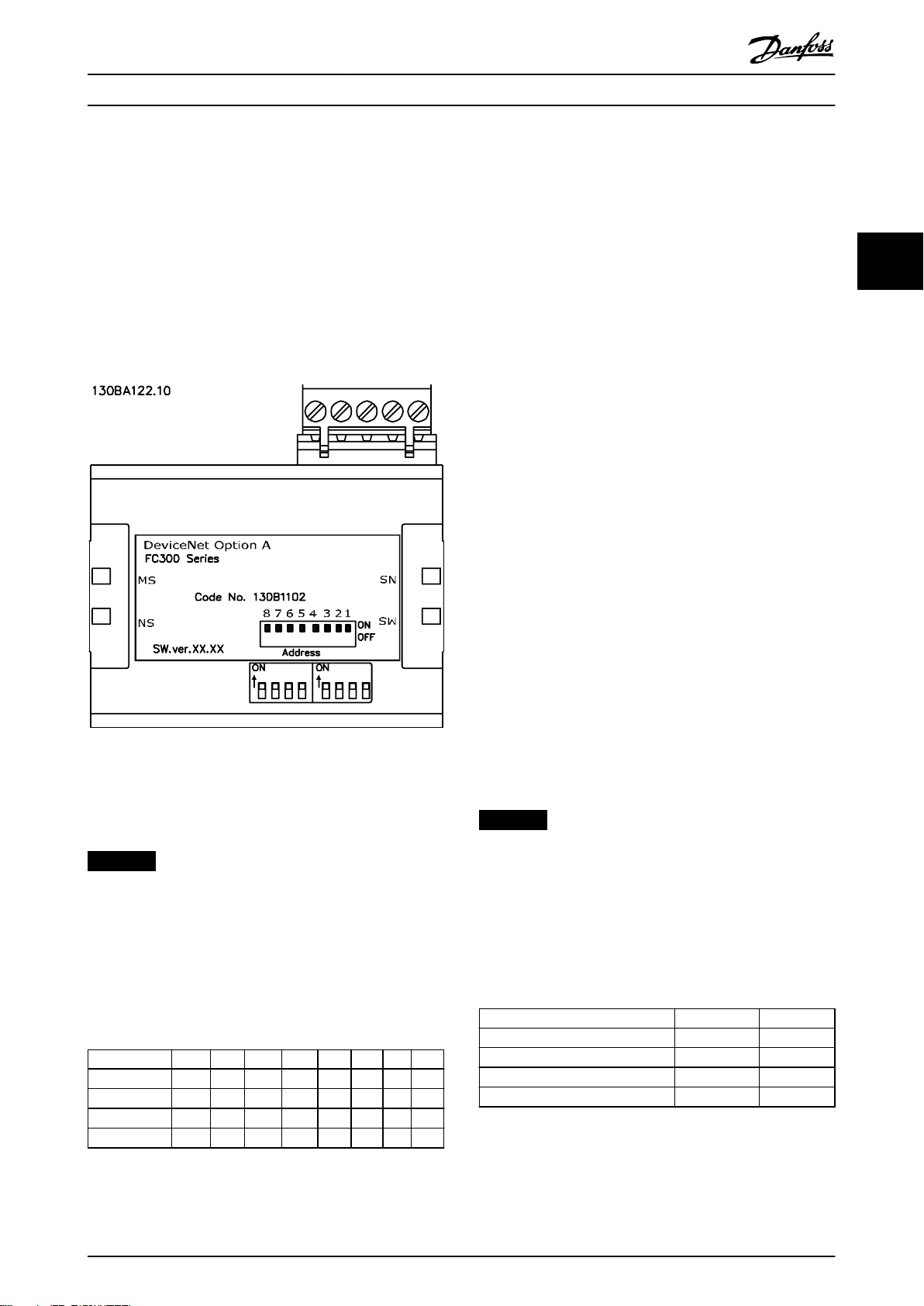
Illustration 3.1 VLT
®
DeviceNet MCA 104 Interface
3.1.1 Setting the DeviceNet Address using
the Address Switches
NOTICE
Switch o the power supply before changing the address
switches. The address change comes into eect at the
next power-up, and can be read in parameter 10-02 MAC
ID.
Set the address switches to give the option a unique ID.
Select an address range from 0–63 (factory setting 63)
according to Table 3.1.
Switch 8 7 6 5 4 3 2 1
Address value – – +32 +16 +8 +4 +2 +1
5 – – OFF OFF OFF ON OFF ON
20 – – OFF ON OFF ON OFF OFF
35 – – ON OFF OFF OFF ON ON
3.1.2 Setting the DeviceNet Address via
Parameter 10-02 MAC ID
Set the address via parameter 10-02 MAC ID if the hardware
switches are set to 63 (factory setting). The address change
comes into eect at the next power-up.
3.1.3 Setting the DeviceNet Address with
the Object Class Code 0x03, Instance
1, Attribute 1
Set the address via the DeviceNet object class code 0x03
attribute 1 command when the address switch is set to 63
(factory setting). A new address becomes eective
immediately after the class code 0x03, instance 1, attribute
1 command.
3.1.4 Setting the Baud Rate
All DeviceNet stations connected to the same bus network
must have the same baud rate. Select the baud rate of the
frequency converter via:
Address switches.
•
Parameter 10-01 Baud Rate Select (default 125
•
kBd).
Object class code 0x03, instance 1, attribute 2.
•
3.1.5 Setting the DeviceNet Baud Rate
using the Address Switches
NOTICE
Switch o the power supply before changing the address
switches. The baud rate change comes into eect at the
next power-up, and can be read in parameter 10-01 Baud
Rate Select.
Use the address switches to select a baud rate of 125 k
baud (factory setting), 250 k baud, or 500 k baud, see
Table 3.2:
Baud rate switch 8 7
Parameter 10-01 Baud Rate Select 1 1
125 kBd 0 0
250 kBd 0 1
500 kBd 1 0
Table 3.2 Address Switches
3 3
Table 3.1 Settings for the Address Switches
MG92F102 Danfoss A/S © 12/2015 All rights reserved. 7

Conguration
VLT® DeviceNet MCA 104
3.1.6 Setting the DeviceNet Baud Rate via
3.3 Congure the Frequency Converter
Parameter 10-01 Baud Rate Select
3.3.1 Frequency Converter Parameters
Set the baud rate via parameter 10-01 Baud Rate Select if
the address switches 1 and 2 are set to ON (factory
33
setting). The baud rate change comes into eect at the
next power-up.
3.1.7 Setting the DeviceNet Baud Rate with
the Object Class Code 0x03, Attribute
2
Set the baud rate via the DeviceNet object class code 0x03
attribute 2 command, when the address switches 1 and 2
are set to ON (factory setting). A new baud rate becomes
eective immediately after the class code 0x03 attribute 2
command.
3.2 Congure the Master
3.2.1 EDS File
A large part area of the system conguration is the setting
of application-related parameters. EDS (Electronic Data
Sheet) les simplify the setting up of most of the
DeviceNet congurable parameters. For o-line congu-
ration, Danfoss provides a generic English EDS le covering
all voltage and power sizes. Download the EDS le from
www.danfoss.com/drives.
NOTICE
The EDS le does not contain all parameters. It contains
only a selected, limited number of parameters with
generic minimum, maximum, and default values.
Note the following parameters when conguring the
frequency converter with a DeviceNet interface. Refer to
chapter 6 Parameters for more details of each parameter.
Parameter 0-40 [Hand on] Key on LCP.
•
If the Hand key on the frequency converter is
activated, control of the frequency converter via
the DeviceNet interface is disabled. After initial
power-up the frequency converter automatically
detects whether a eldbus option is installed in
slot A, and sets parameter 8-02 Control Word
Source to [3] Option A. If an option is added to,
changed in, or removed from an already commissioned frequency converter, it does not change
parameter 8-02 Control Word Source but enters trip
mode, and the frequency converter shows an
error.
Parameter 8-10 Control Word Prole (see
•
chapter 4 Control). Select between the Danfoss FC
Prole and the ODVA prole. Select the desired
DeviceNet instance in parameter 10-10 Process
Data Type Selection.
Parameter 8-50 Coasting Select to
•
parameter 8-56 Preset Reference Select (see
chapter 6 Parameters). Selection of how to gate
the DeviceNet control commands with digital
input command of the control card.
NOTICE
When parameter 8-01 Control Site is set to [2] Control
word only, the settings in parameter 8-50 Coasting Select
to parameter 8-56 Preset Reference Select is overruled,
and all act on bus control.
Parameter 8-03 Control Word Timeout Time to
•
parameter 8-05 End-of-Timeout Function. The
reaction in the event of a bus timeout is set via
these parameters.
Parameter 10-10 Process Data Type Selection.
•
Default is 125 kbps.
Parameter 10-02 MAC ID. Default is 63.
•
8 Danfoss A/S © 12/2015 All rights reserved. MG92F102
Control Programming Guide
4 Control
4.1 DeviceNet Process Control Modes
This section describes 2 of 3 possible process control
modes:
Polling.
•
Change of state (COS).
•
The 3rd FC control mode uses the acyclic mode explicit
messaging via the standard DeviceNet control supervisory
object class 29H. The control supervisory object is
described in chapter 5.3 DeviceNet Object Classes.
4.1.1 Polling
Table 4.1 is a classic master/slave connection and the
standard DeviceNet operating mode. The master controls
the data exchange by sending cyclic poll-requests to the
connected slave, and the slave answers by sending a pollresponse to the master. The master can control and
monitor the frequency converter by polling the DeviceNet
or Danfoss objects (I/O instances).
Master
Slave
Table 4.1 Standard DeviceNet Operation Mode - Polled I/O
Slave
⇒
Master
⇒
CTW MRV
STW MAV
4.1.2 Change of State, COS
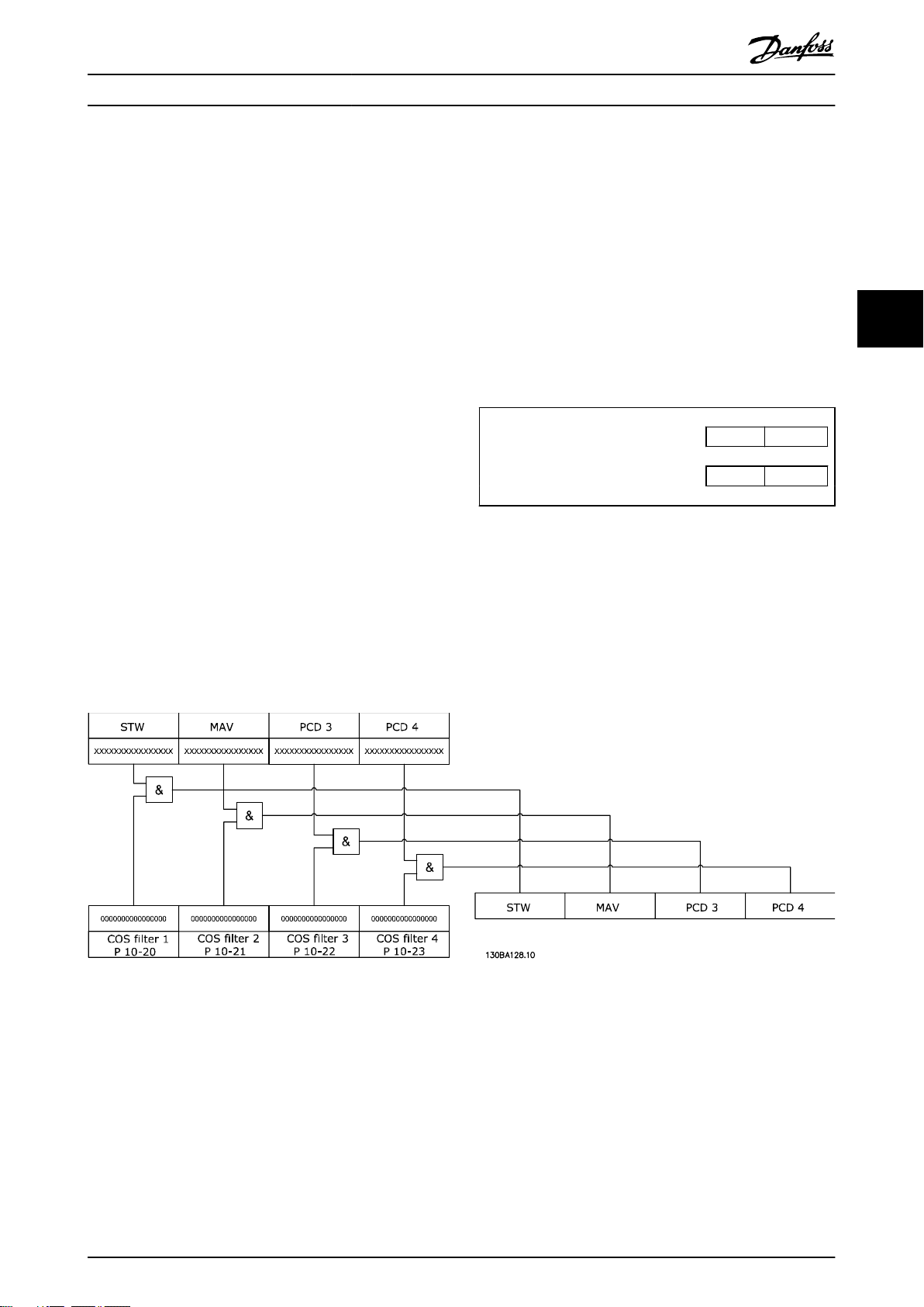
COS is an event-controlled operating mode used to minimize network trac. Messages are transmitted only if a dened
state or value has changed. The condition for triggering a COS message is determined by the insertion of COS-lters
(parameter 10-20 COS Filter 1 to parameter 10-23 COS Filter 4), for each bit in the dierent PCD words. The lter acts like a
logical AND function: If a bit in the lter is set to 1, the COS function triggers after a change to the corresponding bit for
the PCD word.
4 4
Illustration 4.1 Dierent PCDs and the Corresponding Filter Parameters
Parameter 10-20 COS Filter 1 to parameter 10-23 COS Filter 4 can be used to lter out undesired events for COS. If a lter bit is
set to 0, the corresponding I/O instance bit is unable to produce a COS message. By default, all bits in the COS lters are set
to 0.
To signal that the connection has not been interrupted, or the device is not powered o, a heartbeat message is
transmitted within a specied time interval (heartbeat interval). This interval is dened in attribute heartbeat time of the
connection object, class code 0x05.
To prevent the device from producing heavy network trac if a value changes frequently, the production inhibit time (an
attribute of the connection object) is dened. This parameter denes the minimum time between 2 COS messages.
MG92F102 Danfoss A/S © 12/2015 All rights reserved. 9
Control
The attribute expected package rate denes the maximum time between 2 COS messages even when the value is
unchanged. In the event of COS connection, the explicit package rate is identical with the heartbeat interval mentioned
above. This timer is used both as transmission trigger and inactivity watchdog, depending on whether the connection is
producer or consumer.
VLT® DeviceNet MCA 104
4.2 I/O Assembly Instances
I/O assembly instances are several
information. Illustration 4.2 shows the I/O assembly instance options for controlling and monitoring the frequency converter.
dened process control objects with dened content comprising control and status
44
Illustration 4.2 I/O Assembly Instance Options
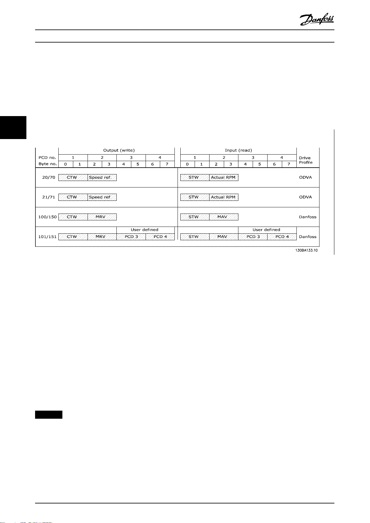
4.3 Process Data
Process data comprises the control and status data in the I/O assembly instances.
The CTW, MRV, STW, and MAV have
4 are freely congurable, for instance 101/151 via parameter 10-11 Process Data Cong Write and parameter 10-12 Process
Data Cong Read.
All PCDs are freely congurable for instance 102/152.
DeviceNet provides a exible way to customize the number of process data (I/O words) and the functionality of each word.
To activate the user denable process data, select the I/O instance 101/151 in parameter 10-10 Process Data Type Selection.
This changes the I/O size to 4 words in the input and output area. This selection uses the Danfoss-specic prole for the
control word and status word as well as for the main reference value/main actual value.
The rst 2 words are xed on the DeviceNet, whereas PCD 3 and PCD 4 are user congurable. The number of PCDs active in
a system is xed to 2 words.
dened formats and functions, depending on the I/O instance selected. PCD 3 and PCD
NOTICE
To select [1] Instance 101/151 in parameter 10-10 Process Data Type Selection, set parameter 8-10 Control Word Prole to
[0] FC prole.
To enable use of PCD data from the DeviceNet, congure the contents of each single PCD word in parameter 10-11 Process
Data Cong Write and parameter 10-12 Process Data Cong Read. Changes to parameter 10-11 Process Data Cong Write and
parameter 10-12 Process Data Cong Read are eected immediately in the PCD data.
10 Danfoss A/S © 12/2015 All rights reserved. MG92F102
CTW
REF
CTW
REF
PCD 2
write
PCD 3
write
STW MAV
STW MAV
PCD 2
read
PCD 3
read
Instance
100
101
150
151
Originator (PLC) --> Target (Drive)
Fixed contents User dened contents
Instance
STW MAV
70
STW MAV
71
CTW
REF
20
CTW
REF
21
Byte #
Byte #
Word #
Word #
Target (Drive) --> Originator (PLC)
1 2 3 4 5 6 7 8 1 2 3 4 5 6 7 8
1 2 3 4 1 2 3 4
130BE709.10
Control Programming Guide
Illustration 4.3 Process Data
4 4
4.4 ODVA Control Prole
4.4.1 Control Word under Instances 20/70
and 21/71
Set parameter 8-10 Control Word Prole to ODVA and select
the instance in parameter 10-10 Process Data Type Selection.
Illustration 4.4 The Control Word in Instances 20 and 21
NOTICE
The bits 00 and 02 in instance 20 are identical with bits
00 and 02 in the more extensive instance 21.
Bit Instance 20 Instance 21
Bit = 0 Bit = 1 Bit = 0 Bit = 1
00 Stop Run Fwd Stop Run Fwd
01 – – Stop Run Rev
02 No function Fault reset No function Fault reset
03 – – – –
04 – – – –
05 – – – Net Ctrl
06 – – – Net Ref
07–15 – – – –
Explanation of the bits:
Bit 0, Run Fwd
Bit 0 = 0: The frequency converter has a stop command.
Bit 0 = 1: Leads to a start command, and the frequency
converter runs the motor clockwise.
Bit 1, Run Rev
Bit 1 = 0: Leads to a stop of the motor.
Bit 1 = 1: Leads to a start reverse of the motor, and the
frequency converter runs the motor counterclockwise.
Bit 2, Fault Reset
Bit 2 = 0: There is no reset of a trip.
Bit 2 = 1: A trip is reset.
Bit 3, No function
Bit 3: No function.
Bit 4, No function
Bit 4: No function.
Bit 5, Net Control
Bit 5 = 0: The frequency converter is controlled via the
standard inputs.
Bit 5 = 1: The DeviceNet controls the frequency converter.
NOTICE
Changes aect parameter 8-50 Coasting Select to
parameter 8-56 Preset Reference Select.
Bit 6, Net Reference
Bit 6 = 0: Reference is from the standard inputs.
Bit 6 = 1: Reference is from DeviceNet.
Table 4.2 Bits in Instances 20 and 21
MG92F102 Danfoss A/S © 12/2015 All rights reserved. 11
Control
VLT® DeviceNet MCA 104
NOTICE
Changes aect parameter 3-15 Reference Resource 1 to
parameter 3-17 Reference Resource 3.
For the speed reference, see chapter 4.4.3 Bus Speed
Reference Value under Instances 20/70 and 21/71.
4.4.2 Status Word under Instances 20/70
44
and 21/71
Illustration 4.5 Status Word in Instances 70 and 71
NOTICE
The bits 00 and 02 in instance 70 are identical with bits
00 and 02 in the more extensive instance 71.
Bit Instance 70 Instance 71
Bit = 0 Bit = 1 Bit = 0 Bit = 1
00 – Fault – Fault
01 – – – Warning
02 – Running 1
Fwd
03 – – – Running 2
04 – – – Ready
05 – – – Control
06 – – – Reference
07 – – – At
08–15 – – State attribute
– Running 1
Fwd
Rev.
from Net
from Net
reference
Bit 3, Running 2
Bit 3 = 0: The frequency converter is not in the running
reverse state, or run 2 is not set.
Bit 3 = 1: The frequency converter state attribute is
enabled or stopping, or fault-stop and bit 0 (run 2) of the
control word are set at the same time.
Bit 4, Ready
Bit 4 = 0: The state attribute is in another state.
Bit 4 = 1: The state attribute is ready, enabled, or stopping.
Bit 5, Control from net
Bit 5 = 0: The frequency converter is controlled from the
standard inputs.
Bit 5 = 1: The DeviceNet has control (start, stop, reverse) of
the frequency converter.
Bit 6, Ref from net
Bit 6 = 0: The reference comes from inputs to the
frequency converter.
Bit 6 = 1: The reference comes from the DeviceNet.
Bit 7, At reference
Bit 7 = 0: The motor is running, but the present speed is
dierent from the preset speed reference, for example, the
speed is being ramped up/down during start/stop.
Bit 7 = 1: The frequency converter and reference speeds
are equal.
Bit 8–15, State attribute
(Instance 71 only)
Represents the state attribute of the frequency converter,
as indicated in Table 4.4.
Bit number Meaning
8 (Vendor specic)
9 Start up
10 Not ready
11 Ready
12 Enabled
13 Stopping
14 Fault stop
15 Faulted
Table 4.3 Bits in Instances 70 and 71
Explanation of the bits:
Bit 0, Fault
Bit 0 = 0: There is no fault in the frequency converter.
Bit 0 = 1: There is a fault in the frequency converter.
Bit 1, Warning
Bit 0 = 0: There is no unusual situation.
Bit 0 = 1: An abnormal condition has arisen.
Bit 2, Running 1
Bit 2 = 0: The frequency converter is not in the running
forward state, or run 1 is not set.
Bit 2 = 1: The frequency converter state attribute is
enabled or stopping, or that fault-stop and bit 0 (run 1) of
the control word are set at the same time.
12 Danfoss A/S © 12/2015 All rights reserved. MG92F102
Table 4.4 State Attribute (Instance 71)
For more details of the actual output speed, see
chapter 4.4.4 Actual Output Speed under Instances 20/70 and
21/71.
4.4.3 Bus Speed Reference Value under
Instances 20/70 and 21/71
The speed reference value is transmitted to the frequency
converter as a 16-bit word. The value is transmitted as a
whole number. Negative gures are formatted by 2’s
complement.
Control Programming Guide
Illustration 4.6 Speed Reference Value
The bus speed reference has the following format:
Parameter 3-00 Reference Range = 0 [ref
MIN
to ref
MAX
] 0
(0000 hex) [RPM] to + 32767 (7FFF hex) [RPM]
Parameter 3-00 Reference Range = 1 [-ref
MAX
to +ref
MAX
]
-32767 (8001 hex ) to +32767 [RPM] (7FFF hex)
The actual reference [Ref. %] in the frequency converter
depends on the settings in the following parameters:
Parameter 1-23 Motor Frequency
Parameter 1-25 Motor Nominal Speed
Parameter 3-03 Maximum Reference
NOTICE
When the bus speed reference is negative, and the
control word contains a run reverse signal, the frequency
converter runs clockwise (- - is +).
Example:
Parameter 1-25 Motor Nominal Speed = 1420 RPM
Parameter 1-23 Motor Frequency = 50 Hz
Parameter 3-03 Maximum Reference = 1420 RPM
To run the motor at 25%, the reference transmitted must
be: (1420x0.25) = 355 = 16.3 hex
163 hex ⇒ 25% ⇒ F
4.4.4 Actual Output Speed under Instances
20/70 and 21/71
= 12.5 Hz
out
FC Control Prole
4.5
4.5.1 Control Word under Instances
100/150, 101/151, and 102/152
To select FC protocol in the control word, set
parameter 8-10 Control Word Prole to [0] FC prole. The
control word is used to send commands from a master
(PLC or PC) to a slave (frequency converter).
Illustration 4.8 Control Words in Instances 100, 101, and 102
Bit Bit value = 0 Bit value = 1
00 Reference value External selection lsb
01 Reference value External selection msb
02 DC brake Ramp
03 Coasting No coasting
04 Quick stop Ramp
05 Hold output frequency Use ramp
06 Ramp stop Start
07 No function Reset
08 No function Jog
09 Ramp 1 Ramp 2
10 Data invalid Data valid
11 No function Relay 01 active
12 No function Relay 04 active
13 Parameter set-up Selection lsb
14 Parameter set-up Selection msb
15 No function Reverse
4 4
Table 4.5 Bits in Instances 100, 101, and 102
Explanation of the control bits:
Bits 00/01
Bits 00 and 01: Select between the 4 reference values,
Illustration 4.7 Actual Output Speed Value
which are pre-programmed in parameter 3-10 Preset
Reference according to Table 4.6.
The value of the actual speed of the motor, is transmitted
in the form of a 16-bit word.
The value is transmitted as a whole number (negative
gures are formed with 2's complement).
-32767 (8000 hex) [RPM] to +32767 [RPM] (7FFF hex) [RPM]
MG92F102 Danfoss A/S © 12/2015 All rights reserved. 13
Programmed
reference
value
1 3-10 [0] 0 0
2 3-10 [1] 0 1
3 3-10 [2] 1 0
4 3-10 [3] 1 1
Table 4.6 Reference Values
Parameter Bit 01 Bit 00

Control
VLT® DeviceNet MCA 104
NOTICE
In parameter 8-56 Preset Reference Select, a selection is
made to dene how bit 00/01 gates with the
corresponding function on the digital inputs.
Bit 02, DC brake
Bit 02 = 0: Leads to DC braking and stop. Braking current
and duration are set in parameter 2-01 DC Brake Current
44
and parameter 2-02 DC Braking Time.
Bit 02 = 1: Leads to ramping.
Bit 03, Coasting
Bit 03 = 0: Causes the frequency converter to immediately
release the motor (the output transistors are disabled), and
coasts to a standstill.
Bit 03 = 1: Enables the frequency converter to start the
motor if the other starting conditions are fullled.
NOTICE
In parameter 8-50 Coasting Select, a selection is made to
dene how bit 03 gates with the corresponding function
on a digital input.
Bit 04, Quick stop
Bit 04 = 0: Causes a stop, in which the motor speed is
ramped down to stop via parameter 3-81 Quick Stop Ramp
Time.
Bit 05, Hold output frequency
Bit 05 = 0: Causes the present output frequency (in Hz) to
freeze. The frozen output frequency can then be changed
only with the digital inputs (parameter 5-10 Terminal 18
Digital Input to parameter 5-15 Terminal 33 Digital Input)
programmed to speed up and speed down.
NOTICE
If hold output is active, only the following can stop the
frequency converter:
Bit 03 coasting stop.
•
Bit 02 DC braking.
•
Digital input (parameter 5-10 Terminal 18 Digital
•
Input to parameter 5-15 Terminal 33 Digital
Input) programmed to DC braking, coasting
stop, or reset and coasting stop.
Bit 06, Ramp stop/start
Bit 06 = 0: Causes a stop, in which the motor speed is
ramped down to stop via the selected ramp down
parameter.
Bit 06 = 1: Allows the frequency converter to start the
motor, if the other starting conditions are fullled.
NOTICE
In parameter 8-53 Start Select, a selection is made to
dene how bit 06 ramp stop/start gates with the
corresponding function on a digital input.
Bit 07, Reset
Bit 07 = 0: Does not cause a reset.
Bit 07 = 1: Resets a trip. Reset is activated on the leading
edge of the signal, that is, when changing from logic 0 to
logic 1.
Bit 08, Jog
Bit 08 = 1: The frequency converter ramps up/ramps down
according to the setting in parameter 3-19 Jog Speed [RPM].
Bit 09, Selection of ramp 1/2
Bit 09 = 0: Ramp 1 is active (parameter 3-40 Ramp 1 Type to
parameter 3-47 Ramp 1 S-ramp Ratio at Decel. Start).
Bit 09 = 1: Ramp 2 is active (parameter 3-50 Ramp 2 Type to
parameter 3-57 Ramp 2 S-ramp Ratio at Decel. Start).
Bit 10, Data not valid/Data valid
Tells the frequency converter whether to use or to ignore
the control word.
Bit 10 = 0: Ignores the control word.
Bit 10 = 1: Uses the control word to be used. This function
is relevant, because the control word is always contained
in the telegram, regardless of the type of telegram. It is
possible to turn o the control word if you do not wish to
use it with updating or reading parameters.
Bit 11, Relay 01
Bit 11 = 0: Relay not activated.
Bit 11 = 1: Relay 01 activated, provided [36] control word
bit 11 is selected in parameter 5-40 Function Relay.
Bit 12, Relay 04
Bit 12 = 0: Relay 04 is not activated.
Bit 12 = 1: Relay 04 is activated, provided [37] control word
bit 12 is selected in parameter 5-40 Function Relay.
Bit 13/14, Selection of set-up
Bits 13 and 14 are used to select from the 4 menu set-ups
according to Table 4.7.
Set-up Bit 14 Bit 13
1 0 0
2 0 1
3 1 0
4 1 1
Table 4.7 Menu Set-up
The function is only possible when [9] Multi Set-up is
selected in parameter 0-10 Active Set-up.
NOTICE
In parameter 8-55 Set-up Select, a selection is made to
dene how bits 13/14 gate with the corresponding
function on the digital inputs.
Bit 15 Reverse
Bit 15 = 0: No reversing.
Bit 15 = 1: Reversing.
14 Danfoss A/S © 12/2015 All rights reserved. MG92F102

Control Programming Guide
4.5.2 Status Word under Instances 100/150,
101/151, and 102/152
Illustration 4.9 Status Words in Instances 150/151/152
Bit Bit = 0 Bit = 1
00 Control not ready Control ready
01 Drive not ready Drive ready
02 Coasting Enable
03 No error Trip
04 No error Error (no trip)
05 Reserved –
06 No error Trip lock
07 No warning Warning
08 Speed reference Speed = reference
09 Local operation Bus control
10 Out of frequency limit Frequency limit ok
11 No operation In operation
12 Drive ok Stopped, auto start
13 Voltage ok Voltage exceeded
14 Torque ok Torque exceeded
15 Timer ok Timer exceeded
Table 4.8 Status Bits
Explanation of the status bits:
Bit 00, Control not ready/ready
Bit 00 = 0: The frequency converter has tripped.
Bit 00 = 1: The frequency converter controls are ready, but
the power component is not necessarily receiving any
power supply (if there is 24 V external supply to controls).
Bit 01, Drive ready
Bit 01 = 1: The frequency converter is ready for operation.
Bit 02, Coasting stop
Bit 02 = 0: The frequency converter has released the motor.
Bit 02 = 1: The frequency converter can start the motor
when a start command is given.
Bit 03, No error/trip
Bit 03 = 0: The frequency converter is not in fault mode.
Bit 03 = 1: The frequency converter is tripped, and a reset
signal is required to re-establish operation.
Bit 04, No error/error (no trip)
Bit 04 = 0: The frequency converter is not in fault mode.
Bit 04 = 1: There is a frequency converter error but no trip.
Bit 05, Not used
Bit 05: Not used in the status word.
Bit 06, No error/trip lock
Bit 06 = 0: The frequency converter is not in fault mode.
Bit 06 = 1: The frequency converter is tripped and locked.
Bit 07, No warning/warning
Bit 07 = 0: There are no warnings.
Bit 07 = 1: A warning has occurred.
Bit 08, Speed reference/speed = reference
Bit 08 = 0: The motor is running, but the present speed is
dierent from the preset speed reference. For example, it
could be the case while the speed is being ramped up/
down during start/stop.
Bit 08 = 1: The present motor speed matches the preset
speed reference.
Bit 09, Local operation/bus control
Bit 09 = 0: [STOP/RESET] is activated on the control unit, or
[2] Local in parameter 3-13 Reference Site is selected. It is
not possible to control the frequency converter via serial
communication.
Bit 09 = 1: It is possible to control the frequency converter
via the eldbus/serial communication.
Bit 10, Out of frequency limit
Bit 10 = 0: The output frequency has reached the value in
parameter 4-52 Warning Speed Low or
parameter 4-53 Warning Speed High.
Bit 10 = 1: The output frequency is within the dened
limits.
Bit 11, No operation/in operation
Bit 11 = 0: The motor does not run.
Bit 11 = 1: The frequency converter has a start signal, or
the output frequency is greater than 0 Hz.
Bit 12, Drive OK/stopped, auto start
Bit 12 = 0: There is no temporary overtemperature on the
inverter.
Bit 12 = 1: The inverter has stopped because of overtemperature, but the unit has not tripped and resumes
operation once the overtemperature stops.
Bit 13, Voltage OK/limit exceeded
Bit 13 = 0: There are no voltage warnings.
Bit 13 = 1: The DC voltage in the frequency converters DC
link is too low or too high.
Bit 14, Torque OK/limit exceeded
Bit 14 = 0: The motor current is lower than the torque limit
selected in parameter 4-16 Torque Limit Motor Mode or
parameter 4-17 Torque Limit Generator Mode.
Bit 14 = 1: The torque limits in parameter 4-16 Torque Limit
Motor Mode and parameter 4-17 Torque Limit Generator
Mode are exceeded.
Bit 15, Timer OK/limit exceeded
Bit 15 = 0: The timers for motor thermal protection and
frequency converter thermal protection, respectively, have
not exceeded 100%.
Bit 15 = 1: One of the timers has exceeded 100%.
4 4
MG92F102 Danfoss A/S © 12/2015 All rights reserved. 15

Control
VLT® DeviceNet MCA 104
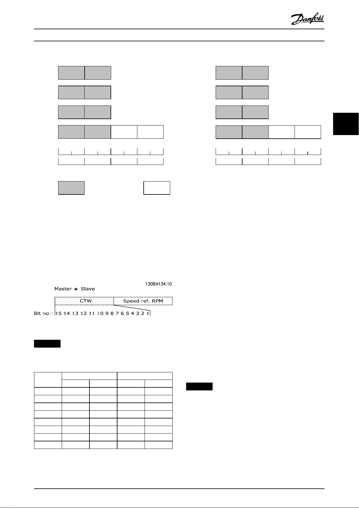
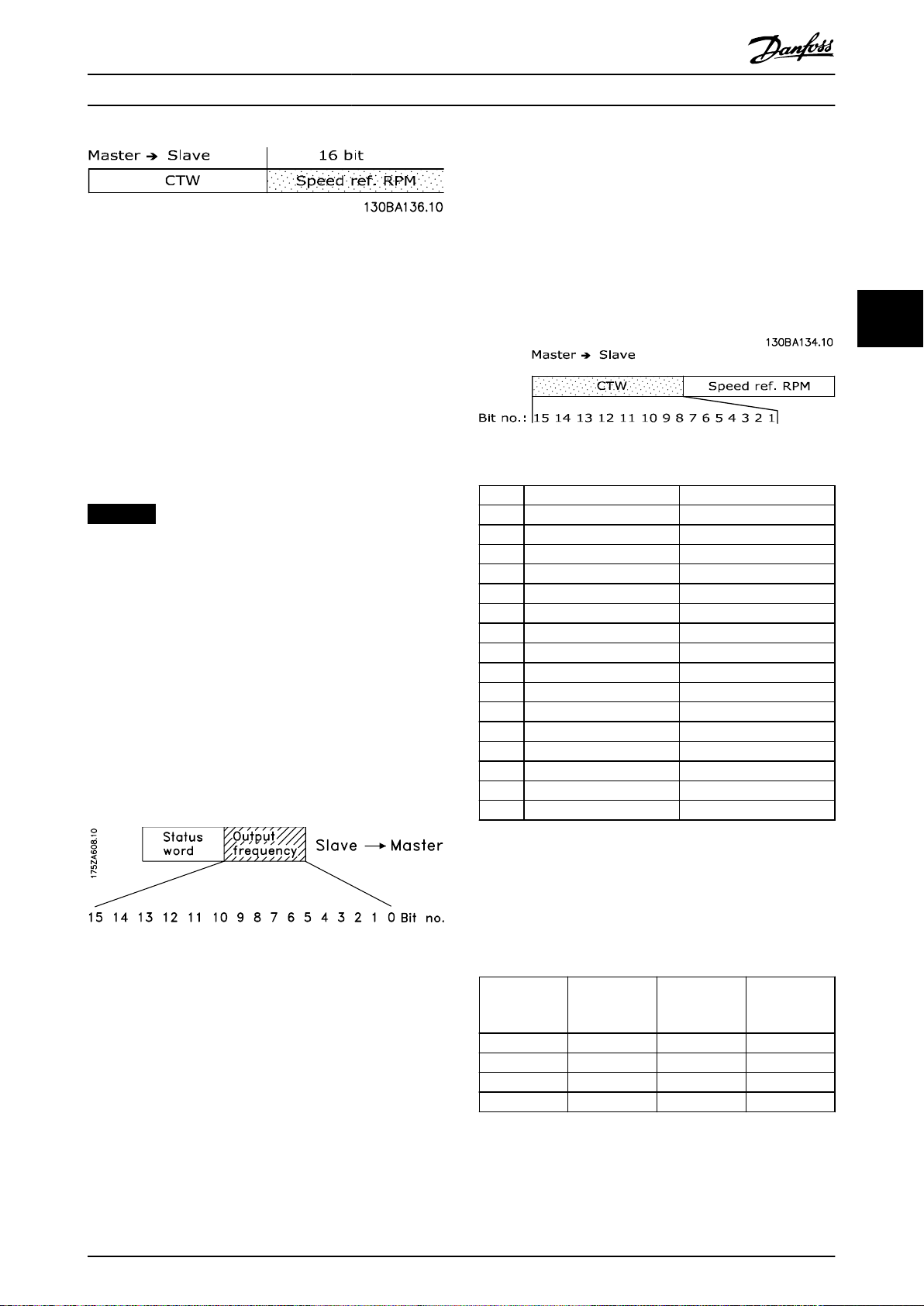
4.5.3 Bus Reference Value under Instances
100/150 and 101/151
The frequency reference value is transmitted to the
frequency converter in the form of a 16-bit word. The
value is transmitted as a whole number (-32767 to
+32767). Negative gures are formatted by 2’s
complement.
44
Master ⇒ slave
CTW Speed reference RPM
Table 4.9 Speed Reference Value
The bus reference has the following format:
100% = 4000 hex
Parameter 3-00 Reference Range = 0 [ref
16384 (4000 hex) ~ 0 ⇒ 100%
Parameter 3-00 Reference Range = 1 [- ref
-16384 (C000 hex) ⇒ +16384 (4000 hex) ~ -100% ⇒ +100%
16 bit
MIN
⇒ ref
MAX
MAX
⇒ + ref
] 0 ⇒
MAX
]
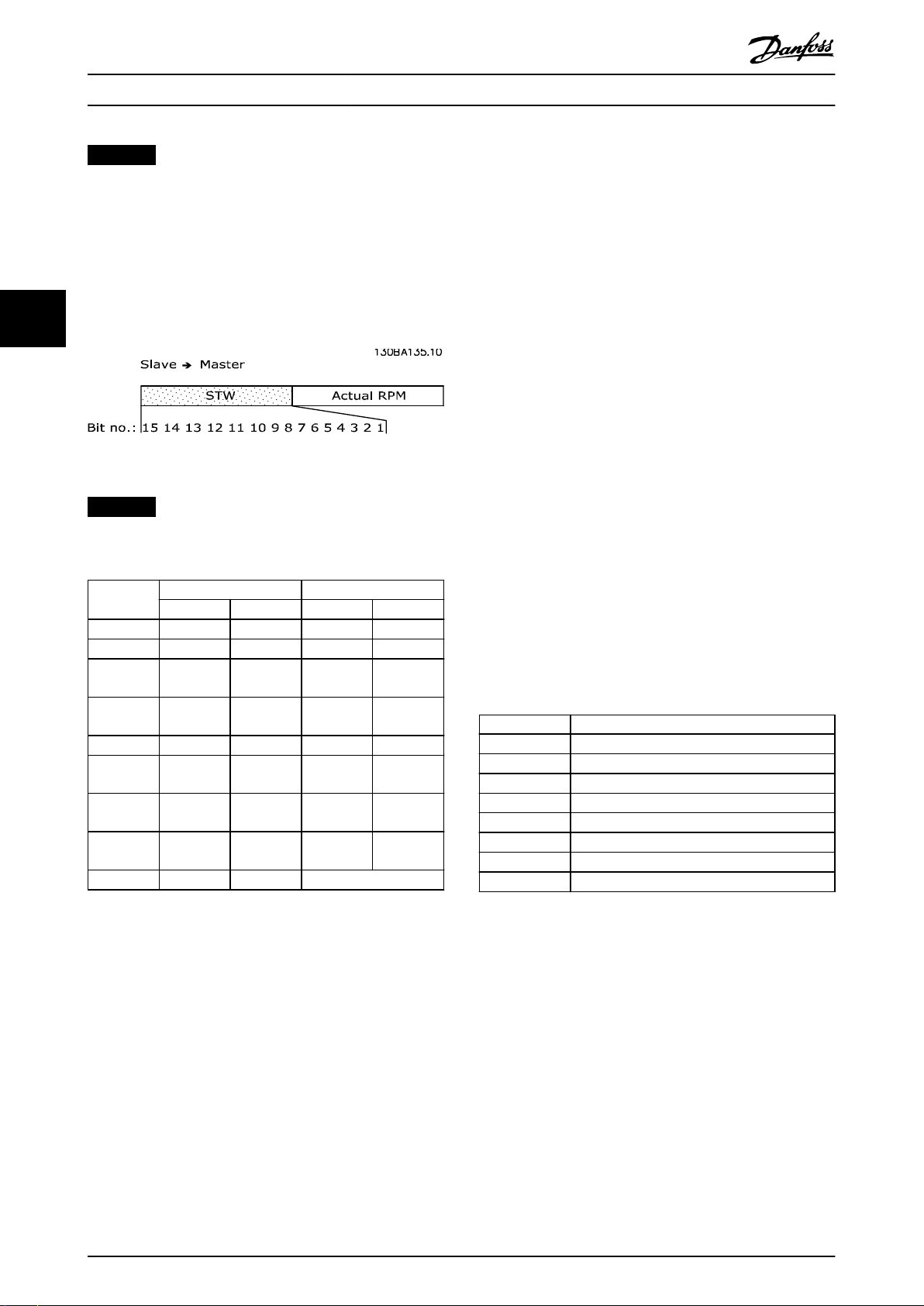
4.5.4 Actual Output Frequency under
Instances 100/150 and 101/151
The value of the actual output frequency of the frequency
converter is transmitted in the form of a 16-bit word. The
value is transmitted as a whole number (-32767 to
+32767). Negative gures are formed by 2’s complement.
Slave ⇒ master
STW Actual reference RPM
Table 4.10 Actual Output Frequency
16 bit
The actual output frequency has the following format:
-32767 to +32767.
-16384 (C000 hex) corresponds to -100%, and 16384 (4000
hex) corresponds to 100%.
16 Danfoss A/S © 12/2015 All rights reserved. MG92F102

Parameter Access Programming Guide
5 Parameter Access
5.1 Explicit Messages
DeviceNet is based on the CAN protocol. Every message contains an 11 bit CAN identier eld to dene the connection ID.
These CAN identiers are also used to determine access priority.
The MAC ID is stored in the header of the message, which is split into 4
10 9 8 7 6 5 4 3 2 1 0 Identier bits
0 Group 1 ID Source MAC ID Message group 1
1 0 MAC ID Group 2 ID Message group 2
1 1 Group 3 ID Source MAC ID Message group 3
1 1 1 1 1 Group 4 ID Message group 4
1 1 1 1 1 1 1 X X X X Invalid CAN identiers
Table 5.1 MAC ID
It is possible to access frequency converter parameters via the standard DeviceNet service explicit message. Two classes of
explicit messages are supported:
Message group 2: Explicit messages take place via
Message group 3: Explicit messages take place via dynamically established lower prioritized connections.
Object Classes
5.2
Access is available to the following standard DeviceNet objects.
Class ID 01h Identity object Class ID 10h Parameter group object
Class ID 03h DeviceNet object Class ID 28h Motor data object
Class ID 04h Assembly object Class ID 29h Control supervisory object
Class ID 05h Connection object Class ID 2Ah AC/DC drive object
Class ID 0Fh Parameter object Class ID 2Bh Acknowledge handler object
pre-dened master/slave connections.
dierent message groups, see Table 5.1.
5 5
Table 5.2 Standard DeviceNet Objects
The following DeviceNet vendor-specic objects are also available:
Class ID 100d to 119d Danfoss classes.
The object classes are described in chapter 5.3 DeviceNet Object Classes and chapter 5.4 Danfoss Object Classes.
MG92F102 Danfoss A/S © 12/2015 All rights reserved. 17

Parameter Access
VLT® DeviceNet MCA 104
5.3 DeviceNet Object Classes
5.3.1 Class ID 01h Identity Object
Class ID 01h identity object is a standard DeviceNet object for identication of the device (frequency converter). Set the
heartbeat interval in this object. The attributes supported for this class are listed in Table 5.3.
Attribute Access Name Data type Minimum/
Maximum
1 Get Vendor USINT – – 97 Danfoss Drives Vendor
55
2 Get Device Type UNIT – – 2 AD/DC Motor.
3 Get Product Code UNIT – – 100 See chapter 3.2.1 EDS File.
4 Get Revision UNIT – – – Software version on FC
5 Get Status UNIT – – –
6 Get Serial Number UDINT – – – From frequency
7 Get Product Name String – – – FC 100, FC 202, or FC
10 Get/Set Heartbeat
Interval
Table 5.3 Class ID 0x01
USINT 0–255 s 0 O.
Units Default Description
code.
102, FC 202, or FC 300.
converter.
300.
5.3.2 Class ID 03h DeviceNet Object
Class ID 03h DeviceNet object is a standard DeviceNet object for conguration and status of the DeviceNet connection. The
attributes supported for this class are listed in Table 5.4.
Attribute Access Name Data type Minimum/
Maximum
1 Get/Set MAC ID USINT 0–63 – 63 Node address.
2 Get/Set Baud rate USINT 0–2 – 0 0=125
4 Get BOC – – – – Bus-o counter.
5 Get Allocate
information
6 Get MAC ID switch
changed
7 Get Baud rate
switched from
last power-up
– – – – Only required if
BOOL 0–1 – 0 The node address switch
BOOL 0–1 – 0 The baud rate switch has
Units Default Description
1=250
2=500
predened master/slave
is implemented.
has changed since the
last power-up/reset.
changed since the last
power-up.
Table 5.4 Class ID 0x03
18 Danfoss A/S © 12/2015 All rights reserved. MG92F102

Parameter Access Programming Guide
5.3.3 Class ID 04h Assembly Object
Class ID 04h assembly object is a standard DeviceNet object for transfer of the I/O instances (process data) described in
chapter 4 Control. Using class ID 04h assembly object to send or read any of the dened instances, either by polling or
explicit messaging. The attributes supported for this class are listed in Table 5.5.
Attribute Access Name Data type Minimum/
Maximum
3 Set Data ARRAY – – – –
Table 5.5 Class ID 0x04
Instance Access Size Description Parameter 10-10 selection
20 Set 2 words DeviceNet AC/DC prole Instance 20/70
21 Set 2 words DeviceNet AC/DC prole Instance 21/71
70 Get 2 words DeviceNet AC/DC prole Instance 20/70
71 Get 2 words DeviceNet AC/DC prole Instance 21/71
100 Set 2 words Danfoss specic, no PCD words Instance 100/150
101 Set 4 words Danfoss specic, 2 PCD words Instance 101/151
150 Get 2 words Danfoss specic, no PCD words Instance 100/150
151 Get 4 words Danfoss specic, 2 PCD words Instance 101/151
Table 5.6 Instances
Units Default Description
5 5
MG92F102 Danfoss A/S © 12/2015 All rights reserved. 19

Parameter Access
VLT® DeviceNet MCA 104
5.3.4 Class ID 05h Connection Object
Class ID 05h connection object is a standard DeviceNet object for allocation and managing I/O and explicit messaging
connections. For this class, 3 instances are supported:
Explicit messages.
•
Polled I/O.
•
Change of state.
•
The attributes supported for the
Attribute Access Name Data type Description
55
1 Get State USINT State of the object.
2 Get Instance type USINT Indicates either I/O or explicit message.
3 Get Transport class
4 Get Produced
5 Get Consumed
6 Get Initial
7 Get Produced
8 Get Consumed
9 Get/Set Expected
12 Get Watchdog
13 Get Produced
14 Get Produced
15 Get Consumed
16 Get Consumed
17 Get Production
dierent instances are listed in Table 5.7, Table 5.8, and Table 5.9.
USINT Denes behavior of the connection.
trigger
UINT CAN identier eld when the connection transmits.
connection ID
UINT CAN identier eld value that denotes message to be received.
connection ID
USINT Denes the message group/groups across which productions and
communication
characteristics
UINT Maximum number of bytes transmitted across this connection.
connection size
UINT Maximum number of bytes received across this connection.
connection size
UINT Denes value used in transmission trigger timer and inactivity/
package rate
USINT Denes how to handle inactivity/watchdog timeout.
timeout action
UINT Number of bytes in the produced connection path attribute.
connection path
length
Array of USINT Species the application object/objects whose data is to be produced
connection path
UINT Number of bytes in the consumed connection path attribute.
connection path
length
Array of USINT Species the application object/objects that are to receive the data
connection path
UINT Denes minimum time between new data production. This attribute is
inhibit time
consumptions associated with this connection occur.
watchdog timer.
by these connection objects.
consumed by this connection object.
required for I/O client connection.
Table 5.7 Instance 1 Attributes: Explicit Message Instance
20 Danfoss A/S © 12/2015 All rights reserved. MG92F102

Parameter Access Programming Guide
Attribute Access Name Data type Description
1 Get State USINT State of the object.
2 Get Instance type USINT Indicates either I/O or explicit message.
3 Get Transport class
trigger
4 Get Produced
connection ID
5 Get Consumed
connection ID
6 Get Initial
communication
characteristics
7 Get Produced
connection size
8 Get Consumed
connection size
9 Get/Set Expected
package rate
12 Get Watchdog
timeout action
13 Get Produced
connection path
length
14 Get Produced
connection path
15 Get Consumed
connection path
length
16 Get Consumed
connection path
17 Get Production
inhibit time
USINT Denes behavior of the connection.
UINT CAN identier eld when the connection transmits.
UINT CAN identier eld value that denotes message to be received.
USINT Denes the message group/groups across which productions and
consumptions associated with this connection occur.
UINT Maximum number of bytes transmitted across this connection.
UINT Maximum number of bytes received across this connection.
UINT Denes value used in transmission trigger timer and inactivity/
watchdog timer.
USINT Denes how to handle inactivity/watchdog timeout.
UINT Number of bytes in the produced connection path attribute.
Array of USINT Species the application object/objects whose data is to be produced
by these connection objects.
UINT Number of bytes in the consumed connection path attribute.
Array of USINT Species the application object/objects that are to receive the data
consumed by this connection object.
UINT Denes minimum time between new data production. This attribute is
required for I/O client connection.
5 5
Table 5.8 Instance 2 Attributes: Polled I/O
MG92F102 Danfoss A/S © 12/2015 All rights reserved. 21

Parameter Access
Attribute Access Name Data type Description
1 Get State USINT State of the object.
2 Get Instance type USINT Indicates either I/O or explicit message.
3 Get Transport class
trigger
4 Get Produced
connection ID
5 Get Consumed
connection ID
6 Get Initial
communication
55
7 Get Produced
8 Get Consumed
9 Get/Set Expected
12 Get Watchdog
13 Get Produced
14 Get Produced
15 Get Consumed
16 Get Consumed
17 Get Production
characteristics
connection size
connection size
package rate
timeout action
connection path
length
connection path
connection path
length
connection path
inhibit time
VLT® DeviceNet MCA 104
USINT Denes behavior of the connection.
UINT CAN identier eld when the connection transmits.
UINT CAN identier eld value that denotes message to be received.
USINT Denes the message group/groups across which productions and
consumptions associated with this connection occur.
UINT Maximum number of bytes transmitted across this connection.
UINT Maximum number of bytes received across this connection.
UINT Denes value used in transmission trigger timer and inactivity/
watchdog timer.
USINT Denes how to handle inactivity/watchdog timeout.
UINT Number of bytes in the produced connection path attribute.
Array of USINT Species the application object/objects whose data is to be produced
by these connection objects.
UINT Number of bytes in the consumed connection path attribute.
Array of USINT Species the application object/objects that are to receive the data
consumed by this connection object.
UINT Denes minimum time between new data production. This attribute is
required for I/O client connection.
Table 5.9 Instance 4: Change of State/Cycle
22 Danfoss A/S © 12/2015 All rights reserved. MG92F102

Parameter Access Programming Guide
5.3.5 Class ID 0F4 Parameter Object
Class ID 0F4 parameter object is an interface to the parameters of the frequency converter. It identies congurable
parameters and supplies their description, including minimum and maximum values and a descriptive text. The attributes
supported are listed in Table 5.10.
Attribute Access Stub/Full Name Data type Description
1 Set/Get Stub Parameter value
2 Get Stub Link path size USINT Size of link path.
3 Get Stub Link path ARRAY DeviceNet's path to origin of the parameters.
– – – Segment type/port BYTE –
– – – Segment address Path –
4 Get Stub Descriptor WORD Description of parameter.
5 Get Stub Data type EPATH Data type code.
6 Get Stub Data size USINT Number of bytes in parameter value.
7 Get Full Parameter name
string
8 Get Full Units string SHORT
9 Get/Set Full Help string SHORT
10 Get Full Minimum value
11 Get Full Maximum value
12 Get Full Default value
13 Get Full Scaling multiplier UINT Multiplier for scaling factor.
14 Get Full Scaling divisor UINT Divisor for scaling factor.
15 Get Full Scaling base UINT Base for scaling formula.
16 Get Full Scaling oset INT Oset for scaling formula.
17 Get Full Multiplier link UINT Parameter instance of multiplier source.
18 Get Full Divisor link UINT Parameter instance of divisor source.
19 Get Full Base link UINT Parameter instance of base source.
20 Get Full Oset link UINT Parameter instance of oset source.
21 Get Full Decimal precision USINT Species parameter value format.
Data type
SHORT
STRING
STRING
STRING
Data type
Data type
Data type
1)
1)
1)
1)
Actual value of parameter.
Text string representing the parameter name.
Text string representing the parameter name.
Text string representing the parameter name.
Minimum valid value.
Maximum valid value.
Parameters default value.
5 5
Table 5.10 Attributes Supported for Class ID 0F4 Parameter Object
1) Same data type as the parameter.
MG92F102 Danfoss A/S © 12/2015 All rights reserved. 23

Parameter Access
VLT® DeviceNet MCA 104
5.3.6 Class ID 10h Parameter Group Object
Class ID 10h parameter group object denes 14 parameter groups for all parameters of the frequency converters. One class
instance exists for each parameter group. A readout of an instance contains the name of the current parameter group.
Group Instance Name (maximum 16 characters)
0 1 O P E R A T I O N D I S P L .
1 2 L O A D – M O T O R – – – – – –
2 3 B R A K E S – – – – – – – – – –
3 4 R E F E R E N C E – R A M P S –
4 5 L I M I T S – W A R N I N G S –
55
5 6 D I G I T A L – I N – O U T – –
6 7 A N A L O G – I N – O U T – – –
7 8 C O N T R O L L E R S – – – – –
8 9 C O M M . – A N D – O P T I O N
9 10 C A N – F I E L D B U S – – – –
10 11 S P E C I A L – F U N C T I O N
Table 5.11 Class ID 10h Parameter Group Object
5.3.7 Class ID 28h Motor Data Object
In class ID 28h motor data object, the current motor data can be congured and readout. The instances, attributes, and
services supported for this class are listed in Table 5.12.
Attribute Access Name Data
type
3 Get/set Motor
type
6 Get/set Rated
current
7 Get/set Rated
voltage
8 Get/set Rated
power
9 Get/set Rated
frequency
1)
12
15 Get/set Base
Get/set Pole
count
speed
USINT 7 – 7 7 = Squirrel cage
UNIT 0–100.00 100 mA Drive dependent Stator current rating (from
UNIT 200–500 Volt Drive dependent Base voltage rating (from
UDINT 0–18500 Watt Drive dependent Power rating at rated
UNIT 1–1000 Hz Drive dependent Elec. frequency rating
UINT – – Drive dependent Pole numbers in the
UNIT 100–60000 RPM Drive dependent Nominal motor speed
Generic
maximum
values
Units Default Description Parameter
reference
Parameter 1-10 Motor
asynchronous motor
motor nameplate)
motor nameplate)
frequency (from motor
nameplate)
(from motor nameplate)
motor
(from motor nameplate)
Construction
Parameter 1-24 Motor
Current
Parameter 1-22 Motor
Voltage
Parameter 1-20 Motor
Power [kW]
Parameter 1-23 Motor
Frequency
Parameter 1-39 Motor
Parameter 1-25 Motor
Nominal Speed
Poles
Table 5.12 Class ID 0x28
24 Danfoss A/S © 12/2015 All rights reserved. MG92F102

Parameter Access Programming Guide
5.3.8 Class ID 29h Control Supervisory Object
The control supervisory object can be used for process control and monitoring of the frequency converter as an alternative
to the I/O instances dened in chapter 4 Control. The attributes supported for this class are listed in Table 5.13.
Attribute Access Name Data type Minimum/
Maximum
3 Get/Set Run 1 Bool 0–1 – Run fwd, see note below
4 Get/Set Run 2 Bool 0–1 – Run rev, see note below
5 Get/Set NetCtrl Bool 0–1 1 0 = Local control
6 Get State USINT 0–7 – 0 = Vendor specic
7 Get Running 1 Bool 0–1 0 0 = Other state
8 Get Running 2 Bool 0–1 0 0 = Other state
9 Get Ready Bool 0–1 – 0 = Other state
10 Get Fault Bool 0–1 0 0 = No faults present
12 Get/Set Fault Rst Bool 0–1 – 0 = No action
13 Get Fault Code UINT – –
15 Get Ctrl From Net Bool 0–1 1 0 = Control is local
16 Get/Set DN Fault Mode UINT 0–2 1 Action on loss of DeviceNet
Default Description
1 = Control from network
1 = Start-up
2 = Not ready
3 = Ready
4 = Enabled
5 = Stop
6 = Fault stop
7 = Fault
1 = (Enable and Run 1)
or (Stopping and Running 1)
or (Fault Stop and Running 1)
1 = (Enable and Run 2)
or (Stopping and Running 2)
or (Fault Stop and Running 2)
1 = Ready or Enabled or Stopping
1 = Fault occurred (latched)
1 ->1 = Reset fault
1 = Control is from network
0 = Fault + Stop
1 = Ignore (warning optional)
2 = Danfoss specic
5 5
Table 5.13 Class ID 0x29
NOTICE
The ODVA drive prole selected in parameter 1-10 Motor Construction is available only when instances 20/70 or 21/71
are selected.
Illustration 5.1 shows how the frequency converter responds to the various command attributes associated with class ID
0x29.
MG92F102 Danfoss A/S © 12/2015 All rights reserved. 25

Parameter Access
VLT® DeviceNet MCA 104
55
Illustration 5.1 State – Transition Diagram
5.3.9 Class ID 2Ah AC/DC Drive Object
To set and read out a range of frequency converters control and status information, use this object. The attributes
supported for this class are listed in Table 5.14.
Attribute Access Name Data
type
3 Get At reference Bool 0–1 – 0 = Drive not at reference
4 Get/Set Net ref Bool 0–1 1 0 = Set reference at non-DeviceNet
6 Get/Set Drive mode USINT 0–1 1 0 = Vendor specic mode
7 Get Speed actual INT –
8 Get/Set Speed ref INT –
22 Get/Set Speed scale SINT -128–127 – Speed scaling factor
29 Get Ref from net Bool 0–1 – 0 = Local speed reference
Minimum/
Maximum
Default Description
1 = Drive at reference
reference
1 = Set reference at DeviceNet reference
1 = Open-loop speed (frequency)
2 = Closed-loop speed control
RPM/2
RPM/2
Speed Scale
Speed Scale
Actual drive speed
(best approximation)
Speed reference
1 = DeviceNet speed reference
Table 5.14 Class ID 0x2A
26 Danfoss A/S © 12/2015 All rights reserved. MG92F102

Parameter Access Programming Guide
5.3.10 Class ID 2Bh Acknowledge Handler Object
To manage message reception acknowledgements, necessary for change-of-state support, use class ID 2Bh acknowledge
handler object. The attributes supported for this class are listed in Table 5.15.
Attribute Access Name Data
type
1 Set ACK timer UINT 0–65535 16 Time to wait for ACK before resending.
2 Get/Set Retry timer USINT 0–255 1 Number of ACK-timeouts to wait before
3 Get/Set COS UINT – – Connection instance ID
Table 5.15 Class ID 0x2B
5.4 Danfoss Object Classes
Use the Danfoss classes for read and write of all parameter
values of the frequency converters. A corresponding object
class is dened for each parameter group. Table 5.16 shows
the classes supported, and their relationship to the
parameters.
The class instance and attribute act in the following way:
100 added to the parameter group = the value
•
for the class.
100 added to the remaining parameter number =
•
the value for the instance.
100 added to the array index of the parameter =
•
the value for the attribute.
Parameter range Class
Parameter 0-00 – 0-99 Class 100
Parameter 1-00 – 1-99 Class 101
Parameter 2-00 – 2-99 Class 102
Parameter 3-00 – 3-99 Class 103
Parameter 4-00 – 4-99 Class 104
Parameter 5-00 – 5-99 Class 105
Parameter 6-00 – 6-99 Class 106
Parameter 7-00 – 7-99 Class 107
Parameter 8-00 – 8-99 Class 108
Parameter 10-00 – 10-99 Class 110
Parameter 11-00 – 11-99 Class 111
Parameter 13-00 – 13-99 Class 113
Parameter 14-00 – 14-99 Class 114
Parameter 15-00 – 15-99 Class 115
Parameter 16-00 – 16-99 Class 116
Minimum/
Maximum
Default Description
producing.
RetryLimit_Reache event.
5.4.1 Examples
Examples: (ctitious parameters) (all values in decimal)
Parameter 0-01 Language [index 0] = Class 100;
•
instance 101; attribute 100
Parameter 1-00 Conguration Mode [index 0] =
•
Class 101; instance 100; attribute 100
Parameter 3-41 Ramp 1 Ramp Up Time [index 0] =
•
Class 103; instance 141; attribute 100
Parameter 1-55 U/f Characteristic - U [index 3] =
•
Class 101; instance 155; attribute 103
Parameter 6-54 Terminal 42 Output Timeout Preset
•
[index 9] = Class 106; instance 154; attribute 109
Parameter 10-01 Baud Rate Select [index 0] = Class
•
110; instance 101; attribute 100
5 5
Table 5.16 Danfoss Classes
MG92F102 Danfoss A/S © 12/2015 All rights reserved. 27

Parameters
6 Parameters
VLT® DeviceNet MCA 104
6
6.1 Parameter Description
8-01 Control Site
Option: Function:
The setting in this parameter overrides the
settings in parameter 8-50 Coasting Select to
parameter 8-56 Preset Reference Select.
[0] Digital and
ctrl.word
[1] Digital only Control by using digital inputs only.
[2] Controlword
only
Control by using both digital input and
control word.
Control by using control word only.
8-02 Control Word Source
Option: Function:
NOTICE
This parameter cannot be adjusted
while the motor is running.
Select the source of the control word: 1 of 2
serial interfaces or 4 installed options. During
initial power-up, the frequency converter
automatically sets this parameter to [3] Option
A, if it detects a valid
in slot A. When the option is removed, the
frequency converter detects a conguration
change, sets parameter 8-02 Control Word
Source to default setting [1] FC RS485, and
trips. If an option is installed after initial
power-up, the setting of
parameter 8-02 Control Word Source does not
change, but the frequency converter trips and
shows: Alarm 67, Option Changed.
When retrotting a bus option into a
frequency converter that did not have a bus
option installed earlier, change the control to
bus-based. This change is required for safety
reasons to avoid an unintended change.
[0] None
[1] FC RS485
[2] FC USB
[3] Option A
[4] Option B
[5] Option C0
[6] Option C1
[30] External Can
eldbus option installed
8-03 Control Word Timeout Time
Range: Function:
1 s* [ 0.1 -
18000 s]
Enter the maximum time expected to pass
between the reception of 2 consecutive
telegrams. If this time is exceeded, it indicates
that the telegram communication has stopped.
The function selected in parameter 8-04 Control
Word Timeout Function is then carried out. A
valid control word triggers the timeout counter.
8-04 Control Word Timeout Function
Select the timeout function. The timeout function activates when
the control word fails to be updated within the time period
specied in parameter 8-03 Control Word Timeout Time.
Option: Function:
NOTICE
To change the set-up after a timeout,
congure as follows:
Set parameter 0-10 Active Set-up to [9]
Multi set-up and select the relevant
link in parameter 0-12 This Set-up
Linked to.
[0] O Resumes control via eldbus (eldbus or
standard), using the most recent control
word.
[1] Freeze output Freezes output frequency until communi-
cation resumes.
[2] Stop Stops with auto restart when communi-
cation resumes.
[3] Jogging Runs the motor at jog frequency until
communication resumes.
[4] Max. speed Runs the motor at maximum frequency until
communication resumes.
[5] Stop and trip Stops the motor, then resets the frequency
converter to restart:
Via the eldbus.
•
Via [Reset].
•
Via a digital input.
•
[7] Select setup 1 Changes the set-up after a control word
timeout. If communication resumes after a
timeout, parameter 8-05 End-of-Timeout
Function denes whether to resume the set-
up used before the timeout, or to retain the
set-up endorsed by the timeout function.
[8] Select setup 2 See [7] Select set-up 1.
[9] Select setup 3 See [7] Select set-up 1.
[10] Select setup 4 See [7] Select set-up 1.
28 Danfoss A/S © 12/2015 All rights reserved. MG92F102

Parameters Programming Guide
8-04 Control Word Timeout Function
Select the timeout function. The timeout function activates when
the control word fails to be updated within the time period
specied in parameter 8-03 Control Word Timeout Time.
Option: Function:
[26] Trip
8-05 End-of-Timeout Function
Option: Function:
Select the action after receiving a valid control
word following a timeout.
This parameter is active only when
parameter 8-04 Control Timeout Function is set
to:
[7] Set-up 1.
•
[8] Set-up 2.
•
[9] Set-up 3.
•
[10] Set-up 4.
•
[0] Hold set-upRetains the set-up selected in
parameter 8-04 Control Timeout Function and
shows a warning until parameter 8-06 Reset
Control Timeout toggles. Then the frequency
converter resumes its original set-up.
[1] * Resume
set-up
Resumes the set-up that was active before the
timeout.
8-06 Reset Control Word Timeout
This parameter is active only when [0] Hold set-up has been
selected in parameter 8-05 End-of-Timeout Function.
Option: Function:
[0] * Do not reset Retains the set-up specied in
parameter 8-04 Control Word Timeout Function,
following a control word timeout.
[1] Do reset Restores the frequency converter to the
original set-up following a control word
timeout. The frequency converter performs
the reset and then immediately reverts to the
[0] Do not reset setting.
8-07 Diagnosis Trigger
This parameter has no function for DeviceNet.
Option: Function:
[0] * Disable
[1] Trigger on alarms
[2] Trigger alarm/warn.
8-08 Readout Filtering
If the speed feedback value readouts on eldbus are uctuating,
this function is used. Select ltered, if the function is required. A
power cycle is required for changes to take eect.
Option: Function:
[0] Motor Data
Std-Filt.
Normal eldbus readouts.
8-08 Readout Filtering
If the speed feedback value readouts on eldbus are uctuating,
this function is used. Select ltered, if the function is required. A
power cycle is required for changes to take eect.
Option: Function:
[1] Motor Data
LP-Filter
Filtered eldbus readouts of the following
parameters:
Parameter 16-10 Power [kW ].
•
Parameter 16-11 Power [hp].
•
Parameter 16-12 Motor Voltage.
•
Parameter 16-14 Motor current.
•
Parameter 16-16 Torque [Nm].
•
Parameter 16-17 Speed [RPM].
•
Parameter 16-22 Torque [%].
•
Parameter 16-25 Torque [Nm] High.
•
8-10 Control Word Prole
Instances 20/70 and 21/71 are selectable in
parameter 10-10 Process Data Type Selection.
Option: Function:
[0] * FC prole Instances 100/150 and 101/151 are
selectable in parameter 10-10 Process
Data Type Selection.
[1] PROFIdrive prole
[5] ODVA
[7] CANopen DSP 402
[8] MCO
8-13 Congurable Status Word STW
The status word has 16 bits (0–15). Bits 5 and 12–15 are cong-
urable. Each of these bits can be congured to any of the
following options.
Option: Function:
[0] No function The input is always low.
[1] Prole Default Depending on the prole set in
parameter 8-10 Control Prole.
[2] Alarm 68 Only The input goes high whenever
alarm 68, Safe Stop activated is
active, and goes low whenever
alarm 68 Safe Stop activated is not
activate.
[3] Trip excl Alarm 68
[10] T18 DI status
[11] T19 DI status
[12] T27 DI status
[13] T29 DI status
[14] T32 DI status
[15] T33 DI status
[16] T37 DI status The input goes high whenever
terminal 37 has 0 V and goes low
whenever terminal 37 has 24 V.
6
6
MG92F102 Danfoss A/S © 12/2015 All rights reserved. 29

Parameters
VLT® DeviceNet MCA 104
6
8-13 Congurable Status Word STW
The status word has 16 bits (0–15). Bits 5 and 12–15 are cong-
urable. Each of these bits can be congured to any of the
following options.
Option: Function:
[21] Thermal warning
[30] Brake fault (IGBT)
[40] Out of ref range
[41] Load throttle active
[60] Comparator 0
[61] Comparator 1
[62] Comparator 2
[63] Comparator 3
[64] Comparator 4
[65] Comparator 5
[70] Logic Rule 0
[71] Logic Rule 1
[72] Logic Rule 2
[73] Logic Rule 3
[74] Logic Rule 4
[75] Logic Rule 5
[80] SL digital out A
[81] SL digital out B
[82] SL digital out C
[83] SL digital out D
[84] SL digital out E
[85] SL digital out F
[86] ATEX ETR cur. alarm
[87] ATEX ETR freq. alarm
[88] ATEX ETR cur. warning
[89] ATEX ETR freq. warning
[90] Safe Function active
[91] Safe Opt. Reset req.
[92] IGBT-cooling See 5-3* Digital Outputs.
8-14 Congurable Control Word CTW
Array [15]
Option: Function:
This parameter is not valid in software versions
before 4.93.
[0] None The frequency converter ignores the information
in this bit.
[1]*Prole
default
[2] CTW
Valid,
active
low
[3] Safe
Option
Reset
The functionality of the bit is depending on the
selection parameter 8-10 Control Word Prole.
If set to 1, the frequency converter ignores the
remaining bits of the control word.
This function is only available in bits 12–15 of
the control word, if a safety option is mounted
in the frequency converter. The reset is executed
on a 0⇒1 transition, and resets the safety option
as set in parameter 42-24 Restart Behaviour.
8-14 Congurable Control Word CTW
Array [15]
Option: Function:
[4] PID error
inverse
[5] PID reset
I part
[6] PID
enable
Inverts the resulting error from the process PID
controller. Available only if
parameter 1-00 Conguration Mode is set to [6]
Surface Winder, [7] Extended PID Speed OL, or [8]
Extended PID Speed CL.
Resets the I-part of the process PID controller.
Equivalent to parameter 7-40 Process PID I-part
Reset. Available only if parameter 1-00 Congu-
ration Mode is set to [6] Surface Winder, [7]
Extended PID Speed OL, or [8] Extended PID Speed
CL.
Enables the extended process PID controller.
Equivalent to parameter 7-50 Process PID
Extended PID. Available only if
parameter 1-00 Conguration Mode is set to [6]
Surface Winder, [7] Extended PID Speed OL, or [8]
Extended PID Speed CL.
8-19 Product Code
Range: Function:
Size
related*
[0 -
2147483647]
Select 0 to read out the actual
eldbus product code according
to the mounted eldbus option.
Select 1 to read out the actual
vendor ID.
8-46 BTM Transaction Status
Option: Function:
[0] * O
[1] Transaction Started
[2] Transaction Comitting
[3] Transaction Timeout
[4] Err. Non-existing Par.
[5] Err. Par. Out of Range
[6] Transaction Failed
8-47 BTM Timeout
Range: Function:
60 s* [1 - 360 s] Select the BTM timeout after a BTM
transaction has been started.
8-48 BTM Maximum Errors
Range: Function:
21* [0 - 21] Selects the maximum allowed number of bulk
transfer mode errors before aborting. If it is set to
maximum, there is no abort.
30 Danfoss A/S © 12/2015 All rights reserved. MG92F102

Parameters Programming Guide
8-49 BTM Error Log
Range: Function:
0.255* [0.000 -
9999.255]
List of parameters that failed during
bulk transfer mode. The value after the
decimal break is the fault code (255
stands for no error).
8-50 Coasting Select
Option: Function:
Select control of the coasting function via the
terminals (digital input) and/or via the bus.
[0] Digital
input
[1] Bus Activates start command via the serial
[2] Logic AND Activates start command via the eldbus/serial
[3] * Logic OR Activates start command via the eldbus/serial
Activates start command via a digital input.
communication port or eldbus option.
communication port and 1 extra digital input.
communication port or via 1 of the digital
inputs.
8-51 Quick Stop Select
Select control of the quick stop function via the terminals (digital
input) and/or via the bus.
Option: Function:
[0] Digital input
[1] Bus
[2] Logic AND
[3] * Logic OR
8-52 DC Brake Select
Option: Function:
Select control of the DC brake via the terminals
(digital input) and/or via the eldbus.
NOTICE
When parameter 1-10 Motor Construction is
set to [1] PM non-salient SPM, only selection
[0] Digital input is available.
[0] Digital
input
[1] Bus Activates a start command via the serial communi-
[2] Logic
AND
[3] Logic OR Activates a start command via the eldbus/serial
Activates a start command via a digital input.
cation port or eldbus option.
Activates a start command via the eldbus/serial
communication port, and also via 1 of the digital
inputs.
communication port, or via 1 of the digital inputs.
8-53 Start Select
Option: Function:
Select control of the frequency converter start
function via the terminals (digital input) and/or
via the eldbus.
[0] Digital
input
[1] Bus Activates a start command via the serial
[2] Logic
AND
[3] * Logic OR Activates a start command via the eldbus/
Activates a start command via a digital input.
communication port or eldbus option.
Activates a start command via the eldbus/
serial communication port and also via 1 of the
digital inputs.
serial communication port or via 1 of the digital
inputs.
8-54 Reversing Select
Option: Function:
[0] Digital
input
[1] Bus Activates the reverse command via the serial
[2] Logic AND Activates the reverse command via the eldbus/
[3] Logic OR Activates the reverse command via the eldbus/
Select control of the frequency converter reverse
function via the terminals (digital input) and/or
via the eldbus.
communication port or eldbus option.
serial communication port and also via 1 of the
digital inputs.
serial communication port or via 1 of the digital
inputs.
8-55 Set-up Select
Option: Function:
Select control of the frequency converter set-up
selection via the terminals (digital input) and/or
via the eldbus.
[0] Digital
input
[1] Bus Activates the set-up selection via the serial
[2] Logic
AND
[3] * Logic OR Activates the set-up selection via the eldbus/
Activates the set-up selection via a digital input.
communication port or eldbus option.
Activates the set-up selection via the eldbus/
serial communication port and via 1 of the
digital inputs.
serial communication port or via 1 of the digital
inputs.
8-56 Preset Reference Select
Option: Function:
Select control of the preset reference selection
via the terminals (digital input) and/or via the
eldbus.
6
6
MG92F102 Danfoss A/S © 12/2015 All rights reserved. 31

Parameters
VLT® DeviceNet MCA 104
6
8-56 Preset Reference Select
Option: Function:
[0] Digital
input
[1] Bus Activates preset reference selection via the
[2] Logic AND Activates preset reference selection via the
[3] * Logic OR Activates the preset reference selection via the
Activates preset reference selection via a digital
input.
serial communication port or eldbus option.
eldbus/serial communication port and via 1 of
the digital inputs.
eldbus/serial communication port or via 1 of
the digital inputs.
8-90 Bus Jog 1 Speed
Range: Function:
100 RPM* [ 0 - par. 4-13
RPM]
Enter the jog speed. Activate this
xed jog speed via the serial port
or eldbus option.
8-91 Bus Jog 2 Speed
Range: Function:
200 RPM* [ 0 - par. 4-13
RPM]
Enter the jog speed. Activate this
xed jog speed via the serial port
or eldbus option.
10-00 CAN Protocol
Option: Function:
NOTICE
The options depend on the installed
option.
[0] CANopen
[1] DeviceNet View the active CAN protocol.
10-01 Baud Rate Select
Select the eldbus transmission speed. The selection must
correspond to the transmission speed of the master and the
other eldbus nodes.
Option: Function:
[16] 10 Kbps
[17] 20 Kbps
[18] 50 Kbps
[19] 100 Kbps
[20] 125 Kbps
[21] 250 Kbps
[22] 500 Kbps
10-02 MAC ID
Range: Function:
Size related* [ 0 - 63 ] Selection of station address. Every
station connected to the same
DeviceNet network must have an
unambiguous address.
10-05 Readout Transmit Error Counter
Range: Function:
0* [0 - 255 ] View the number of CAN control transmission
errors since the last power-up.
10-06 Readout Receive Error Counter
Range: Function:
0* [0 - 255 ] View the number of CAN control receipt errors
since the last power-up.
10-07 Readout Bus O Counter
Range: Function:
0* [0 - 255 ] View the number of eldbus o events since the
last power-up.
10-10 Process Data Type Selection
Option: Function:
Select the instance (telegram) for data
transmission. The instances available depend
on the setting of parameter 8-10 Control
Prole.
When parameter 8-10 Control Prole is set to
[0] FC prole, parameter 10-10 Process Data
Type Selection options [0] INSTANCE 100/150
and [1] INSTANCE 101/151 are available.
When parameter 8-10 Control Prole is set to
[5] ODVA, parameter 10-10 Process Data Type
Selection options [2] INSTANCE 20/70 and [3]
INSTANCE 21/71 are available.
Instances 100/150 and 101/151 are Danfoss-
specic. Instances 20/70 and 21/71 are ODVA-
specic AC motor proles.
For guidelines in telegram selection, refer to
the VLT® DeviceNet MCA 104 Installation Guide.
NOTICE
A change to this parameter is executed
immediately.
[0] INSTANCE
100/150
[1] INSTANCE
101/151
[2] INSTANCE
20/70
[3] INSTANCE
21/71
10-11 Process Data Cong Write
Select the process write data for I/O assembly instances 101/151.
Elements [2] and [3] of this array can be selected. Elements [0]
and [1] of the array are xed.
Option: Function:
[0] None
[302] Minimum Reference
32 Danfoss A/S © 12/2015 All rights reserved. MG92F102

Parameters Programming Guide
10-11 Process Data Cong Write
Select the process write data for I/O assembly instances 101/151.
Elements [2] and [3] of this array can be selected. Elements [0]
and [1] of the array are xed.
Option: Function:
[303] Maximum Reference
[312] Catch up/slow Down Value
[341] Ramp 1 Ramp Up Time
[342] Ramp 1 Ramp Down Time
[351] Ramp 2 Ramp Up Time
[352] Ramp 2 Ramp Down Time
[380] Jog Ramp Time
[381] Quick Stop Ramp Time
[411] Motor Speed Low Limit [RPM]
[412] Motor Speed Low Limit [Hz]
[413] Motor Speed High Limit [RPM]
[414] Motor Speed High Limit [Hz]
[416] Torque Limit Motor Mode
[417] Torque Limit Generator Mode
[553] Term. 29 High Ref./Feedb. Value
[558] Term. 33 High Ref./Feedb. Value
[590] Digital & Relay Bus Control
[593] Pulse Out #27 Bus Control
[595] Pulse Out #29 Bus Control
[597] Pulse Out #X30/6 Bus Control
[615] Terminal 53 High Ref./Feedb.
Value
[625] Terminal 54 High Ref./Feedb.
Value
[653] Term 42 Output Bus Ctrl
[663] Terminal X30/8 Bus Control
[673] Terminal X45/1 Bus Control
[683] Terminal X45/3 Bus Control
[748] PCD Feed Forward
[890] Bus Jog 1 Speed
[891] Bus Jog 2 Speed
[1680] Fieldbus CTW 1
[1682] Fieldbus REF 1
[1685] FC Port CTW 1
[1686] FC Port REF 1
10-12 Process Data Cong Read
Select the process read data for I/O assembly instances 101/151.
Elements [2] and [3] of this array can be selected. Elements [0]
and [1] of the array are xed.
Option: Function:
[0] None
[15] Readout: actual setup
[1472] Legacy Alarm Word
[1473] Legacy Warning Word
[1474] Leg. Ext. Status Word
[1500] Operating hours
[1501] Running Hours
[1502] kWh Counter
10-12 Process Data Cong Read
Select the process read data for I/O assembly instances 101/151.
Elements [2] and [3] of this array can be selected. Elements [0]
and [1] of the array are xed.
Option: Function:
[1600] Control Word
[1601] Reference [Unit]
[1602] Reference %
[1603] Status Word
[1605] Main Actual Value [%]
[1606] Absolute Position
[1609] Custom Readout
[1610] Power [kW]
[1611] Power [hp]
[1612] Motor Voltage
[1613] Frequency
[1614] Motor current
[1615] Frequency [%]
[1616] Torque [Nm]
[1617] Speed [RPM]
[1618] Motor Thermal
[1619] KTY sensor temperature
[1620] Motor Angle
[1621] Torque [%] High Res.
[1622] Torque [%]
[1623] Motor Shaft Power [kW]
[1624] Calibrated Stator Resistance
[1625] Torque [Nm] High
[1630] DC Link Voltage
[1632] Brake Energy /s
[1633] Brake Energy Average
[1634] Heatsink Temp.
[1635] Inverter Thermal
[1638] SL Controller State
[1639] Control Card Temp.
[1645] Motor Phase U Current
[1646] Motor Phase V Current
[1647] Motor Phase W Current
[1648] Speed Ref. After Ramp [RPM]
[1650] External Reference
[1651] Pulse Reference
[1652] Feedback[Unit]
[1653] Digi Pot Reference
[1657] Feedback [RPM]
[1660] Digital Input
[1661] Terminal 53 Switch Setting
[1662] Analog Input 53
[1663] Terminal 54 Switch Setting
[1664] Analog Input 54
[1665] Analog Output 42 [mA]
[1666] Digital Output [bin]
[1667] Freq. Input #29 [Hz]
[1668] Freq. Input #33 [Hz]
[1669] Pulse Output #27 [Hz]
6
6
MG92F102 Danfoss A/S © 12/2015 All rights reserved. 33

Parameters
VLT® DeviceNet MCA 104
6
10-12 Process Data Cong Read
Select the process read data for I/O assembly instances 101/151.
Elements [2] and [3] of this array can be selected. Elements [0]
and [1] of the array are xed.
Option: Function:
[1670] Pulse Output #29 [Hz]
[1671] Relay Output [bin]
[1672] Counter A
[1673] Counter B
[1674] Prec. Stop Counter
[1675] Analog In X30/11
[1676] Analog In X30/12
[1677] Analog Out X30/8 [mA]
[1678] Analog Out X45/1 [mA]
[1679] Analog Out X45/3 [mA]
[1684] Comm. Option STW
[1687] Bus Readout Alarm/Warning
[1689] Congurable Alarm/Warning Word
[1690] Alarm Word
[1691] Alarm Word 2
[1692] Warning Word
[1693] Warning Word 2
[1694] Ext. Status Word
[1836] Analog Input X48/2 [mA]
[1837] Temp. Input X48/4
[1838] Temp. Input X48/7
[1839] Temp. Input X48/10
[1843] Analog Out X49/7
[1844] Analog Out X49/9
[1845] Analog Out X49/11
[1860] Digital Input 2
[3421] PCD 1 Read from MCO
[3422] PCD 2 Read from MCO
[3423] PCD 3 Read from MCO
[3424] PCD 4 Read from MCO
[3425] PCD 5 Read from MCO
[3426] PCD 6 Read from MCO
[3427] PCD 7 Read from MCO
[3428] PCD 8 Read from MCO
[3429] PCD 9 Read from MCO
[3430] PCD 10 Read from MCO
[3440] Digital Inputs
[3441] Digital Outputs
[3450] Actual Position
[3451] Commanded Position
[3452] Actual Master Position
[3453] Slave Index Position
[3454] Master Index Position
[3455] Curve Position
[3456] Track Error
[3457] Synchronizing Error
[3458] Actual Velocity
[3459] Actual Master Velocity
[3460] Synchronizing Status
10-12 Process Data Cong Read
Select the process read data for I/O assembly instances 101/151.
Elements [2] and [3] of this array can be selected. Elements [0]
and [1] of the array are xed.
Option: Function:
[3461] Axis Status
[3462] Program Status
[3464] MCO 302 Status
[3465] MCO 302 Control
[3470] MCO Alarm Word 1
[3471] MCO Alarm Word 2
[4280] Safe Option Status
[4282] Safe Control Word
[4283] Safe Status Word
[4285] Active Safe Func.
[4287] Time Until Manual Test
10-13 Warning Parameter
Range: Function:
0* [0 - 65535 ] View a DeviceNet-specic warning word. One
bit is assigned to every warning. Refer to the
VLT® MCA 104 DeviceNet Installation Guide for
further information.
Bit Description
0 Bus not active.
1 Explicit connection timeout.
2 I/O connection.
3 Retry limit reached.
4 Actual is not updated.
5 CAN bus o.
6 I/O send error.
7 Initialization error.
8 No bus supply.
9 Bus o.
10 Error passive.
11 Error warning.
12 Duplicate MAC ID error.
13 RX queue overrun.
14 TX queue overrun.
15 CAN overrun.
Table 6.1 Warning Bits
10-14 Net Reference
Read only from LCP.
Option: Function:
Select the reference source in instances 21/71 and
20/70.
[0] * O Enables reference via analog/digital inputs.
[1] On Enables reference via the eldbus.
34 Danfoss A/S © 12/2015 All rights reserved. MG92F102

Parameters Programming Guide
10-15 Net Control
Read only from LCP.
Option: Function:
Select the control source in instances 21/71 and 20/70.
[0] * O Enables control via analog/digital inputs.
[1] On Enable control via the eldbus.
10-20 COS Filter 1
Range: Function:
0* [0 - 65535] Sets up the lter mask for the status word.
When operating in COS (change-of-state), it is
possible to lter out bits in the status word that
should not be sent if they change.
10-21 COS Filter 2
Range: Function:
0* [0 - 65535] Sets up the lter mask for the main actual
value. When operating in COS (change-of-state),
it is possible to lter out bits in the main actual
value that should not be sent if they change.
10-22 COS Filter 3
Range: Function:
0* [0 - 65535] Sets up the lter mask for PCD 3. When
operating in COS (change-of-state), it is possible
to lter out bits in PCD 3 that should not be
sent if they change.
10-23 COS Filter 4
Range: Function:
0* [0 - 65535] Sets up the lter mask for PCD 4. When
operating in COS (change-pf-state), it is possible
to lter out bits in PCD 4 that should not be
sent if they change.
10-30 Array Index
Range: Function:
0* [0 - 255 ] View array parameters. This parameter is valid
only when a VLT® DeviceNet MCA 104 is installed.
10-31 Store Data Values
Option: Function:
This parameter is used to activate a function that
stores all parameter values in the non-volatile
memory thus retaining changed parameter
values at power down.
[0] O The store function is inactive.
[1] Store all
setups
All parameter values in the set-up selected are
stored in the non-volatile memory.
The value returns to [0] O when all values are
stored.
10-31 Store Data Values
Option: Function:
[2] Store all
setups
All parameter values are stored in the non-
volatile memory. The value returns to [0] O
when all parameter values are stored.
10-32 Devicenet Revision
Range: Function:
0* [0 - 65535 ] View the DeviceNet revision number. This
parameter is used for EDS le creation.
10-33 Store Always
This parameter is used to select whether parameter data received
via the DeviceNet option should always be stored in non-volatile
memory.
Option: Function:
[0] * O
[1] On
10-34 DeviceNet Product Code
Range: Function:
Size related* [0 - 65535]
16-90 Alarm Word
Range: Function:
0* [0 - 4294967295 ] View the alarm word sent via the serial
communication port in hex code.
16-91 Alarm Word 2
Range: Function:
0* [0 - 4294967295] View the alarm word sent via the serial
communication port in hex code.
16-92 Warning Word
Range: Function:
0* [0 - 4294967295 ] View the warning word sent via the serial
communication port in hex code.
16-93 Warning Word 2
Range: Function:
0* [0 - 4294967295] View the warning word sent via the serial
communication port in hex code.
16-94 Ext. Status Word
Range: Function:
0* [0 - 4294967295] Returns the extended warning word sent
via the serial communication port in hex
code.
6
6
MG92F102 Danfoss A/S © 12/2015 All rights reserved. 35

Parameters
6.2 Parameter List
VLT® DeviceNet MCA 104
6
Parameter Default value Range Conversion
index
Parameter 8-01 Control Site [0] Dig. & ctrl. word [0–2] – 5
Parameter 8-02 Control Word Source [0] FC RS485 [0–4] – 5
Parameter 8-03 Control Word Timeout Time 1 s 0.1–18000 -1 7
Parameter 8-04 Control Word Timeout Function [0] O [0–10] -1 5
Parameter 8-05 End-of-Timeout Function [0] Hold set-up [0–1] – 5
Parameter 8-06 Reset Control Word Timeout [0] Do not reset [0–1] – 5
Parameter 8-07 Diagnosis Trigger [0] Disable [0–3] – 5
Parameter 8-10 Control Word Prole [0] FC prole [0–x] – 5
Parameter 8-50 Coasting Select [3] Logic OR [0–3] – 5
Parameter 8-51 Quick Stop Select [3] Logic OR [0–3] – 5
Parameter 8-52 DC Brake Select [3] Logic OR [0–3] – 5
Parameter 8-53 Start Select [3] Logic OR [0–3] – 5
Parameter 8-54 Reversing Select [3] Logic OR [0–3] – 5
Parameter 8-55 Set-up Select [3] Logic OR [0–3] – 5
Parameter 8-56 Preset Reference Select [3] Logic OR [0–3] – 5
Parameter 8-90 Bus Jog 1 Speed 100 RPM 0–parameter 4-13 Motor
Speed High Limit [RPM]
Parameter 8-91 Bus Jog 2 Speed 200 RPM 0–parameter 4-13 Motor
Speed High Limit [RPM]
Parameter 10-00 CAN Protocol [1] DeviceNet [0–1] – 5
Parameter 10-01 Baud Rate Select [20] 125 Kbps [20–22] – 5
Parameter 10-02 MAC ID 63 0–63 0 5
Parameter 10-05 Readout Transmit Error
Counter 0 0–255 0 5
Parameter 10-06 Readout Receive Error Counter 0 0–255 0 6
Parameter 10-07 Readout Bus O Counter 0 0–1000 0
Parameter 10-10 Process Data Type Selection [0]/[2] [0–3] 0 5
Parameter 10-11 Process Data Cong Write 0 list 0 5
Parameter 10-12 Process Data Cong Read 0 list 0 5
Parameter 10-13 Warning Parameter 0 0–FFFF 0 5
Parameter 10-14 Net Reference [0] O [0–1] – 5
Parameter 10-15 Net Control [0] O [0–1] – 5
Parameter 10-20 COS Filter 1 0 0–FFFF 0 6
Parameter 10-21 COS Filter 2 0 0–FFFF 0 6
Parameter 10-22 COS Filter 3 0 0–FFFF 0 6
Parameter 10-23 COS Filter 4 0 0–FFFF 0 6
Parameter 10-31 Store Data Values [0] O [0–2] – 5
Parameter 10-32 Devicenet Revision – – – 6
Parameter 10-33 Store Always [0] O [0–1] – 5
Parameter 16-90 Alarm Word 0 0–FFFF 0 7
Parameter 16-92 Warning Word 0 0–FFFF 0 7
67 6
67 6
Data type
Table 6.2 Parameter List
36 Danfoss A/S © 12/2015 All rights reserved. MG92F102

Parameters Programming Guide
6.3 Data Types Supported
6.3.1 Object and Data Types Supported
Data type Description
3 Integer 16
4 Integer 32
5 Unsigned 8
6 Unsigned 16
7 Unsigned 32
9 Visible string
10 Byte string
33 Standardized value (16 bit)
35 Bit sequence
41 Byte
42 Word
Table 6.3 Data Types Supported
6.3.2 Conversion Index
6
6
Conversion index refers to a conversion gure used when
writing or reading to parameters.
Conversion
index
100 1
67 1/60
6 1000000
5 100000
4 10000
3 1000
2 100
1 10
0 1
-1 0.1
-2 0.01
-3 0.001
-4 0.0001
-5 0.00001
-6 0.000001
Table 6.4 Conversion Index
Conversion
factor
MG92F102 Danfoss A/S © 12/2015 All rights reserved. 37

130BA123.10
DeviceNet master
DeviceNet
Relay 04–05
230 V AC
N
Ext. Device
18 20
19
0–24 V DC
Sensor
Reversing
Application Examples
7 Application Examples
VLT® DeviceNet MCA 104
7.1 Example: Working with Instance
This example shows how to work with I/O instance
101/151, which consists of control word/status word and
reference/main actual value. The instance 101/151 also has
2 extra words, which can be programmed to monitor
process signals, as shown in Illustration 7.1.
77
The application requires monitoring of the motor torque
and digital input, so PCD 3 is set up to read the actual
motor torque. PCD 4 is set up to monitor the state of an
external sensor via the process signal digital input. The
sensor is connected to digital input 18.
An external device is also controlled via control word bit
11 and the built-in relay of the frequency converter.
Reversing is permitted only when the reversing bit 15 in
the control word and the digital input 19 are set to high.
101/151 Process
Illustration 7.1 Instance 101/151 Process
Parameter Function Setting
Parameter 4-10 Motor
Speed Direction
Parameter 5-10 Termin
al 18 Digital Input
Parameter 5-11 Termin
al 19 Digital Input
Parameter 5-40 Functio
n Relay
Parameter 8-03 Control
Word Timeout Time
Parameter 8-04 Control
Word Timeout Function
Parameter 8-10 Control
Word Prole
Parameter 8-50 Coastin
g Select
Parameter 8-51 Quick
Stop Select
Parameter 8-52 DC
Brake Select
Parameter 8-53 Start
Select
Parameter 8-54 Reversi
ng Select
Parameter 8-55 Set-up
Select
Parameter 8-56 Preset
Reference Select
Parameter 10-01 Baud
Rate Select
Parameter 10-02 MACIDMAC ID Set desired
Parameter 10-10 Proces
s Data Type Selection
Parameter 10-12 Proces
s Data Cong Read
Motor speed range/
direction
Digital input 18 [0] No operation
Digital input 19 [10] Reversing
Function relay [36] Control word
Control word timeout
time
Control word timeout
function
Control word prole FC Prole
Coasting select [1] Bus
Quick-stop select [1] Bus
DC-brake select [1] Bus
Start select [1] Bus
Reversing select [2] Logic AND
Set-up select [1] Bus
Preset reference
select
Baud rate select Set to match
Process data type
selection
Process Data Cong
Read
[2] Both
directions
bit 11
[37] Control word
bit 12
1.0 s
[2] Stop
[1] Bus
other DeviceNet
stations
station address
[1] Instance
101/151
PCD 3: Torque
PCD 4: Digital
input
For safety reasons the frequency converter stops the motor
when:
•
•
•
38 Danfoss A/S © 12/2015 All rights reserved. MG92F102
The DeviceNet cable is broken.
The master has a system failure.
The PLC is in stop mode.
Table 7.1 Function and Setting of the Parameters

Application Examples Programming Guide
7.1.1 Example of PLC Programming
In this example, instance 101/151 is placed in the following
input/output address, see Table 7.2 and Table 7.3.
Input
address
Set-up Status
Table 7.2 Input Address
0.0–0.15 0.16–0.31 1.0–1.15 1.16–1.31
word
MAV Motor
torque
Digital
input
7 7
Illustration 7.3 Output
Illustration 7.2 Input
Output
address
Set-up Control
Table 7.3 Output Address
0.0–0.15 0.16–0.31 1.0–1.15 1.16–1.31
word
Reference Not used Not used
MG92F102 Danfoss A/S © 12/2015 All rights reserved. 39

Troubleshooting
VLT® DeviceNet MCA 104
8 Troubleshooting
8.1 LED Status
The 2 bicolor LEDs on the DeviceNet card indicate the
status of DeviceNet communication:
The lower LED (NS) indicates the net status.
•
The upper LED (MS) indicates the module status.
•
88
MS Upper left LED
NS Lower left LED
Illustration 8.1 LED Panel DeviceNet MCA 104
State Bicolor LED Status
No Power O – There is no power applied to the option.
Device
operational
Standby Green The DeviceNet option needs commis-
Minor fault Red Recoverable fault.
Unrecov-
erable fault
Self-test Green The DeviceNet option is in self-test
Green The DeviceNet option operates in normal
condition.
sioning due to conguration missing,
incomplete, or incorrect.
Red Unrecoverable fault, may need replacing.
mode.
Red
Table 8.1 LED: Module Status (MS)
40 Danfoss A/S © 12/2015 All rights reserved. MG92F102

24 V
Trunk line
Power supply
Drop lines 1
RT=Termination resistors
R
T
R
T
195NA228.10
1 1 1
1
Troubleshooting Programming Guide
State Bicolor LED Status
No
Power/Not
on-line
On-line, not
connected
On-line and
connected
Connection
timeout
Critical link
failure
Table 8.2 LED: Network Status (NS)
O – The option has not completed “Duplicate
MAC ID” test yet or may not be powered.
Green The option is on-line, but not allocated
to a master.
Green The DeviceNet option is on-line and
connected to a master.
Red One or more I/O connections are in
timeout state.
Red –
8.2 No Communication with the Frequency
Converter
When there is no communication with the frequency
converter, proceed with the following checks:
1. Check that cabling is correct.
Check that the cables are connected to the
correct terminals as shown in Illustration 8.2.
8 8
Illustration 8.3 Topology
8.3 Frequency Converter Does Not Respond
to Control Signals
Pin number Terminal Color Name
1 V- Black GND
2 CAN_L Blue CAN LOW
3 Drain (bare) Screen
4 CAN_H White CAN HIGH
5 V+ Red +24 V
Illustration 8.2 Correct Cabling
2. The 24 V network voltage is applied.
3. The correct EDS le is installed. Download the
correct EDS le from www.danfoss.com/drives.
4. Check that the bus connection is terminated at
both ends.
If not, terminate the bus connection with
termination resistors at the initial and nal nodes.
Refer to Illustration 8.3. Termination is performed
between terminal 2 (CAN_L) and 4 (CAN_H) with
a resistor: 121 Ω, 1% metal lm, ¼ W.
For Danfoss control word prole (instances 100/150 and
101/151), check that:
1. The control word is valid.
When bit 10=0 in the control word, the frequency
converter does not accept the control word,
because the default setting is bit 10=1.
Set bit 10=1 via the PLC.
2. The relationship between bits in the control word
and the terminal I/O is correct.
Check the logical relationship in the frequency
converter.
Set the logic to bit 3=1 and digital input=1 to
achieve a successful start.
Dene the logical relationship in parameter 8-50 Coasting
Select to parameter 8-56 Preset Reference Select according to
the following range of options. Select the FC control mode,
digital input and/or bus communication, using
MG92F102 Danfoss A/S © 12/2015 All rights reserved. 41

Troubleshooting
VLT® DeviceNet MCA 104
parameter 8-50 Coasting Select to parameter 8-56 Preset
Reference Select.
The eect of control mode after the function of
parameter 8-53 Start Select and parameter 8-54 Reversing
Select are shown in Table 8.7, Table 8.8, Table 8.9, and
The eect of control mode after the function of
Table 8.10:
parameter 8-50 Coasting Select, parameter 8-51 Quick Stop
Select, and parameter 8-52 DC Brake Select are shown in
Table 8.3, Table 8.4, Table 8.5, and Table 8.6:
If [0] Digital input is selected, terminals control the coast
and DC brake functions.
Terminal Bit 02/03/04 Function
0 0 Coast/DC brake/Q-Stop
0 1 Coast/DC brake/Q-Stop
1 0 No Coast/DC brake/Q-Stop
1 1 No Coast/DC brake/Q-Stop
Table 8.3 Parameter 8-50/51/52 Setting: [0] Digital Input
If [1] Bus is selected, commands are activated only when
given via the control word.
88
Terminal Bit 02/03/04 Function
0 0 Coast/DC brake/Q-Stop
0 1 No Coast/DC brake/Q-Stop
1 0 Coast/DC brake/Q-Stop
1 1 No Coast/DC brake/Q-Stop
Table 8.4 Parameter 8-50/51/52 Setting: [1] Bus
If [0] Digital Input is selected, terminals control the start
and reversing functions.
Terminal Bit 06/15 Function
0 0 Stop/Counter-clockwise
0 1 Stop/Counter-clockwise
1 0 Start/Clockwise
1 1 Start/Clockwise
Table 8.7 Parameter 8-53/54 Setting: [0] Digital input
If [1] Bus is selected, commands are activated only when
given via the control word.
Terminal Bit 02/03/04 Function
0 0 Stop/Counter-clockwise
0 1 Start/Clockwise
1 0 Stop/Counter-clockwise
1 1 Start/Clockwise
Table 8.8 Parameter 8-53/54 Setting: [1] Bus
If [2] Logic AND is selected, activate both signals to perform
the function.
If [2] Logic AND is selected, activate both signals to perform
the function.
Terminal Bit 02/03/04 Function
0 0 Coast/DC brake/Q-Stop
0 1 No Coast/DC brake/Q-Stop
1 0 No Coast/DC brake/Q-Stop
1 1 No Coast/DC brake/Q-Stop
Table 8.5 Parameter 8-50/51/52 Setting: [2] Logic AND
If [3] Logic OR is selected, activation of 1 signal activates
the function.
Terminal Bit 02/03/04 Function
0 0 Coast/DC brake/Q-Stop
0 1 Coast/DC brake/Q-Stop
1 0 Coast/DC brake/Q-Stop
1 1 No Coast/DC brake/Q-Stop
Table 8.6 Parameter 8-50/51/52 Setting: [3] Logic OR
NOTICE
Coasting, Quick Stop, and DC brake functions are active
for logic 0’.
Terminal Bit 02/03/04 Function
0 0 Stop/Counter-clockwise
0 1 Stop/Counter-clockwise
1 0 Stop/Counter-clockwise
1 1 Start/Clockwise
Table 8.9 Parameter 8-53/54 Setting: [2] Logic AND
If [3] Logic OR is selected, activation of 1 signal activates
the function.
Terminal Bit 02/03/04 Function
0 0 Stop/Counter-clockwise
0 1 Start/Clockwise
1 0 Start/Clockwise
1 1 Start/Clockwise
Table 8.10 Parameter 8-53/54 Setting: [3] Logic OR
The eect of control mode after the function of
parameter 8-55 Set-up Select and parameter 8-56 Preset
Reference Select are shown in Table 8.11, Table 8.12,
Table 8.13, and Table 8.14:
If [0] Digital input is selected, the terminals control the setup and preset reference functions.
42 Danfoss A/S © 12/2015 All rights reserved. MG92F102

Troubleshooting Programming Guide
Terminal Bit 00/01, 13/14 Function
Msb Lsb Msb Lsb Preset reference, set-up
number
0 0 0 0 1
0 0 0 1 1
0 0 1 0 1
0 0 1 1 1
0 1 0 0 2
0 1 0 1 2
0 1 1 0 2
0 1 1 1 2
1 0 0 0 3
1 0 0 1 3
1 0 1 0 3
1 0 1 1 3
1 1 0 0 4
1 1 0 1 4
1 1 1 0 4
1 1 1 1 4
Table 8.11 Parameter 8-55/56 Setting: [0] Digital input
If [1] Bus is selected, commands are activated only when
given via the control word.
If [2] Logic AND is selected, activate both signals to perform
the function.
Terminal Bit 00/01, 13/14 Function
Msb Lsb Msb Lsb Preset reference, Set-up
number
0 0 0 0 1
0 0 0 1 1
0 0 1 0 1
0 0 1 1 1
0 1 0 0 1
0 1 0 1 2
0 1 1 0 1
0 1 1 1 2
1 0 0 0 1
1 0 0 1 1
1 0 1 0 3
1 0 1 1 3
1 1 0 0 1
1 1 0 1 2
1 1 1 0 3
1 1 1 1 4
Table 8.13 Parameter 8-55/56: [2] Logic AND
8 8
Terminal Bit 00/01, 13/14 Function
Msb Lsb Msb Lsb Preset reference, set-up
number
0 0 0 0 1
0 0 0 1 2
0 0 1 0 3
0 0 1 1 4
0 1 0 0 1
0 1 0 1 2
0 1 1 0 3
0 1 1 1 4
1 0 0 0 1
1 0 0 1 2
1 0 1 0 3
1 0 1 1 4
1 1 0 0 1
1 1 0 1 2
1 1 1 0 3
1 1 1 1 4
Table 8.12 Parameter 8-55/56 Setting: [1] Bus
If [3] Logic OR is selected, activation of 1 signal activates
the function.
Terminal Bit 00/01, 13/14 Function
Msb Lsb Msb Lsb Preset reference, set-up
number
0 0 0 0 1
0 0 0 1 2
0 0 1 0 3
0 0 1 1 4
0 1 0 0 2
0 1 0 1 2
0 1 1 0 4
0 1 1 1 4
1 0 0 0 3
1 0 0 1 4
1 0 1 0 3
1 0 1 1 4
1 1 0 0 4
1 1 0 1 4
1 1 1 0 4
Table 8.14 Parameter 8-55/56 Setting: [3] Logic OR
MG92F102 Danfoss A/S © 12/2015 All rights reserved. 43

Troubleshooting
VLT® DeviceNet MCA 104
8.4 Warnings and Alarms
NOTICE
Refer to the relevant operating instructions for an overview of warning and alarm types and for the full list of warnings
and alarms.
Alarm word, warning word, and DeviceNet warning word are shown on the frequency converter display in hex format. When
there is more than 1 warning or alarm, the sum of all warnings or alarms is shown. Alarm word, warning word, and
DeviceNet warning word can also be shown using the serial bus in parameter 16-90 Alarm Word, parameter 16-92 Warning
Word, and parameter 16-05 Main Actual Value [%].
Bit (Hex) Alarm word
(parameter 16-90 Alarm Word)
00000001 Unused – – –
00000002 Drive overtemperature 29 Major Recoverable
00000004 Ground fault 14 Major Unrecoverable
00000008 Unused – – –
00000010 Control word timeout 18 Minor Recoverable
00000020 Overcurrent 13 Major Unrecoverable
00000040 Torque limit 12 Major Recoverable
88
00000080 Motor thermistor over temp. 11 Major Recoverable
00000100 Motor ETR overtemperature 10 Major Recoverable
00000200 Inverter overloaded 9 Major Recoverable
00000400 DC link undervoltage 8 Major Recoverable
00000800 DC link overvoltage 7 Major Recoverable
00001000 Short circuit 16 Major Unrecoverable
00002000 Inrush fault 33 Major Recoverable
00004000 Mains phase loss 4 Major Unrecoverable
00008000 AMA not OK 50 Major Recoverable
00010000 Live zero error 2 Major Recoverable
00020000 Internal fault 38 Major Unrecoverable
00040000 Brake resistor power limit 26 Major Unrecoverable
00080000 Motor phase U is missing 30 Major Unrecoverable
00100000 Motor phase V is missing 31 Major Unrecoverable
00200000 Motor phase W is missing 32 Major Unrecoverable
00400000 Fieldbus comm. fault 34 Major Recoverable
00800000 24 V supply fault 47 Major Unrecoverable
01000000 Mains failure 36 Major Recoverable
02000000 1.8 V supply fault 48 Major Unrecoverable
04000000 Brake resistor short circuit 25 Major Recoverable
08000000 Brake chopper fault 27 Major Recoverable
10000000 Unused – – –
20000000 Unused – – –
40000000 Unused – – –
80000000 Unused – – –
Alarm number Major/
minor alarm
Recoverable/
unrecoverable alarm
Table 8.15 Alarm Word
44 Danfoss A/S © 12/2015 All rights reserved. MG92F102

Troubleshooting Programming Guide
Bit (Hex) Warning word
(parameter 16-92 Warning
Word)
00000001 Unused –
00000002 Drive over temperature 29
00000004 Ground fault 14
00000008 Unused –
00000010 Control word timeout 18
00000020 Overcurrent 13
00000040 Torque limit 12
00000080 Motor thermistor over temp. 11
00000100 Motor ETR overtemperature 10
00000200 Inverter overloaded 9
00000400 DC link undervoltage 8
00000800 DC link overvoltage 7
00001000 DC-link voltage low 6
00002000 DC-link voltage high 5
00004000 Mains phase loss 4
00008000 No motor 3
00010000 Live zero error 2
00020000 10 V low 1
00040000 Brake resistor power limit 26
00080000 Brake resistor short circuit 25
00100000 Brake chopper fault 27
00200000 Speed limit 49
00400000 Fieldbus comm. fault 34
00800000 24 V supply fault 47
01000000 Mains failure 36
02000000 Current limit 59
04000000 Unused –
08000000 Unused –
10000000 Unused –
20000000 Unused –
40000000 Unused –
80000000 Warning word 2 (ext. stat.
word)
Warning
number
8 8
–
Table 8.16 Warning Word
MG92F102 Danfoss A/S © 12/2015 All rights reserved. 45

Index
VLT® DeviceNet MCA 104
Index
A
Abbreviation............................................................................................. 4
Additional resources.............................................................................. 3
Address switch......................................................................................... 7
Alarm word............................................................................................. 44
Alarms....................................................................................................... 44
Approvals................................................................................................... 4
B
Baud rate.................................................................................................... 7
C
Certications............................................................................................. 4
Conguration......................................................................................... 28
Control signals, no response............................................................ 41
Convention................................................................................................ 4
Conversion index.................................................................................. 37
Product overview.................................................................................... 3
Q
Qualied personnel................................................................................ 5
S
Safety........................................................................................................... 6
Symbol........................................................................................................ 4
T
Topology.................................................................................................... 3
U
Unintended start..................................................................................... 5
W
Warning word........................................................................................ 44
Warnings.................................................................................................. 44
D
Danfoss object classes........................................................................ 27
Data types supported......................................................................... 37
Discharge time......................................................................................... 5
E
EDS le........................................................................................................ 8
H
High voltage............................................................................................. 5
I
I/O assembly instance......................................................................... 10
L
Leakage current....................................................................................... 5
LED............................................................................................................... 4
LED panel................................................................................................. 40
LED status................................................................................................ 40
Load sharing............................................................................................. 5
N
No communication with the frequency converter................... 41
P
Polling......................................................................................................... 9
Process data............................................................................................ 10
46 Danfoss A/S © 12/2015 All rights reserved. MG92F102

Index Programming Guide
MG92F102 Danfoss A/S © 12/2015 All rights reserved. 47

Danfoss can accept no responsibility for possible errors in catalogues, brochures and other printed material. Danfoss reserves the right to alter its products without notice. This also applies to
products already on order provided that such alterations can be made without subsequential changes being necessary in specications already agreed. All trademarks in this material are property
of the respective companies. Danfoss and the Danfoss logotype are trademarks of Danfoss A/S. All rights reserved.
Danfoss A/S
Ulsnaes 1
DK-6300 Graasten
vlt-drives.danfoss.com
130R0618 MG92F102 12/2015
*MG92F102*
 Loading...