

Page 1
MAKING MODERN LIVING POSSIBLE
Programming Guide
VLT® PROFIBUS DP MCA 101
VLT® Frequency Converter Series FC 102 • FC 103 • FC 202
FC 301/302 • FCD 302 • FCP 106 • FCM 106
vlt-drives.danfoss.com
Page 2

Page 3

Contents Programming Guide
Contents
1 Introduction
1.1 Purpose of the Manual
1.2 Additional Resources
1.3 Document and Software Version
1.4 Product Overview
1.5 Approvals and Certications
1.6 Symbols, Abbreviations, and Conventions
2 Safety
2.1 Safety Symbols
2.2 Qualied Personnel
2.3 Safety Precautions
3 Conguration
3.1 Congure the PROFIBUS Network
3.2 Congure the Master
3.2.1 GSD File 9
3.3 Congure the Frequency Converter
3
3
3
3
3
4
5
6
6
6
6
8
8
9
11
3.3.1 Frequency Converter Parameters 11
3.3.2 LEDs 12
4 Control
4.1 PPO Types
4.2 Process Data
4.2.1 Process Control Data 15
4.2.2 Process Status Data 15
4.2.3 Reference Handling 15
4.2.4 Process Control Operation 16
4.2.5 Inuence of the Digital Input Terminals on FC Control Mode 16
4.3 Control Prole
4.4 PROFIdrive Control Prole
4.4.1 Control Word According to PROFIdrive Prole (CTW) 17
4.4.2 Status Word According to PROFIdrive Prole (STW) 18
4.4.3 PROFIdrive State Transition Diagram 20
4.5 Danfoss FC Control Prole
4.5.1 Control Word According to FC Prole (CTW) 21
13
13
15
16
17
21
4.5.2 Status Word According to FC Prole (STW) 22
4.6 Synchronize and Freeze
4.6.1 Sync/Unsync 23
4.6.2 Freeze/Unfreeze 24
MG37G202 Danfoss A/S © 01/2016 All rights reserved. 1
23
Page 4

Contents
VLT® PROFIBUS DP MCA 101
5 Parameter Access
5.1 Parameter Access in General
5.2 DP-V1 Parameter Access
5.3 PCV Parameter Access
5.4 PROFIBUS DP Parameter and Data Type
6 Parameters
6.1 8-** PROFIBUS Parameters
6.2 9-** and 16-** PROFIBUS Parameters
6.3 PROFIBUS-specic Parameter List
7 Application Examples
7.1 Example 1: Process Data with PPO Type 6
7.2 Example 2: Control Word Telegram using PPO Type
7.3 Example 3: Status Word Telegram using PPO Type
7.4 Example 4: PLC Programming
8 Troubleshooting
25
25
25
31
33
36
36
39
46
48
48
49
50
51
53
8.1 Diagnosis
8.2 No Response to Control Signals
8.3 Warnings and Alarms
8.4 Fault Messages via DP Diagnosis
8.5 Extended Diagnosis
Index
53
53
56
58
59
60
2 Danfoss A/S © 01/2016 All rights reserved. MG37G202
Page 5

Introduction Programming Guide
1 Introduction
1.1 Purpose of the Manual
The VLT® PROFIBUS DP MCA 101 Programming Guide
provides information about:
Conguring the system.
•
Controlling the frequency converter.
•
Parameter access.
•
Programming.
•
Troubleshooting.
•
Typical application examples.
•
The programming guide is intended for use by qualied
personnel familiar with the VLT® frequency converter, with
PROFIBUS technology, and with the PC or PLC used as a
master in the system.
Read the instructions before programming and follow the
procedures in this manual.
VLT® is a registered trademark.
1.2 Additional Resources
Resources available for the frequency converters and
optional equipment:
The VLT® Operating Instructions provide the
•
necessary information for getting the frequency
converter up and running.
®
The VLT
•
information about capabilities and functionality
to design motor control systems.
The VLT® Programming Guide provides greater
•
detail on working with parameters and many
application examples.
The VLT® PROFIBUS DP MCA 101 Installation Guide
•
provides information about installing the
PROFIBUS and troubleshooting.
The VLT® PROFIBUS DP MCA 101 Programming
•
Guide provides information about conguring the
system, controlling the frequency converter,
parameter access, programming, troubleshooting,
and some typical application examples.
Supplementary publications and manuals are available
from Danfoss. See vlt-drives.danfoss.com/Support/Technical-
Documentation/ for listings.
Design Guide provides detailed
Document and Software Version
1.3
This manual is regularly reviewed and updated. All
suggestions for improvement are welcome. Table 1.1 shows
the document version and the corresponding software
version.
Edition Remarks Software
version
MG37G2xx
Table 1.1 Document and Software Version
Information about VLT® DriveMotor
•
FCP 106/FCM 106 added.
New feature for fast PCD communi-
•
cation for MCO 305.
5.20
1.4 Product Overview
1.4.1 Features of PROFIBUS DP-V1
2 dierent state machines can be selected:
•
PROFIdrive prole or Danfoss FC prole.
Communication using PROFIBUS DP-V1, master
•
class 1, and master class 2.
Backward compatibility: New protocol extensions
•
retain all the functions of the previous versions.
Intelligent base for future technologies such as
•
OPC, FDT/DTM, PROFINET.
Bus timeout reaction.
•
PLC/CPU stop reaction.
•
8 PPO types available.
•
Numerous relevant process data (PCD) types
•
available.
Automatic detection of baud rate and PPO type.
•
Extended diagnosis available.
•
Alarms and warnings available as text messages
•
within the PLC.
Conguration via MCT 10 Set-up Software.
•
Equally long bus cycle time congurable in PLC
•
system.
Improved network eciency, since the cyclic
•
parameter channel is no longer required.
Short bus cycle times compared to industrial
•
Ethernet.
Backwards compatibility with DP.
•
1 1
MG37G202 Danfoss A/S © 01/2016 All rights reserved. 3
Page 6
130BA078.11
PLC
130BA079.11
PLC
Master class 1
PC tool
Master class 2
Introduction
VLT® PROFIBUS DP MCA 101
11
1.4.2 Technical Overview
PROFIBUS
PROFIBUS is an international standard for eldbus
communication in automation technology (IEC 61158 and
IEC 61784). The member companies of the PROFIBUS
International User Community support the standard.
For information about PROFIBUS and downloads for
PROFIBUS DP and the PROFIdrive prole, refer to
www.Probus.com.
PROFIBUS DP-V1
The PROFIBUS DP protocol enables communication
between PROFIBUS masters and slaves.
Congure communication via MCT 10 Set-up Software.
Cyclic/acyclic communication
PLC communicates with telegrams of constant
•
length.
Fits time-critical requirements.
•
Cyclic transmission via PPO types.
•
Extended diagnosis.
•
for general parameter access as an alternative to the PCV
parameter channel.
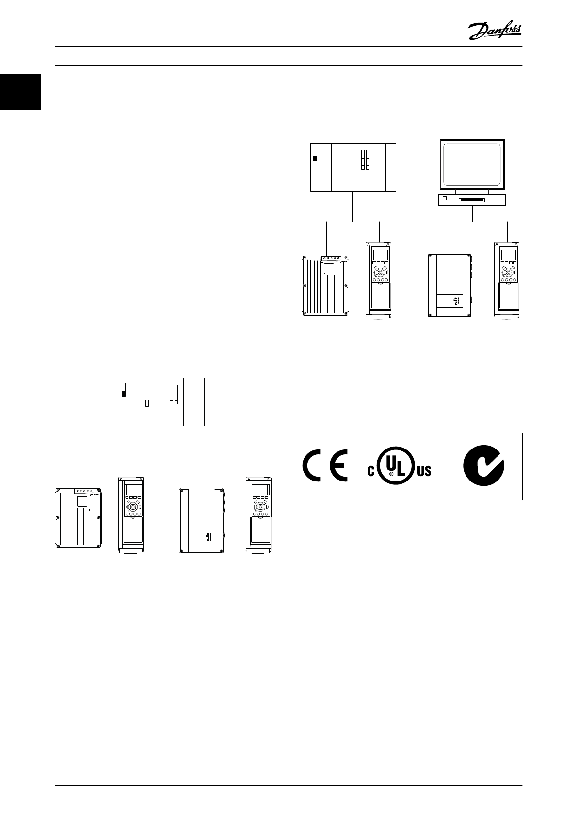
Illustration 1.2 PROFIBUS DP-V1
The PROFIBUS DP extension DP-V1 allows acyclic as well as
cyclic data communication. This feature can be used by a
DP master class 1, for example PLC, as well as a DP master
class 2, for example PC tool.
Illustration 1.1 PROFIBUS DP-V0
Features of a master class 1 connection:
Cyclic data exchange (DP-V0).
•
The acyclic connection is xed and cannot be changed
during operation.
Features of a master class 2 connection:
The acyclic connection can be established (initiated) or
removed (aborted) dynamically even when a master class 1
is active on the network. Use the DP-V1 acyclic connection
Acyclic read/write on parameters.
•
•
•
•
Extended diagnosis.
Initiate/abort acyclic connection.
Acyclic read/write on parameters.
Approvals and Certications
1.5
More approvals and certications are available. For more
information, contact a local Danfoss partner.
4 Danfoss A/S © 01/2016 All rights reserved. MG37G202
Page 7

Introduction Programming Guide
1.6 Symbols, Abbreviations, and
Conventions
CAN Controller area network
CTW Control word
DP Distributed periphery
DTM
DU Data unit
EEPROM Electrical erasable programmable read-only memory
EMC Electromagnetic compatibility
FDT Field device tool
HMI
IND Sub index
LCD Liquid crystal display
LCP Local control panel
LED Light emitting diode
MAV Main actual value
MC1 Master class 1
MC2 Master class 2
MRV Main reference value
OPC
PC Personal computer
PCD Process data
PCA Parameter characteristics
PCV Parameter characteristics value
PDU Protocol data unit
PLC Programmable logic control
PNU Parameter number
PPO Parameter-process data
PVA Parameter value
RC Request/response characteristics
SAP Service access point
SMP Spontaneous message
STW Status word
1 1
Table 1.2 Symbols and Abbreviations
Conventions
Numbered lists indicate procedures.
Bullet lists indicate other information and description of illustrations.
Italicized text indicates:
Cross-reference.
•
Link.
•
Footnote.
•
Parameter name.
•
Parameter group name.
•
Parameter option.
•
* indicates a default setting in a parameter.
MG37G202 Danfoss A/S © 01/2016 All rights reserved. 5
Page 8
Safety
VLT® PROFIBUS DP MCA 101
2 Safety
22
2.1 Safety Symbols
The following symbols are used in this manual:
WARNING
Indicates a potentially hazardous situation that could
result in death or serious injury.
CAUTION
Indicates a potentially hazardous situation that could
result in minor or moderate injury. It can also be used to
alert against unsafe practices.
NOTICE
Indicates important information, including situations that
can result in damage to equipment or property.
2.2 Qualied Personnel
Correct and reliable transport, storage, installation,
operation, and maintenance are required for the troublefree and safe operation of the frequency converter. Only
qualied personnel are allowed to install and operate this
equipment.
Qualied personnel are dened as trained sta, who are
authorized to install, commission, and maintain equipment,
systems, and circuits in accordance with pertinent laws and
regulations. Also, the qualied personnel must be familiar
with the instructions and safety measures described in
these operating instructions.
Safety Precautions
2.3
WARNING
HIGH VOLTAGE
Frequency converters contain high voltage when
connected to AC mains input, DC supply, or load sharing.
Failure to perform installation, start-up, and maintenance
by qualied personnel can result in death or serious
injury.
Only qualied personnel must perform instal-
•
lation, start-up, and maintenance.
WARNING
UNINTENDED START
When the frequency converter is connected to AC mains,
DC supply, or load sharing, the motor may start at any
time. Unintended start during programming, service, or
repair work can result in death, serious injury, or
property damage. The motor can start with an external
switch, a eldbus command, an input reference signal
from the LCP or LOP, via remote operation using MCT 10
Set-up Software, or after a cleared fault condition.
To prevent unintended motor start:
Press [O/Reset] on the LCP before
•
programming parameters.
Disconnect the frequency converter from the
•
mains.
Completely wire and assemble the frequency
•
converter, motor, and any driven equipment
before connecting the frequency converter to
AC mains, DC supply, or load sharing.
WARNING
DISCHARGE TIME
The frequency converter contains DC-link capacitors,
which can remain charged even when the frequency
converter is not powered. High voltage can be present
even when the warning LED indicator lights are o.
Failure to wait the specied time after power has been
removed before performing service or repair work can
result in death or serious injury.
Stop the motor.
•
Disconnect AC mains and remote DC-link power
•
supplies, including battery back-ups, UPS, and
DC-link connections to other frequency
converters.
Disconnect or lock PM motor.
•
Wait for the capacitors to discharge fully. The
•
minimum duration of waiting time is specied
in the chapter Safety in the operating
instructions supplied with the frequency
converter.
Before performing any service or repair work,
•
use an appropriate voltage measuring device to
make sure that the capacitors are fully
discharged.
6 Danfoss A/S © 01/2016 All rights reserved. MG37G202
Page 9

Safety Programming Guide
WARNING
LEAKAGE CURRENT HAZARD
Leakage currents exceed 3.5 mA. Failure to ground the
frequency converter properly can result in death or
serious injury.
Ensure the correct grounding of the equipment
•
by a certied electrical installer.
WARNING
EQUIPMENT HAZARD
Contact with rotating shafts and electrical equipment
can result in death or serious injury.
Ensure that only trained and qualied personnel
•
perform installation, start-up, and maintenance.
Ensure that electrical work conforms to national
•
and local electrical codes.
Follow the procedures in this guide.
•
2 2
CAUTION
INTERNAL FAILURE HAZARD
An internal failure in the frequency converter can result
in serious injury when the frequency converter is not
properly closed.
Ensure that all safety covers are in place and
•
securely fastened before applying power.
MG37G202 Danfoss A/S © 01/2016 All rights reserved. 7
Page 10
130BD878.10
ON
1 2
SW. ver. XX.XX
MS
NS
ON
OFF
Code No. 130B1100
Termination
SN
SW
Address
ON
OFF
S600
S300
LD202 LD200
LD201 LD203
ON ON
8 7 6 5 4 3 2 1
PROFIBUS Option A
1
2
130BB708.10
1
2
4
3
5
Conguration
VLT® PROFIBUS DP MCA 101
3 Conguration
3.1 Congure the PROFIBUS Network
33
Ensure that all PROFIBUS stations connected to the same
bus network have a unique station address.
Select the PROFIBUS address of the frequency converter
via:
Hardware switches.
•
Parameter 9-18 Node Address.
•
The PROFIBUS command SSA (set station
•
address).
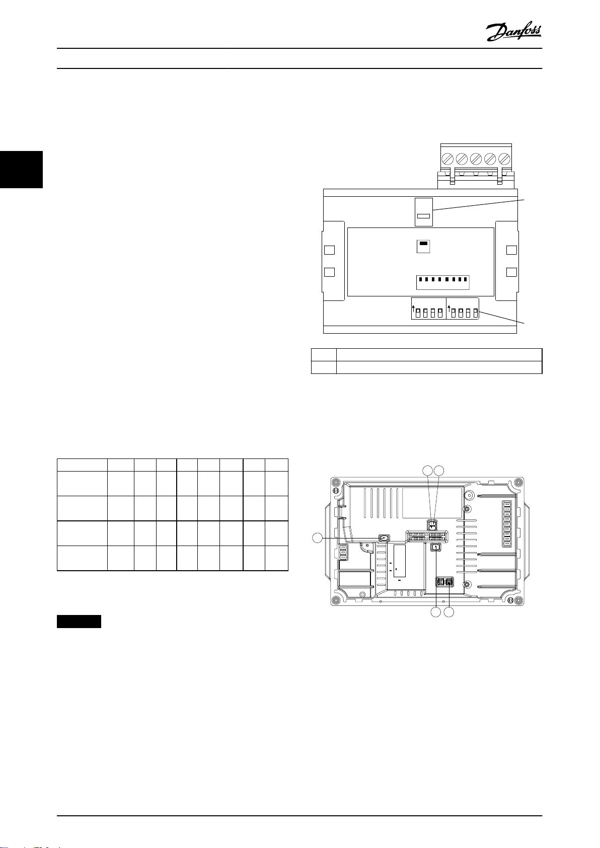
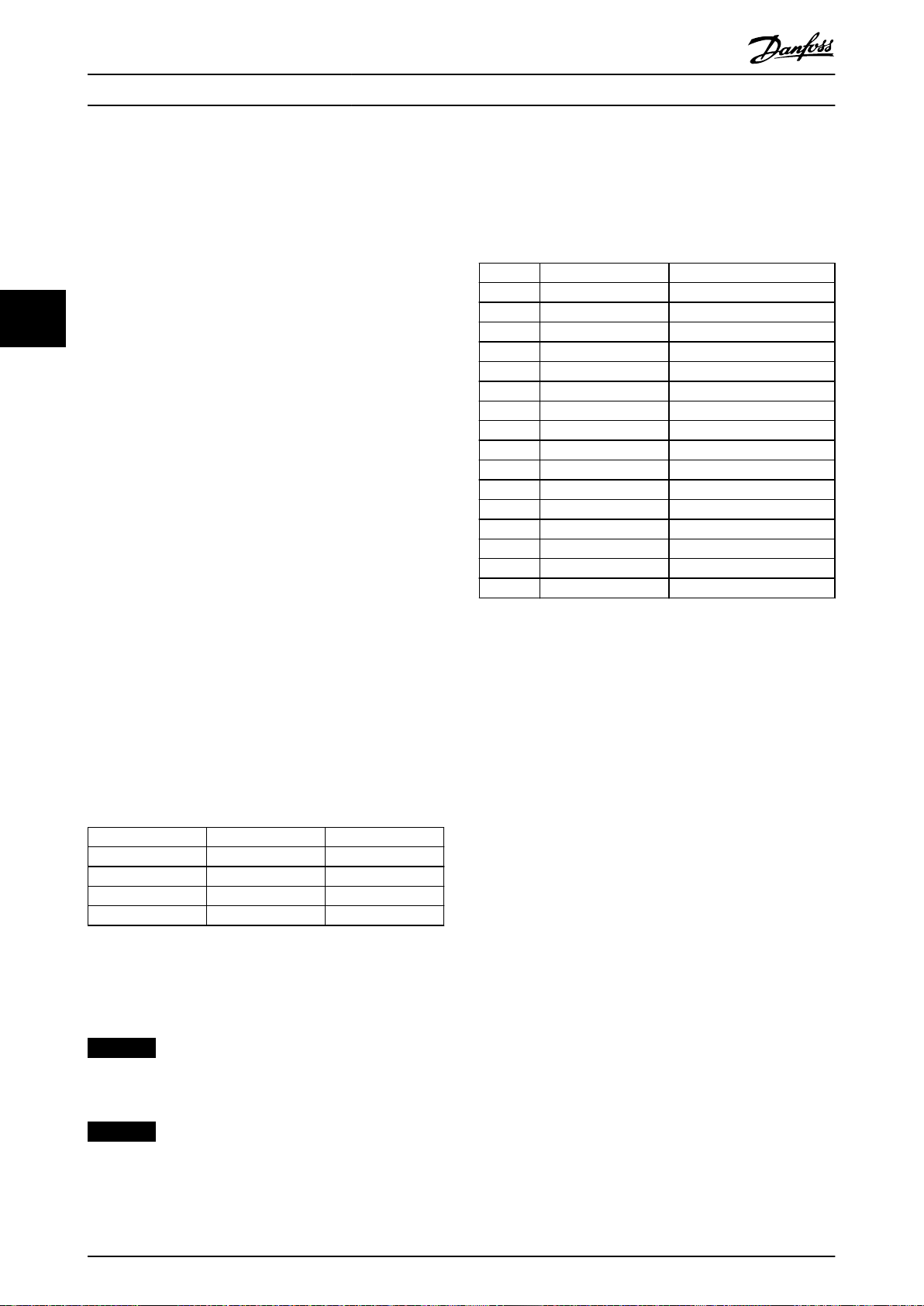
3.1.1 Setting the PROFIBUS Address using
the DIP Switches
To set the PROFIBUS address using the DIP switches:
1. Switch o the supply.
2. Select an address in the range 0–125. Factory
setting is 127.
3. For location of the DIP switches, refer to
Illustration 3.1 and Illustration 3.2.
4. Set the switches according to the address, see
Table 3.1.
1 Termination switch
2 DIP switches
Illustration 3.1 Location and Sequence of the DIP Switches
The DIP switches in the FCD 302 are placed below the
inverter part, see Illustration 3.2.
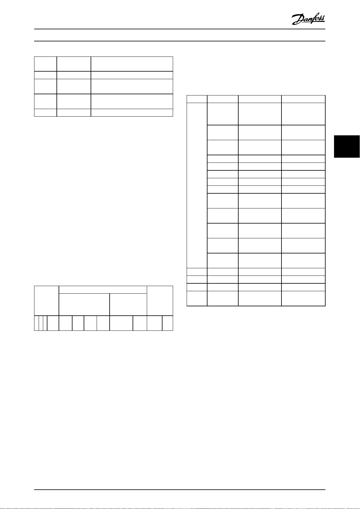
Switch 8 7 6 5 4 3 2 1
Address
value
5 Not
35 Not
82 Not
Table 3.1 Examples: Setting the PROFIBUS Address using the
DIP Switches
NOTICE
Not
+64 +32 +16 +8 +4 +2 +1
used
OFF OFF OFF OFF ON OFF ON
used
OFF ON OFF OFF OFF ON ON
used
ON OFF ON OFF OFF ON OFF
used
Illustration 3.2 FCD 302 Dip Switches
Switch o the supply before changing the DIP switches.
Setting the PROFIBUS address via parameter 9-18 Node
Address
8 Danfoss A/S © 01/2016 All rights reserved. MG37G202
1. Switch o the supply.
2. Set the DIP switch to 126 or 127 (factory switch
setting).
3. Set the address via parameter 9-18 Node Address
or the PROFIBUS SSA-command.
4. The address change comes into eect at the next
power-up.
Page 11
130BC915.10
130BC913.11
Conguration Programming Guide
Setting the PROFIBUS address with set station address
command
1. Switch o the supply.
2. Set the DIP switch to 126 or 127 (factory switch
setting).
3. Set the address via the set station address
command. Use the set station address command
to lock the programmed address and to change
the address. To unlock the address setting,
change parameter 9-18 Node Address or the
address switch, followed by a power cycle. A new
address is eective immediately after applying
the set station address command.
3.2 Congure the Master
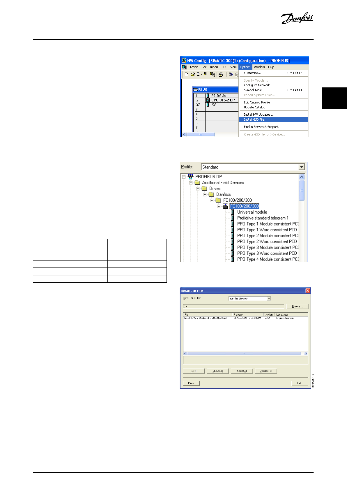
3.2.1 GSD File
To congure a PROFIBUS master, the conguration tool
needs a GSD le for each type of slave on the network.
The GSD le is a PROFIBUS DP standard text le containing
the necessary communications set-up data for a slave.
Download the GSD
converter series vlt-drives.danfoss.com/products/engineering-
software/software-download/eldbus/.
le for the relevant frequency
3 3
Illustration 3.3 Install GSD File
PROFIBUS SW version
(parameter 15-61 Option SW
Version)
1.x da01040A.GSD
2.x da02040A.GSD
FCD 302 da01040B.GSD
Table 3.2 GSD File
The following example shows the procedure of
a PROFIBUS master for FC 301/FC 302, but the procedure is
also valid for other frequency converter series.
1. Import the GSD
2. Import the GSD le to the Simatic Manager
software tool. Import a GSD le once only for
each frequency converter series, following the
initial installation of the software tool. See
Illustration 3.3.
3. Use the browser for the GSD le, install all les,
and import both a GSD le and a bitmap for the
device into the hardware catalog. See
Illustration 3.4 and Illustration 3.5.
le in the conguration tool.
GSD le
conguring
Illustration 3.4 Import a GSD File and a Bitmap
Illustration 3.5 Add a GSD File
MG37G202 Danfoss A/S © 01/2016 All rights reserved. 9
Page 12
130BA564.11
130BC912.11
130BC911.11
Conguration
VLT® PROFIBUS DP MCA 101
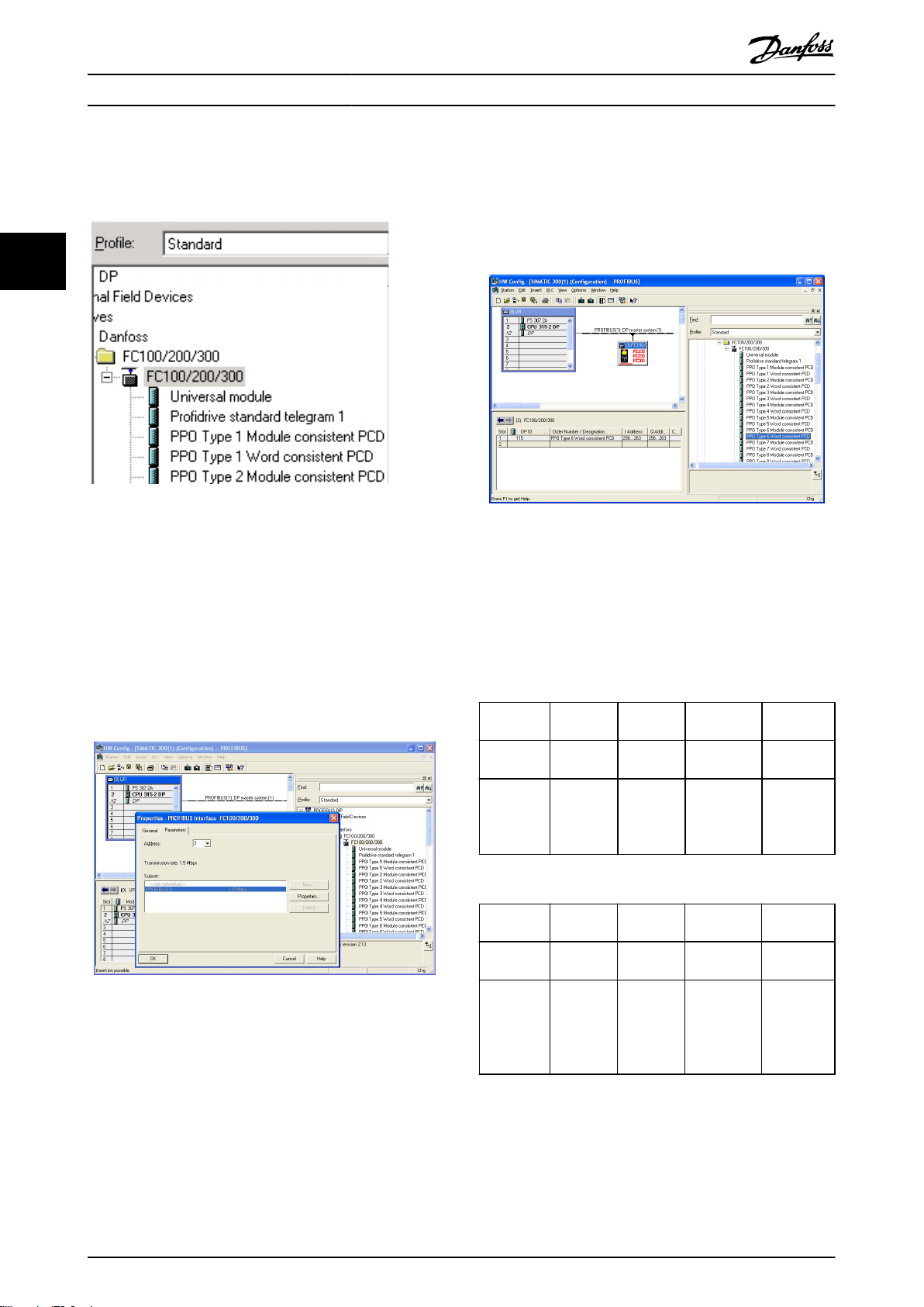
4. Import and access the FC 301/FC 302 GSD le via
the path in the hardware catalog, see
Illustration 3.6.
8. Set up the peripheral input and output data. Data
set up in the peripheral area is transmitted
cyclically via PPO types. Drag and drop a PPO
type 6 word consistent to the rst slot, see
Illustration 3.8. See the PPO types in
chapter 4 Control for more information.
33
Illustration 3.6 Import and Access the GSD File
Illustration 3.8 Drag and Drop PPO Type 6 Word Consistent to
5. Open a project, set up the hardware, and add a
PROFIBUS master system.
6. Select FC 300, then drag and drop it onto the
PROFIBUS in the hardware diagram.
7. A window for the address of the FC 300 appears.
Select the address from the scroll-down list.
Ensure that the address setting matches the
previous address setting in parameter 9-18 Node
Address. See Illustration 3.7.
the First Slot
The conguration tool automatically assigns addresses in
the peripheral address area. In this example, the input and
output areas have the following congurations:
PPO type 6
PCD word
number
Input
address
Set-up STW MAV Parameter 9-
1 2 3 4
256–257 258–259 260–261 262–263
Parameter 9-
16 PCD Read
Congu-
ration.2
16 PCD
Read Cong-
uration.3
Table 3.3 PCD Read (Frequency Converter to PLC)
PCD word
number
Output
address
Illustration 3.7 Select the Address
10 Danfoss A/S © 01/2016 All rights reserved. MG37G202
Set-up CTW MRV Parameter 9-
Table 3.4 PCD Write (PLC to Frequency Converter)
1 2 3 4
256–257 258–259 260–261 262–263
Parameter 9-
15 PCD Write
Congu-
ration.2
15 PCD
Write
Congu-
ration.3
Page 13
130BT322.11
Conguration Programming Guide
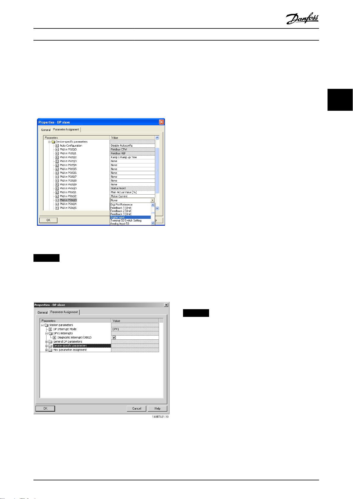
Alternative: For PROFIBUS SW version 2.x and higher, autoconguration of process data is supported. This feature
makes it possible to congure the process data
(parameter 9-15 PCD Write Conguration and
parameter 9-16 PCD Read Conguration) from the PLC/
master. To use auto-conguration, make sure to enable the
feature under DP slave properties. See Illustration 3.9.
Illustration 3.9 Enable Feature under DP Slave Properties
NOTICE
DP-V1 diagnosis is supported for PROFIBUS SW version
2.x and higher. The default setting of the VLT® PROFIBUS
DP MCA 101 is DP-V1 diagnosis. If DP-V0 diagnosis is
required, change the setting under DP slave properties.
Congure the Frequency Converter
3.3
3.3.1 Frequency Converter Parameters
The following parameters are important when conguring
the frequency converter with a PROFIBUS interface:
Parameter 0-40 [Hand on] Key on LCP. Pressing
•
[Hand on] disables control of the frequency
converter via PROFIBUS.
Parameter 8-02 Control Word Source. After an
•
initial power-up, the frequency converter
automatically detects whether a eldbus option is
installed in slot A. The frequency converter then
sets parameter 8-02 Control Word Source to [3]
Option A. If an option is added to, changed in, or
removed from an already commissioned
frequency converter, it does not change
parameter 8-02 Control Word Source. Instead, the
frequency converter enters trip mode and shows
an error.
Parameter 8-10 Control Word Prole. Select
•
between the Danfoss FC Prole and the
PROFIdrive prole.
Parameter 8-50 Coasting Select to
•
parameter 8-56 Preset Reference Select. Select how
to gate PROFIBUS control commands with digital
input command of the control card.
Parameter 8-03 Control Word Timeout Time to
•
parameter 8-05 End-of-Timeout Function. Set the
reaction in the event of a bus timeout via these
parameters.
Parameter 9-18 Node Address.
•
Parameter 8-07 Diagnosis Trigger.
•
3 3
NOTICE
The setting in parameter 8-01 Control Site overrides the
settings in parameter 8-50 Coasting Select to
parameter 8-56 Preset Reference Select, and they all act on
bus control.
Illustration 3.10 DP-V1 Diagnosis
Download the conguration le to the PLC. The PROFIBUS
system is able to go online, and it starts to exchange data
when the PLC is set to run mode.
MG37G202 Danfoss A/S © 01/2016 All rights reserved. 11
Page 14
A
130BC259.10
Conguration
VLT® PROFIBUS DP MCA 101
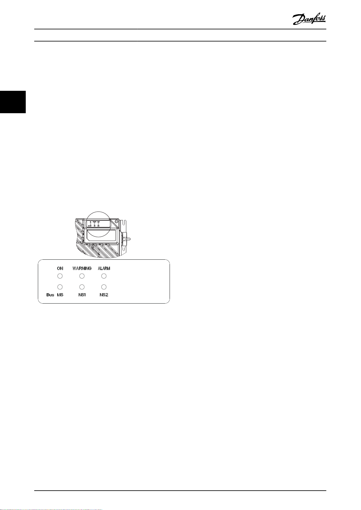
3.3.2 LEDs
The 2 bicolor LEDs in the VLT® PROFIBUS DP MCA 101
indicate the status of PROFIBUS communication.
33
The LED marked NS (FCD 302: NS2) indicates the network
status, that is, the cyclic communication to the PROFIBUS
master. When this light is a constant green, data exchange
between the master and the frequency converter is active.
The LED marked MS (FCD 302: BUS MS) indicates the
module status, that is, acyclic DP-V1 communication from
either a PROFIBUS master class 1 (PLC) or a master class 2
(MCT 10 Set-up Software, FDT tool). When this light is a
constant green, DP-V1 communication from master classes
1 and 2 is active.
For details of the full range of communications status
indicated by the LEDs, refer to chapter 8 Troubleshooting.
Illustration 3.11 FCD 302 LED Panel
12 Danfoss A/S © 01/2016 All rights reserved. MG37G202
Page 15

Control Programming Guide
4 Control
4.1 PPO Types
The PROFIBUS prole for frequency converters species a
number of communication objects (parameter process data
objects, PPO). The PROFIBUS prole for frequency
converters is suitable for data exchange between a process
controller (for example PLC) and a frequency converter. All
PPOs are dened for cyclic data transfer (DP-V0) for
transferring process data (PCD) and parameters (PCA) from
the master to the slave, and conversely.
Pure process data objects
PPO types 3, 4, 6, 7, and 8 are pure process data objects
for applications requiring no cyclic parameter access. The
PLC sends out process control data, and the frequency
converter then responds with a PPO of the same length,
containing process status data.
Illustration 4.1 shows the available PPO types:
PCD 1: The
•
(PCD 1) comprise a xed part present in all PPO
types.
PCD 2: The next 2 bytes are
•
entries (see parameter 9-15 PCD Write Congu-
ration [1]), but congurable for PCD read entries
(see parameter 9-16 PCD Read Conguration [1]).
PCD 3–10: In the remaining bytes, the process
•
data can be parameterized with process signals,
see parameter 9-23 Parameters for Signals.
The setting in parameter 9-15 PCD Write Conguration
determines the signals for transmission (request) from the
master to the frequency converter.
rst 2 bytes of the process data area
xed for PCD write
The setting in parameter 9-16 PCD Read Conguration
determines the signals for transmission (response) from the
frequency converter to the master.
Parameter channel and process data
PPO types 1, 2, and 5 consist of a parameter channel and
process data. Use the parameter channel for reading
and/or updating of parameters (successively). Alternatively,
for better utilization of I/O and PLC capacity, access
parameters via DP-V1. To access via DP-V1, select a pure
process data object (PPO type 3, 4, 6, 7, or 8).
Select the PPO type in the master conguration. The
selection is automatically recorded in the frequency
converter. No manual setting of PPO types in the
frequency converter is required. Read the current PPO type
in parameter 9-22 Telegram Selection. The setting [1]
Standard telegram 1 is equivalent to PPO type 3.
In addition, all PPO types can be set up as word-consistent
or module-consistent. The process data area can be wordor module-consistent, whereas the parameter channel
must always be module-consistent.
Word-consistent data is transmitted as individual,
•
independent words between the PLC and the
frequency converter.
Module-consistent data is transmitted as sets of
•
interrelated words transferred simultaneously
between the PLC and the frequency converter.
4 4
MG37G202 Danfoss A/S © 01/2016 All rights reserved. 13
Page 16
CTW/STW
REF/MAV
PCD 2
Read/
Write
PCD 3
Read/
Write
Standard telegram
1
PCD 4
Read/
Write
PCD 5
Read/
Write
PPO 4
PPO 6
PPO 7
PPO 8
Danfoss telegram
(The old PPO type 3)
PCV
CTW/STW REF/MAV
PCD 2
Read/
Write
PCD 3
Read/
Write
PCD 4
Read/
Write
PCD 5
Read/
Write
CTW/STW
REF/MAV
PCD 2
Read/
Write
PCD 3
Read/
Write
PCD 4
Read/
Write
PCD 5
Read/
Write
PCD 6
Read/
Write
PCD 7
Read/
Write
PCD 8
Read/
Write
PCD 9
Read/
Write
CTW/STW REF/MAV
PCD 2
Read/
Write
PCD 3
Read/
Write
PCD 4
Read/
Write
PCD 5
Read/
Write
PCD 6
Read/
Write
PCD 7
Read/
Write
CTW/STW REF/MAV
CTW/STW REF/MAV
PPO 3
CTW/STW REF/MAV
PCD 2
Read/
Write
PCD 3
Read/
Write
PPO 2
PCV
CTW/STW
REF/MAV
PPO 1
PCV
130BD911.10
Control
VLT® PROFIBUS DP MCA 101
44
Illustration 4.1 Available PPO Types
14 Danfoss A/S © 01/2016 All rights reserved. MG37G202
Page 17
Control Programming Guide
4.2 Process Data
Use the process data part of the PPO to control and
monitor the frequency converter via the PROFIBUS.
4.2.1 Process Control Data
Process control data (PCD) is the process data sent from
the PLC to the frequency converter.
Master/slave
1 2 3 ....... 10
CTW MRV PCD ....... PCD
PCD write
Table 4.1 Process Control Data
PCD 1 contains a 16-bit control word, and each bit controls
specic function of the frequency converter, see
a
chapter 4.3 Control Prole.
PCD 2 contains a 16-bit speed setpoint in percentage
format. See chapter 4.2.3 Reference Handling.
The settings in parameter 9-15 PCD Write Conguration and
parameter 9-16 PCD Read Conguration dene the content
of PCD 3 to PCD 10.
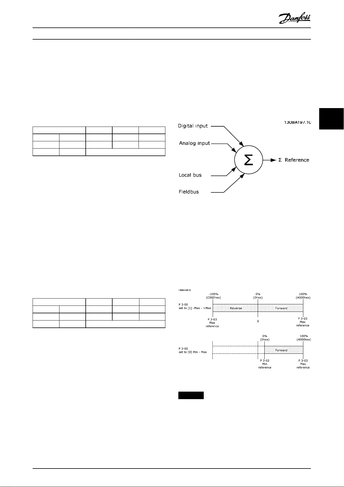
4.2.3 Reference Handling
The reference handling is an advanced mechanism that
sums up references from dierent sources, as shown in
Illustration 4.2.
For more information on reference handling, refer to the
design guide of the relevant frequency converter.
4 4
Illustration 4.2 Reference
The reference, or speed setpoint, is sent via PROFIBUS and
is always transmitted to the frequency converter in
percentage format as integers shown in hexadecimal (0–
4000 hex).
4.2.2 Process Status Data
Process status data is the process data sent from the
frequency converter and contains information about the
current state.
Slave/master
1 2 3 ...... 10
STW MAV PCD ...... PCD
PCD read
Table 4.2 Process Status Data
PCD 1 contains a 16-bit status word, and each bit contains
information regarding a possible state of the frequency
converter.
PCD 2 contains per default the value of the current speed
of the frequency converter in percentage format (see
chapter 4.2.3 Reference Handling). PCD 2 can be congured
to contain other process signals.
The settings in parameter 9-16 PCD Read Conguration
dene the content of PCD 3 to PCD 10.
The reference (MRV) and feedback (MAV) are always scaled
equally. The setting of parameter 3-00 Reference Range
determines the scaling of the reference and feedback
(MAV), see Illustration 4.3.
Illustration 4.3 Reference (MRV) and Feedback (MAV), Scaled
NOTICE
When parameter 3-00 Reference Range is set to [0] Min Max, a negative reference is handled as 0%.
The actual output of the frequency converter is limited by
the speed limit parameters Motor Low/High Speed Limit
[RPM/Hz] in parameter 4-11 Motor Speed Low Limit [RPM] to
parameter 4-14 Motor Speed High Limit [Hz].
MG37G202 Danfoss A/S © 01/2016 All rights reserved. 15
Page 18
Control
VLT® PROFIBUS DP MCA 101
The nal speed limit is set in parameter 4-19 Max Output
Frequency.
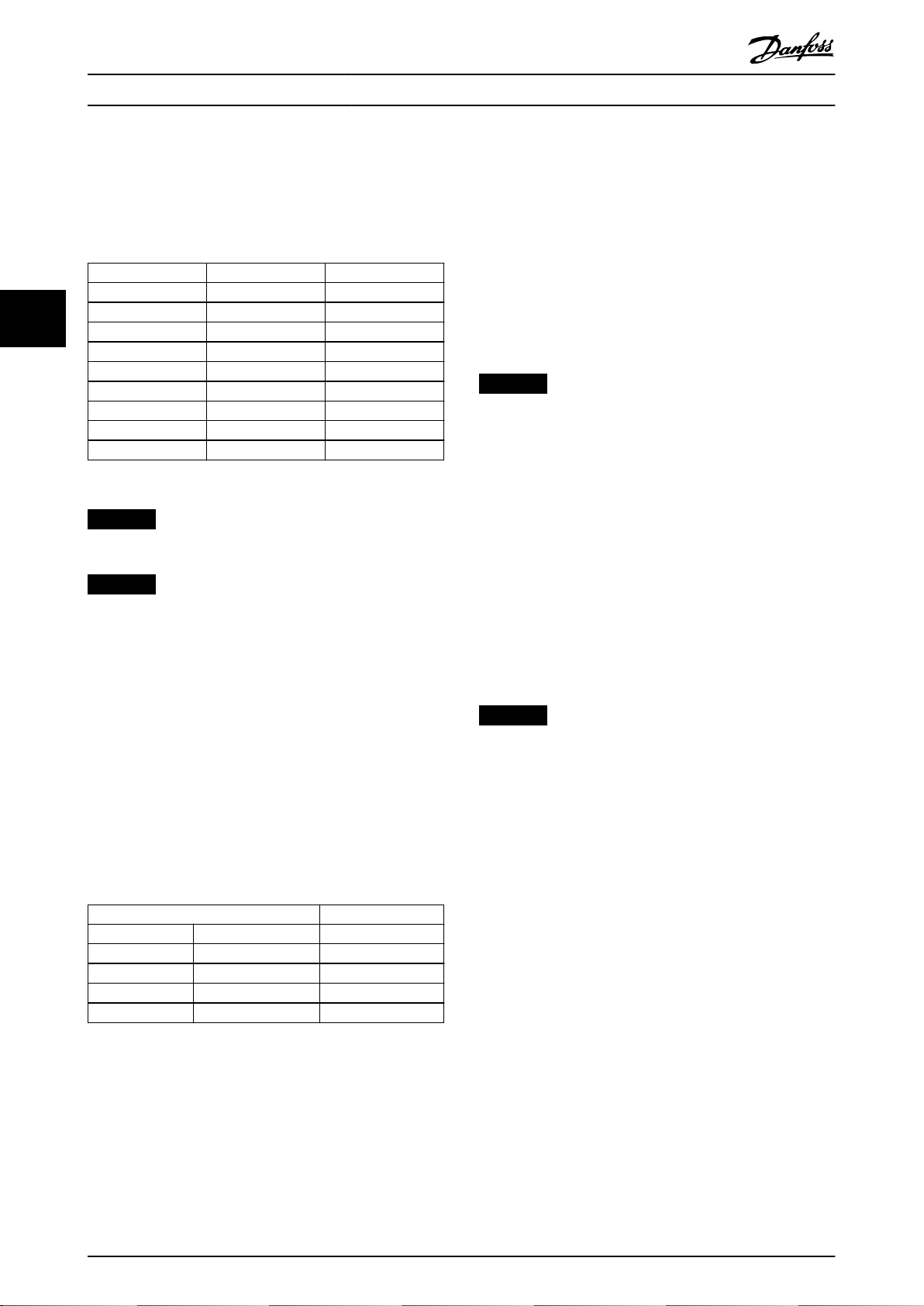
Table 4.3 lists the reference (MRV) and the feedback (MAV)
formats.
MRV is the process setpoint.
•
MAV expresses the actual process feedback (range
•
±200%).
4.2.5 Inuence of the Digital Input
MRV/MAV Integer in hex Integer in decimal
100% 4000 16384
44
75% 3000 12288
50% 2000 8192
25% 1000 4096
0% 0 0
-25% F000 -4096
-50% E000 -8192
-75% D000 -12288
-100% C000 -16384
Table 4.3 Reference/Feedback (MRV/MAV) Format
NOTICE
Negative numbers are formed as complement of 2.
NOTICE
The data type for MRV and MAV is an N2 16-bit
standardized value, expressing a range from -200% to
+200% (8001 to 7FFF).
Example
The following settings determine the speed, as shown in
Table 4.4:
Parameter 1-00 Conguration Mode set to [0]
•
Speed open loop.
Parameter 3-00 Reference Range set to [0] Min-Max.
•
Parameter 3-02 Minimum Reference set to 100
•
RPM.
Parameter 3-03 Maximum Reference set to 3000
•
RPM.
Terminals on FC Control Mode
In parameter 8-50 Coasting Select to parameter 8-56 Preset
Reference Select, set the inuence of the digital input
terminals on the control of the frequency converter.
NOTICE
The setting of parameter 8-01 Control Site overrules the
settings in parameter 8-50 Coasting Select to
parameter 8-56 Preset Reference Select. The setting of
terminal 37 coast stop (safe) overrules any other
parameter.
Program each of the digital input signals to logic AND,
logic OR, or to have no relation to the corresponding bit in
the control word. In this way, the following signal sources
initiate a specic control command, for example stop/
coast:
Fieldbus only.
•
Fieldbus AND digital input.
•
Either eldbus OR digital input terminal.
•
NOTICE
To control the frequency converter via PROFIBUS, set
parameter 8-50 Coasting Select to either [1] Bus or [2]
Logic AND. Then set parameter 8-01 Control Site to [0]
Digital and ctrl.word or [2] Controlword only.
For more detailed information and examples of logical
relationship options, see chapter 8 Troubleshooting.
Control Prole
4.3
MRV/MAV Actual speed [RPM]
0% 0 hex 100
25% 1000 hex 825
50% 2000 hex 1550
75% 3000 hex 2275
100% 4000 hex 3000
Table 4.4 Actual Speed for MRV/MAV
Control the frequency converter according to:
The PROFIdrive prole, see chapter 4.4 PROFIdrive
•
Control Prole, or
The Danfoss FC control, see chapter 4.5 Danfoss
•
FC Control Prole.
Select the control prole in parameter 8-10 Control Word
Prole. The choice of prole aects the control word and
status word only.
4.2.4 Process Control Operation
Chapter 4.4 PROFIdrive Control Prole and
In process control operation, parameter 1-00 Conguration
Mode is set to [3] Process.
The reference range in parameter 3-00 Reference Range is
always [0] Min - Max.
16 Danfoss A/S © 01/2016 All rights reserved. MG37G202
chapter 4.5 Danfoss FC Control Prole provide a detailed
description of control and status data.
Page 19
Control Programming Guide
4.4 PROFIdrive Control Prole
This section describes the functionality of the control word
and status word in the PROFIdrive prole.
4.4.1 Control Word According to
PROFIdrive Prole (CTW)
The control word is used to send commands from a master
(for example a PC) to a slave.
Bit Bit=0 Bit=1
00 OFF 1 ON 1
01 OFF 2 ON 2
02 OFF 3 ON 3
03 Coasting No coasting
04 Quick stop Ramp
05 Hold frequency output Use ramp
06 Ramp stop Start
07 No function Reset
08 Jog 1 OFF Jog 1 ON
09 Jog 2 OFF Jog 2 ON
10 Data invalid Data valid
11 No function Slow down
12 No function Catch up
13 Parameter set-up Selection lsb
14 Parameter set-up Selection msb
15 No function Reverse
Table 4.5 Control Word Bits
Explanation of the control bits
Bit 00, OFF 1/ON 1
Normal ramp stops using the ramp times of the actual
selected ramp.
Bit 00=0 stops and activates the output relay 1 or 2 if the
output frequency is 0 Hz, and if [31] Relay 123 is selected
in parameter 5-40 Function Relay.
When bit 0=1, the frequency converter is in state 1,
Switching on inhibited.
Refer to Illustration 4.4.
Bit 01, OFF 2/ON 2
Coast stop.
Bit 01=0 coast stops and activates the output relay 1 or 2
if the output frequency is 0 Hz, and if [31] Relay 123 is
selected in parameter 5-40 Function Relay.
When bit 01=1, the frequency converter is in state 1,
Switching on inhibited. Refer to Illustration 4.4.
Bit 02, OFF 3/ON 3
Quick stop using the ramp time of parameter 3-81 Quick
Stop Ramp Time.
Bit 02=0 quick stops and activates the output relay 1 or 2
if the output frequency is 0 Hz, and if [31] Relay 123 is
selected in parameter 5-40 Function Relay.
When bit 02=1, the frequency converter is in state 1,
Switching on inhibited.
Refer to Illustration 4.4.
Bit 03, coasting/no coasting
Bit 03=0 leads to a coast stop.
When bit 03=1, if the other start conditions are fullled,
the frequency converter can start.
NOTICE
The selection in parameter 8-50 Coasting Select
determines how bit 03 is linked with the corresponding
function of the digital inputs.
Bit 04, quick stop/ramp
Quick stop using the ramp time of parameter 3-81 Quick
Stop Ramp Time.
When bit 04=0, a quick stop occurs.
When bit 04=1, if the other start conditions are fullled,
the frequency converter can start.
NOTICE
The selection in parameter 8-51 Quick Stop Select
determines how bit 04 is linked with the corresponding
function of the digital inputs.
Bit 05, hold frequency output/use ramp
When bit 05=0, the present output frequency is
maintained, even if the reference value is modied.
When bit 05=1, the frequency converter can perform its
regulating function again according to the respective
reference value.
Bit 06, ramp stop/start
Normal ramp stop using the ramp times of the actual
ramp selected. In addition, if [31] Relay 123 is selected in
parameter 5-40 Function Relay, and if the output frequency
is 0 Hz, this bit activates output relay 01 or 04.
Bit 06=0 stops the frequency converter.
When bit 06=1, if the other start conditions are fullled,
the frequency converter can start.
NOTICE
The selection in parameter 8-53 Start Select determines
how bit 06 is linked with the corresponding function of
the digital inputs.
Bit 07, no function/reset
Reset after switching o. Acknowledges event in fault
buer.
When bit 07=0, no reset occurs.
When there is a slope change of bit 07 to 1, a reset occurs
after switching o.
Bit 08, jog 1 OFF/ON
Activation of the pre-programmed speed in
parameter 8-90 Bus Jog 1 Speed. JOG 1 is only possible if bit
04=0 and bits 00–03=1.
Bit 09, jog 2 OFF/ON
Activation of the pre-programmed speed in
parameter 8-91 Bus Jog 2 Speed. JOG 2 is only possible if bit
04=0 and bits 00–03=1.
4 4
MG37G202 Danfoss A/S © 01/2016 All rights reserved. 17
Page 20
Control
VLT® PROFIBUS DP MCA 101
Bit 10, data invalid/valid
Tells the frequency converter whether to use or ignore the
control word.
Bit 10=0 ignores the control word, making it possible to
turn o the control word when updating/reading
parameters.
Bit 10=1 uses the control word. This function is relevant,
because the control word is always contained in the
telegram, regardless of which type of telegram is used.
44
Bit 11, no function/slow down
Used to reduce the speed reference value by the amount
given in parameter 3-12 Catch up/slow Down Value.
When bit 11=0, no modication of the reference value
occurs.
When bit 11=1, the reference value is reduced.
Bit 12, no function/catch up
Used to increase the speed reference value by the amount
given in parameter 3-12 Catch up/slow Down Value.
When bit 12=0, no modication of the reference value
occurs.
When bit 12=1, the reference value is increased.
If both slowing down and accelerating are activated (bits
11 and 12=1), slowing down has priority, and the speed
reference value is reduced.
Bits 13/14, set-up selection
Bits 13 and 14 are used to select between the 4 parameter
set-ups according to Table 4.6.
The function is only possible if [9] Multi Set-up has been
selected in parameter 0-10 Active Set-up. The selection in
parameter 8-55 Set-up Select determines how bits 13 and
14 are linked with the corresponding function of the
digital inputs. Changing set-up while running is only
possible if the set-ups have been linked in
parameter 0-12 This Set-up Linked to.
Set-up Bit 13 Bit 14
1 0 0
2 1 0
3 0 1
4 1 1
Table 4.6 Parameter Set-ups
Bit 15, no function/reverse
Bit 15=0 causes no reversing.
Bit 15=1 causes reversing.
NOTICE
In the factory setting, reversing is set to [0] Digital in
parameter 8-54 Reversing Select.
NOTICE
Bit 15 causes reversing only when Ser. communication,
Logic or, or Logic and is selected.
4.4.2 Status Word According to PROFIdrive
Prole (STW)
The status word is used to notify a master (for example a
PC) about the status of a slave.
Bit Bit=0 Bit=1
00 Control not ready Control ready
01 Drive not ready Drive ready
02 Coasting Enable
03 No error Trip
04 OFF 2 ON 2
05 OFF 3 ON 3
06 Start possible Start not possible
07 No warning Warning
08
09 Local operation Bus control
10 Out of frequency limit Frequency limit ok
11 No operation In operation
12 Drive OK Stopped, auto start
13 Voltage OK Voltage exceeded
14 Torque OK Torque exceeded
15 Timer OK Timer exceeded
Table 4.7 Status Word Bits
Explanation of the status bits
Bit 00, control not ready/ready
When bit 00=0, bit 00, 01, or 02 of the control word is 0
(OFF 1, OFF 2, or OFF 3) - or the frequency converter is
switched
When bit 00=1, the frequency converter control is ready,
but power is not necessarily supplied to the unit (in the
event of 24 V external supply of the control system).
Bit 01, VLT not ready/ready
Same signicance as bit 00, however, power is supplied to
the unit. The frequency converter is ready when it receives
the necessary start signals.
Bit 02, coasting/enable
When bit 02=0, bit 00, 01, or 02 of the control word is 0
(OFF 1, OFF 2, or OFF 3 or coasting) - or the frequency
converter is switched o (trip).
When bit 02=1, bit 00, 01, or 02 of the control word is 1,
and the frequency converter has not tripped.
Bit 03, no error/trip
When bit 03=0, no error condition exists in the frequency
converter.
When bit 03=1, the frequency converter has tripped and
requires a reset signal before it can start.
Bit 04, ON 2/OFF 2
When bit 01 of the control word is 0, bit 04=0.
When bit 01 of the control word is 1, bit 04=1.
Bit 05, ON 3/OFF 3
When bit 02 of the control word is 0, bit 05=0.
When bit 02 of the control word is 1, bit 05=1.
Speed ≠ reference
o (tripped).
Speed = reference
18 Danfoss A/S © 01/2016 All rights reserved. MG37G202
Page 21

Control Programming Guide
Bit 06, start possible/start not possible
If [1] PROFIdrive has been selected in
parameter 8-10 Control Word Prole, bit 06 is 1 after a
switch-o acknowledgement, after activation of OFF2 or
OFF3, and after switching on the mains voltage. To reset
Start not possible, set bit 00 of the control word to 0, and
bits 01, 02, and 10 to 1.
Bit 07, no warning/warning
Bit 07=0 means that there are no warnings.
Bit 07=1 means that a warning has occurred.
Bit 08, speed≠reference/speed=reference
When bit 08=0, the current speed of the motor deviates
from the set speed reference value. The deviation may
occur, for example, when the speed is being changed
during start/stop through ramp up/down.
When bit 08=1, the current speed of the motor
corresponds to the set speed reference value.
Bit 09, local operation/bus control
Bit 09=0 indicates that the frequency converter has been
stopped with [Stop] on the LCP, or that [0] Linked to hand
or [2] Local has been selected in parameter 3-13 Reference
Site.
When bit 09=1, the frequency converter can be controlled
through the serial interface.
Bit 10, out of frequency limit/frequency limit OK
When bit 10=0, the output frequency is outside the limits
set in parameter 4-52 Warning Speed Low and
parameter 4-53 Warning Speed High.
When bit 10=1, the output frequency is within the
indicated limits.
Bit 11, no operation/operation
When bit 11=0, the motor does not turn.
When bit 11=1, the frequency converter has a start signal,
or the output frequency is higher than 0 Hz.
Bit 12, drive OK/stopped, auto start
When bit 12=0, there is no temporary overload of the
inverter.
When bit 12=1, the frequency converter has stopped due
to overload. However, the frequency converter has not
switched o (tripped) and starts again after the overload
has ended.
Bit 13, voltage OK/voltage exceeded
When bit 13=0, the voltage limits of the frequency
converter are not exceeded.
When bit 13=1, the direct voltage in the DC link of the
frequency converter is too low or too high.
Bit 14, torque OK/torque exceeded
When bit 14=0, the motor torque is below the limit
selected in parameter 4-16 Torque Limit Motor Mode and
parameter 4-17 Torque Limit Generator Mode.
When bit 14=1, the limit selected in parameter 4-16 Torque
Limit Motor Mode or parameter 4-17 Torque Limit Generator
Mode is exceeded.
Bit 15, timer OK/timer exceeded
When bit 15=0, the timers for the motor thermal
protection and thermal frequency converter protection
have not exceeded 100%.
When bit 15=1, a timer has exceeded 100%.
4 4
MG37G202 Danfoss A/S © 01/2016 All rights reserved. 19
Page 22

130BD806.10
Control
VLT® PROFIBUS DP MCA 101
4.4.3 PROFIdrive State Transition Diagram
In the PROFIdrive control prole, the control bits:
0–3 perform the basic start-up/power-down functions.
•
4–15 perform application-oriented control.
•
Illustration 4.4 shows the basic state transition diagram, where control bits 0–3 control the transitions, and the corresponding
status bit indicates the actual state. The black bullets indicate the priority of the control signals, where fewer bullets indicate
44
lower priority, and more bullets indicate higher priority.
Illustration 4.4 PROFIdrive State Transition Diagram
20 Danfoss A/S © 01/2016 All rights reserved. MG37G202
Page 23

Control Programming Guide
4.5 Danfoss FC Control Prole
4.5.1 Control Word According to FC Prole
(CTW)
To select Danfoss FC protocol in the control word, set
parameter 8-10 Control Word Prole to [0] Frequency
converter prole. Use the control word to send commands
from a master (PLC or PC) to a slave (frequency converter).
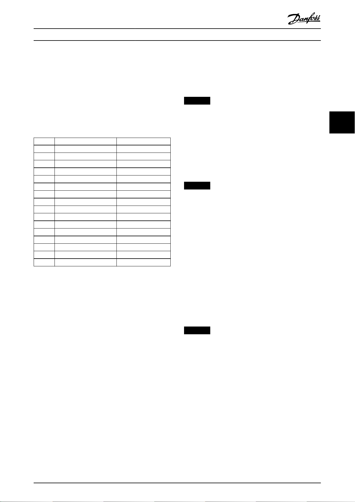
Bit Bit value=0 Bit value=1
00 Reference value External selection lsb
01 Reference value External selection msb
02 DC brake Ramp
03 Coasting No coasting
04 Quick stop Ramp
05 Hold output frequency Use ramp
06 Ramp stop Start
07 No function Reset
08 No function Jog
09 Ramp 1 Ramp 2
10 Data invalid Data valid
11 No function Relay 01 active
12 No function Relay 04 active
13 Parameter set-up Selection lsb
14 Parameter set-up Selection msb
15 No function Reverse
Table 4.8 Bit Values for FC Control Word
Explanation of the control bits
Bits 00/01 reference value
Use bits 00 and 01 to select between the 4 reference
values, which are pre-programmed in parameter 3-10 Preset
Reference according to Table 4.9.
NOTICE
In parameter 8-56 Preset Reference Select, a selection is
made to dene how bit 00/01 gates with the
corresponding function on the digital inputs.
Bit 01 Bit 00 Programmed
reference value
0 0 1 [0]
0 1 2 [1]
1 0 3 [2]
1 1 4 [3]
Table 4.9 Programmed Reference Values for Bits
Parameter
Parameter 3-10 Preset
Reference
Parameter 3-10 Preset
Reference
Parameter 3-10 Preset
Reference
Parameter 3-10 Preset
Reference
Bit 02, DC brake
Bit 02=0 leads to DC braking and stop. Braking current and
duration are set in parameter 2-01 DC Brake Current and
parameter 2-02 DC Braking Time.
Bit 02=1 leads to ramping.
Bit 03, coasting
Bit 03=0 causes the frequency converter immediately to
coast the motor to a standstill.
Bit 03=1 enables the frequency converter to start the
motor if the other starting conditions have been fullled.
NOTICE
In parameter 8-50 Coasting Select, a selection is made to
dene how bit 03 gates with the corresponding function
on a digital input.
Bit 04, quick stop
Bit 04=0 quick stops the frequency converter and ramps
the motor speed down to stop via parameter 3-81 Quick
Stop Ramp Time.
Bit 04=1 makes the frequency converter ramp the motor
speed down to stop via parameter 3-42 Ramp 1 Ramp
Down Time or parameter 3-52 Ramp 2 Ramp Down Time.
Bit 05, hold output frequency
Bit 05=0 freezes the present output frequency (in Hz). The
frozen output frequency can only be changed with the
digital inputs (parameter 5-10 Terminal 18 Digital Input to
parameter 5-15 Terminal 33 Digital Input) programmed to
[21] Speed up and [22] Speed down.
Bit 05=1 uses ramp.
4 4
MG37G202 Danfoss A/S © 01/2016 All rights reserved. 21
Page 24

Control
VLT® PROFIBUS DP MCA 101
NOTICE
If freeze output is active, stop the frequency converter
with
Bit 03 coast stop.
•
Bit 02 DC brake.
•
Digital input (parameter 5-10 Terminal 18 Digital
•
Input to parameter 5-15 Terminal 33 Digital
44
Bit 06, ramp stop/start
Bit 06=0 stops the frequency converter and the motor
speed ramps down to stop via the selected ramp-down
parameter.
Bit 06=1 allows the frequency converter to start the motor
if the other starting conditions have been fullled.
Input) programmed to DC braking, coasting stop,
or reset and coasting stop.
Bit 13/14, selection of set-up
Use bits 13 and 14 to select from the 4 menu set-ups
according to Table 4.10:
The function is only possible when [9] Multi Set-ups is
selected in parameter 0-10 Active Set-up.
Set-up Bit 14 Bit 13
1 0 0
2 0 1
3 1 0
4 1 1
Table 4.10 Set-up selection
NOTICE
In parameter 8-55 Set-up Select, dene how bit 13/14
gates with the corresponding function on the digital
inputs.
NOTICE
In parameter 8-53 Start Select, dene how bit 06 ramp
stop/start gates with the corresponding function on a
digital input.
Bit 07, reset
Bit 07=0 does not cause a reset.
Bit 07=1 resets a trip. Reset is activated on the signal’s
leading edge, that is, when changing from logic 0 to logic
1.
Bit 08, jog
Bit 08=0, no function.
Bit 08=1, parameter 3-19 Jog Speed [RPM] determines the
output frequency.
Bit 09, selection of ramp 1/2
Bit 09=0, ramp 1 is active (parameter 3-40 Ramp 1 Type to
parameter 3-47 Ramp 1 S-ramp Ratio at Decel. Start).
Bit 09=1, ramp 2 is active (parameter 3-50 Ramp 2 Type to
parameter 3-57 Ramp 2 S-ramp Ratio at Decel. Start).
Bit 10, data not valid/data valid
Tells the frequency converter to use or ignore the control
word.
Bit 10=0 ignores the control word.
Bit 10=1 uses the control word. This function is relevant,
because the control word is always contained in the
telegram, regardless of which type of telegram is used.
Thus, it is possible to turn o the control word, if it is not
needed when updating or reading parameters.
Bit 11, relay 01
Bit 11=0, relay 01 is not activated.
Bit 11=1, relay 01 is activated, provided control word bit 11
is selected in parameter 5-40 Function Relay.
Bit 12, relay 04
Bit 12=0, relay 04 is not activated.
Bit 12=1, relay 04 is activated, provided [37] Control word
bit 12 is selected in parameter 5-40 Function Relay.
Bit 15 reverse
Bit 15=0 means no reversing.
Bit 15=1 means reversing.
4.5.2 Status Word According to FC Prole
(STW)
The status word is used to inform the master (for example
a PC) of the operating mode of the slave (frequency
converter).
Refer to chapter 7 Application Examples for an example of a
status word telegram using PPO type 3.
Bit Bit=0 Bit=1
00 Control not ready Control ready
01 Frequency converter not
ready
02 Coasting Enable
03 No error Trip
04 No error Error (no trip)
05 Reserved –
06 No error Trip lock
07 No warning Warning
08 Speed reference Speed=reference
09 Local operation Bus control
10 Out of frequency limit Frequency limit ok
11 No operation In operation
12 Frequency converter OK Stopped, auto start
13 Voltage OK Voltage exceeded
14 Torque OK Torque exceeded
15 Timer OK Timer exceeded
Table 4.11 Denition of Status Bits
Frequency converter ready
22 Danfoss A/S © 01/2016 All rights reserved. MG37G202
Page 25

Control Programming Guide
Explanation of the status bits
Bit 00, control not ready/ready
Bit 00=0, the frequency converter has tripped.
Bit 00=1, the frequency converter controls are ready, but
the power component is not necessarily receiving any
power (in case of 24 V external supply to controls).
Bit 01, frequency converter ready
Bit 01=0, the frequency converter is not ready for
operation.
Bit 01=1, the frequency converter is ready for operation,
but there is an active coasting command via the digital
inputs or via serial communication.
Bit 02, coasting stop
Bit 02=0, the frequency converter has released the motor.
Bit 02=1, the frequency converter can start the motor
when a start command is given.
Bit 03, no error/trip
Bit 03=0, the frequency converter is not in fault mode.
Bit 03=1, the frequency converter is tripped, and a reset
signal is required to re-establish operation.
Bit 04, no error/error (no trip)
Bit 04=0, the frequency converter is not in fault mode.
Bit 04=1, there is a frequency converter error but no trip.
Bit 05, not used
Bit 05 is not used in the status word.
Bit 06, no error/triplock
Bit 06=0, the frequency converter is not in fault mode.
Bit 06=1, the frequency converter is tripped and locked.
Bit 07, no warning/warning
Bit 07=0, there are no warnings.
Bit 07=1, a warning has occurred.
Bit 08, speed reference/speed = reference
Bit 08=0, the motor runs, but the present speed is dierent
from the preset speed reference. It could, for example, be
the case while the speed ramps up/down during start/stop.
Bit 08=1, the present motor speed matches the preset
speed reference.
Bit 09, local operation/bus control
Bit 09=0, [Stop/Reset] is pressed on the LCP, or [2] Local is
selected in parameter 3-13 Reference Site. It is not possible
to control the frequency converter via serial communication.
Bit 09=1, it is possible to control the frequency converter
via the eldbus/serial communication.
Bit 10, out of frequency limit
Bit 10=0, the output frequency has reached the value in
parameter 4-11 Motor Speed Low Limit [RPM] or
parameter 4-13 Motor Speed High Limit [RPM].
Bit 10=1, the output frequency is within the dened limits.
Bit 11, no operation/in operation
Bit 11=0, the motor does not run.
Bit 11=1, the frequency converter has a start signal or the
output frequency is higher than 0 Hz.
Bit 12, frequency converter OK/stopped, auto start
Bit 12=0, there is no temporary overtemperature in the
frequency converter.
Bit 12=1, the frequency converter has stopped because of
overtemperature, but it has not tripped and resumes
operation once the overtemperature stops.
Bit 13, voltage OK/limit exceeded
Bit 13=0, there are no voltage warnings.
Bit 13=1, the DC voltage in the frequency converter’s DC
link is too low or too high.
Bit 14, torque OK/limit exceeded
Bit 14=0, the motor current is lower than the torque limit
selected in parameter 4-16 Torque Limit Motor Mode or
parameter 4-17 Torque Limit Generator Mode.
Bit 14=1, the torque limits in parameter 4-16 Torque Limit
Motor Mode and parameter 4-17 Torque Limit Generator
Mode are exceeded.
Bit 15, timer OK/limit exceeded
Bit 15=0, the timers for motor thermal protection and
frequency converter thermal protection have not exceeded
100%.
Bit 15=1, 1 of the timers has exceeded 100%.
Synchronize and Freeze
4.6
The control commands sync/unsync and freeze/unfreeze
are broadcast functions.
Use sync/unsync to synchronize control commands and/or
speed reference to all the connected frequency converters.
Use freeze/unfreeze to freeze the status feedback in the
slaves to obtain synchronized feedback from all connected
slaves.
The synchronize and freeze commands
data (the PCD part of the PPO).
aect only process
4.6.1 Sync/Unsync
To obtain simultaneous reactions such as synchronized
start, stop, or speed change in several slaves, use sync/
unsync.
A sync command freezes the relevant control word and
speed reference. Incoming process data are stored, but not
used, until a new sync command or an unsync command
is received.
An unsync command stops the synchronization mechanism
and enables normal DP data exchange.
4 4
MG37G202 Danfoss A/S © 01/2016 All rights reserved. 23
Page 26

Control
VLT® PROFIBUS DP MCA 101
4.6.2 Freeze/Unfreeze
Freeze/unfreeze can be used for simultaneous reading of
process data, for example output current, from several
slaves.
A freeze command freezes the actual values and upon
request the slave sends back the value that was present
when the freeze command was received.
44
At the receipt of an unfreeze command, the values once
again are continuously updated and the slave returns a
present value, for example a value generated by current
conditions.
The values are updated when a new freeze or unfreeze
command is received.
24 Danfoss A/S © 01/2016 All rights reserved. MG37G202
Page 27

Parameter Access Programming Guide
5 Parameter Access
5.1 Parameter Access in General
In an automated system, frequency converter parameters
can be accessed either from the process controller (that is,
PLC), or from various kinds of HMI equipment.
Parameter access from controllers and HMI
Parameters are located in 4 separate set-ups. Parameter
access in the frequency converter is performed via several
separated parameter channels. Use the separated channels
individually to access a certain parameter set-up. Select the
wanted set-up in parameter 0-11 Edit Set-up or
parameter 9-70 Edit Set-up.
Using the above-mentioned mechanism allows reading or
writing to and from parameters in a certain set-up from a
master class 1, for example a PLC. It is also possible to
access parameters simultaneously in a
a master class 2, for example a PC tool, without interfering
with the set-up selection for the programming sources.
Parameters can be accessed via:
LCP.
•
FC Protocol on RS485 or USB.
•
Cyclic data access on DP-V0 (PCV Channel).
•
PROFIBUS master class 1.
•
PROFIBUS master class 2 (3 connections possible).
•
dierent set-up from
NOTICE
Although the parameter channels are separated, data
conict can occur when writing to parameters from an
HMI unit into a set-up actively in use by the frequency
converter or the process controller (for example a PLC).
5.1.1 Data Store
5.1.2 Read/Write in Double Word Format
The special request IDs 0X51 (read) and 0X52 (write) allow
reading and writing to all parameters containing numeric
values in a general format of double word. The value
element must be right-aligned and unused MSBs lled
with zeros.
Example: Read of a parameter of type U8 is transmitted as
00 00 00 xx, where xx is the value to be transmitted. The
data type signaled by the telegram is 43h (dword).
5.1.3 PROFIBUS DP-V1
The acyclic DP-V1 transmission allows reading and writing
parameter values, as well as reading a number of
descriptive attributes for each parameter. Access to
parameters via DP-V1 is described in chapter 5.2 DP-V1
Parameter Access.
5.1.4 PROFIBUS DP V0/PCV Channel
Parameter access via the PCV channel is performed using
PROFIBUS DP V0 cyclic data exchange, where the PCV
channel is part of the PPOs described in chapter 4.1 PPO
Types. Using the PCV channel, it is possible to read and
write parameter values, as well as read a number of
descriptive attributes for each parameter. The functionality
of the PCV channel is described in chapter 5.3 PCV
Parameter Access.
NOTICE
Object and data types common to both DP-V1 and PCV
parameter access are listed in chapter 5 Parameter Access.
5 5
Parameters write via the PCV channel (DP V0) is stored in
RAM only. If data has to be stored in non-volatile memory,
use parameter 9-71 Probus Save Data Values for storing 1
or more set-ups.
Using DP-V1 access, store parameters either in RAM or
non-volatile memory by selecting a specic write-request
command. At any time, store non-stored data in nonvolatile memory by activating parameter 9-71 Probus Save
Data Values.
MG37G202 Danfoss A/S © 01/2016 All rights reserved. 25
5.2 DP-V1 Parameter Access
This section is useful for the developer with some
experience in:
PLC programs with PROFIBUS master class 1
•
functionality.
PC applications with PROFIBUS master class 2
•
functionality.
For more detailed instructions in use of the DP-V1
function, refer to the PROFIBUS master manual from the
PLC supplier.
Page 28

Parameter Access
VLT® PROFIBUS DP MCA 101
5.2.1 PROFIBUS DP-V1 Introduction
The PROFIBUS DP extension DP-V1 oers acyclic communication in addition to the cyclic data communication of DP
V0. This feature is possible using a DP master class 1 (for
example, PLC), as well as a DP master class 2 (for example
PC Tool).
Cyclic communication means that data transfer takes place
continuously with a certain refresh rate. This function is the
known DP V0 function normally used for quick updates of
I/O process data.
55
Acyclic communication is a
used for read/write from and to parameters from process
controllers, PC-based tools, or monitoring systems.
5.2.2 Features of a Master Class 1
Connection
Cyclic data exchange (DP-V0).
•
Acyclic read/write from and to parameters.
•
A master class 1 is used as the process controller (either
PLC or PC-based), responsible for commands, speed
reference, status of the application, and so on. The master
class 1 acyclic connection can be used for general
parameter access in the slaves. However, the acyclic
connection is xed and cannot be changed during
operation.
one-o data transfer event,
5.2.4 Services Overview
Master
type
Master
class 1
Master
class 2
Table 5.1 Services Overview
Service
Read Write Data
trans-
port
Read
Write
data
data to
from
slave
slave
Yes Yes Yes – – –
Yes Yes Yes Yes Yes –
Read
and
write
data
Initiate Abort Alarm
Open a
connec-
tion
Close a
connec-
tion
5.2.5 Principle of Data Exchange by
PROFIBUS DP-V1
In a DP cycle, the master class 1 (MC1) rst updates the
cyclic process data for all slaves in the system. The MC1
then sends 1 acyclic message to 1 slave. If a master class 2
(MC2) is connected, the MC1 hands over the bus rights to
MC2. MC2 is then allowed to send 1 acyclic message to 1
slave. The token is then handed back to the MC1, and a
new DP cycle begins.
5.2.3 Features of a Master Class 2
Connection
Initiate/abort acyclic connection.
•
Acyclic read/write from and to parameters.
•
The master class 2 acyclic connection is typically used for
conguration or commissioning tools for easy access to
each parameter in any slave in the system. The acyclic
connection can be dynamically established (initiated) or
removed (aborted) even when a master class 1 is active on
the network.
Illustration 5.1 DP Cycle
MC: Master class.
•
C1...Cn: Cyclic data.
•
AC1: Acyclic data master class 1.
•
AC2: Acyclic data master class 2.
•
PROFIBUS DP services are activated via specic service
access points (SAP). Table 5.2 shows the SAP specied for
acyclic communication.
26 Danfoss A/S © 01/2016 All rights reserved. MG37G202
Page 29
Parameter Access Programming Guide
Master
SAP
50 (32H) 49 (31H) Master Class 2: Initiate request
50 (32H) 0..48 (0..30H) Master Class 2: Abort, read, write,
51 (33H) 50, 51 (32H,
51 (33H) 51 (33H) Master Class 2: Read, write
Table 5.2 Service Access Points (SAP)
Slave SAP Description
data transfer
Master Class 2: Alarm
33H)
5.2.6 DP-V1 Features for Parameter Access
This section describes how to use DP-V1 for accessing
frequency converter parameters.
The standard PROFIBUS DP-V1 read and write services are
not sucient for accessing the many parameters and
attributes in the frequency converter. For this reason, the
PROFIdrive parameter channel is dened. Using this
parameter read/write is performed by addressing a single
DP-V1 object in the frequency converter as shown in the
example, Table 5.3.
For a detailed description of the DP-V1 command handling,
refer to the PROFIBUS DP-V1 Design Guide.
Example
Slot=0
Index=47
PROFIBUS
telegram
header
DU0DU1DU2DU3Req./Res.
Table 5.3 General Structure for Telegram
Use the DP-V1 command/response part for the standard
DP-V1 read/write on slot 0, index 47 data block.
Use the PROFIdrive V3 parameter channel to access
parameter data in the frequency converter.
Data unit PROFIBUS
DP-V1
command/response
PROFIdrive V3.0
parameter
channel
Header
telegram
trailer
Data
specic
5.2.7 DP-V1 Read/Write Services
Table 5.4 shows the content of the DP-V1 command/
response headers and their possible attributes.
DU byte Value Meaning Specied
0 Function
number
0x48
0x51 Data transport
0x56 Resource manager
0x57 Initiate REQ, RES –
0x58 Abort REQ –
0x5C Alarm REQ, RES –
0x5E Read REQ, RES –
0x5F Write REQ, RES –
0xD1 Data transport
0xD7 Initiate negative
0xDC Alarm negative
0xDE Read negative
0xDF Write negative
1 Always zero Slot number DP-V1
2 47 Index DP-V1
3 xx Data length DP-V1
4..n User data PNO drive prole
Table 5.4 DP-V1 Command/Response Headers
Idle REQ, RES –
–
REQ, RES
–
REQ
–
negative response
–
response
–
response
–
response
–
response
V3.0
5.2.8 DP-V1 Acyclic Parameter Channel
Use the PROFIdrive parameter channel for read and write
access to parameter values and attributes.
Parameter values of simple variable, array, and
•
visible string.
Parameter description elements such as type and
•
minimum/maximum value.
Descriptive text for parameter values.
•
Access to multiple parameters in 1 telegram is
•
also possible.
Table 5.5 shows the structure of the PROFIdrive parameter
channel.
5 5
MG37G202 Danfoss A/S © 01/2016 All rights reserved. 27
Page 30

Parameter Access
VLT® PROFIBUS DP MCA 101
PROFIBUS DP-V1 telegram for read/write from or to a
frequency converter parameter:
PROFIBUS
telegram
header
DU0DU1DU2DU3Req./Res.
Table 5.5 Structure of the PROFIdrive Parameter Channel
55
Table 5.6 shows the principle structure of the PROFIdrive
Data unit PROFIBUS
DP-V1
command/response
PROFIdrive V3.0
parameter
channel
Header
telegram
trailer
Data
parameter channel.
The DP-V1 parameter request telegram consists of 3 data
blocks:
A request header, which denes the request (read
•
or write), and the number of parameters to
access. The master sets the request reference, and
uses this information to evaluate the response.
An address eld where all addressing attributes of
•
the wanted parameters are dened.
A data eld where all parameter data values is
•
placed.
The DP-V1 parameter response telegram consists of 2 data
blocks:
A response header, which indicates:
•
- If the request is performed without
errors (response ID).
- The number of parameters.
- The request reference set by the master
within the corresponding request.
A data eld, where the requested data are placed.
•
If 1 or more internal requests have failed, a fault
code is placed instead of the data values.
DP-V1 Parameter response Byte
number
Response header Request reference mirrored 0
Response ID 1
Axis mirrored 2
Parameter values Number of parameters 3
Format 4
Number of values 5
Values of error values 6
n'th parameter value ...
Table 5.7 DP-V1 Parameter Response Telegram
DP-V1 Parameter request Byte number
Request
header
Address eld Number of parameters 3
Data eld Data format 4+6*n
Table 5.6 Principle Structure of the PROFIdrive Parameter
Channel
Request reference 0
Request ID 1
Axis 2
Attribute 4
Number of elements 5
Parameter number 6
7
Sub index 8
9
n'th parameter number 4+6*(n-1)
...
Number of values (4+6*n)+1
Values (4+6*n)+2
n'th data value ...
As the response telegram does not include parameter
addressing information, the master must identify the
structure of the response data from the request telegram.
5.2.9 Request/Response Attributes
Table 5.8 contains an overview of the possible attributes of
the PROFIdrive parameter channel.
Field Data
Request
reference
Request ID U8 0x01 Request
Values Remark
1)
type
U8 0x01–0xFF – –
parameter value
0x02 Change
parameter value
0x42 Change
parameter non-
volatile
0x51 Request
parameter value
double word
0x52 Change
parameter value
double word
Identication
of read or
write request
28 Danfoss A/S © 01/2016 All rights reserved. MG37G202
Page 31

Parameter Access Programming Guide
Field Data
ResponseIDU8 0x01 Request
Axis U8 0x00–0xFF Number (always0)–
Number of
parameters
Attribute U8 0x10 Value –
Number of
elements
Parameter
number
Subindex U16 0x0000 Number 0–65535 Array pointer
Format U8 See Table 5.12 –
Number of
values
Error
number
Values Remark
1)
type
Identication
parameter (+)
Positive
0x02 Change
parameter (+)
Positive
0x81 Request
parameter (-)
Negative
0x82 Change
parameter (-)
Negative
U8 0x01–
0x25
0x20 Description Data
0x30 Text –
U8 0x01–
0xFA
U16 0x0001... Number 1–65535 Parameter
0xFFFF – –
0xFFFF – –
U8 0x01–
0xEA
U16 0x0000... Error number –
– Limitation:
Quantity 1–234 Limitation:
Quantity 0–234 Limitation:
of the
response
DP-V1
telegram
length
description
DP-V1
telegram
length
number
DP-V1
telegram
length
5.2.11 Request ID
0x01 Request parameter.
0x02 Change parameter (data is NOT stored in non-volatile
memory, lost at power cycle).
0x42 Change parameter non-volatile (data is stored in non-
volatile memory).
0x51 Request parameter value double word. All parameters are
formatted and transferred as double word size, regardless
of the actual data type.
0x52 Change parameter value double word. All parameters
must be formatted and sent as double word size,
regardless of data type.
Table 5.9 Dened Request Identication
5.2.12 Response ID
The response ID indicates if the read or write request was
successfully performed in the frequency converter. If the
response is negative, the request is answered as negative
(rst bit=1), and a fault code is entered per partial
response instead of the value.
5.2.13 Axis
Set the axis attribute to 0.
5.2.14 Number of Parameters
For multi-parameter requests that specify the number of
the parameter address and/or parameter value areas. For a
single request, the number is 1.
5.2.15 Attribute
The attribute determines which data to access. The
frequency converter responds to the attributes value
(10 H), description (20 H), and text (30 H).
5 5
Table 5.8 Overview: Possible Attributes of the
PROFIdrive Parameter Channel
1) U8 - Unsigned8, U16 - Unsigned16
5.2.16 Attribute Value (10 H)
The attribute value allows reading or writing of parameter
values.
5.2.10 Request Reference
Unique identication of request/response pair for the
master. The master changes the request reference with
each new request. The slave mirrors the request reference
in the response.
MG37G202 Danfoss A/S © 01/2016 All rights reserved. 29
Page 32

Parameter Access
VLT® PROFIBUS DP MCA 101
5.2.17 Attribute Description (20 H)
Standardization factor
Conversion factor for scaling a given parameter value to
The attribute description allows access to the parameter
description. It is possible to read out 1 single description
element, or all elements for 1 parameter in 1 telegram.
Table 5.10 provides an overview of the existing parameter
description, which exists for each parameter in the
frequency converter.
standard SI units.
For example, if the given value is in mV, the standardization factor is 1000, which converts the given value to V.
The standardization factor is in oat format.
Variable attribute
Consists of 2 bytes. The rst byte contains the variable
index, which denes the physical unit of the parameter (for
Subindex Description Data type
1 Identier ID V2
55
2 Number of array
elements or length or
string
3 Standardization factor Float
4 Variable attribute Octet string 2
5 Reserved Octet string 4
6 Name Visible string 16
7 Lower limit Octet string 4
8 Upper limit Octet string 4
9 Reserved Octet string 2
10 ID extension V2
11 PCD reference parameter U16
12 PCD normalization V2
0 Complete description Octet string 46
Table 5.10 Parameter Description Elements (all Elements are
Read-only)
U16
Table 5.11 explains each description element.
example A, V).
The second byte is the conversion index, which is a scaling
factor for the parameter. All parameters accessible by
PROFIBUS are organized and transmitted as real numbers.
The conversion index denes a factor for conversion of the
actual value to a standard physical unit. A conversion index
of -1 means that the actual value must be divided by 10 to
become a standard physical unit, for example V.
Name
Contains the parameter name, limited to 16 characters, for
example language for parameter 0-01 Language. This text is
available in the language selected in
parameter 0-01 Language.
Lower limit
Contains the minimum value of the parameter. Format is
32 bit signed.
Upper limit
Contains the maximum value of the parameter. Format is
32 bit signed.
ID extension
Not supported.
Identier ID
Bit Description
15 Reserved.
14 Array.
13 Parameter value can be reset only.
12 Parameter has been changed from factory setting.
11 Reserved.
10 Additional text array available.
9 Parameter is read-only.
8 Standardization factor and variable attribute not
relevant.
0–7 Data type.
Table 5.11 Extra Characteristics of a Parameter
PCD reference parameter
Process data may be scaled by a parameter, for example
the maximum reference of 0x4000 (in %) depends on the
setting of parameter X.
To enable the master to calculate the real value of the
process data, it has to know the value of parameter X.
Therefore the process data must deliver a reference to
parameter X.
Field PCD normalization
The eld PCD normalization must express the value that
shows the 100%. Thus, the normalization delivered back
must be the set bit 15 and a value of 0xe (14, 2
14
=0x4000), and the result must be 0x800e.
Complete description
Returns the complete parameter description with the elds
Number of array elements
Contains the number of array elements, if the
•
parameter is an array.
Contains the string length, if the parameter value
•
is a string.
Contains a 0 if the parameter is neither.
•
1–12 in order. Length=46 byte.
5.2.18 Attribute Text (30 H)
For some frequency converter parameters, a descriptive
text is available, which can be read using this attribute. A
bit set in the identier (ID) parameter description element
indicates the availability of a text description for a
parameter. The description element can be read out by the
30 Danfoss A/S © 01/2016 All rights reserved. MG37G202
Page 33
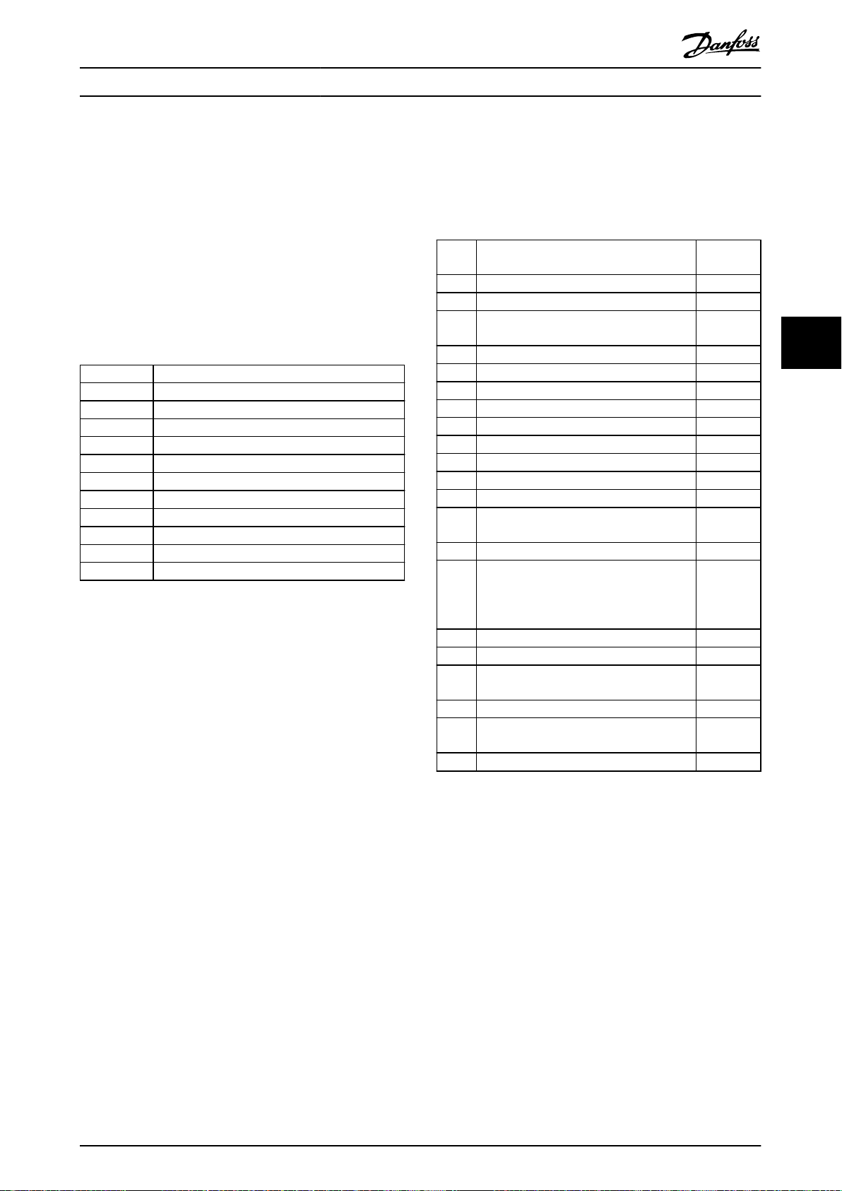
Parameter Access Programming Guide
description attribute (20 H) subindex=1. If bit 10 is set, a
descriptive text exists for each value of the parameter.
As an example, parameter 0-01 Language has settings 0–5.
For each of these values, a specic text exists: 0=English,
2=Deutsch, and so on.
5.2.19 Format
Species the format type for each parameter (word, byte,
and so on), see Table 5.12.
5.2.20 Supported Data types
Value Data type
3 Integer16
4 Integer32
5 Unsigned8
6 Unsigned16
7 Unsigned32
9 Visible string
10 Octet string (byte string)
33 N2 (standardised value)
35 V2 (bit sequence)
44 Error
54 Time dierence without date indication
Table 5.12 Supported Data Types
5.2.21 Value
The value eld contains the parameter value of the
request. When the response is negative, the eld contains
a corresponding fault code. If the values consist of an odd
number of bytes, a 0-byte is appended to maintain the
word structure of the telegrams.
For a positive partial response, the parameter value
contains the following attributes:
Format = Data type or byte, word, double word.
•
Number of values = Actual number of values.
•
Value = Parameter value.
•
For a negative partial response, the parameter value eld
contains the following:
Format = Error (44H).
•
Number of values = 1.
•
Value = Error value = Error number.
•
eld
5.2.22 Fault Codes for Drive Prole V 3.0
When the parameter request is invalid, the frequency
converter returns a corresponding fault code. Table 5.13
lists the full range of fault codes.
Fault
Description More Info
code
0x00 Unknown parameter. 0
0x01 Parameter is read-only. Subindex
0x02 Value out of range due to maximum/
minimum value.
0x03 Wrong subindex. Subindex
0x04 Parameter is no array. 0
0x05 Wrong data type (wrong data length). 0
0x06 This parameter may not be set, only reset. Subindex
0x07 Descriptive element is read-only. Subindex
0x09 No description available (only value). 0
0x0b Process control not possible. 0
0x0f No text array available (only value). 0
0x11 Not possible in current state. 0
0x14 Value out of range due to frequency
converter state/conguration.
0x15 Reply too long (more than 240 bytes). 0
0x16 Wrong parameter address (unknown or
unsupported value for attribute, element,
parameter number, or subindex, or illegal
combination).
0x17 Illegal format (for writing). 0
0x18 Value amount not consistent. 0
0x65 Wrong axis: Action not possible with this
axis.
0x66 Unknown service request. –
0x67 This service is not possible with multi-
parameter access.
0x68 Parameter value cannot be read from bus. –
Table 5.13 Fault Codes for DP-V1 Parameter Requests
PCV Parameter Access
5.3
The PROFINET cyclic data exchange performs parameter
access via the PCV channel. The PCV channel forms part of
the PPOs described in chapter 4 Control.
Use the PCV channel to read and write parameter values,
and read status for descriptive attributes of each
parameter.
Subindex
Subindex
0
–
–
5 5
5.3.1 PCA Handling
The PCA part of PPO types 1, 2, and 5 performs several
tasks. Using PCA, the master controls and supervises
parameters and requests a response from the slave. Then
the slave responds to a request from the master. Requests
and responses are a handshake procedure and cannot be
MG37G202 Danfoss A/S © 01/2016 All rights reserved. 31
Page 34

Parameter Access
VLT® PROFIBUS DP MCA 101
batched. Therefore, when the master sends out a read/
write request, it must wait for the response before it sends
a new request. The request or response data value is
limited to maximum 4 bytes (see RC characteristics in
Table 5.14), which implies that text strings are not
transferable. For further information, see
chapter 7 Application Examples.
5.3.2 PCA - Parameter Characteristics
15 14 13 12 11 10 9 8 7 6 5 4 3 2 1 0
RC SMP PNU
55
Table 5.14 PCA - Parameter Characteristics
RC: Request/response characteristics (range 0–15).
•
SMP: Spontaneous message (not supported).
•
PNU: Parameter no. (range 1–1999).
•
5.3.3 Request/Response Handling
The RC portion of the PCA word denes:
The requests issued from the master to the slave.
•
Other portions of the PCV involved:
•
- PVA: The PVA portion transmits word-
Response
When the slave rejects a request from the master, the RC
word in the PPO-read indicates the rejection by assuming
the value 7. Bytes 7 and 8 in the PVA element carry the
fault number.
The content of the RC portion of the PCA word for a
response is listed in Table 5.16.
Response Function
0 No response.
1 Transfer parameter value (word).
2 Transfer parameter value (long word).
3 Transfer description element.
4 Transfer parameter value (array word).
5 Transfer parameter value (array long word).
6 Transfer number of array elements.
7 Request rejected (including fault number, see
Table 5.17).
8 Not serviceable by PCV interface.
9 Not used.
10 Not used.
11 Not used.
12 Not used.
13–15 Not used.
Table 5.16 Response
size parameter values in bytes 7 and 8,
while long word size values require
bytes 5–8 (32 bits).
- IND: When the response/request
contains array elements, the IND carries
the array subindex. When parameter
descriptions are involved, the IND holds
the record subindex of the parameter
description.
5.3.4 RC Content
Request
The content of the RC portion of the PCA word for a
request is listed in Table 5.15.
Request Function
0 No request.
1 Request parameter value.
2 Change parameter value (word).
3 Change parameter value (long word).
4 Request description element.
5 Change description element.
6 Request parameter value (array).
7 Change parameter value (array word).
8 Change parameter value (array long word).
9 Request number of array elements.
10–15 Not used.
Fault
number
0 Illegal PNU.
1 Parameter value cannot be changed.
2 Upper or lower limit exceeded.
3 Subindex corrupted.
4 No array.
5 Data type false.
6 Cannot be set by user (reset only).
7 Description element cannot be changed.
8 IR required PPO-write not available.
9 Description data not available.
10 Access group.
11 No parameter write access.
12 Key word missing.
13 Text in cyclic transmission not readable.
14 Name in cyclic transmission not readable.
15 Text array not available.
16 PPO-write missing.
17 Request temporarily rejected.
18 Other fault.
19 Data in cyclic transmission not readable.
130 There is no bus access to the parameter called.
131 Data change is not possible because factory set-up is
Table 5.17 Fault Numbers
Interpretation
selected.
Table 5.15 Request
32 Danfoss A/S © 01/2016 All rights reserved. MG37G202
Page 35

Parameter Access Programming Guide
5.3.5 Example
This example shows
How to use PPO type 1 to change the ramp-up
•
time to 10 s in parameter 3-41 Ramp 1 Ramp Up
Time.
How to command a start and speed reference of
•
50%.
Frequency converter parameter settings:
Parameter 8-50 Coasting Select: [1] Bus.
•
Parameter 8-10 Control Word Prole: [1] PROFIdrive
prole.
5.3.5.1 PCV
PCA parameter characteristics
PCA part (byte 1–2).
The RC part tells what the PCV part must be used for. The
functions available are listed in chapter 5.3.1 PCA Handling.
When a parameter is changed, select value 2 or 3. In this
example, 3 is selected because parameter 3-41 Ramp 1
Ramp Up Time covers a long word (32 bits).
Parameter 3-41 Ramp 1 Ramp Up Time = 155 hex: In this
example, bytes 1 and 2 are set to 3155. See the values for
bytes 1 and 2 in chapter 5.3.5 Example.
IND (bytes 3–4)
Used when reading/changing parameters with subindex,
for example parameter 9-15 PCD Write Conguration. In the
example, bytes 3 and 4 are set to 00 hex. See the values
for bytes 3 and 4 in chapter 5.3.5 Example.
PVA (bytes 5–8)
Change the data value of parameter 3-41 Ramp 1 Ramp Up
Time to 10.00 s. The value transmitted must be 1000,
because the conversion index for parameter 3-41 Ramp 1
Ramp Up Time is 2. Therefore, the value received by the
frequency converter is divided by 100, such that the
frequency converter perceives 1000 as 10.00. Bytes 5–8 =
1000 = 03E8 hex. See chapter 5.4 PROFIBUS DP Parameter
and Data Type. See the values for bytes 5–8 in
chapter 5.3.5 Example.
These values are for bytes 9 and 10 in
chapter 5.3.5 Example.
Quick stop: 0000 0100 0110 1111=046F hex.
Stop: 0000 0100 0011 1111=043F hex.
5.4 PROFIBUS DP Parameter and Data Type
5.4.1 Parameter Description
PROFIBUS DP has a number of description attributes. Read/
write on parameter description is performed in the PCV
part using the RC commands 4 and 5, and the subindex of
the wanted description element.
5 5
5.3.5.2 PCD
Control word (CTW ) according to PROFIdrive prole:
Control words consist of 16 bits. The meaning of each bit
is explained in chapter 4.4.1 Control Word According to
PROFIdrive Prole (CTW ) and chapter 4.4.2 Status Word
According to PROFIdrive Prole (STW). The following bit
pattern sets all necessary start commands:
0000 0100 0111 1111=047F hex.
0000 0100 0111 1110=047E hex.
0000 0100 0111 1111=047F hex.
1) For restart after power-up:
Set bits 1 and 2 of the CTW to 1.
•
Toggle bit 0 0–1.
•
MG37G202 Danfoss A/S © 01/2016 All rights reserved. 33
1)
1)
Page 36

Parameter Access
VLT® PROFIBUS DP MCA 101
5.4.2 Size Attribute
Find the size index and the conversion index for each
parameter from the parameter list in the respective
operating instructions. See also size and conversion indices
in Table 5.18.
Physical
quantity
55
Time 4
Energy 8
Power 9
Rotation 11 Rotation per
Torque 16
Tempera-
ture
Voltage 21
Current 22
Resistance 23
Ratio 24 Percent % 0 1
Relative
change
Frequency 28
Size
SI unit name SI unit
index
0 No dimension
Second s 0 1
Millisecond ms -3 0.001
Minute min 70 60
Hour h 74 3600
Day d 77 86400
Watt hour Wh 0 1
Kilowatt hour kWh 3 1000
Megawatt hour MWh 6
Milliwatt mW -3 0.001
Watt W 0 1
Kilowatt kW 3 1000
Megawatt MW 6
minute
Newton meter Nm 0 1
Kilo newton
meter
17 Degree celsius ºC 0 1
Millivolt mV -3 0.001
Volt V 0 1
Kilovolt kV 3 1000
Milliampere mA -3 0.001
Ampere A 0 1
Kilo ampere kA 3 1000
Milliohm
Ohm
Kiloohm
27 Percent % 0 1
Hertz Hz 0 1
Kilohertz kHz 3 1000
Megahertz MHz 6
Gigahertz GHz 9
symbol
RPM 67 1
kNm 3 1000
mΩ
Ω
kΩ
Conver-
sion
index
-1 0.1
-2 0.01
-3 0.001
0 1
3 1000
Conver-
sion
factor
6
10
6
10
6
10
9
10
5.4.3 Object and Data Types Supported
Data type Short name Description
3 I2 Integer 16
4 I4 Integer 32
5 – Unsigned 8
6 O2 Unsigned 16
7 O4 Unsigned 32
9 – Visible string
10 – Byte string
33 N2 Standardized value (16 bit)
35 V2 Bit sequence
54 – Time dierence without date
indication
Table 5.19 Supported Data Types
5.4.4 Standardized Value
The frequency reference value transmits to the frequency
converter in the form of a 16-bit word. The value transmits
in integers (0–32767). The value 16384 (4000 hex)
corresponds to 100%. Negative numbers are formed with
the aid of the 2s complement.
0%=0 (0h), 100%=214 (4000 h)
Data type N2
Range -200% to +200%
Resolution
Length 2 bytes
Table 5.20 N2 Data Type
Msb is the
Bit Byte 1 Byte 2
8 SIGN
7
6
5
4
3
2
1
rst bit after the sign bit in the rst byte.
Sign bit = 0 = positive number.
•
Sign bit = 1 = negative number.
•
14
2
13
2
12
2
11
2
10
2
9
2
2 2
-14
2
=0.0061%
2
2
2
24
2
2
2
7
6
5
3
2
1
0
Table 5.18 Size Index and Conversion Index
34 Danfoss A/S © 01/2016 All rights reserved. MG37G202
Table 5.21 Notation is 2s Complement
Page 37

Parameter Access Programming Guide
Bit sequence
16 boolean values for control and presentation of user
functions.
Bit Byte 1 Byte 2
8 15 7
7 14 6
6 13 5
5 12 4
4 11 3
3 10 2
2 9 1
1 8 0
Table 5.22 Notation is Binary
5 5
MG37G202 Danfoss A/S © 01/2016 All rights reserved. 35
Page 38

Parameters
6 Parameters
VLT® PROFIBUS DP MCA 101
6
6.1 8-** PROFIBUS Parameters
This chapter describes the general parameters relating to
PROFIBUS and the communication settings of the
frequency converter.
Not all product series support all parameters, just as the
parameter settings may vary between the product series.
For details of the parameters in parameter groups 8-**
Comm. and Options, 9-** PROFIBUS, and 16-** Data
Readouts, refer to the programming guide of the
specic
product series.
8-01 Control Site
Option: Function:
The setting in this parameter overrides the
settings in parameter 8-50 Coasting Select to
parameter 8-56 Preset Reference Select.
[0] Digital and
ctrl.word
[1] Digital only Control by using digital inputs only.
[2] Controlword
only
Control by using both digital input and
control word.
Control by using control word only.
8-02 Control Word Source
Option: Function:
NOTICE
This parameter cannot be adjusted
while the motor is running.
Select the source of the control word: 1 of 2
serial interfaces or 4 installed options. During
initial power-up, the frequency converter
automatically sets this parameter to [3] Option
A if it detects a valid
in slot A. When the option is removed, the
frequency converter detects a conguration
change, sets parameter 8-02 Control Word
Source to default setting [1] FC RS485, and
trips. If an option is installed after initial
power-up, the setting of
parameter 8-02 Control Word Source does not
change, but the frequency converter trips and
shows: Alarm 67, Option Changed.
When retrotting a bus option into a
frequency converter that did not have a bus
option installed earlier, change the control to
bus-based. This change is required for safety
reasons to avoid an unintended change.
[0] None
[1] FC RS485
[2] FC USB
eldbus option installed
8-02 Control Word Source
Option: Function:
[3] Option A
[4] Option B
[5] Option C0
[6] Option C1
[30] External Can
8-03 Control Word Timeout Time
Range: Function:
1 s* [ 0.1 -
18000 s]
Enter the maximum time expected to pass
between the reception of 2 consecutive
telegrams. If this time is exceeded, it indicates
that the telegram communication has stopped.
The function selected in parameter 8-04 Control
Word Timeout Function is then carried out. A
valid control word triggers the timeout counter.
8-04 Control Word Timeout Function
Select the timeout function. The timeout function activates when
the control word fails to be updated within the time period
specied in parameter 8-03 Control Word Timeout Time.
Option: Function:
NOTICE
To change the set-up after a timeout,
congure as follows:
1. Set parameter 0-10 Active Set-
up to [9] Multi set-up.
2. Select the relevant link in
parameter 0-12 This Set-up
Linked to.
[0] O Resumes control via eldbus (eldbus or
standard), using the most recent control word.
[1] Freeze
output
[2] Stop Stops with auto restart when communication
[3] Jogging Runs the motor at jog frequency until
[4] Max. speed Runs the motor at maximum frequency until
[5] Stop and
trip
Freezes output frequency until communication
resumes.
resumes.
communication resumes.
communication resumes.
Stops the motor, then resets the frequency
converter to restart:
Via the eldbus.
•
Via [Reset].
•
Via a digital input.
•
36 Danfoss A/S © 01/2016 All rights reserved. MG37G202
Page 39

Parameters Programming Guide
8-04 Control Word Timeout Function
Select the timeout function. The timeout function activates when
the control word fails to be updated within the time period
specied in parameter 8-03 Control Word Timeout Time.
Option: Function:
[7] Select
setup 1
[8] Select
setup 2
[9] Select
setup 3
[10] Select
setup 4
[26] Trip
Changes the set-up after a control word
timeout. If communication resumes after a
timeout, parameter 8-05 End- of-Timeout
Function either resumes the set-up used before
the timeout, or retains the set-up endorsed by
the timeout function.
See [7] Select set-up 1.
See [7] Select set-up 1.
See [7] Select set-up 1.
8-05 End-of-Timeout Function
Option: Function:
Select the action after receiving a valid control
word following a timeout.
This parameter is active only when
parameter 8-04 Control Timeout Function is set
to:
[7] Set-up 1.
•
[8] Set-up 2.
•
[9] Set-up 3.
•
[10] Set-up 4.
•
[0] Hold set-upRetains the set-up selected in
parameter 8-04 Control Timeout Function and
shows a warning until parameter 8-06 Reset
Control Timeout toggles. Then the frequency
converter resumes its original set-up.
[1] * Resume
set-up
Resumes the set-up that was active before the
timeout.
8-06 Reset Control Word Timeout
This parameter is active only when [0] Hold set-up has been
selected in parameter 8-05 End-of-Timeout Function.
Option: Function:
[0] * Do not reset Retains the set-up specied in
parameter 8-04 Control Word Timeout Function,
following a control word timeout.
[1] Do reset Restores the frequency converter to the
original set-up following a control word
timeout. The frequency converter performs
the reset and then immediately reverts to the
[0] Do not reset setting.
8-07 Diagnosis Trigger
Option: Function:
Enables and controls the frequency converter
diagnosis function.
[0] * Disable Extended diagnosis data is not sent even if
the data appears in the frequency converter.
[1] Trigger on
alarms
[2] Trigger
alarm/warn.
Extended diagnosis data is sent when 1 or
more alarms appear.
Extended diagnosis data is sent if 1 or more
alarms/warnings appear.
8-10 Control Word Prole
Select the interpretation of the control and status words
corresponding to the installed eldbus. Only the selections valid
for the eldbus installed in slot A are visible in the LCP display.
For guidelines in selection of [0] Frequency converter prole and
[1] PROFIdrive prole, refer to the design guide of the related
product.
For more guidelines in the selection of [1] PROFIdrive prole, [5]
ODVA, and [7] CANopen DSP 402, see the installation guide for the
installed eldbus.
Option: Function:
[0] * FC prole
[1] PROFIdrive prole
[5] ODVA
[7] CANopen DSP 402
[8] MCO
8-50 Coasting Select
Option: Function:
Select control of the coasting function via the
terminals (digital input) and/or via the bus.
[0] Digital
input
[1] Bus Activates start command via the serial
[2] Logic AND Activates start command via the eldbus/serial
[3] * Logic OR Activates start command via the eldbus/serial
Activates start command via a digital input.
communication port or eldbus option.
communication port and 1 extra digital input.
communication port or via 1 of the digital
inputs.
8-51 Quick Stop Select
Select control of the quick stop function via the terminals (digital
input) and/or via the bus.
Option: Function:
[0] Digital input
[1] Bus
[2] Logic AND
[3] * Logic OR
6
6
MG37G202 Danfoss A/S © 01/2016 All rights reserved. 37
Page 40

Parameters
VLT® PROFIBUS DP MCA 101
6
8-52 DC Brake Select
Option: Function:
Select control of the DC brake via the terminals
(digital input) and/or via the eldbus.
NOTICE
When parameter 1-10 Motor Construction is
set to [1] PM non-salient SPM, only selection
[0] Digital input is available.
[0] Digital
input
[1] Bus Activates a start command via the serial communi-
[2] Logic
AND
[3] Logic OR Activates a start command via the eldbus/serial
8-53 Start Select
Option: Function:
[0] Digital
input
[1] Bus Activates a start command via the serial
[2] Logic
AND
[3] * Logic OR Activates a start command via the eldbus/
8-54 Reversing Select
Option: Function:
[0] Digital
input
[1] Bus Activates the reverse command via the serial
[2] Logic AND Activates the reverse command via the eldbus/
[3] Logic OR Activates the reverse command via the eldbus/
Activates a start command via a digital input.
cation port or eldbus option.
Activates a start command via the eldbus/serial
communication port, and also via 1 of the digital
inputs.
communication port, or via 1 of the digital inputs.
Select control of the frequency converter start
function via the terminals (digital input) and/or
via the eldbus.
Activates a start command via a digital input.
communication port or eldbus option.
Activates a start command via the eldbus/
serial communication port and also via 1 of the
digital inputs.
serial communication port or via 1 of the digital
inputs.
Select control of the frequency converter reverse
function via the terminals (digital input) and/or
via the eldbus.
communication port or eldbus option.
serial communication port and also via 1 of the
digital inputs.
serial communication port or via 1 of the digital
inputs.
8-55 Set-up Select
Option: Function:
Select control of the frequency converter set-up
selection via the terminals (digital input) and/or
via the eldbus.
[0] Digital
input
[1] Bus Activates the set-up selection via the serial
[2] Logic
AND
[3] * Logic OR Activates the set-up selection via the eldbus/
Activates the set-up selection via a digital input.
communication port or eldbus option.
Activates the set-up selection via the eldbus/
serial communication port and via 1 of the
digital inputs.
serial communication port or via 1 of the digital
inputs.
8-56 Preset Reference Select
Option: Function:
Select control of the preset reference selection
via the terminals (digital input) and/or via the
eldbus.
[0] Digital
input
[1] Bus Activates preset reference selection via the
[2] Logic AND Activates preset reference selection via the
[3] * Logic OR Activates the preset reference selection via the
Activates preset reference selection via a digital
input.
serial communication port or eldbus option.
eldbus/serial communication port and via 1 of
the digital inputs.
eldbus/serial communication port or via 1 of
the digital inputs.
8-90 Bus Jog 1 Speed
Range: Function:
100 RPM* [ 0 - par. 4-13
RPM]
Enter the jog speed. Activate this
xed jog speed via the serial port
or eldbus option.
8-91 Bus Jog 2 Speed
Range: Function:
200 RPM* [ 0 - par. 4-13
RPM]
Enter the jog speed. Activate this
xed jog speed via the serial port
or eldbus option.
38 Danfoss A/S © 01/2016 All rights reserved. MG37G202
Page 41

Parameters Programming Guide
6.2 9-** and 16-** PROFIBUS Parameters
9-15 PCD Write Conguration
Array [10]
Option: Function:
Select the parameters to be
assigned to PCD 3 to 10 of
the telegrams. The number of
available PCDs depends on
the telegram type. The values
in PCD 3 to 10 are then
written to the selected
parameters as data values.
Alternatively, specify a
standard PROFIBUS telegram
in parameter 9-22 Telegram
Selection.
[0] None
[302] Minimum Reference
[303] Maximum Reference
[341] Ramp 1 Ramp Up Time
[342] Ramp 1 Ramp Down Time
[351] Ramp 2 Ramp Up Time
[352] Ramp 2 Ramp Down Time
[380] Jog Ramp Time
[381] Quick Stop Ramp Time
[411] Motor Speed Low Limit
[RPM]
[412] Motor Speed Low Limit
[Hz]
[413] Motor Speed High Limit
[RPM]
[414] Motor Speed High Limit
[Hz]
[416] Torque Limit Motor Mode
[417] Torque Limit Generator
Mode
[553] Term. 29 High Ref./Feedb.
Value
[558] Term. 33 High Ref./Feedb.
Value
[590] Digital & Relay Bus
Control
[593] Pulse Out #27 Bus Control
[595] Pulse Out #29 Bus Control
[597] Pulse Out #X30/6 Bus
Control
[615] Terminal 53 High Ref./
Feedb. Value
[625] Terminal 54 High Ref./
Feedb. Value
[653] Terminal 42 Output Bus
Control
[663] Terminal X30/8 Output
Bus Control
9-15 PCD Write Conguration
Array [10]
Option: Function:
[673] Terminal X45/1 Bus
Control
[683] Terminal X45/3 Bus
Control
[890] Bus Jog 1 Speed
[891] Bus Jog 2 Speed
[894] Bus Feedback 1
[895] Bus Feedback 2
[896] Bus Feedback 3
[1680] Fieldbus CTW 1
[1682] Fieldbus REF 1
[1685] FC Port CTW 1
[1686] FC Port REF 1
9-16 PCD Read Conguration
[10] Array
Option: Function:
Select the parameters to be
assigned to PCD 3–10 of the
telegrams. The number of
available PCDs depend on
the telegram type. PCDs 3–
10 contain the actual data
values of the selected
parameters. For standard
PROFIBUS telegrams, see
parameter 9-22 Telegram
Selection.
[0] None
[894] Bus Feedback 1
[895] Bus Feedback 2
[896] Bus Feedback 3
[1397] Alert Alarm Word
[1398] Alert Warning Word
[1399] Alert Status Word
[1500] Operating hours
[1501] Running Hours
[1502] kWh Counter
[1600] Control Word
[1601] Reference [Unit]
[1602] Reference [%]
[1603] Status Word
[1605] Main Actual Value [%]
[1609] Custom Readout
[1610] Power [kW ]
[1611] Power [hp]
[1612] Motor Voltage
[1613] Frequency
[1614] Motor current
[1615] Frequency [%]
[1616] Torque [Nm]
6
6
MG37G202 Danfoss A/S © 01/2016 All rights reserved. 39
Page 42

Parameters
VLT® PROFIBUS DP MCA 101
6
9-16 PCD Read Conguration
[10] Array
Option: Function:
[1617] Speed [RPM]
[1618] Motor Thermal
[1622] Torque [%]
[1623] Motor Shaft Power [kW]
[1624] Calibrated Stator Resistance
[1626] Power Filtered [kW ]
[1627] Power Filtered [hp]
[1630] DC Link Voltage
[1632] Brake Energy /s
[1633] Brake Energy Average
[1634] Heatsink Temp.
[1635] Inverter Thermal
[1638] SL Controller State
[1639] Control Card Temp.
[1650] External Reference
[1652] Feedback[Unit]
[1653] Digi Pot Reference
[1654] Feedback 1 [Unit]
[1655] Feedback 2 [Unit]
[1656] Feedback 3 [Unit]
[1660] Digital Input
[1661] Terminal 53 Switch Setting
[1662] Analog Input 53
[1663] Terminal 54 Switch Setting
[1664] Analog Input 54
[1665] Analog Output 42 [mA]
[1666] Digital Output [bin]
[1667] Pulse Input #29 [Hz]
[1668] Pulse Input #33 [Hz]
[1669] Pulse Output #27 [Hz]
[1670] Pulse Output #29 [Hz]
[1671] Relay Output [bin]
[1672] Counter A
[1673] Counter B
[1675] Analog In X30/11
[1676] Analog In X30/12
[1677] Analog Out X30/8 [mA]
[1678] Analog Out X45/1 [mA]
[1679] Analog Out X45/3 [mA]
[1684] Comm. Option STW
[1685] FC Port CTW 1
[1690] Alarm Word
[1691] Alarm Word 2
[1692] Warning Word
[1693] Warning Word 2
[1694] Ext. Status Word
[1695] Ext. Status Word 2
[1696] Maintenance Word
[1830] Analog Input X42/1
[1831] Analog Input X42/3
[1832] Analog Input X42/5
9-16 PCD Read Conguration
[10] Array
Option: Function:
[1833] Analog Out X42/7 [V]
[1834] Analog Out X42/9 [V]
[1835] Analog Out X42/11 [V]
[1836] Analog Input X48/2 [mA]
[1837] Temp. Input X48/4
[1838] Temp. Input X48/7
[1839] Temp. Input X48/10
[1850] Sensorless Readout [unit]
[1860] Digital Input 2
9-18 Node Address
Range: Function:
126* [ 0 -
126 ]
Enter the station address in this parameter or,
alternatively, in the hardware switch. To adjust the
station address in parameter 9-18 Node Address,
set the hardware switch to 126 or 127 (all
switches set to ON). Otherwise, this parameter
shows the actual setting of the switch.
9-22 Telegram Selection
Option: Function:
Select a standard PROFIBUS telegram
conguration for the frequency
converter as an alternative to using
the freely congurable telegrams in
parameter 9-15 PCD Write Congu-
ration and parameter 9-16 PCD Read
Conguration.
[1] Standard telegram
1
[101] PPO 1
[102] PPO 2
[103] PPO 3
[104] PPO 4
[105] PPO 5
[106] PPO 6
[107] PPO 7
[108] * PPO 8
9-23 Parameters for Signals
Array [1000]
Read only
Option: Function:
This parameter
contains a list of
signals available for
selection in
parameter 9-15 PCD
Write Conguration
and
40 Danfoss A/S © 01/2016 All rights reserved. MG37G202
Page 43

Parameters Programming Guide
9-23 Parameters for Signals
Array [1000]
Read only
Option: Function:
parameter 9-16 PCD
Read Conguration.
[0] * None
[15] Readout: actual setup
[302] Minimum Reference
[303] Maximum Reference
[312] Catch up/slow Down Value
[341] Ramp 1 Ramp Up Time
[342] Ramp 1 Ramp Down Time
[351] Ramp 2 Ramp Up Time
[352] Ramp 2 Ramp Down Time
[380] Jog Ramp Time
[381] Quick Stop Ramp Time
[411] Motor Speed Low Limit [RPM]
[412] Motor Speed Low Limit [Hz]
[413] Motor Speed High Limit [RPM]
[414] Motor Speed High Limit [Hz]
[416] Torque Limit Motor Mode
[417] Torque Limit Generator Mode
[553] Term. 29 High Ref./Feedb. Value
[558] Term. 33 High Ref./Feedb. Value
[590] Digital & Relay Bus Control
[593] Pulse Out #27 Bus Control
[595] Pulse Out #29 Bus Control
[597] Pulse Out #X30/6 Bus Control
[615] Terminal 53 High Ref./Feedb. Value
[625] Terminal 54 High Ref./Feedb. Value
[653] Term 42 Output Bus Ctrl
[663] Terminal X30/8 Bus Control
[673] Terminal X45/1 Bus Control
[683] Terminal X45/3 Bus Control
[748] PCD Feed Forward
[890] Bus Jog 1 Speed
[891] Bus Jog 2 Speed
[1472] Legacy Alarm Word
[1473] Legacy Warning Word
[1474] Leg. Ext. Status Word
[1500] Operating hours
[1501] Running Hours
[1502] kWh Counter
[1600] Control Word
[1601] Reference [Unit]
[1602] Reference %
[1603] Status Word
[1605] Main Actual Value [%]
[1606] Absolute Position
[1609] Custom Readout
[1610] Power [kW ]
[1611] Power [hp]
[1612] Motor Voltage
9-23 Parameters for Signals
Array [1000]
Read only
Option: Function:
[1613] Frequency
[1614] Motor current
[1615] Frequency [%]
[1616] Torque [Nm]
[1617] Speed [RPM]
[1618] Motor Thermal
[1619] KTY sensor temperature
[1620] Motor Angle
[1621] Torque [%] High Res.
[1622] Torque [%]
[1623] Motor Shaft Power [kW]
[1624] Calibrated Stator Resistance
[1625] Torque [Nm] High
[1630] DC Link Voltage
[1632] Brake Energy /s
[1633] Brake Energy Average
[1634] Heatsink Temp.
[1635] Inverter Thermal
[1638] SL Controller State
[1639] Control Card Temp.
[1645] Motor Phase U Current
[1646] Motor Phase V Current
[1647] Motor Phase W Current
[1648] Speed Ref. After Ramp [RPM]
[1650] External Reference
[1651] Pulse Reference
[1652] Feedback[Unit]
[1653] Digi Pot Reference
[1657] Feedback [RPM]
[1660] Digital Input
[1661] Terminal 53 Switch Setting
[1662] Analog Input 53
[1663] Terminal 54 Switch Setting
[1664] Analog Input 54
[1665] Analog Output 42 [mA]
[1666] Digital Output [bin]
[1667] Freq. Input #29 [Hz]
[1668] Freq. Input #33 [Hz]
[1669] Pulse Output #27 [Hz]
[1670] Pulse Output #29 [Hz]
[1671] Relay Output [bin]
[1672] Counter A
[1673] Counter B
[1674] Prec. Stop Counter
[1675] Analog In X30/11
[1676] Analog In X30/12
[1677] Analog Out X30/8 [mA]
[1678] Analog Out X45/1 [mA]
[1679] Analog Out X45/3 [mA]
[1680] Fieldbus CTW 1
6
6
MG37G202 Danfoss A/S © 01/2016 All rights reserved. 41
Page 44

Parameters
VLT® PROFIBUS DP MCA 101
6
9-23 Parameters for Signals
Array [1000]
Read only
Option: Function:
[1682] Fieldbus REF 1
[1684] Comm. Option STW
[1685] FC Port CTW 1
[1686] FC Port REF 1
[1687] Bus Readout Alarm/Warning
[1689] Congurable Alarm/Warning Word
[1690] Alarm Word
[1691] Alarm Word 2
[1692] Warning Word
[1693] Warning Word 2
[1694] Ext. Status Word
[1836] Analog Input X48/2 [mA]
[1837] Temp. Input X48/4
[1838] Temp. Input X48/7
[1839] Temp. Input X48/10
[1843] Analog Out X49/7
[1844] Analog Out X49/9
[1845] Analog Out X49/11
[1860] Digital Input 2
[3310] Sync Factor Master
[3311] Sync Factor Slave
[3401] PCD 1 Write to MCO
[3402] PCD 2 Write to MCO
[3403] PCD 3 Write to MCO
[3404] PCD 4 Write to MCO
[3405] PCD 5 Write to MCO
[3406] PCD 6 Write to MCO
[3407] PCD 7 Write to MCO
[3408] PCD 8 Write to MCO
[3409] PCD 9 Write to MCO
[3410] PCD 10 Write to MCO
[3421] PCD 1 Read from MCO
[3422] PCD 2 Read from MCO
[3423] PCD 3 Read from MCO
[3424] PCD 4 Read from MCO
[3425] PCD 5 Read from MCO
[3426] PCD 6 Read from MCO
[3427] PCD 7 Read from MCO
[3428] PCD 8 Read from MCO
[3429] PCD 9 Read from MCO
[3430] PCD 10 Read from MCO
[3440] Digital Inputs
[3441] Digital Outputs
[3450] Actual Position
[3451] Commanded Position
[3452] Actual Master Position
[3453] Slave Index Position
[3454] Master Index Position
[3455] Curve Position
[3456] Track Error
9-23 Parameters for Signals
Array [1000]
Read only
Option: Function:
[3457] Synchronizing Error
[3458] Actual Velocity
[3459] Actual Master Velocity
[3460] Synchronizing Status
[3461] Axis Status
[3462] Program Status
[3464] MCO 302 Status
[3465] MCO 302 Control
[3470] MCO Alarm Word 1
[3471] MCO Alarm Word 2
[3644] Terminal X49/7 Bus Control
[3654] Terminal X49/9 Bus Control
[3664] Terminal X49/11 Bus Control
[4280] Safe Option Status
[4282] Safe Control Word
[4283] Safe Status Word
[4285] Active Safe Func.
[4287] Time Until Manual Test
9-27 Parameter Edit
Option: Function:
Edit parameters via:
PROFIBUS.
•
The standard RS485 interface.
•
The LCP.
•
[0] Disabled Disables editing via PROFIBUS.
[1] * Enabled Enables editing via PROFIBUS.
9-28 Process Control
Option: Function:
Process control (setting of control word, speed
reference, and process data) is possible via either
PROFIBUS or standard eldbus, but not both
simultaneously. Local control is always possible via
the LCP. Control via process control is possible via
either terminals or eldbus depending on the
settings in parameter 8-50 Coasting Select to
parameter 8-56 Preset Reference Select.
[0] Disable Disables process control via PROFIBUS master
class 1 and enables process control via standard
eldbus or PROFIBUS master class 2.
[1]*Enable
cyclic
master
Enables process control via PROFIBUS master class
1 and disables process control via standard
eldbus or PROFIBUS master class 2.
42 Danfoss A/S © 01/2016 All rights reserved. MG37G202
Page 45

Parameters Programming Guide
9-44 Fault Message Counter
Range: Function:
0* [0 -
65535 ]
Indicates the number of fault events presently
stored in parameter 9-45 Fault Code. The buer
capacity is maximum 8 error events. The buer
and counter are set to 0 by reset or power-up.
9-45 Fault Code
Range: Function:
0* [0 - 0 ] This buer contains the alarm word for all alarms
and warnings that have occurred since last reset or
power-up. The buer capacity is maximum 8 error
events.
9-47 Fault Number
Range: Function:
0* [0 - 0 ] This buer contains the alarm word for all alarms
and warnings that have occurred since last reset or
power-up. The buer capacity is maximum 8 error
events.
9-52 Fault Situation Counter
Range: Function:
0* [0 - 1000 ] Indicates the number of fault events that have
occurred since last reset or power-up.
9-53 Probus Warning Word
Read only
Range: Function:
0* [0 - 65535 ] This parameter shows PROFIBUS communi-
cation warnings. Refer to the VLT® PROFIBUS DP
MCA 101 Installation Guide for further
information.
Bit Description
0 Connection with DP-master is not OK.
1 Not used.
2 FDL (eldbus data link layer) is not OK.
3 Clear data command received.
4 Actual value is not updated.
5 Baud rate search.
6 PROFIBUS ASIC is not transmitting.
7 Initialization of PROFIBUS is not OK.
8 Frequency converter is tripped.
9 Internal CAN error.
10 Wrong conguration data from PLC.
11 Wrong ID sent by PLC.
12 Internal fault occurred.
13 Not congured.
14 Timeout active.
15 Warning 34, Fieldbus fault active.
9-63 Actual Baud Rate
Option: Function:
This parameter shows the actual
PROFIBUS baud rate. The PROFIBUS
master automatically sets the baud
rate.
[0] 9,6 kbit/s
[1] 19,2 kbit/s
[2] 93,75 kbit/s
[3] 187,5 kbit/s
[4] 500 kbit/s
[6] 1500 kbit/s
[7] 3000 kbit/s
[8] 6000 kbit/s
[9] 12000 kbit/s
[10] 31,25 kbit/s
[11] 45,45 kbit/s
[255] * No baudrate found
9-64 Device Identication
Range: Function:
0* [0 - 0] This parameter shows the device identication.
Refer to the VLT® PROFIBUS DP MCA 101 Installation
Guide for further explanation.
9-65 Prole Number
Range: Function:
0* [0 - 0 ] This parameter contains the prole identication.
Byte 1 contains the prole number and byte 2 the
version number of the prole.
9-70 Programming Set-up
This parameter is unique for LCP and eldbus. See
parameter 0-11 Programming Set-up.
Option: Function:
Select the set-up to edit.
[0] Factory setup Uses default data. This option can be used
as a data source to return the other set-ups
to a known state.
[1] Set-up 1 Edits set-up 1.
[2] Set-up 2 Edits set-up 2.
[3] Set-up 3 Edits set-up 3.
[4] Set-up 4 Edits set-up 4.
[9] * Active Set-up Follows the active set-up selected in
parameter 0-10 Active Set-up.
6
6
Table 6.1 PROFIBUS Warning Word
MG37G202 Danfoss A/S © 01/2016 All rights reserved. 43
Page 46

Parameters
VLT® PROFIBUS DP MCA 101
6
9-71 Probus Save Data Values
Option: Function:
Parameter values changed via PROFIBUS are not
automatically stored in non-volatile memory.
Use this parameter to activate a function that
stores parameter values in the EEPROM non-
volatile memory, so changed parameter values
are retained at power-down.
[0] * O Deactivates the non-volatile storage function.
[1] Store all
setups
[2] Store all
setups
Stores all parameter values for all set-ups in the
non-volatile memory. When all parameter values
have been stored, the selection returns to [0]
O.
Stores all parameter values for all set-ups in the
non-volatile memory. When all parameter values
have been stored, the selection returns to [0]
O.
9-72 ProbusDriveReset
Option: Function:
[0] * No action
[1] Power-on
reset
[3] Comm
option
reset
Resets the frequency converter after power-up,
as for power-cycle.
Resets the VLT® PROFIBUS DP MCA 101 option
only. This is useful after changing certain
settings in parameter group 9-** PROFIBUS, for
example, parameter 9-18 Node Address.
When reset, the frequency converter disappears
from the eldbus, which may cause a
communication error from the master.
9-80 Dened Parameters (1)
Array [116]
No LCP access
Read only
Range: Function:
0* [0 - 9999 ] This parameter shows a list of all the dened
frequency converter parameters available for
PROFIBUS.
9-81 Dened Parameters (2)
Array [116]
No LCP access
Read only
Range: Function:
0* [0 - 9999 ] This parameter shows a list of all the dened
frequency converter parameters available for
PROFIBUS.
9-82 Dened Parameters (3)
Array [116]
No LCP access
Read only
Range: Function:
0* [0 - 9999 ] This parameter shows a list of all the dened
frequency converter parameters available for
PROFIBUS.
9-83 Dened Parameters (4)
Array [116]
No LCP access
Read only
Range: Function:
0* [0 - 9999 ] This parameter shows a list of all the dened
frequency converter parameters available for
PROFIBUS.
9-90 Changed Parameters (1)
Array [116]
No LCP access
Read only
Range: Function:
0* [0 - 9999 ] This parameter shows a list of all the frequency
converter parameters deviating from default
setting.
9-91 Changed Parameters (2)
Array [116]
No LCP access
Read only
Range: Function:
0* [0 - 9999 ] This parameter shows a list of all the frequency
converter parameters deviating from default
setting.
9-92 Changed Parameters (3)
Array [116]
No LCP access
Read only
Range: Function:
0* [0 - 9999 ] This parameter shows a list of all the frequency
converter parameters deviating from default
setting.
9-93 Changed Parameters (4)
Range: Function:
0* [0 - 9999 ] This parameter shows a list of all the frequency
converter parameters deviating from default
setting.
44 Danfoss A/S © 01/2016 All rights reserved. MG37G202
Page 47

Parameters Programming Guide
9-94 Changed Parameters (5)
Array [116]
No LCP Address
Read only
Range: Function:
0* [0 - 9999 ] This parameter shows a list of all the frequency
converter parameters deviating from default
setting.
16-84 Comm. Option STW
Range: Function:
0* [0 - 65535 ] View the extended eldbus communication
option status word.
For more information, refer to the relevant
eldbus manual.
16-90 Alarm Word
Range: Function:
0* [0 - 4294967295 ] View the alarm word sent via the serial
communication port in hex code.
6
6
16-91 Alarm Word 2
Range: Function:
0* [0 - 4294967295] View the alarm word sent via the serial
communication port in hex code.
16-92 Warning Word
Range: Function:
0* [0 - 4294967295 ] View the warning word sent via the serial
communication port in hex code.
16-93 Warning Word 2
Range: Function:
0* [0 - 4294967295] View the warning word sent via the serial
communication port in hex code.
16-94 Ext. Status Word
Range: Function:
0* [0 - 4294967295] Returns the extended warning word sent
via the serial communication port in hex
code.
MG37G202 Danfoss A/S © 01/2016 All rights reserved. 45
Page 48

6
Parameters
VLT® PROFIBUS DP MCA 101
6.3 PROFIBUS-specic Parameter List
Parameter Default value Range Conversion index Data type
Parameter 8-01 Control Site [0] Dig. & ctrl. word [0–2] – Uint8
Parameter 8-02 Control Word Source [0] FC RS485 [0–4] – Uint8
Parameter 8-03 Control Word Timeout Time 1 0.1–18000 -1 Uint32
Parameter 8-04 Control Word Timeout Function [0] O [0–10] – Uint8
Parameter 8-05 End-of-Timeout Function [0] Hold set-up [0–1] – Uint8
Parameter 8-06 Reset Control Word Timeout [0] Do not reset [0–1] – Uint8
Parameter 8-07 Diagnosis Trigger [0] Disable [0–3] – Uint8
Parameter 8-10 Control Word Prole [0] FC prole [0–x] – Uint8
Parameter 8-50 Coasting Select *[3] Logic OR [0–3] – Uint8
Parameter 8-51 Quick Stop Select *[3] Logic OR [0–3] – Uint8
Parameter 8-52 DC Brake Select *[3] Logic OR [0–3] – Uint8
Parameter 8-53 Start Select *[3] Logic OR [0–3] – Uint8
Parameter 8-54 Reversing Select *[3] Logic OR [0–3] – Uint8
Parameter 8-55 Set-up Select *[3] Logic OR [0–3] – Uint8
Parameter 8-56 Preset Reference Select *[3] Logic OR [0–3] – Uint8
0–
parameter 4-13
Motor Speed
Parameter 8-90 Bus Jog 1 Speed 100 RPM
Parameter 8-91 Bus Jog 2 Speed 200 RPM
Parameter 9-15 PCD Write Conguration – – – Uint16
Parameter 9-16 PCD Read Conguration – – – Uint16
Parameter 9-18 Node Address 126 1–126 0 Uint8
Parameter 9-22 Telegram Selection – [0–108] – Uint8
Parameter 9-23 Parameters for Signals – 0–573 – Uint16
Parameter 9-27 Parameter Edit [1] Enabled [0–1] – Uint16
Parameter 9-28 Process Control [1] Enable cyclic master [0–1] – Uint16
Parameter 9-44 Fault Message Counter 0 [0–8] 0 Uint16
Parameter 9-45 Fault Code 0 – – Uint16
Parameter 9-47 Fault Number 0 – – Uint16
Parameter 9-52 Fault Situation Counter 0 0–1000 0 Uint16
Parameter 9-53 Probus Warning Word 0 16 bits 0 V2
Parameter 9-63 Actual Baud Rate [255] No baud rate found 9.6–12000 kbits 0 Uint8
Parameter 9-64 Device Identication 0 [0–10] 0 Uint16
Parameter 9-65 Prole Number 0 8 bits 0 Uint8
Parameter 9-70 Edit Set-up [9] Active set-up [0–9] – Uint8
Parameter 9-71 Probus Save Data Values [0] O [0–2] – Uint8
Parameter 9-72 ProbusDriveReset [0] No action [0-2] – Uint8
Parameter 9-80 Dened Parameters (1) – 0–115 0 Uint16
Parameter 9-81 Dened Parameters (2) – 0–115 0 Uint16
Parameter 9-82 Dened Parameters (3) – 0–115 0 Uint16
Parameter 9-83 Dened Parameters (4) – 0–115 0 Uint16
Parameter 9-90 Changed Parameters (1) – 0–115 0 Uint16
Parameter 9-91 Changed Parameters (2) – 0–115 0 Uint16
Parameter 9-92 Changed Parameters (3) – 0–115 0 Uint16
Parameter 9-93 Changed Parameters (4) – 0–115 0 Uint16
Parameter 9-94 Changed Parameters (5) – 0–115 0 Uint16
Parameter 16-84 Comm. Option STW 0 0–FFFF 0 V2
High Limit [RPM] 67 Uint16
0–
parameter 4-13
Motor Speed
High Limit [RPM] 67 Uint16
46 Danfoss A/S © 01/2016 All rights reserved. MG37G202
Page 49

Parameters Programming Guide
Parameter Default value Range Conversion index Data type
Parameter 16-90 Alarm Word 0 0–FFFF 0 Uint32
Parameter 16-92 Warning Word 0 0–FFFF 0 Uint32
Table 6.2 PROFIBUS-specic Parameter List
* Indicates a default setting.
Refer to the relevant operating instructions for a comprehensive parameter list.
6
6
MG37G202 Danfoss A/S © 01/2016 All rights reserved. 47
Page 50

Probus master
Probus
Relay 04-05
230 V AC
Ext. device
Sensor
Reversing
6362
18
20
19
0-24 V DC
130BA087.10
Application Examples
VLT® PROFIBUS DP MCA 101
7 Application Examples
7.1 Example 1: Process Data with PPO Type 6
This example shows how to work with PPO type 6, which consists of control word/status word and reference/main actual
value. The PPO also has 2 extra words, which can be programmed to monitor process signals:
PCV PCD
1 2 3 4 5 6 7 8 9 10
PCA IND PVA CTW MRV PCD PCD PCD PCD PCD PCD PCD PCD
STW MAV
Bit
number
Type 6
Table 7.1 Example: Process Data with PPO Type 6
1 2 3 4 5 6 7 8 9 10 11 12 13 14 15 16 17 18 19 20 21 22 23 24 25 26 27 28
77
The application requires monitoring of the motor torque
and digital input, so PCD 3 is set up to read the current
motor torque. PCD 4 is set up to monitor the state of an
external sensor via the process signal digital input. The
sensor is connected to digital input 18.
An external device is also controlled via control word bit
11 and the built-in relay of the frequency converter.
Reversing is allowed only when the reversing bit 15 in the
control word and the digital input 19 are set to high.
For safety reasons, the frequency converter stops the
motor if:
The PROFIBUS cable is broken.
•
The master has a system failure.
•
The PLC is in stop mode.
•
Illustration 7.1 Wiring Diagram
48 Danfoss A/S © 01/2016 All rights reserved. MG37G202
Page 51

Application Examples Programming Guide
Program the frequency converter as in Table 7.2:
Parameter Setting
Parameter 4-10 Motor Speed Direction [2] Both directions
Parameter 5-10 Terminal 18 Digital Input [0] No operation
Parameter 5-11 Terminal 19 Digital Input [10] Reversing
Parameter 5-40 Function Relay [36/37] Control word bit 11/12
Parameter 8-03 Control Word Timeout Time 1 s
Parameter 8-04 Control Word Timeout Function [2] Stop
Parameter 8-10 Control Word Prole [0] FC Prole
Parameter 8-50 Coasting Select [1] Bus
Parameter 8-51 Quick Stop Select [1] Bus
Parameter 8-52 DC Brake Select [1] Bus
Parameter 8-53 Start Select [1] Bus
Parameter 8-54 Reversing Select [2] Logic AND
Parameter 8-55 Set-up Select [1] Bus
Parameter 8-56 Preset Reference Select [1] Bus
Parameter 9-16 PCD Read Conguration [2] Sub index parameter 16-16 Torque [Nm]
[3] Sub index parameter 16-60 Digital Input
Parameter 9-18 Node Address Set the address
7 7
Table 7.2 Parameter Settings
Example 2: Control Word Telegram using PPO Type
7.2
This example shows how the control word telegram relates to the PLC and the frequency converter, using FC control prole.
The PLC sends the control word telegram to the frequency converter. In the example, PPO Type 3 demonstrates the full
range of modules. All the values shown are arbitrary and are provided for demonstration purposes only.
Table 7.3 indicates the bits contained within the control word, and how they are presented as process data in PPO type 3 for
this example.
PCV PCD
1 2 3 4 5 6
PCA IND PVA CTW MRV PCD PCD PCD PCD
04 7C 20 00
PQW 256 258 260 262 264 266 268 270 272 274
master slave CTW MRV
Bit
number
0 0 0 0 0 1 0 0 0 1 1 1 1 1 0 0
0 4 7 C
Table 7.3 Example: Control Word Telegram using PPO Type
15 14 13 12 11 10 9 8 7 6 5 4 3 2 1 0
MG37G202 Danfoss A/S © 01/2016 All rights reserved. 49
Page 52

Application Examples
VLT® PROFIBUS DP MCA 101
Table 7.4 indicates the bit functions and corresponding bit values which are active for this example.
Bit Bit value=0 Bit value=1 Bit value
00 Reference value External selection lsb 0
01 Reference value External selection msb 0
02 DC brake Ramp 1
03 Coasting Enable 1
04 Quick stop Ramp 1
05 Freeze output Ramp enable 1
06 Ramp stop Start 1
07 No function Reset 0
08 No function Jog 0
09 Ramp 1 Ramp 2 0
10 Data not valid Valid 1
11 No function Relay 01 active 0
12 No function Relay 02 active 0
13 Parameter set-up Selection lsb 0
77
14 Parameter set-up Selection msb 0
15 No function Reversing 0
Function active
Function inactive
C
7
4
0
Table 7.4 Active Bit Functions for Control Word Telegram using PPO Type
Example 3: Status Word Telegram using PPO Type
7.3
This example shows how the control word telegram relates to the PLC and the frequency converter, using FC control prole.
The PLC sends the control word telegram to the frequency converter. In the example, PPO type 3 demonstrates the full
range of modules. All the values shown are arbitrary and are provided for demonstration purposes only.
Table 7.5 indicates the bits contained within the status word, and how they are presented as process data in PPO type 3 for
this example.
PCV PCD
1 2 3 4 5 6
PCA IND PVA CTW MRV PCD PCD PCD PCD
0F 07 20 00
PIW 256 258 260 262 264 266 268 270 272 274
master slave STW MAV
Bit
number
0 0 0 0 0 1 0 0 0 1 1 1 1 1 0 0
0 4 7 C
Table 7.5 Example: Status Word Telegram using PPO Type
15 14 13 12 11 10 9 8 7 6 5 4 3 2 1 0
50 Danfoss A/S © 01/2016 All rights reserved. MG37G202
Page 53

Application Examples Programming Guide
Table 7.6 indicates the bit functions and the corresponding bit values which are active for this example.
Bit Bit value=0 Bit value=1 Bit value
00 Control not ready Control ready 1
01 Drive not ready Drive ready 1
02 Coasting Enable 1
03 No error Trip 0
04 No error Error (no trip) 0
05 Reserved – 0
06 No error Trip lock 0
07 No warning Warning 0
08 Speed reference Speed = reference 1
09 Local operation Bus control 1
10 Outside frequency range Within frequency range 1
11 No operation In operation 1
12 Drive OK Stopped, auto start 0
13 Voltage OK Voltage exceeded 0
14 Torque OK Torque exceeded 0
15 Timers OK Timers exceeded 0
Function active
Function inactive
7
0
F
0
7 7
Table 7.6 Active Bit Functions for Status Word Telegram using PPO Type
Example 4: PLC Programming
7.4
In this example, PPO type 6 is placed in the input/output address, see Illustration 7.2 and Table 7.7.
Illustration 7.2 FC 302 and PPO Type 6 PCD
Input
address
Set-up Status word MAV Motor
Table 7.7 Input/Output Address Set-up
256–257 258–259 260–261 262–263 Output
address
torque
Digital
input
Set-up Control
256–257 258–259 260–261 262–263
Reference Not used Not used
word
MG37G202 Danfoss A/S © 01/2016 All rights reserved. 51
Page 54

130BA110.10
Application Examples
VLT® PROFIBUS DP MCA 101
This network sends a start command (047C hex) and a
This network activates relay 02.
reference (2000 hex) of 50% to the frequency converter.
Illustration 7.7 Network Activates Relay 02
Illustration 7.3 Network Sends a Start Command and a
Reference of 50% to the Frequency Converter.
This network reads the motor torque from the frequency
converter. A new reference is sent to the frequency
converter because the motor torque (86.0%) is higher than
77
the compared value.
Illustration 7.4 Network Reads the Motor Torque from the
Frequency Converter
This network reads the status on the digital inputs from
the frequency converter. If digital input 18 is On, it stops
the frequency converter.
Illustration 7.5 Network Reads the Status on the Digital Inputs
from the Frequency Converter
This network reverses the motor when digital input 19 is
ON, because parameter 8-54 Reversing Select is
programmed to Logic AND.
Illustration 7.6 Network Reverses the Motor When Digital
Input 19 is ON
52 Danfoss A/S © 01/2016 All rights reserved. MG37G202
Page 55

Troubleshooting Programming Guide
8 Troubleshooting
8.1 Diagnosis
VLT® PROFIBUS DP MCA 101 provides a exible way of
performing diagnosis of slave units, based on diagnosis
messages.
During normal cyclic data exchange:
1. The slave sets a diagnosis bit, which requests the
master to send a diagnosis message during the
next scan cycle, instead of the normal data
exchange.
2. The slave answers the master with a diagnosis
message consisting of standard diagnosis
information, 6 bytes, and possibly extended,
vendor-specic, diagnosis information. The
standard diagnosis messages cover a limited
range of general diagnosis possibilities, whereas
the extended diagnosis function oers detailed
messaging specic to the frequency converter.
See chapter 8.3 Warnings and Alarms for the extended
diagnosis messages for the frequency converter.
A master or a network analyzing tool is able to translate
these diagnosis words into real text messages using the
GSD le.
NOTICE
DP-V1 diagnosis is supported for PROFIBUS SW version
2.X and later versions. The default setting of the
PROFIBUS option is DP-V1 diagnosis.
When DP-V0 diagnosis is required, change the setting
under DP slave Properties.
8.2 No Response to Control Signals
Check that:
The control word is valid.
•
When bit 10=0 in the control word, the frequency
converter does not accept the control word. The
default setting is bit 10=1. Set bit 10=1 via the
PLC.
The relationship between bits in the control word
•
and the terminal I/Os is correct.
Check the logical relationship in the frequency
converter. Set the logic to bit 3=1 and digital
input=1 to achieve a successful start.
Select the FC control mode, digital input, and/or serial
communication, using parameter 8-50 Coasting Select to
parameter 8-56 Preset Reference Select.
Selecting control mode for parameter 8-50 Coasting
Select, parameter 8-51 Quick Stop Select, and
parameter 8-52 DC Brake Select:
If [0] Digital input is selected, the terminals control the
coast and DC brake functions.
NOTICE
Coasting, quick stop, and DC brake functions are active
for logic 0.
Terminal Bit 02/03/04 Function
0 0 Coast/DC brake/Q-stop
0 1 Coast/DC brake/Q-stop
1 0 No coast/DC brake/Q-stop
1 1 No coast/DC brake/Q-stop
Table 8.1 [0] Digital Input
If [1] Serial communication is selected, commands are
activated only when given via serial communication.
Terminal Bit 02/03/04 Function
0 0 Coast/DC brake/Q-stop
0 1 No coast/DC brake/Q-stop
1 0 Coast/DC brake/Q-stop
1 1 No coast/DC brake/Q-stop
Table 8.2 [1] Serial Communication
If [2] Logic AND is selected, activate both signals to perform
the function.
Terminal Bit 02/03/04 Function
0 0 Coast/DC brake/Q-stop
0 1 No coast/DC brake/Q-stop
1 0 No coast/DC brake/Q-stop
1 1 No coast/DC brake/Q-stop
Table 8.3 [2] Logic AND
If [3] Logic OR is selected, activation of 1 signal activates
the function.
Terminal Bit 02/03/04 Function
0 0 Coast/DC brake/Q-stop
0 1 Coast/DC brake/Q-stop
1 0 Coast/DC brake/Q-stop
1 1 No coast/DC brake/Q-stop
Table 8.4 [3] Logic OR
8 8
MG37G202 Danfoss A/S © 01/2016 All rights reserved. 53
Page 56

Troubleshooting
VLT® PROFIBUS DP MCA 101
Selecting control mode for parameter 8-53 Start Select
and parameter 8-54 Reversing Select:
If [0] Digital input is selected, the terminals control the start
and reversing functions.
Terminal Bit 06/15 Function
0 0 Stop/clockwise
0 1 Stop/counterclockwise
1 0 Start/clockwise
1 1 Start/clockwise
Table 8.5 [0] Digital Input
If [1] Serial communication is selected, activate commands
only when given via serial communication.
Terminal Bit 02/03/04 Function
0 0 Stop/counterclockwise
0 1 Start/clockwise
1 0 Stop/counterclockwise
1 1 Start/clockwise
88
Table 8.6 [1] Serial Communication
If [2] Logic AND is selected, activate both signals to perform
the function.
Terminal Bit 02/03/04 Function
0 0 Stop/counterclockwise
0 1 Stop/counterclockwise
1 0 Stop/counterclockwise
1 1 Start/clockwise
Table 8.7 [2] Logic AND
If [3] Logic OR is selected, activation of 1 signal activates
the function.
Terminal Bit 02/03/04 Function
0 0 Stop/counterclockwise
0 1 Start/clockwise
1 0 Start/clockwise
1 1 Start/clockwise
Table 8.8 [3] Logic OR
Selecting control mode for parameter 8-55 Set-up Select
and parameter 8-56 Preset Reference Select:
If [0] Digital input is selected, the terminals control the setup and preset reference functions.
Terminal Bit 00/01, 13/14 Function
Msb Lsb Msb Lsb Preset reference, set-up
number
0 0 0 0 1
0 0 0 1 1
0 0 1 0 1
0 0 1 1 1
0 1 0 0 2
0 1 0 1 2
0 1 1 0 2
0 1 1 1 2
1 0 0 0 3
1 0 0 1 3
1 0 1 0 3
1 0 1 1 3
1 1 0 0 4
1 1 0 1 4
1 1 1 0 4
1 1 1 1 4
Table 8.9 [0] Digital Input
If [1] Serial communication is selected, activate commands
only when given via serial communication.
Terminal Bit 00/01, 13/14 Function
Msb Lsb Msb Lsb Preset reference, set-up
number
0 0 0 0 1
0 0 0 1 2
0 0 1 0 3
0 0 1 1 4
0 1 0 0 1
0 1 0 1 2
0 1 1 0 3
0 1 1 1 4
1 0 0 0 1
1 0 0 1 2
1 0 1 0 3
1 0 1 1 4
1 1 0 0 1
1 1 0 1 2
1 1 1 0 3
1 1 1 1 4
Table 8.10 [1] Serial Communication
If [2] Logic AND is selected, activate both signals to perform
the function.
54 Danfoss A/S © 01/2016 All rights reserved. MG37G202
Page 57

Troubleshooting Programming Guide
Terminal Bit 00/01, 13/14 Function
Msb Lsb Msb Lsb Preset reference, set-up
number
0 0 0 0 1
0 0 0 1 1
0 0 1 0 1
0 0 1 1 1
0 1 0 0 1
0 1 0 1 2
0 1 1 0 1
0 1 1 1 2
1 0 0 0 1
1 0 0 1 1
1 0 1 0 3
1 0 1 1 3
1 1 0 0 1
1 1 0 1 2
1 1 1 0 3
1 1 1 1 4
Table 8.11 [2] Logic AND
If [3] Logic OR is selected, activation of 1 signal activates
the function.
Terminal Bit 00/01, 13/14 Function
Msb Lsb Msb Lsb Preset reference, set-up
number
0 0 0 0 1
0 0 0 1 2
0 0 1 0 3
0 0 1 1 4
0 1 0 0 2
0 1 0 1 2
0 1 1 0 4
0 1 1 1 4
1 0 0 0 3
1 0 0 1 4
1 0 1 0 3
1 0 1 1 4
1 1 0 0 4
1 1 0 1 4
1 1 1 0 4
8 8
Table 8.12 [3] Logic OR
MG37G202 Danfoss A/S © 01/2016 All rights reserved. 55
Page 58

Troubleshooting
VLT® PROFIBUS DP MCA 101
8.3 Warnings and Alarms
NOTICE
Refer to the relevant operating instructions for an overview of warning and alarm types, and for the full list of warnings
and alarms.
Alarm word, warning word, and PROFIBUS warning word are shown on the frequency converter display in hex format. When
there is more than 1 warning or alarm, the sum of all warnings or alarms is shown. Alarm word, warning word, and
PROFIBUS warning word can also be shown using the eldbus in parameter 16-90 Alarm Word, parameter 16-92 Warning
Word, and parameter 9-53 Probus Warning Word.
Bit (hex) Dec Unit
diagnose bit
00000001 1 48 Brake check ServiceTrip, Read/Write 28
00000002 2 49 Power card overtemperature ServiceTrip (reserved) 29
00000004 4 50 Earth fault ServiceTrip, Typecode/
00000008 8 51 Control card over temperature ServiceTrip (reserved) 65
00000010 16 52 Control word timeout ServiceTrip (reserved) 18
00000020 32 53 Over current – 13
88
00000040 64 54 Torque limit – 12
00000080 128 55 Motor thermistor over temp. – 11
00000100 256 40 Motor ETR over temperature – 10
00000200 512 41 Inverter overloaded – 9
00000400 1024 42 DC-link undervoltage – 8
00000800 2048 43 DC-link overvoltage – 7
00001000 4096 44 Short circuit – 16
00002000 8192 45 Inrush fault – 33
00004000 16384 46 Mains phase loss – 4
00008000 32768 47 AMA not OK – 50
00010000 65536 32 Live zero error – 2
00020000 131072 33 Internal fault KTY error 38
00040000 262144 34 Brake overload Fans error 26
00080000 524288 35 Motor phase U is missing ECB error 30
00100000 1048576 36 Motor phase V is missing – 31
00200000 2097152 37 Motor phase W is missing – 32
00400000 4194304 38 Fieldbus comm. fault – 34
00800000 8388608 39 24 V supply fault – 47
01000000 16777216 24 Mains failure – 36
02000000 33554432 25 1.8 V supply fault – 48
04000000 67108864 26 Brake resistor short circuit – 25
08000000 134217728 27 Brake chopper fault – 27
10000000 268435456 28 Option change – 67
20000000 536870912 29 Drive initialisation – 80
40000000 1073741824 30 Safe stop PTC 1 Safe Stop (A71) 68
80000000 2147483648 31 Mechanical brake low Dangerous Failure (A72) 63
Alarm word (parameter 16-90 Alarm
Word)
Alarm word 2 Alarm
number
14
Sparepart
Table 8.13 Parameter 16-90 Alarm Word
56 Danfoss A/S © 01/2016 All rights reserved. MG37G202
Page 59

Troubleshooting Programming Guide
Bit (hex) Dec Unit
diagnose bit
00000001 1 112 Brake check – 28
00000002 2 113 Power card overtemperature – 29
00000004 4 114 Earth fault – 14
00000008 8 115 Control card – 65
00000010 16 116 Control word timeout – 18
00000020 32 117 Over current – 13
00000040 64 118 Torque limit – 12
00000080 128 119 Motor thermistor over temp. – 11
00000100 256 104 Motor ETR over temperature – 10
00000200 512 105 Inverter overloaded – 9
00000400 1024 106 DC-link undervoltage – 8
00000800 2048 107 DC-link overvoltage – 7
00001000 4096 108 DC -link voltage low – 6
00002000 8192 109 DC -link voltage high – 5
00004000 16384 110 Mains phase loss – 4
00008000 32768 111 No motor – 3
00010000 65536 96 Live zero error – 2
00020000 131072 97 10 V low KTY Warn 1
00040000 262144 98 Brake overload Fans Warn 26
00080000 524288 99 Brake resistor short circuit ECB Warn 25
00100000 1048576 100 Brake chopper fault – 27
00200000 2097152 101 Speed limit – 49
00400000 4194304 102 Fieldbus comm. fault – 34
00800000 8388608 103 24 V supply fault – 47
01000000 16777216 88 Mains failure – 36
02000000 33554432 89 Current limit – 59
04000000 67108864 90 Low temperature – 66
08000000 134217728 91 Voltage limit – 64
10000000 268435456 92 Encoder loss – 61
20000000 536870912 93 Output frequency limit – 62
40000000 1073741824 94 Unused PTC 1 Safe Stop (W71) –
80000000 2147483648 95 Warning word 2 (ext. stat. word) – –
Warning word (parameter 16-92 Warning
Word)
Warning word 2 Warning
number
8 8
Table 8.14 Parameter 16-92 Warning Word
MG37G202 Danfoss A/S © 01/2016 All rights reserved. 57
Page 60

Troubleshooting
VLT® PROFIBUS DP MCA 101
Bit hex Dec Extended status word
(parameter 16-94 Ext.
Status Word)
0 00000001 1 Ramping
1 00000002 2 AMA running
2 00000004 4 Start CW/CCW
3 00000008 8 Slow down
4 00000010 16 Catch up
5 00000020 32 Feedback high
6 00000040 64 Feedback low
7 00000080 128 Output current high
8 00000100 256 Output current low
9 00000200 512 Output freq hgh
10 00000400 1024 Output freq low
11 00000800 2048 Brake check OK
12 00001000 4096 Braking max
13 00002000 8192 Braking
14 00004000 16384 Out of speed range
15 00008000 32768 OVC active
16 00010000 65536 AC brake
88
17 00020000 131072 Password timelock
18 00040000 262144 Password protection
19 00080000 524288 –
20 00100000 1048576 –
21 00200000 2097152 –
22 00400000 4194304 Unused
23 00800000 8388608 Unused
24 01000000 16777216 Unused
25 02000000 33554432 Unused
26 04000000 67108864 Unused
27 08000000 134217728 Unused
28 10000000 268435456 Unused
29 20000000 536870912 Unused
30 40000000 1073741824 Unused
31 80000000 2147483648 Unused
Table 8.15 Extended Status Word
Bit (hex) Unit
diagnose
bit
00000001 160 Connection with DP-master is not OK.
00000002 161 Unused.
00000004 162 FDL (eldbus data link layer) is not OK.
00000008 163 Clear data command received.
00000010 164 Actual value is not updated.
00000020 165 Baud rate search.
00000040 166 PROFIBUS ASIC is not transmitting.
00000080 167 Initializing of PROFIBUS is not OK.
00000100 152 Frequency converter is tripped.
00000200 153 Internal CAN error.
00000400 154 Wrong conguration data from PLC.
00000800 155 Wrong ID sent by PLC.
00001000 156 Internal fault occurred.
00002000 157 Not congured.
00004000 158 Timeout active.
00008000 159 Warning 34, Fieldbus fault active
Table 8.16 Parameter 9-53 Probus Warning Word
Bit (hex) Communication option STW
(parameter 16-84 Comm. Option STW)
00000001 Parameterization OK.
00000002 Conguration OK.
00000004 Clear mode active.
00000008 Baud rate search.
00000010 Waiting for parameterization.
00000020 Waiting for conguration.
00000040 In data exchange.
00000080 Not used.
00000100 Not used.
00000200 Not used.
00000400 Not used.
00000800 MCL2/1 connected.
00001000 MCL2/2 connected.
00002000 MCL2/3 connected.
00004000 Data transport active.
00008000 Unused.
PROFIBUS warning word
(parameter 9-53 Probus Warning
Word)
Table 8.17 Parameter 16-84 Comm. Option STW
NOTICE
Parameter 16-84 Comm. Option STW is not part of
extended diagnosis.
For diagnosis, read out the alarm words, warning words,
and extended status words via eldbus or optional
eldbus.
Fault Messages via DP Diagnosis
8.4
The standard DP function features an online diagnosis,
which is active during DP initialization and data exchange
mode.
58 Danfoss A/S © 01/2016 All rights reserved. MG37G202
Page 61

Troubleshooting Programming Guide
8.5 Extended Diagnosis
Receive the extended diagnosis function, alarm, and
warning information from the frequency converter. The
setting of parameter 8-07 Diagnosis Trigger determines
which frequency converter events trigger the extended
diagnosis function:
When parameter 8-07 Diagnosis Trigger is set to [0]
•
Disable, no extended diagnosis data is sent
regardless of whether it appears in the frequency
converter or not.
When parameter 8-07 Diagnosis Trigger is set to [1]
•
Alarms, extended diagnosis data is sent when 1
or more alarms arrive in the alarm
parameter 16-90 Alarm Word or
parameter 9-53 Probus Warning Word.
When parameter 8-06 Reset Control Word Timeout is set to
[2] Alarms/Warnings, extended diagnosis data is sent if 1 or
more alarms/warnings arrive in the alarm
parameter 16-90 Alarm Word or parameter 9-53
Warning Word, or in the warning parameter 16-92 Warning
Word.
The extended diagnosis sequence is as follows:
If an alarm or warning appears, the frequency converter
sends a high-priority message to the master via the output
data telegram. The master then sends a request for
extended diagnosis information, to which the frequency
converter replies. When the alarm or warning disappears,
the frequency converter again sends a message to the
master, and on the following request from the master,
returns a standard DP diagnosis frame (6 bytes).
Probus
Byte Bit
number
0–5 – Standard DP diagnosis data.
6 – PDU length.
7 0–7 Status type=0x81.
8 8–15 Slot=0.
9 16–23 Status information.
10 24–31 Parameter 16-90 Alarm Word.
11 32–39 Parameter 16-90 Alarm Word.
12 40–47 Parameter 16-90 Alarm Word.
13 48–55 Parameter 16-90 Alarm Word.
14 56–63 Reserved for future use.
15 64–71 Reserved for future use.
16 72–79 Reserved for future use.
17 80–87 Reserved for future use.
18 88–95 Parameter 16-92 Warning Word.
19 96–103 Parameter 16-92 Warning Word.
20 104–111 Parameter 16-92 Warning Word.
21 112–119 Parameter 16-92 Warning Word.
22 120–127 Reserved for future use.
23 128–135 Reserved for future use.
24 136–143 Reserved for future use.
25 144–151 Reserved for future use.
26 152–159 Parameter 9-53 Probus Warning Word.
27 160–167 Parameter 9-53 Probus Warning Word.
28 168–175 Reserved for future use.
29 176–183 Reserved for future use.
30 184–191 Reserved for future use.
31 192–199 Reserved for future use.
Table 8.18 Content of the Extended Diagnosis Frame
Name
8 8
MG37G202 Danfoss A/S © 01/2016 All rights reserved. 59
Page 62

Index
VLT® PROFIBUS DP MCA 101
Index
A
Abbreviations........................................................................................... 5
Additional resources.............................................................................. 3
Alarm word............................................................................................. 56
Alarms....................................................................................................... 56
Approvals................................................................................................... 4
C
Certications............................................................................................. 4
Complete description......................................................................... 30
Conguration......................................................................................... 36
Control prole........................................................................................ 16
Control word.......................................................................................... 17
Conventions.............................................................................................. 5
CTW........................................................................................................... 17
D
Data store................................................................................................ 25
Data types, supported........................................................................ 34
Discharge time......................................................................................... 6
E
Extended diagnosis............................................................................. 59
F
Fault messages via DP diagnosis.................................................... 58
FC control mode
Digital input terminals................................................................... 16
Field PCD normalization.................................................................... 30
Freeze/unfreeze.................................................................................... 24
Frequency converter parameters................................................... 11
G
GSD le....................................................................................................... 9
H
High voltage............................................................................................. 6
I
ID extension............................................................................................ 30
Identier ID............................................................................................. 30
L
Leakage current....................................................................................... 7
LEDs........................................................................................................... 12
Load sharing............................................................................................. 6
Lower limit.............................................................................................. 30
M
MCT 10 Set-up Software....................................................................... 4
N
Name......................................................................................................... 30
Number of array elements................................................................ 30
P
Parameter access.................................................................................. 25
PCA handling......................................................................................... 32
PCA parameter characteristic........................................................... 32
PCD............................................................................................................ 33
PCD reference parameter.................................................................. 30
PCV............................................................................................................. 33
PCV parameter access......................................................................... 31
PPO types................................................................................................ 13
Process control data............................................................................ 15
Process control operation.................................................................. 16
Process data............................................................................................ 15
Process status data............................................................................... 15
PROFIBUS address................................................................................... 8
PROFIBUS DP-V1
Acyclic parameter channel........................................................... 27
Attribute description...................................................................... 30
Data exchange.................................................................................. 26
Fault codes......................................................................................... 31
Master class 1 connection............................................................. 26
Master class 2 connection............................................................. 26
Parameter access.............................................................................. 27
Read/write services......................................................................... 27
Request ID.......................................................................................... 29
Request reference............................................................................ 29
Request/response attributes....................................................... 28
Response ID....................................................................................... 29
Supported data types..................................................................... 31
Value..................................................................................................... 31
PROFIdrive
PROFIdrive state transition diagram.............................................. 20
prole (CTW)................................................................... 17
Q
Qualied personnel................................................................................ 6
R
RC content............................................................................................... 32
Read/write in double word format................................................. 25
Reference handling.............................................................................. 15
Request/response handling............................................................. 32
60 Danfoss A/S © 01/2016 All rights reserved. MG37G202
Page 63

Index Programming Guide
S
Safety........................................................................................................... 7
Services overview................................................................................. 26
Size attribute.......................................................................................... 34
Status word............................................................................................. 18
Symbols...................................................................................................... 5
Sync/unsync........................................................................................... 23
T
Termination switch................................................................................. 8
U
Unintended start..................................................................................... 6
Upper limit.............................................................................................. 30
W
Warning word........................................................................................ 56
Warnings.................................................................................................. 56
MG37G202 Danfoss A/S © 01/2016 All rights reserved. 61
Page 64

Danfoss can accept no responsibility for possible errors in catalogues, brochures and other printed material. Danfoss reserves the right to alter its products without notice. This also applies to
products already on order provided that such alterations can be made without subsequential changes being necessary in specications already agreed. All trademarks in this material are property
of the respective companies. Danfoss and the Danfoss logotype are trademarks of Danfoss A/S. All rights reserved.
Danfoss A/S
Ulsnaes 1
DK-6300 Graasten
vlt-drives.danfoss.com
130R0591 MG37G202 01/2016
*MG37G202*
 Loading...