

Page 1
Data Sheet
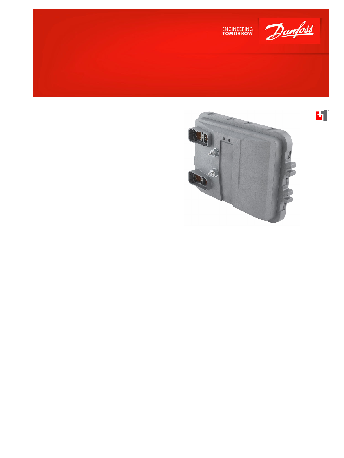
PLUS+1® Controllers
MC090-020 and MC090-022
Mobile Machine Management
This product is designed as flexible, expandable,
powerful, cost effective stand-alone modules for
smaller machined systems or as total machine
management systems with intelligence in every node.
These modules communicate with one another and
other intelligent systems over a machine Controller
Area Network (CAN data bus).
Product Highlights
The MC090 controller employs a Digital Signal
Processor (DSP), providing the controller with
extremely fast single-cycle processing speed and 1.3
MB flash.
The MC090-022 has an application key that enables
the use of Danfoss developed GUIDE machine control
solutions. The same GUIDE HWD file is used with both
controllers.
Application Development
PLUS+1® hardware modules have input or output
pins that support multiple functions. Pins that
support multiple input or output types are userconfigurable using PLUS+1® GUIDE software. This
Microsoft® Windows® based development
environment features a user-friendly, field proven,
icon-based graphical programming tool, application
downloader, and service/diagnostic tool.
Features
•
User-programmable with PLUS+1
GUIDE (Graphical User Integrated
Development Environment)
•
32 bit fixed-point DSP running at 150
MHz
•
12 bit analog-to-digital converter
•
2 MB serial flash vault memory
•
90 pins
®
‒
‒
‒
•
1 independent power supply for all
outputs except C2-P7, C2-P8, C2-P30
and C2-P35
•
1 independent CPU and start up
functions power supply 9 to 36 Vdc
(also provides power to C2-P38)
1: DEUTSCH DRC26-50 connector
1: DEUTSCH DRC26-38 connector
2: M5 power bolts
•
Power supply for external sensors rated
at 5 Vdc to 500 mA, regulated internally
•
2 LEDs, user controlled
•
2 Can 2.0B-ports
•
The MC090-022 contains an application
key required to run Danfoss developed
machine control application software
©
Danfoss | Jan 2017 AI00000202en-US0602 | 1
Page 2
Data Sheet
MC090-020 and MC090-022
•
8 user-defined inputs/outputs that are defined as
Digital inputs (DIN/DOUT 0.5 A)
‒
0.5 A Digital output: Configured as source only
‒
Inputs
•
42 user-defined inputs
18: Digital (DIN)
‒
11: Digital/Analog (DIN/AIN)
‒
4: Rheostat (Rheo)
‒
8: Digital with StartUp Function (DIN Start Up)
‒
1: Analog/CAN shield (AIN/CAN shield) configured as 0 to 5.25 Vdc or CAN shield pin
‒
Outputs
•
29 user-defined outputs
2: 0.5 A Digital: Configured as source only (DOUT 0.5 A)
‒
5: 1.5 A Digital: Configured as source only (DOUT 1.5 A)
‒
3: 3 A Digital: Configured as source only (DOUT 3 A)
‒
10: 6 A Digital/Digital Input: Configured as source only (DOUT 6 A)
‒
6: Universal (PWMOUT/DOUT) that are user-defined as either: Digital (1.5 A) configurable as source or sink; PWM (33 to 4000 Hz),
‒
configurable as open or closed loop with current control
2: Universal (PWMOUT/DOUT 15 A) that are user-defined as either: Digital (15 A) configurable as source or sink; PWM (13 kHz fixed),
‒
open loop mode only
1: 6 A PWM (195 Hz fixed), open loop and sourcing only
‒
Specifications
Product parameters
Supply voltage 9 to 36 Vdc
Operating temperature (ambient) -40°C to 70°C [-40°F to 158°F]
Storage temperature -40°C to 85°C [-40°F to 185°F]
Programming temperature 0°C to 70°C [32°F to 158°F]
IP rating (with mating connector attached) IP 67
EMI/RFI rating 100 V/M
Weight 1368 g [3.016 lb]
Maximum current, sourcing 86.5 A
Maximum current, sinking 85 A
2 | © Danfoss | Jan 2017 AI00000202en-US0602
Page 3
5041
10 35
37
29 34
13
3661
38
22
1
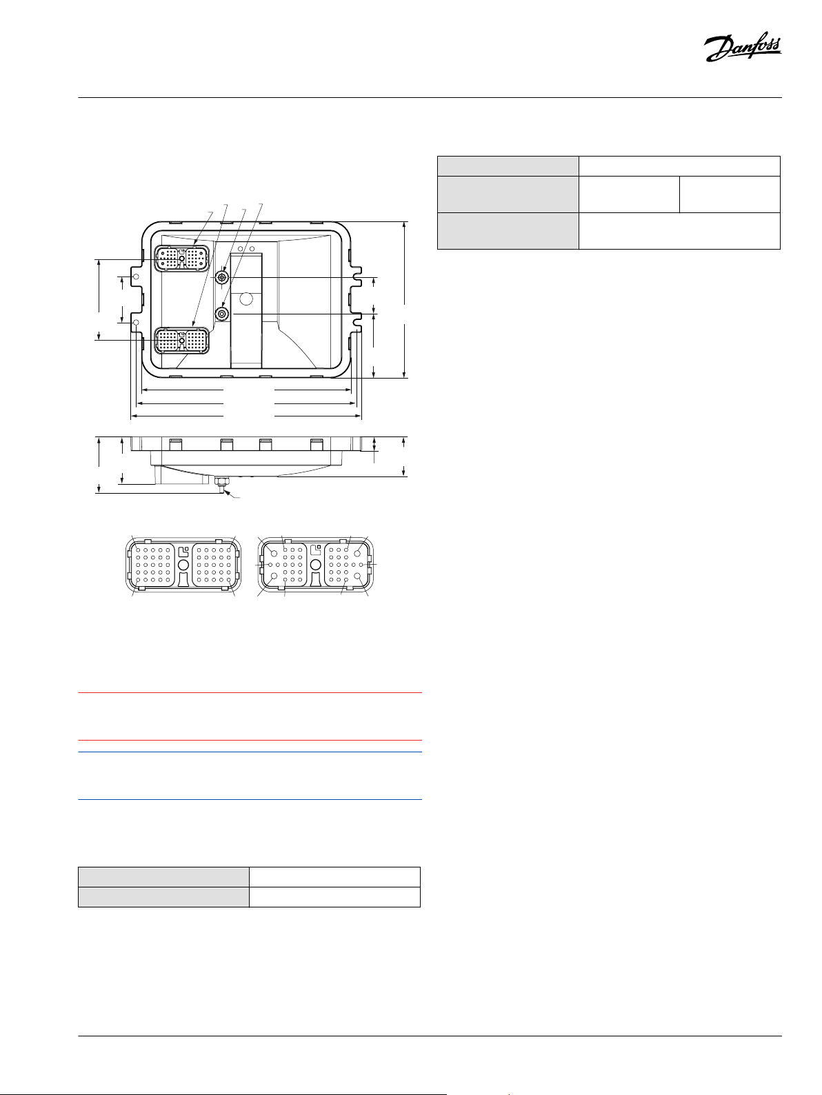
Connector 1: 50 pins
Connector 2: 38 pins
59.00
[2.32]
106 ± 0.20
[4.17 ± 0.01]
284.00 [11.18]
270.10 [10.63]
298.00 [11.73]
82.50
[3.25]
202.10
[7.95]
72.50
[2.85]
60.50
[2.38]
18.00
[0.71]
51.00
[2.01]
47.00
[1.85]
Bolt Connector
C2
C1
C3
C4
P109258
C
Data Sheet
MC090-020 and MC090-022
Dimensions
Mounting dimensions and pin assignments
Dimensions in mm [in]
Related products part numbers
CG150 CAN/USB Gateway 10104136
DEUTSCH mating
connector bag assembly
PLUS+1® GUIDE single user
license
11071844 (16 to 20
AWG)
10101000
10105649 (20 to 24
AWG)
This device is not field serviceable. Opening the device housing
will void the warranty.
This device’s entire back surface must be supported when
mounting (flatness within 1 mm). Mount device any direction.
Ordering information
Product part number
MC090-020 11081998
MC090-022 11162753
©
Danfoss | Jan 2017 AI00000202en-US0602 | 3
Caution
Page 4
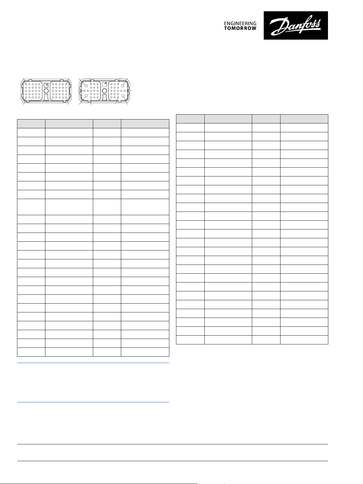
Pin connector
5041
10 35
37
29 34
13
3661
38
22
1
Connector 1: 50 pins
Connector 2: 38 pins
Pin C1 Controller function Pin C2 Controller function
C1-P1 DIN C2-P1 DOUT 0.5A/DIN
C1-P2 DIN C2-P2 DOUT 0.5A/DIN
C1-P3 CAN 0 + C2-P3 DOUT 0.5A/DIN
C1-P4 CAN 0 - C2-P4 DOUT 0.5A/DIN
C1-P5 CAN Shield/AIN C2-P5 DOUT 0.5A
C1-P6 N/A C2-P6 DOUT 0.5A
C1-P7 N/A C2-P7 DOUT 1.5A
C1-P8 Sensor Power + C2-P8 DOUT 1.5A
C1-P9 Sensor Power Ground-C2-P9 DOUT 1.5A
C1-P10 DIN C2-P10 DOUT 1.5A
C1-P11 DIN C2-P11 DOUT 1.5A
C1-P12 DIN C2-P12 DOUT 3A
C1-P13 DIN C2-P13 DOUT 3A
C1-P14 DIN C2-P14 DOUT 3A
C1-P15 DIN C2-P15 DOUT 6A
C1-P16 DIN C2-P16 DOUT 6A
C1-P17 DIN C2-P17 DOUT 6A
C1-P18 DIN C2-P18 DOUT 6A
C1-P19 DIN C2-P19 DOUT 6A
C1P20 DIN C2-P20 DOUT 6A
C1-P21 DIN C2-P21 DOUT 6A
C1-P22 DIN C2-P22 DOUT 6A
C1-P23 DIN C2-P23 DOUT 6A
C1-P24 DIN C2-P24 PWMOUT/DOUT 1.5A
C1-P25 DIN C2-P25 PWMOUT/DOUT 1.5A
Pin C1 Controller function Pin C2 Controller function
C1-P26 CAN 1+ C2-P26 PWMOUT/DOUT 1.5A
C1-P27 CAN 1 - C2-P27 PWMOUT/DOUT 1.5A
C1-P28 DIN/AIN C2-P28 PWMOUT/DOUT 1.5A
C1-P29 DIN/AIN C2-P29 PWMOUT/DOUT 1.5A
C1-P30 DIN/AIN C2-P30 PWMOUT/DOUT 6A
C1-P31 DIN/AIN C2-P31 DOUT 0.5A/DIN
C1-P32 DIN/AIN C2-P32 DOUT 0.5A/DIN
C1-P33 Rheo C2-P33 DOUT 0.5A/DIN
C1-P34 Rheo C2-P34 DOUT 0.5A/DIN
C1-P35 Rheo C2-P35 DOUT 6A
C1-P36 Rheo C2-P36 PWMOUT/DOUT 15A
C1-P37 DIN/AIN C2-P37 PWMOUT/DOUT 15A
C1-P38 DIN/AIN C2-P38 CPU Power (Batt +)
C1-P39 DIN/AIN - C1-P40 DIN/AIN - C1-P41 DIN/AIN - C1-P42 DIN/AIN - C1-P43 DIN StartUp - C1-P44 DIN StartUp - C1-P45 DIN StartUp - C1-P46 DIN StartUp - C1-P47 DIN StartUp - C1-P48 DIN StartUp - C1-P49 DIN StartUp - C1-P50 DIN StartUp - -
Use care when wiring mating connector. Pinouts listed are for
device pins.
CPU power supply C2-P38 also provides power to pins C2-P7, C2P8, C2-P30 and C2-P35 for start up functions.
Danfoss can accept no responsibility for possible errors in catalogues, brochures and other printed material. Danfoss reserves the right to alter its products without notice. This also applies to products
already on order provided that such alterations can be made without changes being necessary in specifications already agreed.
All trademarks in this material are property of the respective companies. Danfoss and the Danfoss logotype are trademarks of Danfoss A/S. All rights reserved.
4 | © Danfoss | Jan 2017 AI00000202en-US0602
 Loading...