

Page 1
Data Sheet
PLUS+1® Controllers
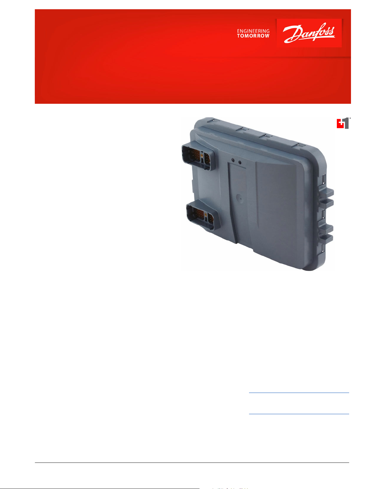
MC088-015 and MC088-01B
Mobile Machine Management
Danfoss PLUS+1® controllers are elements of the
flexible, powerful, expandable, and affordable family
of mobile machine management products. These
devices are general-purpose controllers that are
equally suited for use as members of a distributed
machine control system, with intelligence in every
node, or as stand-alone controllers.
Product Highlights
The MC088-015 and MC088-01B controllers employ a
Digital Signal Processor (DSP), providing the
controllers with extremely fast single cycle processing
speed and 256K internal flash. These controllers
feature 2 MB of serial flash vault memory reserved for
the application log feature of PLUS+1® GUIDE
software.
Application Development
The MC088-01B has an application key that enables
the use of Danfoss developed GUIDE machine control
solutions. The same GUIDE HWD file is used with both
controllers.
Users develop MC088-015 and MC088-01B
applications with PLUS+1® GUIDE. This Microsoft
Windows® based development environment features
a user-friendly, field proven, icon-based graphical
programming tool, application downloader, and
service/diagnostic tool.
Features
•
User-programmable with PLUS+1
GUIDE (Graphical User Integrated
Development Environment)
•
32 bit fixed-point DSP running at 150
MHz
•
12 bit analog-to-digital converter
•
2 MB serial flash vault memory
•
1 independent ECU power supply, 9 to
36 Vdc
®
®
•
4 independent power supplies for
powering output pins, 9 to 36 Vdc
•
2 CAN 2.0B ports, the fixed range analog
(AIN/CAN shield) pin may be configured
as a shield pin
•
Regulated 5 Vdc power supply for
external sensors rated at 500 mA
•
2 LEDs under user control
•
CE compliant
Comprehensive technical literature online
at powersolutions.danfoss.com
©
Danfoss | May 2017 11006645 | AI00000004en-US1502 | 1
Page 2
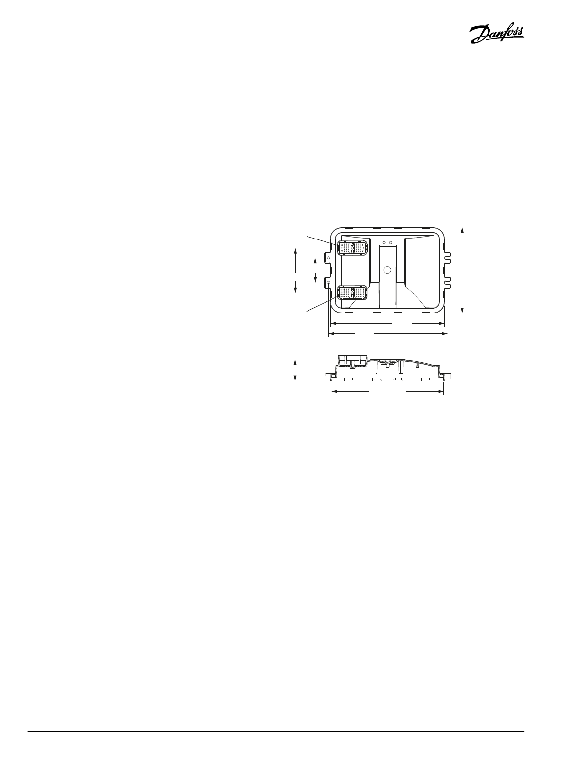
59.00
106 ± 0.20
50.99
202.05
270.05
284.00
263.23 ± 0.65
hkz1493136180153
C2
C1
C
Data Sheet
MC088-015 and MC088-01B
88 pins
•
1 DEUTSCH DRC26-50 connector
•
1 DEUTSCH DRC26-38 connector
42 inputs
•
6 universal (DIN/AIN/FreqIN) that are
user-defined as either
Analog: With configurable ranges 0
‒
to 5.25 Vdc or 0 to 36 Vdc
Digital: Pull up (5 Vdc), pull down (0
‒
Vdc) or pull to center (2.5 Vdc)
Frequency (timing): 1 Hz to 10 kHz
‒
•
18 digital (DIN) configurable as pull up
(5 Vdc), pull down (0 Vdc)
•
4 digital/analog (DIN/AIN). Digital inputs
have the same characteristics as DIN
pins, analog input ranges are user
configurable as 0 to 5.25 Vdc or 0 to 36
Vdc
•
8 analog (AIN/Temp/Rheo) configurable
as 0 to 5.25 Vdc or 0 to 10000 Ohm
range
•
4 digital/analog/current (DIN/AIN/4-20
ma IN). Digital inputs have the same
characteristics as DIN pins; Analog input
ranges are configurable as 0 to 5.25 Vdc
or 0 to 36 Vdc; inputs can be configured
to measure current with a 4 to 20 mA
range
•
2 fixed range analog (AIN/CAN shield)
configured as 0 to 5.25 Vdc or CAN
shield pin
Digital: (3 A) source or sink
‒
PWM: (3 A, 30 to 4000 Hz)
‒
configurable as open or closed loop
with current control
Analog voltage: open loop PWM at
‒
4000 Hz
Any PWMOUT/DOUT/PVGOUT can
‒
be used to provide reference power
to one PVG valve
Dimensions in millimeters
Caution
Warranty will be voided if device is opened.
Device is not field serviceable. Do not open
the device.
32 outputs
•
Outputs are powered by four
independent power supply pins
•
13 digital (DOUT) 3 A configurable as
source only
•
6 digital (HDOUT) 6 A configurable as
source only
•
3 digital/PVG power supply (DOUT/PVG
Pwr) 3 A configured to be either DOUT
or PVG supply power (one DOUT/PVG
Pwr pin will power up to three PVGs)
•
10 universal (PWM/DOUT/PVGOUT)
configured to be either
2 | © Danfoss | May 2017 11006645 | AI00000004en-US1502
Page 3

50
41
10 35
37
29
34
13
3661
38
22
1
glb1493136109548
C2C1
Data Sheet
MC088-015 and MC088-01B
Use care when wiring mating connector. Pinouts are for device
pins.
50 pin - C1 and 38 pin - C2 connectors
50 pin connector - C1
Pin Controller function Pin Controller function
C1-P1 CPU power ground - C1-P26 DIN/AIN/FreqIN
C1-P2 CPU power supply + C1-P27 AIN/Temp/Rheo
C1-P3 CAN0+ C1-P28 AIN/Temp/Rheo
C1-P4 CAN0- C1-P29 AIN/Temp/Rheo
C1-P5 AIN/CAN0 shield C1-P30 AIN/Temp/Rheo
C1-P6 DIN C1-P31 DOUT (3 A –Pwr = C2P35)
C1-P7 DIN C1-P32 DOUT (3 A –Pwr = C2P35)
C1-P8 5 Vdc sensor power + C1-P33 DOUT (3 A –Pwr = C2P35)
C1-P9 Sensor power ground - C1-P34 DOUT/PVG Pwr (3 A –Pwr = C2P35)
C1-P10 DIN C1-P35 DOUT/PVG Pwr (3 A –Pwr = C2P36)
C1-P11 DIN C1-P36 DOUT/PVG Pwr (3 A –Pwr = C2P36)
C1-P12 DIN C1-P37 PWMOUT/DOUT/PVG OUT (3 A—Pwr = C2P35)
C1-P13 DIN C1-P38 PWMOUT/DOUT/PVG OUT (3 A—Pwr = C2P35)
C1-P14 DIN/AIN C1-P39 PWMOUT/DOUT/PVG OUT (3 A—Pwr = C2P35)
C1-P15 DIN/AIN C1-P40 PWMOUT/DOUT/PVG OUT (3 A—Pwr = C2P35)
C1-P16 DIN/AIN C1-P41 PWMOUT/DOUT/PVG OUT (3 A—Pwr = C2P36)
C1-P17 DIN/AIN C1-P42 PWMOUT/DOUT/PVG OUT (3 A—Pwr = C2P36)
C1-P18 DIN/AIN/FreqIN C1-P43 PWMOUT/DOUT/PVG OUT (3 A—Pwr = C2P36)
C1-P19 DIN/AIN/FreqIN C1-P44 PWMOUT/DOUT/PVG OUT (3 A—Pwr = C2P36)
C1-P20 CAN1+ C1-P45 PWMOUT/DOUT/PVG OUT (3 A—Pwr = C2P36)
C1-P21 CAN1- C1-P46 PWMOUT/DOUT/PVG OUT (3 A—Pwr = C2P36)
C1-P22 AIN/CAN1 shield C1-P47 DIN/AIN//4-20 mA IN
C1-P23 DIN/AIN/FreqIN C1-P48 DIN/AIN//4-20 mA IN
C1-P24 DIN/AIN/FreqIN C1-P49 DIN/AIN//4-20 mA IN
C1-P25 DIN/AIN/FreqIN C1-P50 DIN/AIN//4-20 mA IN
©
Danfoss | May 2017 11006645 | AI00000004en-US1502 | 3
Page 4

38 pin connector - C2
Pin Controller function Pin Controller function
C2-P1 DOUT (3 A –Pwr = C2P37) C2-P20 Power ground C2-P2 DOUT (3 A –Pwr = C2P37) C2-P21 DIN
C2-P3 DOUT (3 A –Pwr = C2P37) C2-P22 HDOUT (6 A—Pwr = C2P38)
C2-P4 DOUT (3 A –Pwr = C2P37) C2-P23 DIN
C2-P5 DOUT (3 A –Pwr = C2P37) C2-P24 DIN
C2-P6 DOUT (3 A –Pwr = C2P38) C2-P25 DIN
C2-P7 DOUT (3 A –Pwr = C2P37) C2-P26 DIN
C2-P8 AIN/Temp/Rheo C2-P27 DIN
C2-P9 AIN/Temp/Rheo C2-P28 DIN
C2-P10 AIN/Temp/Rheo C2-P29 HDOUT (6 A –Pwr = C2P37)
C2-P11 AIN/Temp/Rheo C2-P30 DOUT (2 A –Pwr = C2P37)
C2-P12 DOUT (3 A –Pwr = C2P38) C2-P31 HDOUT (6 A –Pwr = C2P38)
C2-P13 HDOUT (6 A –Pwr = C2P37) C2-P32 HDOUT (6 A –Pwr = C2P38)
C2-P14 Power ground - C2-P33 DOUT (2 A –Pwr = C2P37)
C2-P15 DIN C2-P34 HDOUT (6 A –Pwr = C2P38)
C2-P16 DIN C2-P35
C2-P17 DIN C2-P36
C2-P18 DIN C2-P37
C2-P19 DIN C2-P38
*
Power supply + pin C2-P35 and C2-P36 should each be protected with a 25 A fuse.
**
C2-P37 and C2-P38 should each be protected with a 30 A fuse.
*
1
**
2
Power supply + (20 A)
Power supply + (22 A)
Power supply + (28 A)
Power supply + (28 A)
Product parameters
Supply voltage 9 to 36 V
Operating temperature
(ambient)
Storage temperature -40°C to 85°C [-40°F to 185°F]
Programming
temperature
IP rating (with mating
connector attached)
EMI/RFI rating 100 V/M
Weight 964 g [2.125 lb]
Maximum current,
sourcing
Maximum current, sinking 24 A (with all ground pins connected)
DC
-40°C to 70°C [-40°F to 158°F]
0°C to 70°C [32°F to 158°F]
IP 67
100 A (with all power supply and pins
connected)
Ordering information
Product part number
MC088-015 10105470
MC088-01B 11071592
Related products part numbers
CG150 CAN/USB Gateway 11153051
DEUTSCH mating connector bag
assembly
PLUS+1® GUIDE Professional 11179523
11071844
(16 to 20 AWG)
10105649
(20 to 24 AWG)
Danfoss can accept no responsibility for possible errors in catalogues, brochures and other printed material. Danfoss reserves the right to alter its products without notice. This also applies to products
already on order provided that such alterations can be made without changes being necessary in specifications already agreed.
All trademarks in this material are property of the respective companies. Danfoss and the Danfoss logotype are trademarks of Danfoss A/S. All rights reserved.
4 | © Danfoss | May 2017 11006645 | AI00000004en-US1502
 Loading...