

Page 1
Data Sheet
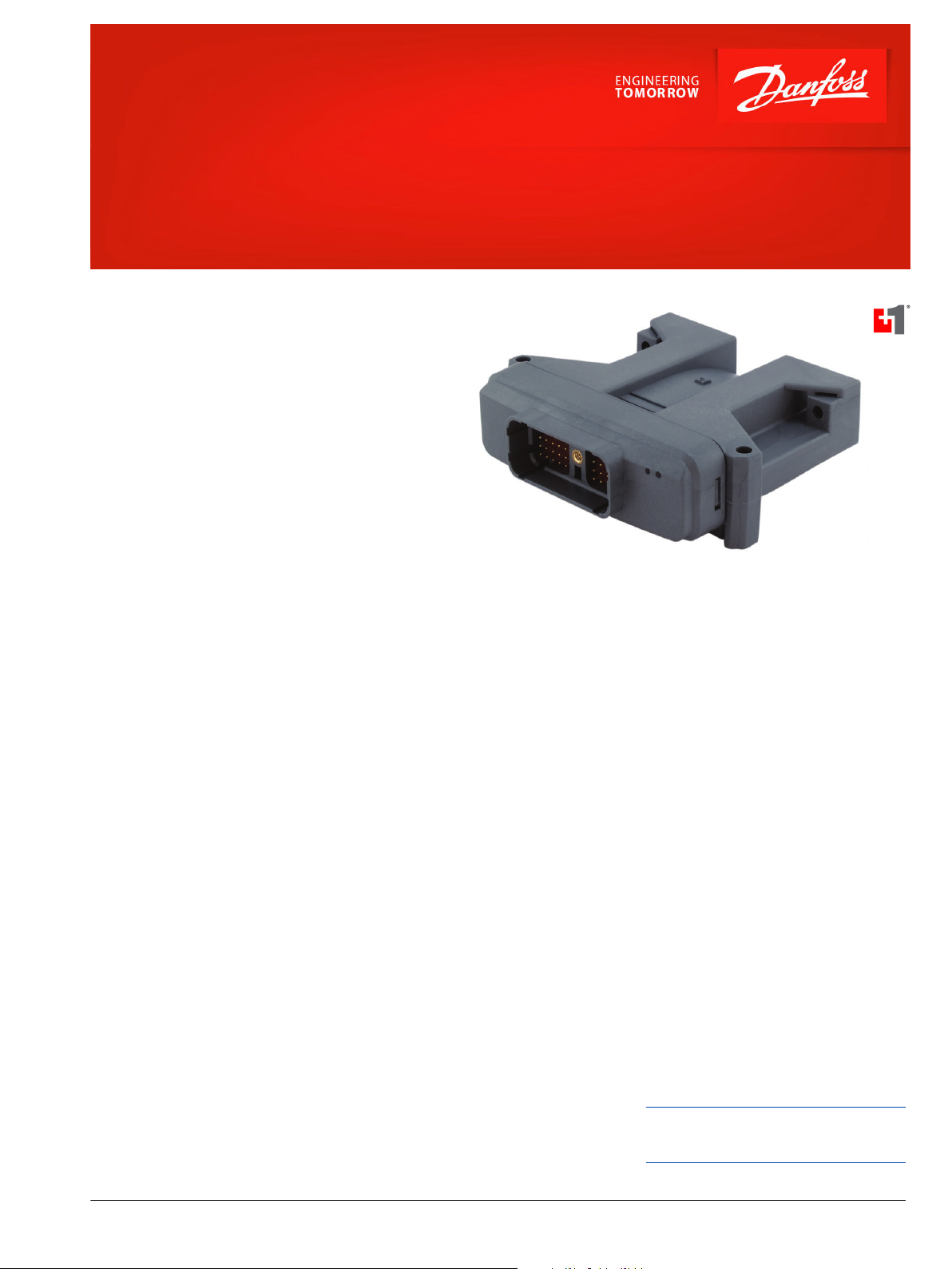
PLUS+1® Controllers
MC050-155 and MC050-15B
Mobile machine management
The MC050-155 and MC050-15B controllers are
elements of the flexible, powerful, expandable, and
affordable PLUS+1® family of mobile machine
management products. These devices are generalpurpose controllers that are equally suited for use as
members of a distributed machine control system,
with intelligence in every node, or as stand-alone
controllers.
Product highlights
Both controllers employ a 32 bit Cortex-M3 Processor,
providing the controllers with extremely fast single
cycle processing speed and 512K internal flash. Both
controllers feature three CAN ports, one 1.66 and one
3.3 or 5 volt regulated sensor supply. The MC050-15B
has an application key that enables the use of Danfoss
developed GUIDE machine control solutions. The
same GUIDE HWD file is used with both controllers.
Application development
Users develop MC050-155 and MC050-15B
applications with PLUS+1® GUIDE. This Microsoft
Windows® based development environment features
a user-friendly, field proven, icon-based graphical
programming tool, application downloader, and
service/diagnostic tool.
Features
•
User-programmable with PLUS+1
GUIDE (Graphical User Integrated
Development Environment)
•
50 pins: (1) DEUTSCH DRC connector
•
ARM 32 bit Cortex-M3 running at 120
MHz
•
FRAM non-volatile memory
•
12 bit analog-to-digital converter
•
9 to 36 Vdc power supply, monitored
internally
®
®
•
3 CAN 2.0 B ports, the fixed range
analog inputs can be used as the shield
pin
•
Power supply for external sensors,
monitored and regulated internally
‒
‒
‒
•
2 LEDs under user control
1.6 Vdc rated at 500 mA
3.3 Vdc rated at 450 mA
5.0 Vdc rated at 450 mA
•
3 mounting alternatives: stack, end, or
side
•
MC050-15B contains application key
required to run Danfoss developed
machine control application software
•
CE compliant
Comprehensive technical literature is
online at www.danfoss.com
©
Danfoss | June 2020 AI152986480798en-000403 | 1
Page 2

Data Sheet
MC050-155 and 15B Controllers
36 inputs
•
4 universal (DIN/AIN/FreqIN) that are user-defined as either:
Analog: with configurable ranges 0 to 5.25 Vdc (with over range protection) or 0 to 36 Vdc
‒
Digital: pull up (5 Vdc), pull down (0 Vdc) or pull to center (2.5 Vdc)
‒
Frequency (timing): 1 Hz to 10 kHz
‒
•
29 digital/analog (DIN/AIN) that are user-defined as either:
Digital: pull up (5 Vdc), pull down (0 Vdc) or pull to center (2.5 Vdc)
‒
Analog: 0 to 5.25 Vdc or 0 to 36 Vdc
‒
•
3 fixed range analog (AIN/CAN shield) 0 to 5.25 Vdc or CAN shield pin
3 outputs
•
2 universal (PWMOUT/DOUT/PVGOUT) that are user-defined as either:
Digital: (3 A), configurable as source or sink
‒
PWM: (30 to 4000 Hz), configurable as open or closed loop with current control
‒
Analog voltage: open loop PWM at 4000 Hz
‒
•
Any PWMOUT/DOUT/PVGOUT can be used to provide reference power to one PVG valve
•
1 digital/PVG Pwr (DOUT/PVG Pwr) sourcing only one DOUT/PVG Pwr will power up to 3 PVGs
2 | © Danfoss | June 2020 AI152986480798en-000403
Page 3

114.4 [4.50]
159.7 [6.29]
25.2 [1.0]
143.3 [5.64]
97.0
[3.82]
35.0 [1.38]
51.6 [2.03]
47.1 [1.85]
144.5 [5.69]
C
Data Sheet
MC050-155 and 15B Controllers
Dimensions
mm [in]
Caution
PCB damage may occur. All device power supply + pins must be connected to battery +.
This device is not field serviceable. Opening the device housing will void the warranty.
Technical specifications
Supply voltage 9 to 36 Vdc
Operating temperature (ambient) -40°C to 70°C [-40°F to 158°F]
Storage temperature -40°C to 85°C [-40°F to 185°F]
Programming temperature -40°C to 70°C [-40°F to 158°F]
IP rating (with mating connector
attached)
EMI/RFI rating 100 V/m
Weight 0.40 kg [0.88 lb]
Maximum current, sourcing 8 A
Maximum current, sinking 6 A
IP 67
Related product Danfoss material number
CG150 CAN/USB
Gateway
DEUTSCH mating
connector bag
assembly
PLUS+1® GUIDE single
user license
Ordering information
MC050-155 11130958
MC050-15B 11130959
10104136
10102024
(16 to 20 AWG)
10101079
10100946
(20 to 24 AWG)
©
Danfoss | June 2020 AI152986480798en-000403 | 3
Page 4

Pin information
2198B
1 2 3 4 5
11 12 13 14 15
2524232221
3534333231
4544434241
6 7 8 9 10
16 17 18 19 20
3029282726
4039383736
5049484746
50-pin connector
Pin Controller
function
Pin Controller
function
C1-P1 Power ground - C1-P26 DIN/AIN
C1-P2 Power supply + C1-P27 DIN/AIN
C1-P3 CAN0+ C1-P28 DIN/AIN
C1-P4 CAN0- C1-P29 DIN/AIN
C1-P5 AIN/CAN0 shield C1-P30 DOUT/PVG Pwr
C1-P6 CAN1+ C1-P31 DIN/AIN
C1-P7 CAN1- C1-P32 DIN/AIN
C1-P8 3.3/5 Vdc sensor
C1-P33 DIN/AIN
power +
C1-P9 Sensor power
C1-P34 DIN/AIN
ground -
C1-P10 1.66 Vdc sensor
C1-P35 DIN/AIN
power +
C1-P11 CAN2+ C1-P36 DIN/AIN
C1-P12 CAN2- C1-P37 DIN/AIN
C1-P13 AIN/CAN1 shield C1-P38 DIN/AIN
C1-P14 AIN/CAN2 shield C1-P39 DIN/AIN
C1-P15 DIN/AIN C1-P40 PWMOUT/
DOUT/PVGOUT
C1-P16 DIN/AIN C1-P41 DIN/AIN
C1-P17 DIN/AIN C1-P42 DIN/AIN
C1-P18 DIN/AIN C1-P43 DIN/AIN
C1-P19 DIN/AIN C1-P44 DIN/AIN
C1-P20 DIN/AIN C1-P45 DIN/AIN
C1-P21 DIN/AIN C1-P46 DIN/AIN/FreqIN
C1-P22 DIN/AIN C1-P47 DIN/AIN/FreqIN
C1-P23 DIN/AIN C1-P48 DIN/AIN/FreqIN
C1-P24 DIN/AIN C1-P49 DIN/AIN/FreqIN
C1-P25 DIN/AIN C1-P50 PWMOUT/
DOUT/PVGOUT
Danfoss can accept no responsibility for possible errors in catalogues, brochures and other printed material. Danfoss reserves the right to alter its products without notice. This also applies to products
already on order provided that such alterations can be made without subsequent changes being necessary in specifications already agreed.
All trademarks in this material are property of the respective companies. Danfoss and the Danfoss logotype are trademarks of Danfoss A/S. All rights reserved.
4 | © Danfoss | June 2020 AI152986480798en-000403
 Loading...