

Page 1
Data Sheet
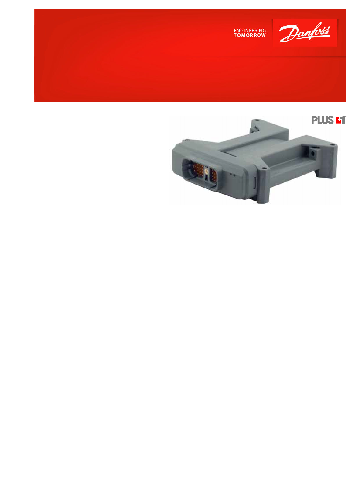
PLUS+1® Controllers
MC038-010 and MC038-012
Mobile machine management
Danfoss PLUS+1® controllers are elements of the
flexible, powerful, expandable, and affordable family
of mobile machine management products. These
devices are general-purpose controllers that are
equally suited for use as a member of a distributed
machine control system, with intelligence in every
node, or as a stand-alone controller.
Product highlights
Both controllers employ a Digital Signal Processor
(DSP), providing the controller with extremely fast
single cycle processing speed and 128K internal flash.
Application development
The MC038-012 employs an application key that
enables the use of Danfoss developed PLUS+1
GUIDE machine control solutions. The same PLUS+1
GUIDE HWD file is used with both controllers.
Users develop MC038-010 and MC038-012
applications with PLUS+1® GUIDE. This Microsoft
Windows based development environment features a
user-friendly, field proven, icon-based graphical
programming tool, application downloader, and
service/diagnostic tool.
Features
•
User-programmable with PLUS+1
GUIDE
•
Support of unlimited read-write FRAM,
2MB flash vault memory
•
38 pins: (1) DEUTSCH DRC connector
•
32 bit fixed-point DSP running at 150
MHz
•
12 bit analog-to-digital converter
•
15 inputs
•
13 outputs
•
9 to 36 VDC power supply, monitored
internally
®
®
•
2 CAN 2.0 B ports, the fixed range
analog input can be configured as the
shield pin
•
1 independent ECU power supply, 6 V
to 36 VDC, and regulated internally
•
3 independent power supplies for
powering output pins, 9 to 36 V
•
1 CAN 2.0B port. The fixed range analog
(AIN/CAN Shield) pin may be configured
as a shield pin
®
•
5 VDC power supply for external sensors
rated at 150 mA, monitored and
regulated internally
•
DC
DC
2 LEDs under application software
control
•
CE compliant
©
Danfoss | August 2018 11051653 | AI00000044en-US0301 | 1
Page 2
Data Sheet
MC038-010 and MC038-012
15 Inputs
•
(3 universal (DIN/AIN/FreqIN) that are user-defined as either:
Analog: with configurable ranges 0 to 5.25 VDC (with over range protection) or 0 to 36 V
‒
Digital: pull up (5 VDC), pull down (0 VDC) or pull to center (2.5 VDC)
‒
Frequency (timing): 1 Hz to 10 kHz
‒
•
(2) digital (DIN) configurable as pull up (5 VDC), pull down (0 VDC)
•
(9) digital/analog (DIN/AIN) that are user-defined as either:
Digital: pull up (5 VDC), pull down (0 VDC) or pull to center (2.5 VDC)
‒
Analog: 0 to 5.25 VDC or 0 to 36 V
‒
•
(1) fixed range analog (AIN/CAN shield)0 to 5.25 VDC or CAN shield pin
13 Outputs
•
(2) DOUT (2 A) configurable as source only
•
(3) HDOUT (6 A) configurable as source only
•
(3) HPWMOUT/DOUT (6 A), configurable as source only
•
(4) HPWMOUT/DOUT (10 A) configurable as source only, can be used as bi-directional pairs, (see Dimensions and Pin Assignments,
back page for pair assignments)
•
(1) HPWMOUT/DOUT (10A) configurable as source only
•
Outputs are powered by three independent power supply pins (see Dimensions and Pin Assignments, back page for output pin
power supply assignments and maximum allowable current per power supply pin)
•
All PWM outputs operate as open loop. The output is a constant voltage.
DC
DC
Comprehensive technical literature is online at www.danfoss.com
Characteristics
Specifications
Supply voltage 9 to 36 V
Operating temperature (ambient) –40 °C to +70 °C [–40 °F to +158 °F]
Storage temperature –40 °C to +85 °C [–40 °F to +185 °F]
Programming temperature 0 °C to +70 °C [+32 °F to +158 °F]
IP rating (with mating connector attached) IP 67
EMI/RFI rating 100 V/M
Weight 0.53 kg [1.16 lb]
Vibration IEC 60068-2-64
Shock IEC 60068-2-27 test Ea
Max. current, sourcing 70 A
Max. current, sinking 25 A
Max. current, power pins: C1-P36, C1-P37, C1-P38 25 A per pin
DC
2 | © Danfoss | August 2018 11051653 | AI00000044en-US0301
Page 3

47.1
51.6
193.8
159.7
144.5
114.4
147.5
35.7
139.11
32.4
C
C
35
37
29 34
13
3661
38
22
Data Sheet
MC038-010 and MC038-012
Dimensions and pin assignments
Mounting dimensions in mm
Caution
PCB damage may occur.
To prevent damage to the module all module power supply + pins
must be connected to the vehicle power supply to support
advertised module maximum output current capacity. DO NOT
use module power supply + pins to supply power to other
modules on a machine.
Caution
Warranty will be voided if device is opened.
Device is not field serviceable. Do not open the device.
Pin connector
Pin Function Pin Function
C1-P1 CPU power ground - C1-P20 DIN/AIN
C1-P2 CPU power supply + C1-P21 HPWM/DOUT (6A-Pwr =
C1-P37, source only)
C1-P3 CAN0 + C1-P22 HPWM/DOUT (10A-Pwr =
C1-P37, source only)
C1-P4 CAN0 - C1-P23 DOUT (2A-Pwr = C1-P38,
source only)
C1-P5 AIN/CAN shield C1-P24 DIN/AIN
C1-P6 DIN C1-P25 DIN/AIN
C1-P7 DIN C1-P26 DIN/AIN
C1-P8 5 VDC sensor power + C1-P27 DIN/AIN
C1-P9 Sensor power ground - C1-P28 DOUT (2A-Pwr = C1-P38,
source only)
C1-P10 DIN/AIN/FreqIN C1-P29 DOUT (2A-Pwr = C1-P38,
source only)
C1-P11 DIN/AIN/FreqIN C1-P30 DOUT (6A-Pwr = C1-P38,
source only)
C1-P12 DIN/AIN/FreqIN C1-P31 DOUT (6A-Pwr = C1-P38,
source only)
C1-P13 HPWM/DOUT (10A-Pwr =
C1P37, pair with C1-P15)
C1-P14 DIN/AIN C1-P33 HPWM/DOUT (6A-Pwr =
C1-P15 HPWM/DOUT (10A-Pwr =
C1P37, pair with C1-P13)
C1-P16 HDOUT (6A-Pwr = C1-P38,
source only)
C1-P17 DIN/AIN C1-P36 Output power supply +
C1-P18 DIN/AIN C1-P37 Output power supply +
C1-P19 DIN/AIN C1-P38 Output power supply +
C1-P32 DOUT (6A-Pwr = C1-P38,
source only)
C1-P36, source only)
C1-P34 HPWM/DOUT (10A-Pwr =
C1-P36, pair with C1-P29)
C1-P35 Output power ground -
Use care when wiring mating connector. Pinouts are for device
pins.
©
Danfoss | August 2018 11051653 | AI00000044en-US0301 | 3
Page 4

Product part number
MC038-010 11035917
MC038-012 11076594
Related products part numbers
CG150 CAN/USB Gateway 11153051
DEUTSCH mating connector
bag assembly
11027919
(16 to 20 AWG)
PLUS+1® GUIDE Professional 11179523
Comprehensive information
MC0XX-0XX Controller Family Technical Information, 520L0719
MC038-010 and MC038-012 Application Program Interface (API) document
Danfoss can accept no responsibility for possible errors in catalogues, brochures and other printed material. Danfoss reserves the right to alter its products without notice. This also applies to products
already on order provided that such alterations can be made without changes being necessary in specifications already agreed.
All trademarks in this material are property of the respective companies. Danfoss and the Danfoss logotype are trademarks of Danfoss A/S. All rights reserved.
4 | © Danfoss | August 2018 11051653 | AI00000044en-US0301
 Loading...