

Page 1

Page 2

01.02.00 © Danfoss| Energy Meters| 2018.02| 2
1 Basic information .................................................................................................... 4
1.1 The physical layer ............................................................................................. 4
1.2 Wake up process and baud rate changes (IR) ....................................................... 4
1.3 Baud rate changes ............................................................................................ 4
1.3.1 Wait time before reply after correct message reception .................................... 5
1.4 Data Link layer (DLL) ......................................................................................... 5
1.4.1 C field (Control field, Function field) – Field size 1 byte ................................... 5
1.4.2 A Field (Address Field) – 1 byte .................................................................... 6
1.4.3 L Field – 2 fields with a size of 1 byte ............................................................ 7
1.4.4 CS field – 1 byte ......................................................................................... 7
1.5 Combined Transportation and application layer ..................................................... 8
1.5.1 CI Field (Control information field) ................................................................ 8
1.5.2 Long header ............................................................................................... 9
1.5.3 Status byte and error handling ................................................................... 10
1.5.4 DIF & VIF configuration of data records ........................................................ 11
1.6 The standard read out ..................................................................................... 13
2 Communication process ......................................................................................... 16
2.1 M-Bus EN 13757 data frames ........................................................................... 16
2.2 Pulse readout ................................................................................................. 17
2.3 Application reset ............................................................................................. 17
2.4 Send/Confirm procedures available using the Danfoss Meter ................................. 21
2.4.1 SND_NKE ................................................................................................. 21
2.4.2 SND_UD .................................................................................................. 22
2.4.3 REQ_UD2 ................................................................................................. 34
2.4.4 RSP_UD ................................................................................................... 35
Annex A ..................................................................................................................... 36
Page 3
01.02.00 © Danfoss| Energy Meters| 2018.02| 3
Identify the needed telegrams from the EN13757 standard and determine how to implement
the SonoSelect 10 and SonoSafe 10 communication protocol into an M-Bus telegram. This
document contains the description the M-Bus protocol implemented for SonoSelect 10 and
SonoSafe 10. The M-Bus protocol will follow the EN13757 standard.
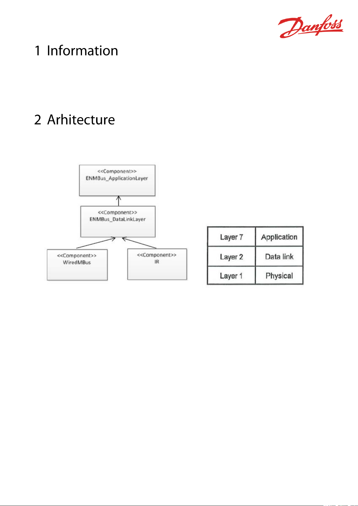
According to the software architecture of the SonoSelect 10 and SonoSafe 10 the
communication shall be split into three layers.
Figure 1 - OSI model and architecture of HM
The M-Bus protocol for the IR and Wired communication will be identical and therefore these
two components will share the same data-link and application layer. The M-Bus will only
support physical, data-link and combined transportation and application layer. The other layers
stated in EN13757-3 are optional and will not be part the wired M-Bus implementation of the
SonoSelect 10 and SonoSafe 10. According to the EN13757-1 standard the transportation layer
must be handled in an Application Layer.
Page 4
01.02.00 © Danfoss| Energy Meters| 2018.02| 4
The physical layer is a serial asynchronous half-duplex communication.
The meter act as a slave and each character communicated consist of 11-bits as shown below:
• 1 start bit (‘Space’)
• 8 data bits
• 1 parity bit (even)
• 1 stop bit (‘Mark’)
The master issues a request and the slave respond.
Since the optical interface uses the EN 13757-2 protocol, a wake-up message can be sent after
every ¡die time of> 330 bit times to the heat meter. The wake up message consists of zeroes
and ones alternating at the desired baud rate for a duration of (2,2 ± 0,1) s. After an idle time
of 33 bit times to 330 bit times, the communication can start.
The baud rate requirements from EN13757-3 are as follows:
• The IR supports 2400 and 4800 Baud
• The wired baud rate supports 300, 2400, 4800 and 9600
• Baud rate is kept after reset of device.
Meters with hardware issue 5 have auto baudrate detection on both the IR and Wired M-Bus
interface.
Maximum data records:
The maximum data record length is 235 bytes
Wildcard search (Secondary address)
Secondary address is found by using a wildcard search (CI = 52H). The top positions are run
through in ten selections from 0-9 (0FFFFFFF – 9FFFFFFF). If slave is found it answers with an
ACK and the master requests the full secondary address which is returned in a RSP_UD from
the slave. Any collisions and the master vary the next positions and hold the existing one.
Page 5

01.02.00 © Danfoss| Energy Meters| 2018.02| 5
After reception of valid telegram the slave has to wait between 11bit time and (330 bit times +
50ms) before answering (EN1434-3)
Baud rate
Min.
Max.
300 Baud
36,7ms
1150ms
2400 Baud
4,6ms
187,5ms
4800 Baud
2,3ms
118,8ms
9600 Baud
1,2ms
84,4ms
In this section the data link layer is described. One of the frames used in the M-Bus standard is
shown below. The other M-Bus frames can be found in section 4.1.
The function field specifies the direction of the data flow and has various additional tasks in
both calling and replying directions but many of these are optional and therefore not
implemented.
Bit Number
7 6 5 4 3 2 1
0
Calling
direction
0 1 FCB
FCV
F3
F2
F1
F0
Reply
Direction
0
0
ACD
DFC
F3
F2
F1
F0
• Bit7 reserved for future use.
• Bit6 specifies the direction of the data flow. If it is set to 1 the communication has the
direction Master to slave and vice versa if it is set to 0.
• FCB The slave do not act on this bit and is always sending new data.
• FCV The slave ignores this bit.
• DFC (data flow control) Not supported must be 0.
• ACD (Access demand) Not supported must be 0.
Page 6
01.02.00 © Danfoss| Energy Meters| 2018.02| 6
• Control field F3-F0 the control field code tells the function or action of the message.
The control field has 7 predefined control field shown below.
Name
C field binary
C field
(HEX)
Telegram
Description
SND_NKE
0100 0000
40
Short frame
Initialization of slave
SND_UD
01F1 0011
53/73
Long/Control
Send user data to slave
REQ_UD1
01F1 1010
5A/7A
Short frame
Request class 1 data
REQ_UD2
01F1 1011
5B/7B
Short frame
Request class 2 data
REQ_SKE
0100 1001
49
Short frame
Status request
RSP_SKE
0000 1011
0B
Short frame
Status data, slave to
master
RSP_UD
00AD 1000
08
Long/Control
Data transfer from slave
to master after request
REQ_UD1 telegrams are answered with ACK because the Alarm protocols are not supported.
The primary address of the meter can be set to a value from 0-250. The default primary
address is part of the serial number (red letters: ssssswwNNyyww) and is always a number
from 00-99. To change the primary address either use the SonoApp or M-Bus command
described later in this document.
Point-to-point addressing (0xFE) is intended for communication using the infrared eye or for
network with only one slave (used for test of network with one slave).
Broadcast (0xFF) is used to communicate across the network to all the slaves e.g. to set a new
baud rate on all slaves at the same time. Be aware that no acknowledge byte is replied from
the slave in broadcast mode.
The secondary address can be used to select a slave. This slave can then afterwards be
contacted using the primary address FDH. All slaves have an unique secondary address which
ensures only a single slave answers.
Addressing Form
Slave Addressing
Primary addressing
0-250
Secondary
addressing and
selected slave
253 (FDH)
Point-to-Point
addressing
254 (FEH)
Broadcast
255 (FFH)
Page 7
01.02.00 © Danfoss| Energy Meters| 2018.02| 7
The Length Field (L Field) defines the number of bytes (expressed in hex value) of the Active
Data making up the telegram, plus 3 bytes for the C, A and Cl Fields.
This field is always transmitted twice in Long Telegrams (RSP_UD) see 4.1.
The Checksum (CS Field) serves to recognize transmission and synchronization faults. The
checksum is calculated on the Active Data making up the telegram, plus 3 bytes for the C, A
and Cl Fields. All bytes are added together in a 8 bit unsigned integer, which means that when
the value gets larger than FFh it will wrap around and start all over.
Page 8
01.02.00 © Danfoss| Energy Meters| 2018.02| 8
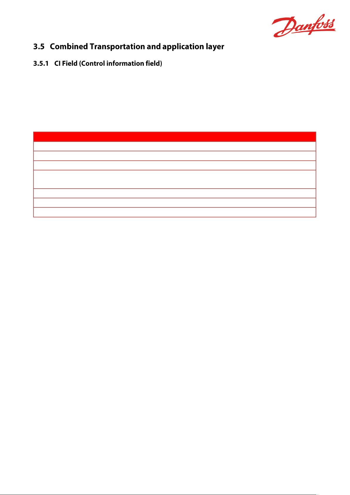
The CI-Field declares the transportation direction and the Application protocol (if exists). The
CI-Field declares also which type of Transport Layer (“None”, “Short” and “Long” header) is
applied.
In the SonoSelect/Safe meters with wired M-Bust the long header (0x72) is always used.
The SonoSelect/Safe meters supports the following CI-Fields.
CI-field (HEX)
Direction
50
Application reset
51
Data send to device
52
Slave select (no header)
72
The telegram contains data for the master
with long header
B8
Set baud rate 300 (only wired M-Bus)
BB
Set Baud Rate to 2400
BD
Set Baud Rate to 9600
Page 9
01.02.00 © Danfoss| Energy Meters| 2018.02| 9
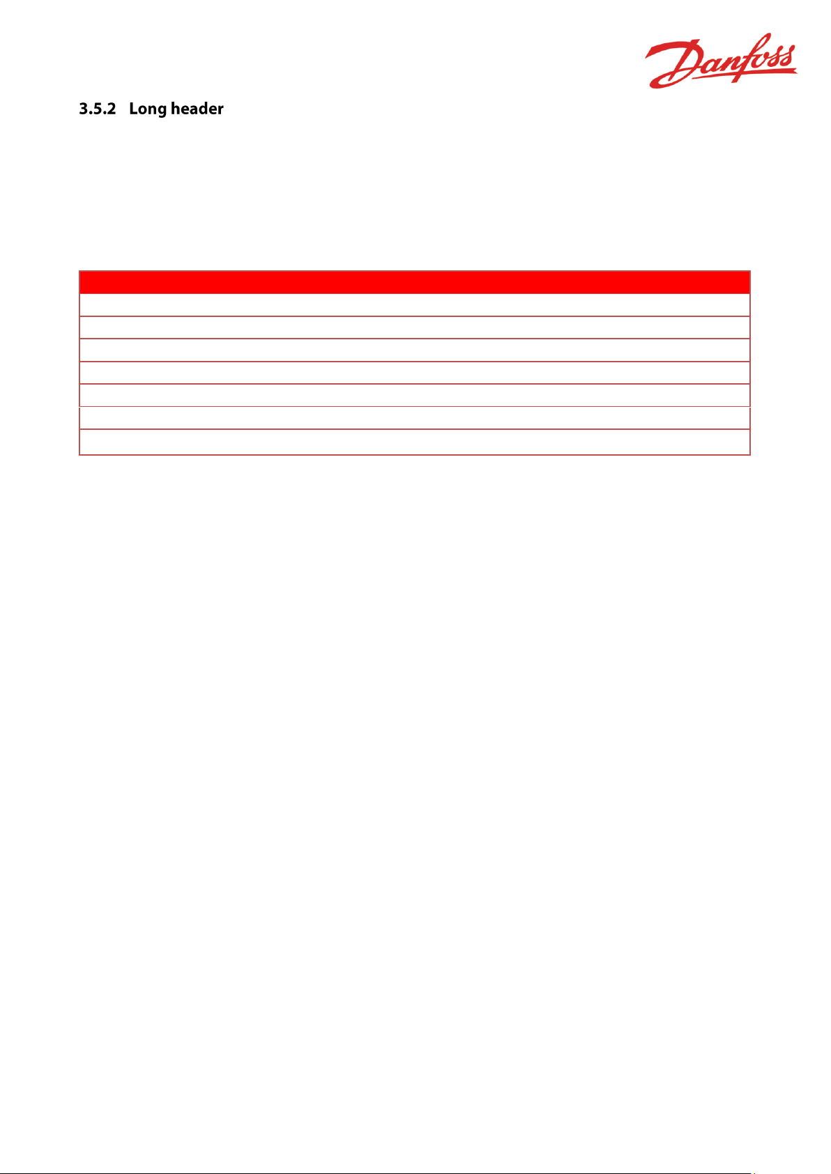
The long header contains 12 bytes which is used to identify the Meter, hold track of new or old
message and to apply encryption.
The encryption is not currently available for wired Danfoss Meters which means the
configuration field always is 0000H.
The 12 byte long header is shown in the table below:
Byte Nr.
Size(Byte)
Value(Hex)
Description
1-4
4
xx xx xx xx
Meter identification number
5-6 2 D310
Manufacturer’s ID (DFS Danfoss 10D3h)
7 1 xx
Version number firmware (00-FF)
8 1 04/0C
Medium: Heat outlet/inlet
9 1 xx
Access Number (00-FF-> 00)
10 1 xx
Status
11-12 2 0000
Configuration
The identification number (secondary address) is a non-changeable (according to OMS)
number in between 00000000 and 99999999. The identification number is part of the Danfoss
Meters serial number and is unique. (In installations with other meters where same address is
present the address can be change with SonoApp or M-Bus command shown later)
The secondary address is derived from the serial number. The serial number has the following
format:
ssssswwNNyyww
The secondary address has the following format
ywwsssss
The manufactures ID is used to identify the manufacture of the Meter. Each manufacture has a
flag consisting of three capital letters which can be combined to two bytes according to
EN13757-3. The Danfoss manufacture flag is DFS (10D3h) and this flag is always part of the
long header.
The version number is used to identify if the meter is of type:
• SonoSafe (0x01)
• SonoSelect (0x02).
The medium byte identifies the flow sensor installation of the Meter and has two settings for
each meter type:
• Heat Inlet meters (supply 0x0C)
• Heat Outlet meters (return 0x04).
• Cooling Meter (Volume measured at return temperature: outlet)
Page 10
01.02.00 © Danfoss| Energy Meters| 2018.02| 10
• Cooling Meter (Volume measured at flow temperature: inlet)
• Combined meter
• Water meter (For pulse readout only)
The Access Number has an unsigned binary coding and is incremented (modulo 256) by one
after each RSP-UD is send from the slave.
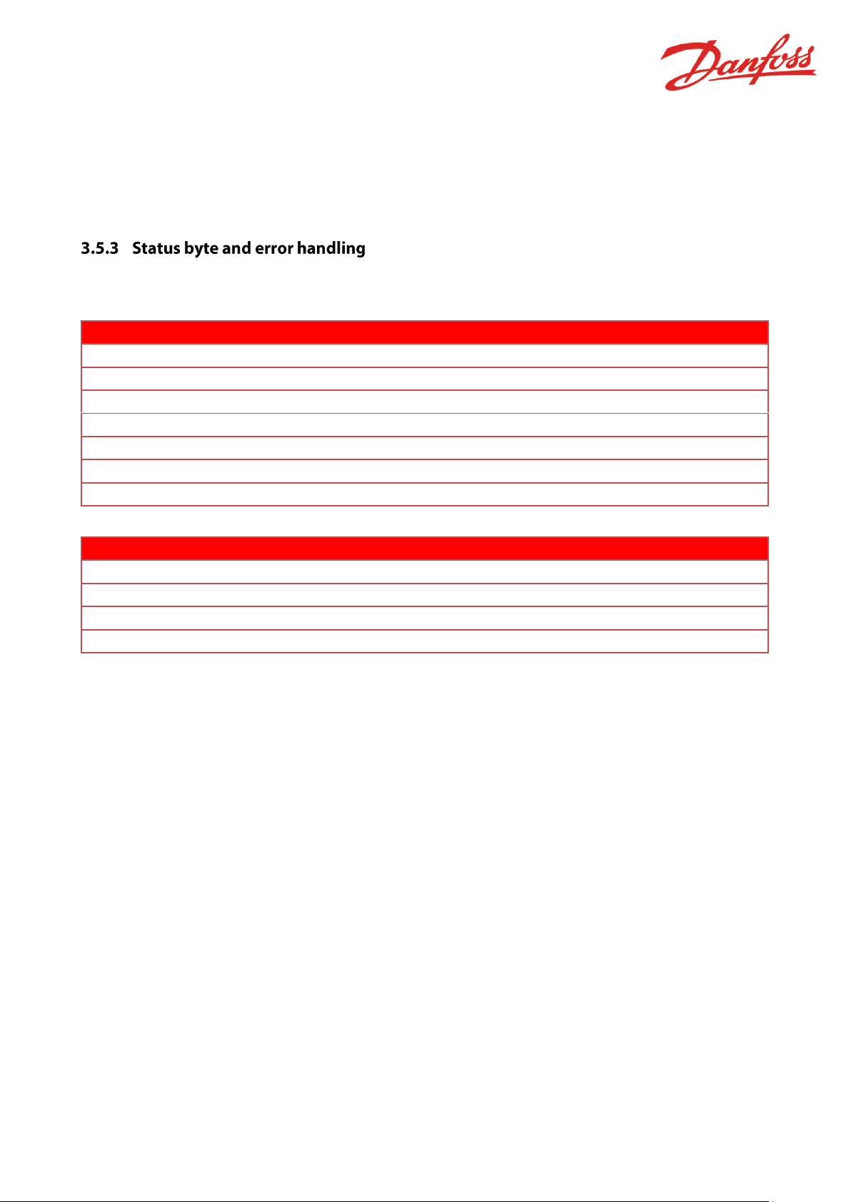
The status byte is used to indicate different potential errors in the Meter. The errors are stated
in the table below:
Bit
Meaning with bit set
Significance with bit not set
0,1
See table 5
See table 5
2
Power Low
Power Ok
3
Permanent error
No Permanent error
4
Temporary error
No Temporary error
5
Specific to manufacturer
Specific to manufacturer
6
Specific to manufacturer
Specific to manufacturer
7
Specific to manufacturer
Specific to manufacturer
Status bit 1 bit 0
0 0
No Error
0 1
Application busy
1 0
Any application error
1 1
Abnormal condition/alarm
The status bit shall be used in this meaning:
Power low:
Warning – The bit “Power Low” is set only to signal interruption of external power supply or
end of battery life time
Permanent error:
Failure – The bit “Permanent error” is set only if the meter signals a fatal device error which
requires a service action.
Temporary error:
Warning – The bit “Temporary error” is set only if the meter signals a slight error condition
which not immediately requires a service action. This could be an error which may later
disappear.
Any application error:
The application error shall be used to communicate a failure during the interpretation or
execution of a received command, e.g. a message which could not be decrypted.
Page 11
01.02.00 © Danfoss| Energy Meters| 2018.02| 11
Abnormal conditions:
Shall be used if a correct working application detects an abnormal behavior like a permanent
high flow.
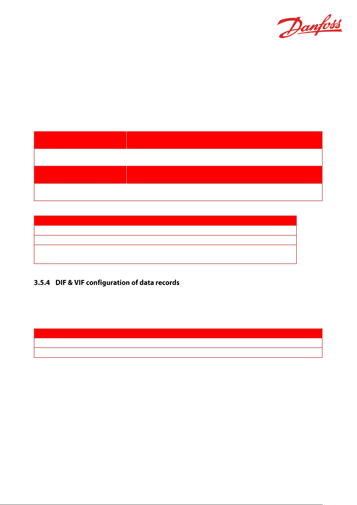
The most critical active E-number (Error shown in the display) is sent as the status byte. The
most critical error is E1 and least critical is E32.
Below is a table showing the bit pattern.
ENumber
E1
E2
E3
E4
E5
E6
E7
E8
E9
E10
E11
E12
E13
Hex
code
0x08
0x10
0x28
0x04
0x24
0x30
0x50
0x70
0x90
0xB0
0xD0
0xF0
0x48
ENumber
E14
E15
E16
E17
E18
E32
Hex
code
0x40
0x44
0x60
0x62
0x13
0x92
Error type
E number
Power Low
E4, E5, E15
Permanent error
E1, E3, E13
Temporary error
E2, E6, E7, E8, E9, E10, E11, E12, E14, E16,
E17, E18, E32
The application layer contains the data sent from the slave to the master or vice versa.
Every data record sent which is not manufacture specific have the following data record header
(DRH)
Data Information Block (DIB)
Value Information Block (VIB)
DIF
DIFE
VIF
VIFE
Data
1 Byte
0-10Byte(s)
1 Bytes
0-10 Byte(s)
0-n Bytes
Page 12

01.02.00 © Danfoss| Energy Meters| 2018.02| 12
The Data Information Block (DIB) contains at least one DIF but can be extended by 10 DIFE if
needed.
The DIFs supported by the Danfoss Meters:
Bit
Name
Description
7
Extension Bit
Specifies if a DIFE byte follows:
0 = No
1 = Yes
6
LSB of Storage Number
0 if log is not send
5-4
Function Field
Specifies the kind of value
00 = instantaneous value
01 = Maximum value
10 = Minimum Value
11 = Value during error state
3-0
Data Field
Length and Coding of Data:
0001 (0x01): 8 Bit Integer
0010 (0x02): 16 Bit Integer
0011 (0x03): 24 Bit Integer
0100 (0x04): 32 Bit Integer
0110 (0x06): 48 bit Integer (only for record)
0111 (0x07): 64 Bit Integer (only for record)
1001 (0x09): 2 digit BCD
1010 (0x0A): 4 digit BCD
1011 (0x0B) 6 digit BCD
1100 (0x0C): 8 digit BCD
1101 (0x0D): Variable length (Only for TX)
1111 (0x0F): Manufacture Specific Data
The DIFE supported by Danfoss Meters:
Bit
Name
Description
7
Extension Bit
Specifies if a DIFE byte follows:
0 = No
1 = Yes
6
Unit
Specifies if it is pulse counter or cooling value
5-4
Tariff
Used oC*m^3 records
3-0
Storage number
0000 (only used for logs)
The DIFE is used for selection of pulse 1 and pulse 2 counters. If first DIFE has the unit set to
1, it is pulse counter 1 and if the unit is set in the second DIFE, it is pulse counter 2 (see
4.4.2.7). The DIFE unit 3 is used for cooling records (Energy, Volume, Max Flow, Max Power).
The DIFE storage number is used to show the log values and which type of log there are sent.
The storage number 1 & 2 are used for year log 1 and 2.
The storage number from 3-26 is used for month log 1-24.
Page 13

01.02.00 © Danfoss| Energy Meters| 2018.02| 13
The Value Information Block (VIB) contains minimum 1 VIF but can be extended by 10 VIFE if
needed (Danfoss Meters support only one VIF and up to 4 VIFEs).
The coding of the VIF is:
Bit
Name
Description
7
Extension Bit
Specifies if a VIFE byte follows the VIF
6-0
Value Information
Contains information for a single value.
Unit and multiplier of each data record
The coding of the VIFE is:
Bit
Name
Description
7
Extension Bit
Specifies if a VIFE byte follows the VIFE
6-0
Value Information
Contains information for a single value.
Unit, multiplication, etc.
• Energy
• Volume
• Flow rate
• Power
• Forward temperature
• Return temperature
• Difference temperature
• External temperature
• Current time
• Operation hours
• Hour Counter OK
Page 14

01.02.00 © Danfoss| Energy Meters| 2018.02| 14
The VIF & VIFE combination used in the SonoSelect/Safe meters:
VIF (HEX)
VIFE (HEX)
Description
Unit
00
-
Energy
0.000001 kWh
01
-
Energy
0.00001 kWh
02
-
Energy
0.0001 kWh
03
-
Energy
0.001 kWh
04
-
Energy
0.01 kWh
05
-
Energy
0.1 kWh
06
-
Energy
1 kWh
03
-
Energy
0.000001 MWh
04
-
Energy
0.00001 MWh
05
-
Energy
0.0001 MWh
06
-
Energy
0.001 MWh
07
-
Energy
0.01 MWh
FB
00
Energy
0.1 MWh
FB
01
Energy
1 MWh
0B
-
Energy
0.000001 GJ
0C
-
Energy
0.00001 GJ
0D
-
Energy
0.0001 GJ
0E
-
Energy
0.001 GJ
0F
-
Energy
0.01 GJ
FB
08
Energy
0.1 GJ
FB
09
Energy
1 GJ
FB
8C 74
Energy
0.000001 GCal
FB
8C 75
Energy
0.00001 GCal
FB
0C
Energy
0.0001 GCal
FB
0D
Energy
0.001 GCal
FB
0E
Energy
0.01 GCal
FB
0F
Energy
0.1 GCal
FB
8F 77
Energy
1 GCal
90
70
Volume
0.000000000001 m3
(full resolution pico m
3)
10
-
Volume
0.000001 m3
11
-
Volume
0.00001 m3
12
-
Volume
0.0001 m3
13
-
Volume
0.001 m3
14
-
Volume
0.01 m3
15
-
Volume
0.1 m3
16
-
Volume
1 m
3
98
70
Mass
0.000000001 kg
38
-
Flow rate
0.001 l/h
39
-
Flow rate
0.01 l/h
Page 15

01.02.00 © Danfoss| Energy Meters| 2018.02| 15
3A
-
Flow rate
0.1 l/h
3B
-
Flow rate
1 l/h
3B
-
Flow rate
0.001 m3/h
3C
-
Flow rate
0.01 m3/h
3D
-
Flow rate
0.1 m3/h
3E
-
Flow rate
1 m3/h
2B
-
Power
0.001 kW
2C
-
Power
0.01 kW
2D
-
Power
0.1 kW
2E
-
Power
1 kW
58 - Forward temperature
0.001 °C
59 - Forward temperature
0.01 °C
5A - Forward temperature
0.1 °C
5B - Forward temperature
1 °C
5C - Return temperature
0.001 °C
5D - Return temperature
0.01 °C
5E - Return temperature
0.1 °C
5F - Return temperature
1 °C
64 - External temperature
0.001 °C
65 - External temperature
0.01 °C
66 - External temperature
0.1 °C
67 - External temperature
1 °C
60 - Difference temperature
0.001K
61 - Difference temperature
0.01K
62 - Difference temperature
0.1K
63 - Difference temperature
1K
FD
09
Device type
Meter type
FD
3A
Without unit
FWChecksum
26 - Hour Counter OK
1h
22 - Factory hour counter hours
1h
6C
-
Date
Date (Type G)
6D
Current time
Date and time (type F)
A6
18
Hour counter Alarm
1h
FD
70
Battery change date
Date (Type G)
FD
6C
Operating time battery
hours
FD
74
Remaining battery life time
days
EC
7E
Next accounting date
Date (type G)
FD
BA 70
Multiplicative correction factor
10^(-6)
Page 16

01.02.00 © Danfoss| Energy Meters| 2018.02| 16
There are 4 different data frame formats (See table below) available for communicating
between the master and slave using the EN 13757-3 M-Bus standard and these are supported
by the Danfoss Meters.
• Single character frame, slave uses this frame to send an acknowledgement for the
data received from the master.
• Short frame which is used to e.g. make a data request master to slave
• Control frame is used to e.g. change the baud rate of a slave
• Long frame is used to e.g. change which data the slave should return and is used as
response frame for the slave containing the data requested by the master.
M-Bus is an asynchronous serial bit transmission in half-duplex mode, which means that it is
only possible to transmit in one direction at a time. The standard way of communicating is to
send a SND which the slave will answer with an acknowledgement (ACK) or a request (REQ)
which the slave will respond on with a RSP.
The communication process will follow one of the following two kinds of transmissions:
Master send / Slave confirm : SND/ACK
Master request / Slave respond : REQ/RSP
The standard communication between an M-Bus master and an M-Bus slave is:
Command
Master
Slave
Deselect old slave
SND_NKE
ACK
Select new slave
SND_UD
ACK
Request data
REQ_UD2
RSP_UD
Page 17

01.02.00 © Danfoss| Energy Meters| 2018.02| 17
The meter supports up to two pulse input when a module is inserted. Each of the pulse
interfaces can be configured by SonoApp, to obtain a separate secondary address in the meter.
The configuration of the Pulse interface is done using SonoApp.
It is possible to readout each of these pulse meters individually using the RSP_UD command.
The meters returns an accumulated volume register and a month log record with accumulated
volume and a timestamp.
The pulse addresses only support readout (+ Slave select and SND_NKE) and not the rest of
the commands in this document. Primary addressing is also not supported to obtain the pulse
values.
4.3.1.1 Application reset
The master is capable of changing the current readout temporary, using the command in
4.4.2.9. The Application Reset, resets the access number to 0 and returns the readout to a
normal standard readout telegram. The Application reset telegram is below:
Field name
# of
Bytes
Value
Description
Layer
Start
1
68H
Start of Frame
Data Link Layer
(DLL)
L Field
1
04H
2nd Start to Checksum
L Field
1
04H
2nd Start to Checksum
Start
1
68H
Start of Frame
C Field
1
73H
SND_UD
A Field
1
FDH
Primary Address
CI 1 50H
Application reset byte
TPL
Reset byte
1
00H
Application reset subcode
Checksum
1
C0H
Checksum
DLL
End of Frame
1
16H
Answer of the Slave: E5h
The SonoSelect and SonoSafe with the FW 01.03 or above supports multiple application reset
telegrams, which changes the outputted registers until another reset arrives.
If the meter is a Combined Meter (Heat and Cooling), the telegrams contains both the heat
and cooling accumulated registers.
Page 18

01.02.00 © Danfoss| Energy Meters| 2018.02| 18
The M-Bus standard supports the following application resets:
Application reset subcode
Telegram data
0x00
Standard Danfoss output
(Diagnosis data will only
be part of this telegram)
Accumulated Energy (heat and cooling for combined)
Accumulated Volume (heat and cooling for combined)
Flow Rate
Power
Supply Temperature
Return Temperature
Difference Temperature
External Temperature (Enclosure)
Current Time
Hour counter factory (operating hours since factory)
Hour counter ok (Operating hours without error)
0x10
User Data
Accumulated Energy (heat and cooling for combined)
Accumulated Volume (heat and cooling for combined)
Current Time
Hour counter factory (operating hours since factory)
Month log 1 (newest year log) (storage number = 3)
• Date
• Accumulated Energy
• Accumulated Volume
• Optional (max power and flow)
Year log 1 (newest year log) (storage number = 1)
• Date
• Accumulated Energy (heat and cooling for combined)
• Accumulated Volume (heat and cooling for combined)
• Optional (max power and flow)
0x20
Simple billing
Accumulated Energy (heat and cooling for combined)
Accumulated Volume (heat and cooling for combined)
Flow Rate
Power
Supply Temperature
Return Temperature
Difference Temperature
Hour counter factory (operating hours since factory)
Current Time
0x30
Enhanced billing,
historical energy registers
(Combined meter will
only return 6 months and
1 year)
Accumulated Energy (heat and cooling for combined)
Accumulated Volume (heat and cooling for combined)
Year log 1 (newest year log) (storage number = 1)
• Date
• Accumulated Energy (heat and cooling for combined)
Year log 2 (storage number = 2)
• Date
Page 19

01.02.00 © Danfoss| Energy Meters| 2018.02| 19
Combined meter has both
cooling and heat energy
• Accumulated Energy
Month log 1 (newest month log) (storage number = 3)
• Date
• Accumulated Energy (heat and cooling for combined)
Month log 2 (storage number = 4)
• Date
• Accumulated Energy (heat and cooling for combined)
Month log 3 (storage number = 5)
• Date
• Accumulated Energy (heat and cooling for combined)
Month log 4 (storage number = 6)
• Date
• Accumulated Energy (heat and cooling for combined)
Month log 5 (storage number = 7)
• Date
• Accumulated Energy (heat and cooling for combined)
Month log 6 (storage number = 8)
• Date
• Accumulated Energy (heat and cooling for combined)
Month log 7 (storage number = 9)
• Date
• Accumulated Energy
Month log 8 (storage number = 10)
• Date
• Accumulated Energy
Month log 9 (storage number = 11)
• Date
• Accumulated Energy
Month log 10 (storage number = 12)
• Date
• Accumulated Energy
Month log 11 (storage number = 13)
• Date
• Accumulated Energy
Month log 12 (storage number = 14)
• Date
• Accumulated Energy
0x40
Enhanced billing,
historical volume
registers
(Combined meter will
only return 6 months and
1 year)
Accumulated Energy
Accumulated Volume
Year log 1 (newest year log) (storage number = 1)
• Date
• Accumulated Volume (heat and cooling for combined)
Year log 2 (storage number = 2)
• Date
• Accumulated Volume
Page 20

01.02.00 © Danfoss| Energy Meters| 2018.02| 20
Combined meter has both
cooling and heat volume
Month log 1 (newest month log) (storage number = 3)
• Date
• Accumulated Volume (heat and cooling for combined)
Month log 2 (storage number = 4)
• Date
• Accumulated Volume (heat and cooling for combined)
Month log 3 (storage number = 5)
• Date
• Accumulated Volume (heat and cooling for combined)
Month log 4 (storage number = 6)
• Date
• Accumulated Volume (heat and cooling for combined)
Month log 5 (storage number = 7)
• Date
• Accumulated Volume (heat and cooling for combined)
Month log 6 (storage number = 8)
• Date
• Accumulated Volume (heat and cooling for combined)
Month log 7 (storage number = 9)
• Date
• Accumulated Volume
Month log 8 (storage number = 10)
• Date
• Accumulated Volume
Month log 9 (storage number = 11)
• Date
• Accumulated Volume
Month log 10 (storage number = 12)
• Date
• Accumulated Volume
Month log 11 (storage number = 13)
• Date
• Accumulated Volume
Month log 12 (storage number = 14)
• Date
• Accumulated Volume
0x50
Instant values
Accumulated Energy (heat and cooling for combined)
Accumulated Volume (heat and cooling for combined)
Flow Rate
Power
Supply Temperature
Return Temperature
Difference Temperature
External Temperature (Enclosure)
Current time
Page 21

01.02.00 © Danfoss| Energy Meters| 2018.02| 21
Hour counter factory (operating hours since factory)
Hour counter ok (Operating hours without error)
Hour counter alarm (Operating hour with error)
0x90
Testing
High resolution Accumulated Energy
(heat and cooling for combined)
High resolution Accumulated Volume
(heat and cooling for combined)
Flow Rate
Power
Supply Temperature
Return Temperature
Difference Temperature
This command is used after an interrupts or as a beginning of communication. A slave selected
for secondary addressing is deselected, if a SND_NKE to address 253 or a command to a nonmatching secondary address is received.
The selected slave acknowledges the deselection if a SND_NKE is received on address 253.
Field name
# of
Bytes
Value
Description
Layer
Start
1
10H
Start of short frame
Data Link
Layer (DLL)
C Field
1
40H
SND_NKE
A Field
1
FDH
Primary Address
Checksum
1
4AH
Checksum
End of Frame
1
16H
Answer of the Slave: E5h
Page 22

01.02.00 © Danfoss| Energy Meters| 2018.02| 22
These telegrams are used to send data from the master to the slave. The slave confirms any
correct receptions (requires correct address, primary or secondary) of these telegrams also if
the command received is not supported.
4.4.2.1 Set primary address
This telegram changes a Meters primary address using its current primary address:
Field name
# of
Bytes
Value
Description
Layer
Start
1
68H
Start of Frame
Data Link Layer
(DLL)
L Field
1
06H
C field to Checksum
L Field
1
06H
C field to Checksum
Start
1
68H
Start of Frame
C Field
1
73H
SND_UD
A Field
1
FEH
Current Primary Address
CI Field
1
51H
Data from Master to Slave
TPL
DIF 1 01H
8-bit integer
APL
VIF 1 7AH
Change primary address
Value
1
05H
New Primary Address (address 5)
Checksum
1
42H
Checksum
DLL
End of Frame
1
16H
Answer of the Slave: E5h
Page 23

01.02.00 © Danfoss| Energy Meters| 2018.02| 23
4.4.2.2 Set secondary address
The secondary address has the following structure:
Byte Nr.
Size(Byte)
Value(Hex)
Description
1-4
4
xx xx xx xx
HM identification number
5-6 2 10D3
Manufacturer’s ID (DFS Danfoss)
7 1 xx
Version number firmware (00-FF)
8 1 04/0C
Medium: Heat
The secondary address is unique but in installations with other meter types with matching
secondary access, it is possible to change the secondary address using this command or
SonoAPP.
Field name
# of
Bytes
Value
Description
Start of Frame
1
68H
Start of control frame
Data Link Layer (DLL)
L Field
1
09H
C field to Checksum
L Field
1
09H
C field to Checksum
Start 1 68H
C Field
1
73H
SND_UD
A Field
1
FEH
Primary address (00-FA = 0-
250), FE(point to point), FD
selected slave
CI Field
1
51H
TPL
DIF 1 0CH
8 digits BCD, 4 byte
Application Layer
(APL)
VIF 1 79H
Set secondary address
New secondary
address
1
78H
Digit 7 and 8
Range: 00-99
New secondary
address
1
56H
Digit 5 and 6
Range: 00-99
New secondary
address
1
34H
Digit 3 and 4
Range: 00-99
New secondary
address
1
12H
Digit 1 and 2
Range: 00-99
Checksum
1
3BH
Checksum
DLL
End of Frame
1
16H
Stop character
The secondary address can be changed using one of the following DIF types:
• INT32
• 8 Digit BCD
• INT64 (Most data concentrators are using the INT64)
The address must in all types be entered as a BCD code. (e.g. address 12345678 is
0x12345678). The last four bytes in the INT64 will not change anything in the Meter.
Page 24

01.02.00 © Danfoss| Energy Meters| 2018.02| 24
4.4.2.3 Set Baud Rate
The Meter supports the Baud Rates 300, 2400, 4800 and 9600 (Meters with Hardware Issue 5
have auto baudrate detection).
The Meter answers with single character acknowledgement (E5h) using the old baud rate.
When the ACK is transmitted, the Meter switch to the new baud rate.
The master makes sure that the Meter has changed into the correct baud rate. To do this the
master sends a command to the Meter within 2 min of the baud rate change. If the Meter
doesn’t answer with an ACK after 3 retry, the master has to return to the old baud rate.
If the Meter doesn’t support the new baud rate it stays on the old baud rate after sending an
ACK.
The command for changing baud rate is:
Field name
# of
Bytes
Value
Description
Layer
Start
1
68H
Start of Frame
Data link Layer
(DLL)
L Field
1
03H
2nd Start to Checksum
L Field
1
03H
2nd Start to Checksum
Start
1
68H
Start of Frame
C Field
1
73H
SND_UD
A Field
1
XXH
Primary Address
CI Field
1
B8H
BBH
BCH
BDH
300 Baud
2400 Baud
4800 Baud
9600 Baud
TPL
Checksum
1
??H
Checksum
DLL
End of Frame
1
16H
Answer of the Slave: E5h
Page 25

01.02.00 © Danfoss| Energy Meters| 2018.02| 25
4.4.2.4 Slave select
To select a Meter the following command must be used:
Field name
# of
Bytes
Value
Description
Start 1 68H
Start of Frame
Data Link Layer
(DLL)
L Field
1
0BH
2nd Start to Checksum
L Field
1
0BH
2nd Start to Checksum
Start 1 68H
Start of Frame
C Field
1
73H
SND_UD
A Field
1
FDH
Use secondary address
CI Field
1
52H
TPL
Secondary
address
8
xx xx xx
xx xx xx
xx xx
Current secondary address
Checksum
1
??H
Checksum
DLL
End of Frame
1
16H
Answer of the Slave: E5h
Page 26

01.02.00 © Danfoss| Energy Meters| 2018.02| 26
4.4.2.5 Date and time
The date and time can be changed using the following SND_UD frame.
This command requires the Meter to have an access level “Installation”.
Example of setting the date and time to: 22/03/2011 08:30 (4 byte M-Bus Type F)
Field name
# of
Bytes
Value
Description
Start
1
68H
Start of Frame
Data
Link Layer
(DLL)
L Field
1
09H
C field to Checksum
L Field
1
09H
C field to Checksum
Start
1
68H
Start of Frame
C Field
1
73H
SND_UD
A Field
1
FEH
Primary Address
CI Field
1
51H
Data from Master to Slave
TPL
DIF 1 04H
32 Bit Integer
Applicatio
n
Layer
(APL)
VIF 1 6DH
Time Point (Date and time)
Date Time
1
1EH
Date & time (Type F data)
Date Time
1
28H
Date & time (Type F data)
Date Time
1
76H
Date & time (Type F data)
Date Time
1
13H
Date & time (Type F data)
Checksum
1
02H
Checksum
DLL
End of Frame
1
16H
Answer of the Slave: E5h
Page 27

01.02.00 © Danfoss| Energy Meters| 2018.02| 27
4.4.2.6 Set accounting date
The master can change the accounting date of each slave on the network. The accounting date
is send as a M-Bus type G format. The following frame sets the date to 01 june 2012.
Field name
# of
Bytes
Value
Description
Layer
Start
1
68H
Start of Frame
Data Link layer
(DLL)
L Field
1
08H
C field to Checksum
L Field
1
08H
C field to Checksum
Start
1
68H
Start of Frame
C Field
1
73H
SND_UD
A Field
1
FEH
Primary Address
CI Field
1
51H
Data from Master to Slave
TPL
DIF 1 02H
16-bit integer
Application
Layer
(APL)
VIF 1 ECH
Time Point (Date)
VIFE
1
7EH
Future value
Value
1
81H
Date (Type G)
Value
16H
Date (Type G)
Checksum
1
C5H
Checksum
DLL
End of Frame
1
16H
Answer of the Slave: E5h
Page 28

01.02.00 © Danfoss| Energy Meters| 2018.02| 28
4.4.2.7 Set Pulse counter 1 and 2
The two pulse counters accumulated values can be configured by the master. The two
telegrams below show examples:
Counter 1:
Field name
# of
Bytes
Value
Description
Layer
Start
1
68H
Start of Frame
Data Link Layer
(DLL)
L Field
1
0AH
C field to Checksum
L Field
1
0AH
C field to Checksum
Start
1
68H
Start of Frame
C Field
1
73H
SND_UD
A Field
1
FEH
Primary Address
CI Field
1
51H
Data from Master to Slave
TPL
DIF 1 84H
32 bit integer DIFE follows
Application layer (APL)
DIFE
1
40H
Sub unit 1 (Counter 1)
VIF 1 14H
Volume 0.01 m3
Vol. LSB
1
4EH
e.g. 123456,78 m3
Vol. 1 61H
Vol. 1 BCH
Vol. MSB
1
00H
Checksum
1
05H
Checksum
End of Frame
1
16H
D
L
L
Answer of the Slave: E5h
Answer of the Slave: E5h
Page 29

01.02.00 © Danfoss| Energy Meters| 2018.02| 29
Counter 2:
Field name
# of
Bytes
Value
Description
Layer
Start
1
68H
Start of Frame
Data Link Layer
(DLL)
L Field
1
0BH
C field to Checksum
L Field
1
0BH
C field to Checksum
Start
1
68H
Start of Frame
C Field
1
73H
SND_UD
A Field
1
FEH
Primary Address
CI Field
1
51H
Data from Master to Slave
TPL
DIF 1 8CH
8 digit BCD DIFE follows
Application layer (APL)
DIFE
1
80H
DIFE follows
DIFE
1
40H
Sub unit 2 (Counter 2)
VIF 1 14H
Volume 0.01 m3
Vol. LSB
1
78H
e.g. 123456,78 m3
Vol. 1 56H
Vol. 1 34H
Vol. MSB
1
12H
Checksum
1
36H
Checksum
DLL
End of Frame
1
16H
Answer of the Slave: E5h
Page 30

01.02.00 © Danfoss| Energy Meters| 2018.02| 30
4.4.2.8 Set Correction factor
The correction factor can be changed using the telegram below. The Meter must be in Re-
verification mode to run this function. The value send is multiplied with 10^-6 and the values
must not deviated more than +-5% from 1.0.
Field name
# of
Bytes
Value
Description
Layer
Start
1
68H
Start of Frame
Data Link Layer
(DLL)
L Field
1
0BH
C field to Checksum
L Field
1
0BH
C field to Checksum
Start
1
68H
Start of Frame
C Field
1
73H
SND_UD
A Field
1
XXH
Primary Address
CI Field
1
51H
Data from Master to Slave
TPL
DIF 1 04H
32 bit integer DIFE follows
Application layer (APL)
VIF 1 FDH
True VIF is given in next VIFE
VIFE
1
BAH
No Unit
VIFE
1
70H
Correction factor * 10^-6
LSB 1 47H
e.g 1.034567
1 C9H
1
0FH
MSB 1 00H
Checksum
1
0CH
Checksum
DLL
End of Frame
1
16H
Page 31

01.02.00 © Danfoss| Energy Meters| 2018.02| 31
4.4.2.9 Read out desired data
It is possible to configure the read out to any customer requirements without having to change
the code. To do so it is possible to configure the read out to contain 1-24 data records. The
records can be found in Annex A.. After a change the read out will be the chosen until an
application reset is made or until the Slave has a power reset. It will then return to default
settings. To make a permanent change use the SonoAPP.
The data record 00H is interpreted as no record and shall be used if a field is not used.
The 8 first records must be used before the next 8 records (9-16, 17-24) can be occupied and
the data must be sent MSB.
The telegram for setting 1-8 records is:
Field name
# of
Bytes
Value
Description
Start of Frame
1
68H
Start of Frame
Data Link Layer
(DLL)
L Field
1
0FH
C field to Checksum
L Field
1
0FH
C field to Checksum
Start 1 68H
Start of Frame
C Field
1
73H
SND_UD
A Field
1
xx
Primary Address
CI Field
1
51H
Data from Master to Slave
TPL
DIF 1 07H
64 bit Integer, 8 byte
Application Layer (APL)
VIF 1 FDH
True VIF is given in next VIFE
VIFE 1 8BH
Parameter Set Identification
VIFE 1 0CH
Add to readout list
Read out record
1
xx
Record 1
Read out record
1
xx
Record 2
Read out record
1
xx
Record 3
Read out record
1
xx
Record 4
Read out record
1
xx
Record 5
Read out record
1
xx
Record 6
Read out record
1
xx
Record 7
Read out record
1
xx
Record 8
Checksum
1
xx
Checksum
DLL
End of Frame
1
16H
Answer of the Slave: E5h
Telegram for setting 1-16 records is:
Page 32

01.02.00 © Danfoss| Energy Meters| 2018.02| 32
Field name
# of
Bytes
Value
Description
Start of Frame
1
68H
Start of Frame
Data Link Layer
(DLL)
L Field
1
1BH
C field to Checksum
L Field
1
1BH
C field to Checksum
Start 1 68H
Start of Frame
C Field
1
73H
SND_UD
A Field
1
xx
Primary Address
CI Field
1
51H
Data from Master to Slave
TPL
DIF 1 07H
64 bit Integer, 8 byte
Application Layer (APL)
VIF 1 FDH
True VIF is given in next VIFE
VIFE 1 8BH
Parameter Set Identification
VIFE 1 0CH
Add to readout list
Read out record
1
Xx
Record 1
Read out record
1
Xx
Record 2
Read out record
1
Xx
Record 3
Read out record
1
Xx
Record 4
Read out record
1
Xx
Record 5
Read out record
1
Xx
Record 6
Read out record
1
Xx
Record 7
Read out record
1
Xx
Record 8
DIF 1 07H
64 bit Integer, 8 byte
Application Layer (APL)
VIF 1 FDH
True VIF is given in next VIFE
VIFE 1 8BH
Parameter Set Identification
VIFE 1 8CH
Add to readout list
VIFE 1 0CH
Add to readout list
Read out record
1
xx
Record 9
Read out record
1
xx
Record 10
Read out record
1
xx
Record 11
Read out record
1
xx
Record 12
Read out record
1
xx
Record 13
Read out record
1
xx
Record 14
Read out record
1
xx
Record 15
Read out record
1
xx
Record 16
Checksum
1
xx
Checksum
DLL
End of Frame
1
16H
Answer of the Slave: E5h
Page 33

01.02.00 © Danfoss| Energy Meters| 2018.02| 33
Telegram for setting 1-24 records is:
Field name
# of
Bytes
Value
Description
Start of Frame
1
68H
Start of Frame
Data Link Layer
(DLL)
L Field
1
2AH
C field to Checksum
L Field
1
2AH
C field to Checksum
Start 1 68H
Start of Frame
C Field
1
73H
SND_UD
A Field
1
xx
Primary Address
CI Field
1
51H
Data from Master to Slave
TPL
DIF 1 07H
64 bit Integer, 8 byte
Application Layer (APL)
VIF 1 FDH
True VIF is given in next VIFE
VIFE 1 8BH
Parameter Set Identification
VIFE 1 0CH
Add to readout list
Read out record
1
xx
Record 1
Read out record
1
xx
Record 2
Read out record
1
xx
Record 3
Read out record
1
xx
Record 4
Read out record
1
xx
Record 5
Read out record
1
xx
Record 6
Read out record
1
xx
Record 7
Read out record
1
xx
Record 8
DIF 1 07H
64 bit Integer, 8 byte
Applicati
on Layer (APL)
VIF 1 FDH
True VIF is given in next VIFE
VIFE 1 8BH
Parameter Set Identification
VIFE 1 8CH
Add to readout list
VIFE 1 0CH
Add to readout list
Read out record
1
xx
Record 9
Read out record
1
xx
Record 10
Read out record
1
xx
Record 11
Read out record
1
xx
Record 12
Read out record
1
xx
Record 13
Read out record
1
xx
Record 14
Read out record
1
xx
Record 15
Read out record
1
xx
Record 16
DIF 1 07H
64 bit Integer, 8 byte
Application
Layer (APL)
VIF 1 FDH
True VIF is given in next VIFE
VIFE 1 8BH
Parameter Set Identification
VIFE 1 8CH
Add to readout list
VIFE 1 8CH
Add to readout list
VIFE 1 0CH
Add to readout list
Page 34

01.02.00 © Danfoss| Energy Meters| 2018.02| 34
Read out record
1
xx
Record 17
Read out record
1
xx
Record 18
Read out record
1
xx
Record 19
Read out record
1
xx
Record 20
Read out record
1
xx
Record 21
Read out record
1
xx
Record 22
Read out record
1
xx
Record 23
Read out record
1
xx
Record 24
Checksum
1
xx
Checksum
DLL
End of Frame
1
16H
Answer of the Slave: E5h
This command is used by the master to request data from the slave. The slave must confirm
the reception of a correct telegram with a RSP_UD answer.
Field name
# of
Bytes
Value
Description
Start 1 10H
Start Request
Data Link Layer
(DLL)
C Field
1
5B/7BH
01FV1011b
F = FCB-Bit
V = FCV-Bit (must be 1 in
REQ_UD2 request)
A Field
1
??H
Primary Address or FDH
Checksum
1
??H
Checksum
End of Frame
1
16H
Answer of the Slave: RSP_UD
Page 35

01.02.00 © Danfoss| Energy Meters| 2018.02| 35
The slave answers the REQ_UD2 with a RSP_UD telegram. The telegram has the following
structure:
Field name
# of
Bytes
Value
Description
Start of Frame
1
68H
Start of Frame
Data Link Layer
(DLL)
L Field
1
??H
C Field to Checksum
L Field
1
??H
C Field to Checksum
Start
1
68H
Start of Frame
C Field
1
08H
RSP_UD (Long frame)
A Field
1
??H
Primary Address
CI Field
1
72h
Variable data response
72h: 12 bytes data header
Transportation Layer (TPL)
Identification
number
4
??H
Product serial number (Secondary
address)
Manufacturer’s
mark
2
??H
Manufacturer’s mark
Version number
1
??H
Version number (00-FF)
Medium
1
04H
Medium: Heat
Access number
1
??H
Incremented after each REQ_UD2
(00-FF->00)
Status
1
??H
Status
Configuration
2
??H
Always 0000H i.e. not used)
Data
0-235
xx..xx
Read-out data
Data record 1-24
APL
Checksum
1
??H
Checksum
DLL
End of Frame
1
16H
End frame
Page 36

01.02.00 © Danfoss| Energy Meters| 2018.02| 36
The table below holds the list of parameters which can be used in the read out of desired data.
Parameter
HEX
No record
0x0
Heat Energy
0x1
Heat Volume
0x2
Flow Rate
0x3
Power
0x4
Forward Temperature
0x5
Return Temperature
0x6
Difference temperature
0x7
External temperature (Enclosure)
0x8
Current time
0x9
Hour Counter Factory
0xA
Hour Counter OK
0xB
Hour Counter Alarm
0xC
Remaining Battery Life Time
0xD
Time On Battery
0xE
Accounting Date
0xF
Meter Type
0x10
Year log 1
0x11
Year log 2
0x12
Month Log 1
0x13
Month Log 2
0x14
Month Log 3
0x15
Month Log 4
0x16
Month Log 5
0x17
Month Log 6
0x18
Month Log 7
0x19
Month Log 8
0x1A
Month Log 9
0x1B
Month Log 10
0x1C
Month Log 11
0x1D
Month Log 12
0x1E
Month Log 13
0x1F
Month Log 14
0x20
Month Log 15
0x21
Month Log 16
0x22
Month Log 17
0x23
Month Log 18
0x24
Month Log 19
0x25
Page 37

01.02.00 © Danfoss| Energy Meters| 2018.02| 37
Month Log 20
0x26
Month Log 21
0x27
Month Log 22
0x28
Month Log 23
0x29
Month Log 24
0x2A
Energy Cooling
0x2B
Volume Cooling
0x2C
High Resolution Energy Cooling
0x2D
High Resolution Volume Cooling
0x2E
Mass
0x2F
Pulse Counter One
0x30
Pulse Counter Two
0x31
FWChecksum
0x32
Correction Factor
0x33
High Resolution Heat Energy
0x34
High Resolution Heat Volume
0x35
Tariff Register One
0x36
Tariff Register Two
0x37
Year Log Energy 1 (Only Energy record)
0x38
Year Log Energy 2 (Only Energy record)
0x39
Month Log Energy 1 (Only Energy record)
0x3A
Month Log Energy 2 (Only Energy record)
0x3B
Month Log Energy 3 (Only Energy record)
0x3C
Month Log Energy 4 (Only Energy record)
0x3D
Month Log Energy 5 (Only Energy record)
0x3E
Month Log Energy 6 (Only Energy record)
0x3F
Month Log Energy 7 (Only Energy record)
0x40
Month Log Energy 8 (Only Energy record)
0x41
Month Log Energy 9 (Only Energy record)
0x42
Month Log Energy 10 (Only Energy record)
0x43
Month Log Energy 11 (Only Energy record)
0x44
Month Log Energy 12 (Only Energy record)
0x45
Month Log Energy 13 (Only Energy record)
0x46
Month Log Energy 14 (Only Energy record)
0x47
Month Log Energy 15 (Only Energy record)
0x48
Month Log Energy 16 (Only Energy record)
0x49
Month Log Energy 17 (Only Energy record)
0x4A
Month Log Energy 18 (Only Energy record)
0x4B
Month Log Energy 19 (Only Energy record)
0x4C
Month Log Energy 20 (Only Energy record)
0x4D
Month Log Energy 21 (Only Energy record)
0x4E
Month Log Energy 22 (Only Energy record)
0x4F
Month Log Energy 23 (Only Energy record)
0x50
Page 38

01.02.00 © Danfoss| Energy Meters| 2018.02| 38
Month Log Energy 24 (Only Energy record)
0x51
Year Log Volume 1 (Only Volume record)
0x52
Year Log Volume 2 (Only Volume record)
0x53
Month Log Volume 1 (Only Volume record)
0x54
Month Log Volume 2 (Only Volume record)
0x55
Month Log Volume 3 (Only Volume record)
0x56
Month Log Volume 4 (Only Volume record)
0x57
Month Log Volume 5 (Only Volume record)
0x58
Month Log Volume 6 (Only Volume record)
0x59
Month Log Volume 7 (Only Volume record)
0x5A
Month Log Volume 8 (Only Volume record)
0x5B
Month Log Volume 9 (Only Volume record)
0x5C
Month Log Volume 10 (Only Volume record)
0x5D
Month Log Volume 11 (Only Volume record)
0x5E
Month Log Volume 12 (Only Volume record)
0x5F
Month Log Volume 13 (Only Volume record)
0x60
Month Log Volume 14 (Only Volume record)
0x61
Month Log Volume 15 (Only Volume record)
0x62
Month Log Volume 16 (Only Volume record)
0x63
Month Log Volume 17 (Only Volume record)
0x64
Month Log Volume 18 (Only Volume record)
0x65
Month Log Volume 19 (Only Volume record)
0x66
Month Log Volume 20 (Only Volume record)
0x67
Month Log Volume 21 (Only Volume record)
0x68
Month Log Volume 22 (Only Volume record)
0x69
Month Log Volume 23 (Only Volume record)
0x6A
Month Log Volume 24 (Only Volume record)
0x6B
Ultra-High Resolution Heat Volume
0x6C
Ultra-High Resolution Cooling Volume
0x6D
Max Flow rate heat timestamp
0x6E
Max flow rate heat
0x6F
Max flow rate Cooling timestamp
0x70
Max flow rate Cooling
0x71
Max power heat timestamp
0x72
Max power heat
0x73
Max power cooling timestamp
0x74
Max power Cooling
0x75
Ultra-High resolution Heat energy
0x76
Ultra-High resolution Cooling energy
0x77
 Loading...