

Page 1
Data sheet
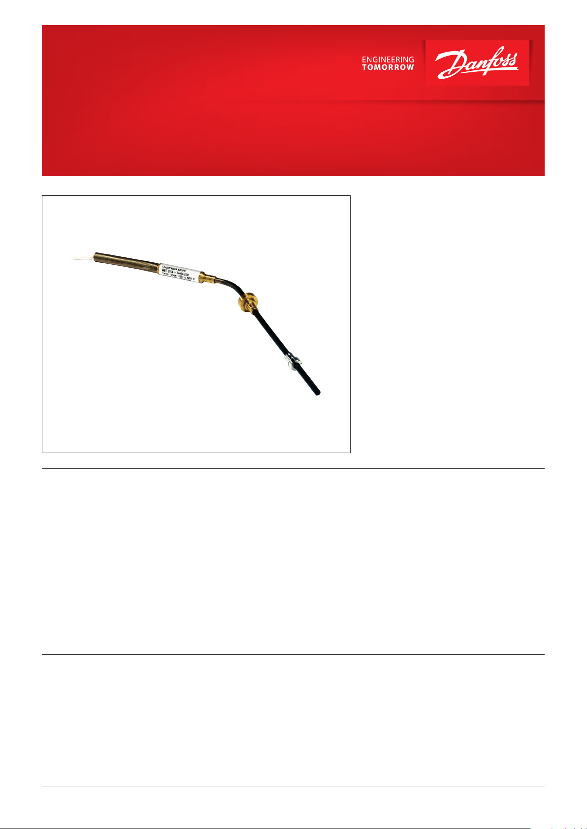
Exhaust gas temperature sensor
MBT 5114
MBT 5114 is a series of exhaust gas temperature
sensors used for performance optimization and
environmental impact control of large 4 stroke
engines.
By utilizing RTD sensing elements the MBT 5114
provides a modern and total cost attractive
alternative to the thermo couple exhaust gas
sensors.
Features
Approvals
• For measuring exhaust gas in stationary and
marine:
– diesel and gas engines
– turbines
– compressors
• Up to 600 °C media temperature (peak 700 °C)
• Fixed or adjustable insertion length
Lloyds Register of Shipping, LR
Germanischer Lloyd, GL
Det Norske Veritas, DNV
Registro Italiano Navara, RINA
• 1 or 2 Pt 1000 elements
• No need for special compensation cable.
• Less noise sensitive
• No cold junction compensation
• Resistant to moisture (works from day one)
• No polarity on the cable (easy to install)
• Linear signal
Nippon Kaiji Kyokai, NKK
American Bureau of Shipping, ABS
Korean Register of Shipping, KRS
China Classification Society, CCS
Bureau Veritas, BV
© Danfoss | DCS (im) | 2016.12
IC.PD.P30.T3.02 | 520B7543 | 1
Page 2
Data sheet | Exhaust gas temperature sensor, MBT 5114
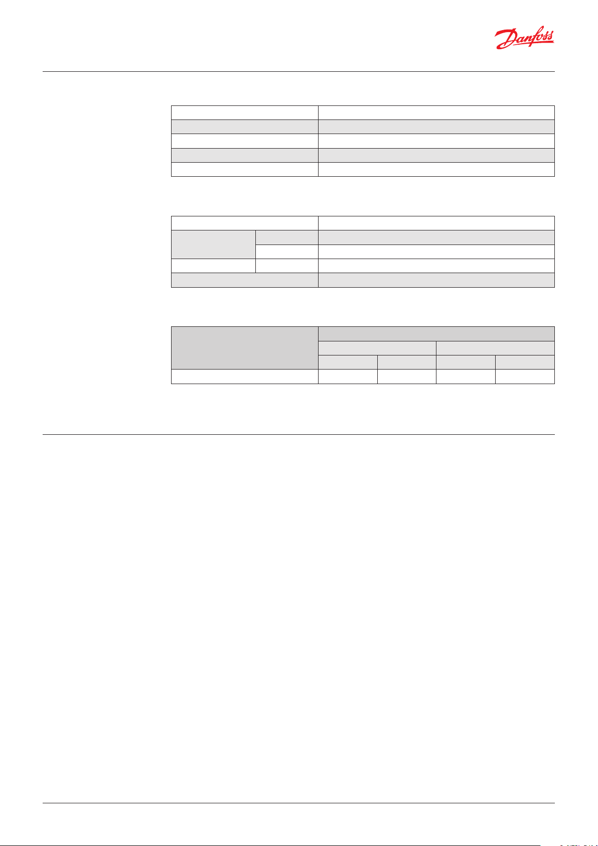
Technical data
Main specifications
Measuring range -50 – 600 °C
Short time temperature (15 min.) 650 °C
Max. peak temperature (1 min.) 700 °C
Element type Pt 1000
Tolerances EN 60751, class B
Mechanical and enviromental specifications
Ambient temperature
Vibration stability
Materials Protection tube W. no. 1.4571 (AISI 316 Ti)
Enclosure IP65 according to IEC 60529
Shock 100 g / 6 ms
Vibrations 4 g sine function 2 – 100 Hz, measured acc. to IEC 60068-2-6
Max 200 °C on the sensor housing, cable depending on type (See Page 3)
Response times
Indicative response times. Typical measured values.
Type
MBT 5114
Water 0.2 m/s Air 6 m/s
t
0.5
1 s 3.5 s 15 s 50 s
t
0.9
t
0.5
t
0.9
Mounting
The free insertion length may not exceed
25 × sensor diameter, e.g. 150 mm
with a 6 mm sensor diameter.
However, it is generally recommended that the
sensor is supported close to the tip either by the
mounting hole or by a sensor pocket.
The sensor might break in case it is mounted
without a proper support in a vibrating
application like exhaust gas monitoring.
The free insertion length is defined as the
part of the outermost sensor end that is not
supported by a pocket or a drilled hole in the
machinery.
The free length of the cable must be supported
for every ½ meter (= 100 × cable diameter).
Especially for turbo inlet/outlet applications it
is necessary to mount the sensor in a pocket to
prevent sensor damage due to high media
velocity and vibrations.
2 | 520B7543 | IC.PD.P30.T3.02
© Danfoss | DCS (im) | 2016.12
Page 3

Data sheet | Exhaust gas temperature sensor, MBT 5114
Ordering standard
Type MBT 5114
Application Length of flexible tube
1 × Pt 1000 2-wire
2 × Pt 1000 2-wire
1 × Pt 100 2-wire
2 × Pt 100 2-wire
1 × Pt 100 4-wire
Other
Protection Tube Accessories
ø4,5 mm
ø6 mm
Other
Tolerance
EN 60751 Class B
Other
Design
Straight protection tube
Bended protection tube
Insertion length L1
100 mm 0100
500 mm 0500
1000 mm 1000
xxxx mm xxxx Cable length L2
Connection type 0100 01.0 m
None
Ajustable fitting, 1 piece
Clamp
Other
Connection thread
None
¼" – 18NPT
G ½ A
Other
0
1
2
3
4
9
0 0
1 1
9
Sensor Cable Accessories
0
9
0
1
0
1
5
9
0
1 2
4 3
9 9
0500 05.0 m
1000 10.0 m
xxxx xx,x m
0
1
0000 None
0030 0.3 m
0100 1.0 m
1000 10 m
xxx0 Other
None
Flexible tube
2
9
0
9
0
1
3
9
Spring
Other
Ajustable fitting for cable
None
Other
Connection (plug)
None
Jäger 4 pins, straight
ITT Cannon 4 pins
Other
Cable type
None
PFA cable, screen, 260 °C
FEP cable, screen, 205 °C
Polyolefine cable, screen, 150 °C
Other
Preferred versions
© Danfoss | DCS (im) | 2016.12
IC.PD.P30.T3.02 | 520B7543 | 3
Page 4

Dimensions [mm]
MBT 5114 straight version, adjustable
Spring
Shield
Ferrule w.o. Collar
MBT 5114 angle version, fixed clamp
Spring
Shield
Ferrule w.o. Collar
Net weight
MBT 5114 0.1 kg
1 m cable increases net weight with approx. 40 g
© Danfoss | DCS (im) | 2016.12 IC.PD.P30.T3.02 | 520B7543 | 4
 Loading...