

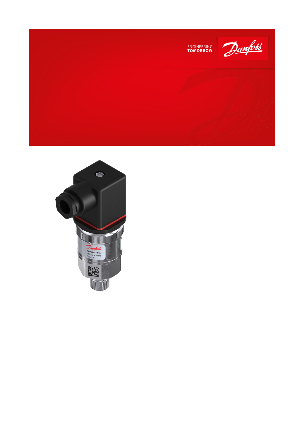
Data Sheet
Pressure transmitter
Type MBS 9300
For marine applications
Compact pressure transmitter programme, MBS
9300 gauge version is designed for use in
marine applications e.g. crankcase and
turbocharger lters monitoring as well as
applications within level measurement.
The programme covers 4 – 20 mA and
ratiometric 10-90% of supply output signals,
pressure span from 40 – 400 mbar as well as
bidirectional ranges.
Excellent vibration stability, robust
construction, and a high degree of EMC/EMI
protection equip the pressure transmitter to
meet the most stringent industrial
requirements.
Features
• Compact design
• Full scale span from 40 – 400 mbar
◦ bidirectional ranges available, e.g. -40 – 70
mbar etc.
◦ lowest zero point –150 mbar
◦ max full scale 250 mbar
• Digital temperature compensated
• Output signals 4-20 mA and Ratiometric 10-
90% of supply
• Excellent shock and vibration robustness
• Reverse polarity protection
• With build-in clipping function and self-
diagnostic features on request
• Enclosure and wetted parts of stainless steel
(AISI 316L)
• EU RO Mutual Recognition
• Customer specic versions on request
• For use in Zone 2 explosive atmosphere
AI176386432536en-000801
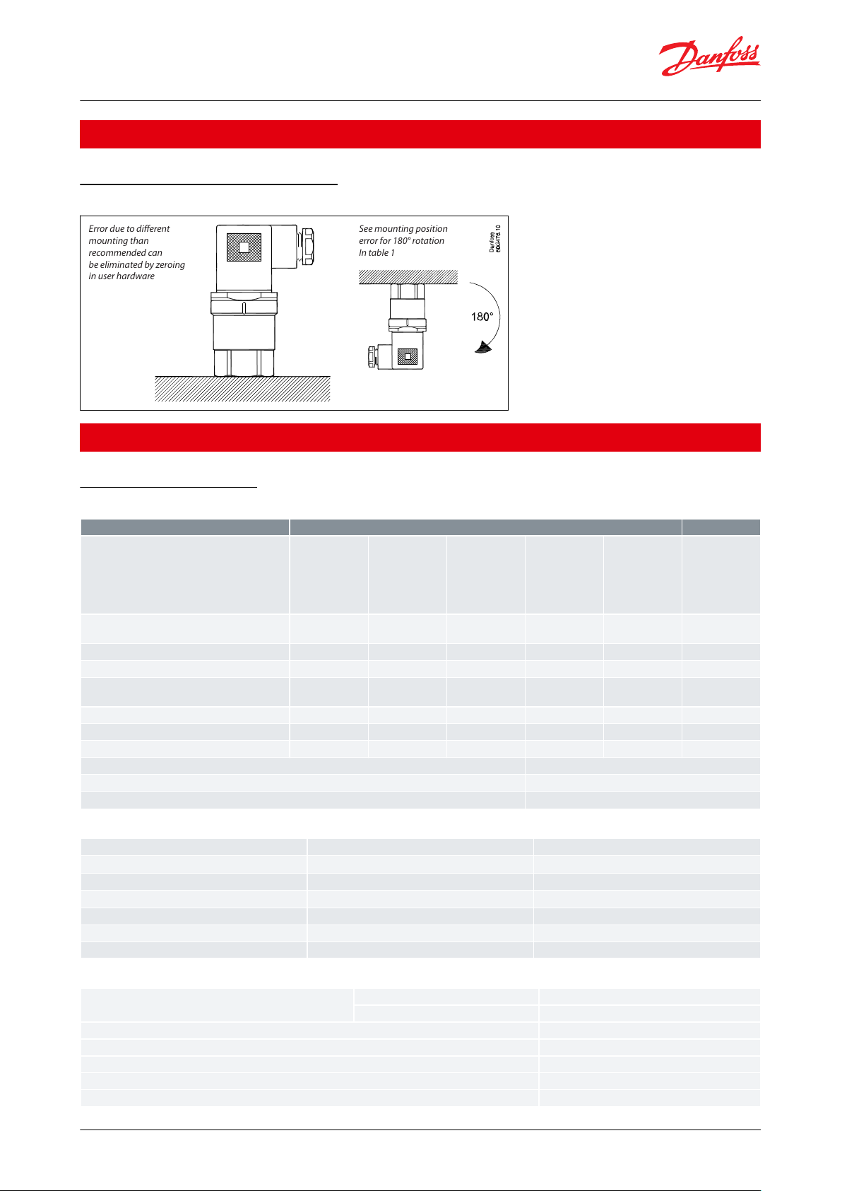
Error due to different
mounting than
recommended can
be eliminated by zeroing
in user hardware
See mounting position
error for 180° rotation
In table 1
Description
Value range
Units
Full-scale span (FSS)
Full-Scale Span (FSS) is the dierence between
the upper limit and the lower limit of the
pressure range.
(e.g. for pressure range -30 – 30 mbar, FSS = 60
mbar.)
4060100/140
150
250/400
mbar
Accuracy @ 25 °C
(incl. non-linearity, hysteresis and repeatability)
≤ ± 2
≤ ± 1.5
≤ ± 1
≤ ± 0.5
≤ ± 0.5
% FSS typ.
Non-linearity (BFSL)
≤ ± 0.2
≤ ± 0.2
≤ ± 0.2
≤ ± 0.2
≤ ± 0.2
% FSS
Hysteresis and repeatability
≤ ± 0.1
≤ ± 0.1
≤ ± 0.1
≤ ± 0.1
≤ ± 0.1
% FSS
Total error band (TEB)
within compensated temperature range
≤ ± 5
≤ ± 3
≤ ± 2
≤ ± 1.5
≤ ± 1.5
% FSS
Mounting position error for 180° rotation
≤ ± 1.25
≤ ± 0.8
≤ ± 0.5
≤ ± 0.35
≤ ± 0.2
% FSS
Overload pressure (static)
3.5
3.5
3.5
3.5
3.5
bar
Burst pressure5050505050bar
Response time
< 2 ms
Resolution
Innite
Durability P: 10 – 90% FS
10 × 106 pressure cycles
Nom. output signal (short circuit protected)
4 – 20 mA
Ratiometric 10-90% supply
Supply voltage [UB], reverse polarity protected
9 – 32 V DC
5 V DC +/- 10%
Supply voltage dependency
< ± 0.05% FSS / 10 V
-
Load [RL] (load connected to 0 V)
RL ≤ (UB - 8 V) / 0.02 A
RL ≥ 1.5 kΩ
Supply current consumption
-
≤ 6 mA
Sink / Source
-
3.3 mA
Output impedance
-
≤ 25 Ω
Media temperature range
FPM gasket
-20 °C – 100 °C
NBR gasket
-25 °C – 85 °C
Ambient temperature range
See Electrical connection
Compensated temperature range
0 °C – 80 °C
Transport / storage temperature range
-40 °C – 125 °C
EMC - Emission
EN 61000-6-3 and EN61236-1
EMC Immunity
EN 61000-6-2 and EN61236-1
Pressure transmitter, type MBS 9300
Applications
Recommended mounting position
Figure 1: Mounting position
Product specication
Technical specications
Table 1: Performance (EN 60770)
Table 2: Electrical specications
Table 3: Environmental specications
© Danfoss | Climate Solutions | 2021.03 AI176386432536en-000801 | 2
Vibration stability
Sinusoidal
15.9 mm-pp, 2 Hz – 25 Hz
IEC 60068-2-6
20 g, 25 Hz – 2 kHz
Random
7.5 g
rms
, 5 Hz – 1 kHz
IEC 60068-2-64
Shock resistance
Shock
500 g / 1 ms
IEC 60068-2-27
Free fall
1 m
IEC 60068-2-32
Enclosure (depending on electrical connection)
See Electrical connection
Zone 2 applications
(1)
EN60079-0; EN60079-15
Net weight
0.2 – 0.3 kg
Electrical connector
See Electrical connection
Pressure connection
See Electrical connection
Materials, wetted parts
EN 10088; 1.4404 (AISI 316 L)
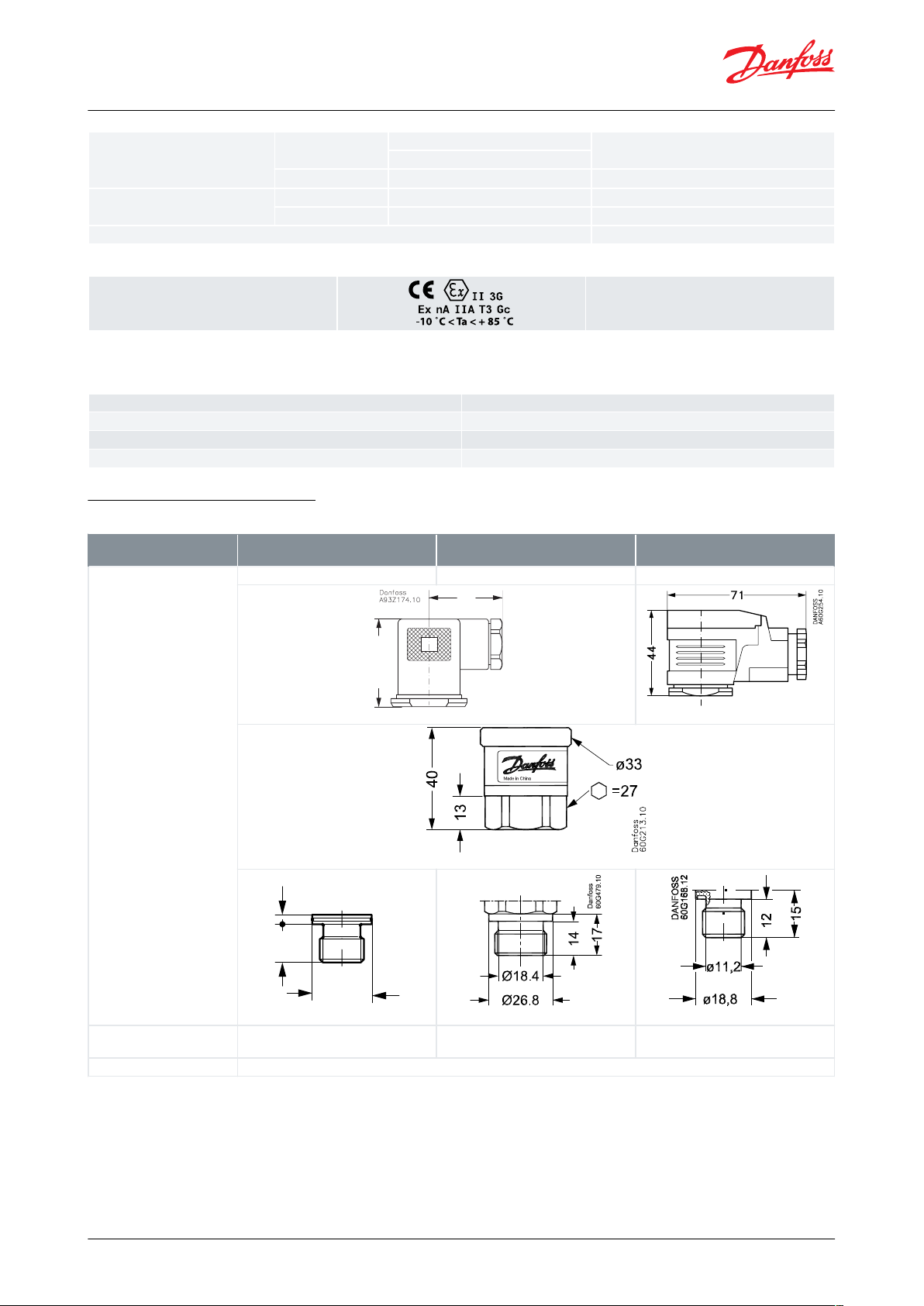
Type code:
Electrical connection
A1A6A9
EN 175301-803-A, Pg 9
EN 175301-803-A, Pg 11
EN 175301-803-A, Pg 13.5
39.5
34
3
12
Ø 18,8
Type code:
Pressure connection
DIN 3852-E, M14x1.5
DIN 3852-E, G½
DIN 3852-E, G¼
Recommended torque:
20 – 25 Nm
Pressure transmitter, type MBS 9300
Table 4: Explosive atmospheres
(1)
(1)
When used in ATEX Zone 2 areas at low temperatures the cable and plug must be protected against impact.
When used in ATEX Zone 2 areas at low temperatures the cable and plug must be protected against impact.
Table 5: Mechanical specications
Dimensions / Combinations
Table 6: Connections dimensions / combinations
© Danfoss | Climate Solutions | 2021.03 AI176386432536en-000801 | 3
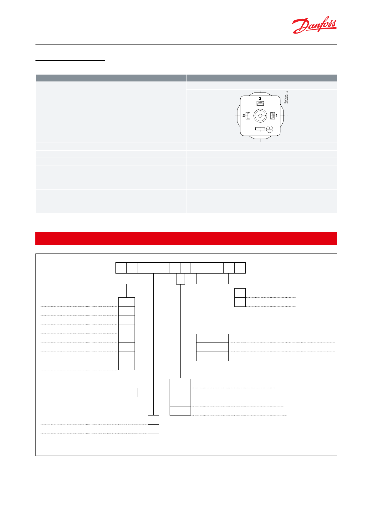
Type code
A0, A1, A6 and A9
EN 175301-803-A
Ambient temperature
-25 °C – 100 °C (ATEX zone 2 = -10 °C – 85 °C)
Enclosure
IP65
Materials
Glass lled polyamid, PA 6.6
Electrical connection
4-20 mA (2 wire)
Pin 1: + supply
Pin 2: - supply
Pin 3: Not used
Earth: Connected to transmitter enclosure
Electrical connection
Ratiometric 10-90% supply
Pin 1: + supply
Pin 2: - common
Pin 3: Output
Earth: Connected to transmitter enclosure
Type 9300 1 –
Gasket
Pressure range
1
Gasket, FPM
-20 –
20 mbar
A 1 2 Gasket, NBR
-30 –
30 mbar
A 2
-70 –
70 mbar
A 3
0 –
40 mbar
B 1 Pressure connection
0 –
60 mbar
B 2 G B 0 8
DIN 3852-E-G1/2, gasket DIN 3869-21
0 –
100 mbar
B 3 G B 0 4 DIN 3852-E-G1/4, gasket DIN 3869-14
0 –
150 mbar
B 4 F A 0 9 DIN 3852-E-M14 x1.5, gasket DIN 3869-14
0 –
250 mbar
B 5
Electrical connection
Pressure reference
A 0
No plug (EN175301-803-A)
Gauge (relative)
1 A 1 Plug Pg 9 (EN 175301-803-A)
A 6 Plug Pg 11 (EN175301-803-A)
Output signal
A 9 Plug Pg 13.5 (EN175301-803-A)
4 - 20 mA
1
Ratiometric 10 - 90% of supply
6
Non-standard build-up codes on request. However, minimum order quantities may apply.
Please contact your Danfoss officer for further information.
Pressure transmitter, type MBS 9300
Electrical connection
Table 7: Electrical connection
For proper ventilation of atmospheric reference pressure a vented cable is recommended.
Ordering
© Danfoss | Climate Solutions | 2021.03 AI176386432536en-000801 | 4
File name
Document type
Document topic
Approval authority
064G9615.06
EU Declaration
ATEX/EMCD/RoHS
Danfoss
TAA00000W0
Marine - Safety Certicate
-
DNV GL
ELE-311018XG
Marine - Safety Certicate
-
RINA
08472-D0 BV
Marine - Safety Certicate
-BV20-LD1952235-PDA
Marine - Safety Certicate
-
ABS
HTS-ETS 39049-19
Marine - Safety Certicate
-LRCPH 04967-AE006
Marine - Safety Certicate
-KRMRA000001Z
Marine - Safety Certicate
EU RO Mutual Recognition
DNV GL
E311982
Electrical - Safety Certicate
-ULE227388
Explosive - Safety Certicate
Hazardous Locations
UL
064R9402.00
Manufacturers Declaration
PED
Danfoss
064R9401.00
Manufacturers Declaration
China RoHS
Danfoss
SMS.W.II-2179-B.0
Marine - Manufacturing Permission
-
BV
B-BK-60210-1170_19
Food and Health - Performance Certi-
cate
-
PZH
Pressure transmitter, type MBS 9300
Certicates, declarations, and approvals
The list contains all certicates, declarations, and approvals for this product type. Individual code number may have
some or all of these approvals, and certain local approvals may not appear on the list.
Some approvals may change over time. You can check the most current status at danfoss.com or contact your local
Danfoss representative if you have any questions.
Table 8: Certicates and declarations
© Danfoss | Climate Solutions | 2021.03 AI176386432536en-000801 | 5
Online support
Danfoss oers a wide range of support along with our products, including digital product information, software,
mobile apps, and expert guidance. See the possibilities below.
The Danfoss Product Store
The Danfoss Product Store is your one-stop shop for everything product related—no matter where
you are in the world or what area of the cooling industry you work in. Get quick access to essential
information like product specs, code numbers, technical documentation, certications, accessories,
and more.
Start browsing at store.danfoss.com.
Find technical documentation
Find the technical documentation you need to get your project up and running. Get direct access to
our ocial collection of data sheets, certicates and declarations, manuals and guides, 3D models
and drawings, case stories, brochures, and much more.
Start searching now at www.danfoss.com/en/service-and-support/documentation.
Danfoss Learning
Danfoss Learning is a free online learning platform. It features courses and materials specically
designed to help engineers, installers, service technicians, and wholesalers better understand the
products, applications, industry topics, and trends that will help you do your job better.
Create your Danfoss Learning account for free at www.danfoss.com/en/service-and-support/learning.
Get local information and support
Local Danfoss websites are the main sources for help and information about our company and
products. Find product availability, get the latest regional news, or connect with a nearby expert—all
in your own language.
Find your local Danfoss website here: www.danfoss.com/en/choose-region.
Spare Parts
Get access to the Danfoss spare parts and service kit catalog right from your smartphone. The app
contains a wide range of components for air conditioning and refrigeration applications, such as
valves, strainers, pressure switches, and sensors.
Download the Spare Parts app for free at www.danfoss.com/en/service-and-support/downloads.
Danfoss can accept no responsibility for possible errors in catalogues, brochures and other printed material. Danfoss reserves the right to alter its
products without notice. This also applies to products already on order provided that such alterations can be made without subsequential
changes being necessary in specications already agreed. All trademarks in this material are property of the respective companies. Danfoss and
the Danfoss logotype are trademarks of Danfoss A/S. All rights reserved.
© Danfoss | Climate Solutions | 2021.03 AI176386432536en-000801 | 6
 Loading...