

Page 1
Data Sheet
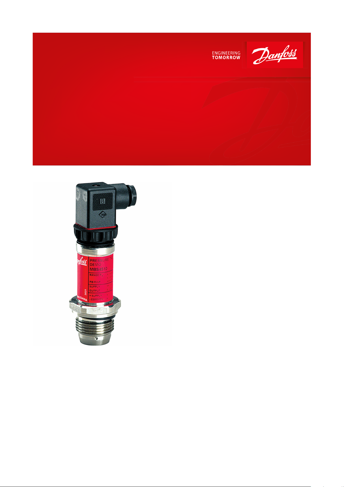
Pressure transmitter
Type MBS 4510
For industrial applications
The high accuracy ush diaphragm pressure
transmitter MBS 4510 is designed for use in
non-uniform, high viscous or crystallizing
media within industrial applications, and oers
a reliable pressure measurement, even under
harsh environmental conditions.
The exible pressure transmitter programme
covers a 4 – 20 mA output signal, absolute or
gauge (relative) versions, measuring ranges
from 0 – 0.25 to 0 – 25 bar zero and span
adjustment. A rotatable plug connection and a
G1A conic pressure connection with ush
mounted diaphragm.
Excellent vibration stability, robust
construction, and a high degree of EMC/EMI
protection equip the pressure transmitter to
meet the most stringent industrial
requirements.
Features
• Designed for use in severe industrial
environments
• Enslosure and wetted parts of acid-resistant
stainless steel (AISI 316L)
• Pressure ranges in relative (gauge) or
absolute up to 25 bar
• Output signal: 4 – 20 mA
• Temperature compensated and laser
calibrated
• Accuracy 0.5% FS
• Zero and span adjustment
• USDA-H1 approved oil lling
• For use in Zone 2 explosive atmosphere
AI235786440659en-000701
Page 2
Accuracy (incl. non-linearity, hysteresis and repeatability)
≤ ± 0.2% FS (typ.)
≤ ± 0.5% FS (max.)
Non-linearity BFSL (conformity)
≤ ± 0.2% FS
Hysteresis and repeatability
≤ ± 0.1% FS
Thermal zero point shift
Measuring range:
0 – 250 mbar
≤ ± 0.4% FS / 10K
0 – 400 mbar
≤ ± 0.3% FS / 10K
≥ 0 – 600 mbar
≤ ± 0.2% FS / 10K
Thermal sensitivity (span) shift
Measuring range:
0 – 250 mbar
≤ ± 0.4% FS / 10K
0 – 400 mbar
≤ ± 0.35% FS / 10K
≥ 0 – 600 mbar
≤ ± 0.2% FS / 10K
Response time
< 4 ms
Durability, P: 10 – 90% FS
> 10 × 106 cycles
Zero point adjustment
Measuring range:
0 – 0.25 to 0 – 10 bar
-5 – 20% FS
0 – 16 to 0 – 25 bar
-5 – 10% FS
Span adjustment
Measuring range:
0 – 0.25 to 0 – 25 bar
-5 – 5% FS
Pressure range [bar]
Max. Overload pressure [bar]
Burst pressure [bar]
-0.25 – 0.50
2500.00 – 0.25250
0.00 – 0.40250
0.00 – 0.60250
0.00 – 1.00250
0.00 – 1.60850
0.00 – 2.50850
0.00 – 4.00850
0.00 – 6.002050
0.00 – 10.00
20
50
0.00 – 16.00
100
100
0.00 – 25.00
100
100
Nom. output signal (short-circuit protected)
4 – 20 mA
Supply voltage [UB], polarity protected
10 – 30 V DC
Supply voltage dependency
≤ ± 0.1% FS / 10 V
Current limitation (linear output signal up to 1.5 × rated range)
28 mA (typ.)
Load [RL] (load connected to 0 V)
RL ≤ (UB - 10 V) / 0.02 A [Ω]
Sensor temperature range
Normal
-40 – 85 °C
ATEX Zone 2
-10 – 85 °C
Media temperature range
115 - (0.35 × ambient temperature)
Ambient temperature range
-10 – 85 °C
Compensated temperature range
0 – 80 °C
Transport / Storage temperature range
-25 – 85 °C
EMC – Emission
EN 61000-6-3
EMC – Immunity
EN 61000-6-2
Insulation resistance
> 100 MΩ at 100 V
Mains frequency test
Based on SEN 361503
Vibration stability
Sinusoidal
15.9 mm-pp, 5 Hz – 25 Hz
IEC 60068-2-6
20 g, 25 Hz – 2 kHz
Random
7.5 g
rms
, 5 Hz – 1 kHz
IEC 60068-2-64
Pressure transmitter, type MBS 4510
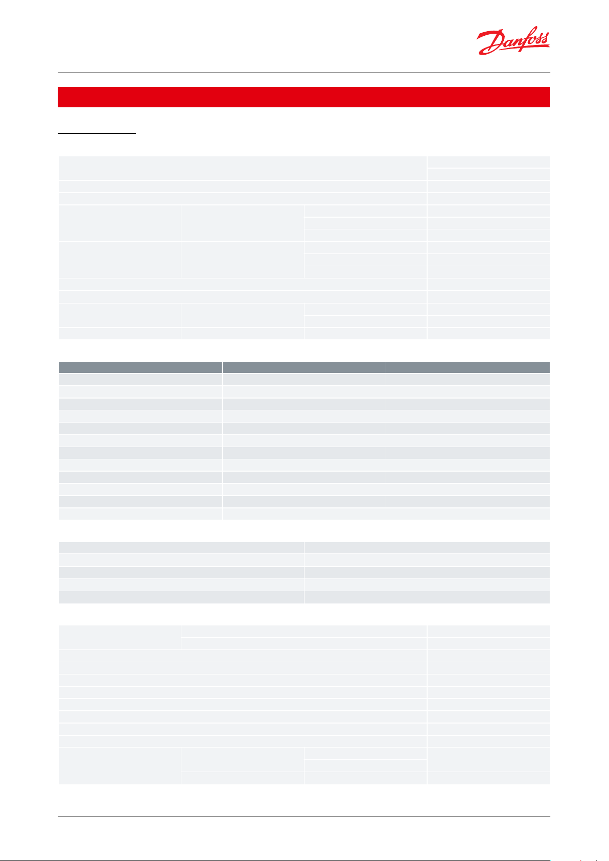
Product specication
Technical data
Table 1: Performance (EN 60770)
Table 2: Available measuring ranges
Table 3: Electrical specications
Table 4: Environmental conditions
© Danfoss | Climate Solutions | 2021.02 AI235786440659en-000701 | 2
Page 3
Shock resistance
Shock
500 g / 1 ms
IEC 60068-2-27
Free fall
1 m
IEC 60068-2-32
Enclosure (depending on electrical connection)
IP65
Zone 2 applications
(1)
EN60079-0; EN60079-15;
Materials
Wetted parts
EN 10088-1; 1.4404 (AISI 316 L)
Enclosure
EN 10088-1; 1.4404 (AISI 316 L)
Electrical connections
Glass lled polyamid PA 6.6
Gasket (above thread)
DIN 3869-33-NBR
Net weight (depending on pressure connection and electrical connection)
0.4 kg
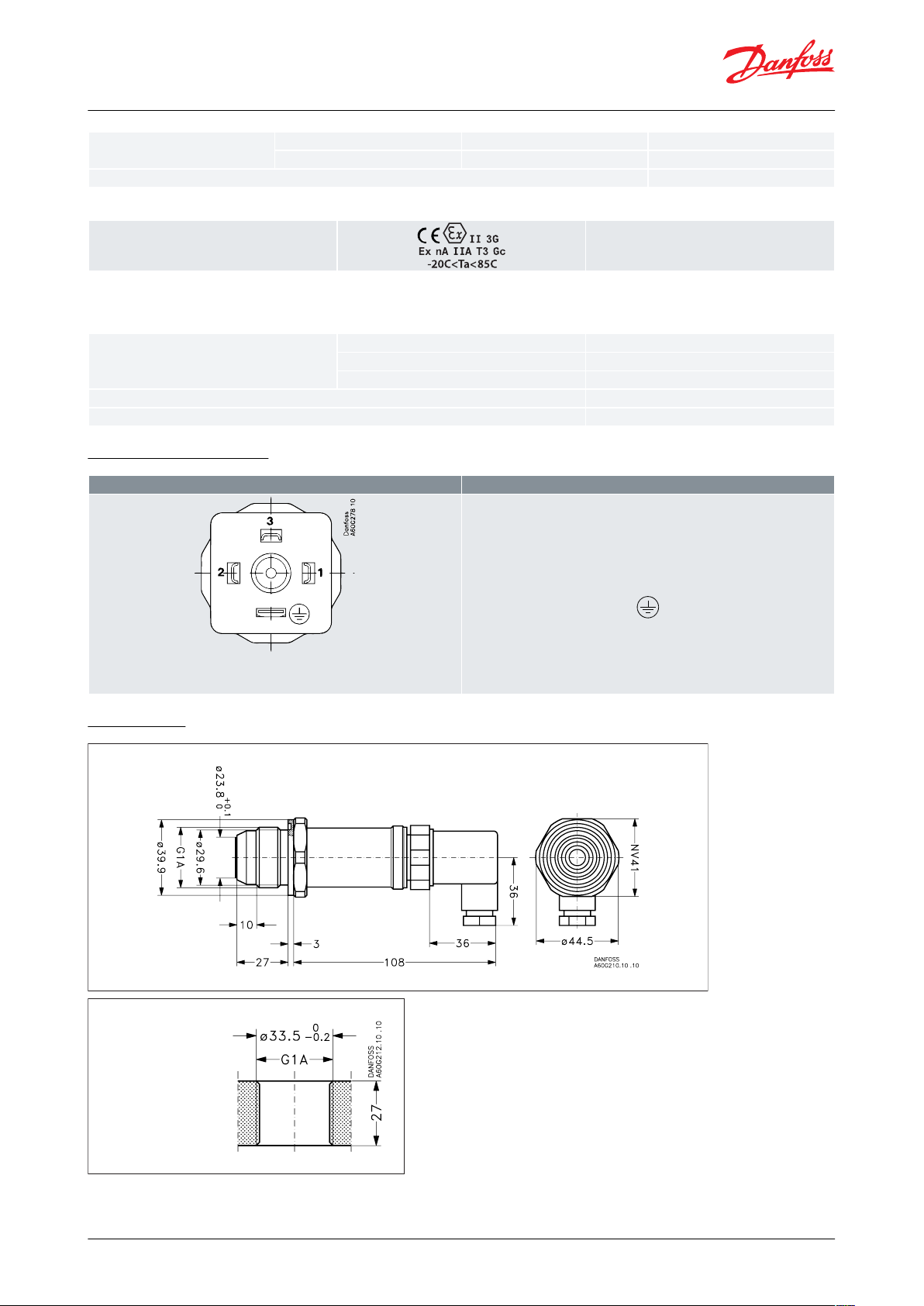
Electrical connection
4 – 20 mA output (2 wire)
EN 175301-803-A,
Pg 9
Pin 1: + supply
Pin 2: ÷ supply
Pin 3: Not used
Earth: Connected to MBS enclosure
Threaded hole
(Sealing above thread)
Pressure transmitter, type MBS 4510
Table 5: Explosive atmospheres
(1)
(1)
When used in ATex Zone 2 areas at temperatures <-10 °C the cable and plug must be protected against impact
When used in ATex Zone 2 areas at temperatures <-10 °C the cable and plug must be protected against impact
Table 6: Mechanical characteristics
Electrical connections
Dimensions
© Danfoss | Climate Solutions | 2021.02 AI235786440659en-000701 | 3
Page 4
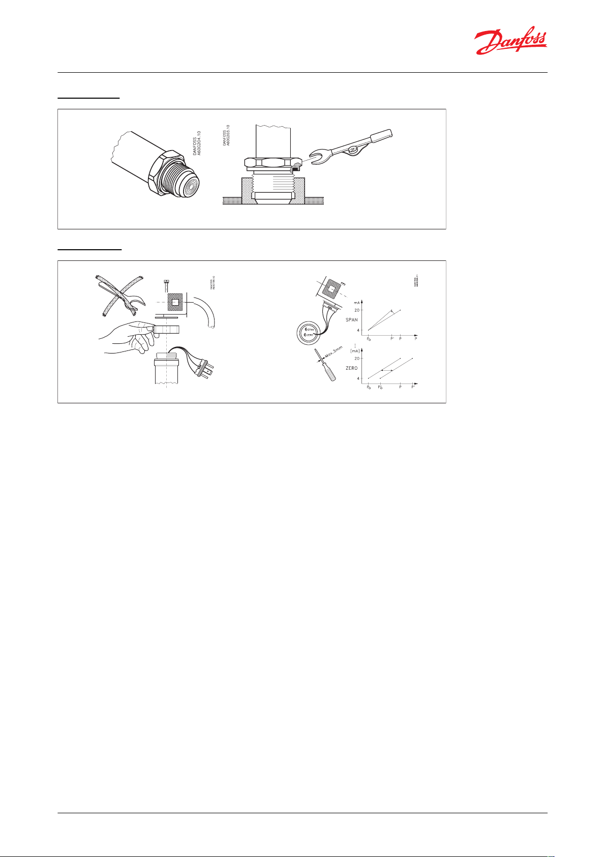
Tightening torque 60 Nm. Zero deviation of approx. 3 mbar can occur. (Can be adjusted)
-5 – 5% FS
-5 – 20% FS
-5 – 5% FS
-5 – 20% FS
Pressure transmitter, type MBS 4510
Installation
Adjustment
© Danfoss | Climate Solutions | 2021.02 AI235786440659en-000701 | 4
Page 5
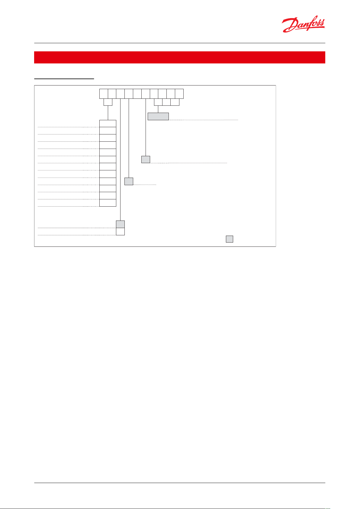
MBS 4510
1 – A1 C B 1 2
Pressure connection
Measuring range C B 1 2 G1A, ISO 228-1, Flush male
0.25 – 0.5 bar
A 4
0 – 0.25 bar
0 4
0 – 0.4 bar
0 6
0 – 0.6 bar
0 8
0 – 1.0 bar
1 0 Electrical connection
0 – 1.6 bar
1 2 A1 Plug Pg 9 (EN 175301-803-A)
0 – 2.5 bar
1 4
0 – 4.0 bar
1 6
Output signal
0 – 6.0 bar
1 8 1 4 – 20 mA
0 – 10 bar
2 0
0 – 16 bar
2 2
0 – 25 bar
2 4
Pressure reference
Gauge (relative)
1
Absolute
2
Prefered version
Pressure transmitter, type MBS 4510
Ordering
Ordering standard
© Danfoss | Climate Solutions | 2021.02 AI235786440659en-000701 | 5
Page 6
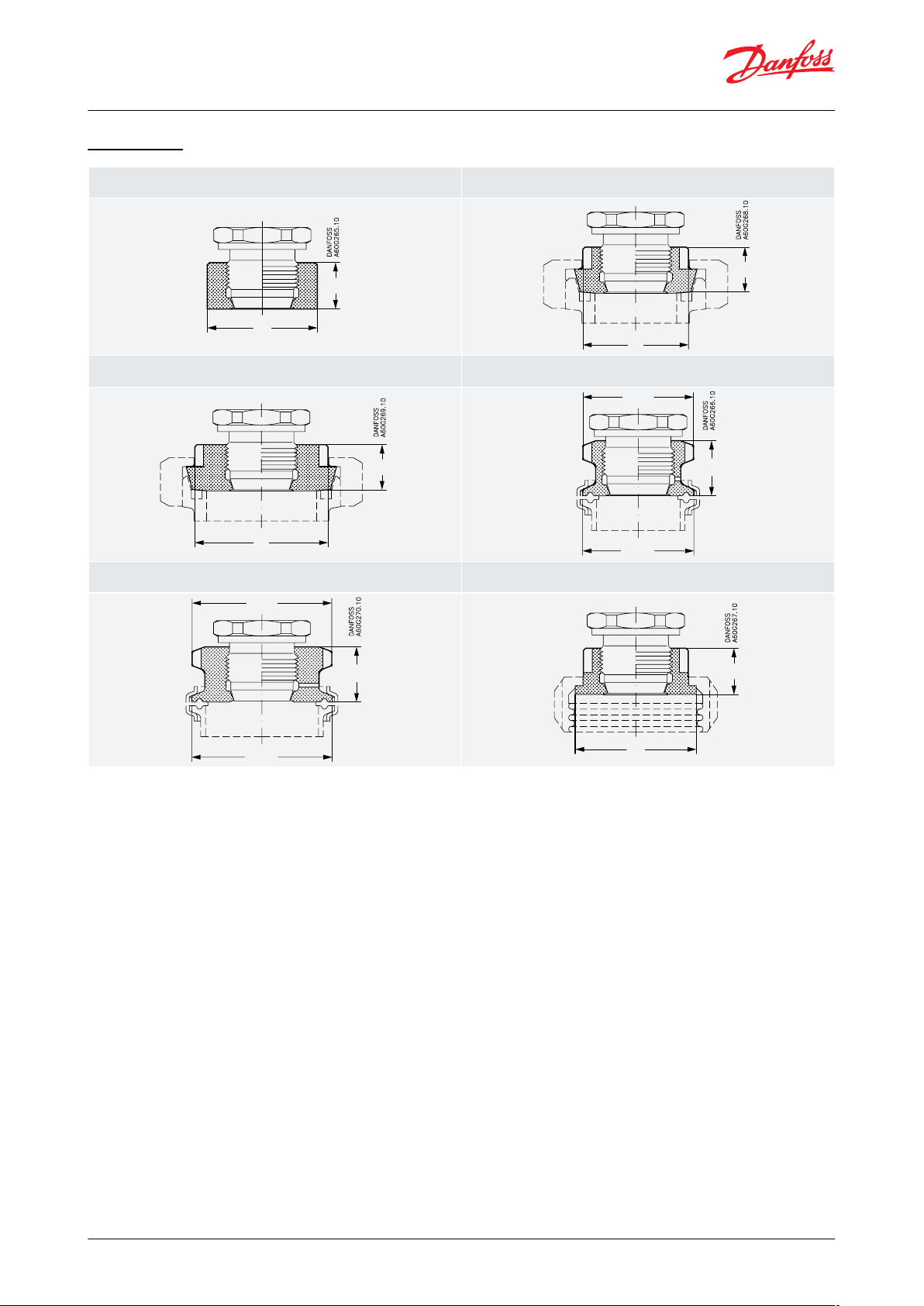
Welding nipple for conic metal/metal seal
Code no.: 060G2501
DIN 11851 (dairy connection), DN40
Code no.: 060G2505
50
21
48
21
DIN 11851 (dairy connection), DN50
Code no.: 060G2506
Clamp, ISO 2852, 1½ in.
Code no.: 060G2502
61
21
50.5
25
50.5
Clamp, ISO 2852, 2 in.
Code no.: 060G2510
SMS 1145 connection, 1½ in.
Code no.: 060G2503
64
25
64
55
21
Pressure transmitter, type MBS 4510
Accessories
© Danfoss | Climate Solutions | 2021.02 AI235786440659en-000701 | 6
Page 7

File name
Document type
Document topic
Approval authority
E227388
Explosive - Safety Certicate
Hazardous Locations
UL
E31024
Electrical - Safety Certicate
-ULE311982
Electrical - Safety Certicate
-
UL
B-BK-60210-1170_19
Food and Health - Performance Certi-
cate
-
PZH
DK.C.30.018.A 31316
Measuring - Performance Certicate
-
GOST
CN.C.30.004.A 59728-1
Measuring - Performance Certicate
-
GOST
060R3160.00
Manufacturers Declaration
China RoHS
Danfoss
064R9402.00
Manufacturers Declaration
PED
Danfoss
064G9615.06
EU Declaration
ATEX/EMCD/RoHS
Danfoss
1786330
Explosive - Safety Certicate
-
CSA
Pressure transmitter, type MBS 4510
Certicates, declarations, and approvals
The list contains all certicates, declarations, and approvals for this product type. Individual code number may have
some or all of these approvals, and certain local approvals may not appear on the list.
Some approvals may change over time. You can check the most current status at danfoss.com or contact your local
Danfoss representative if you have any questions.
Table 7: Certicates and declarations
© Danfoss | Climate Solutions | 2021.02 AI235786440659en-000701 | 7
Page 8

Online support
Danfoss oers a wide range of support along with our products, including digital product information, software,
mobile apps, and expert guidance. See the possibilities below.
The Danfoss Product Store
The Danfoss Product Store is your one-stop shop for everything product related—no matter where
you are in the world or what area of the cooling industry you work in. Get quick access to essential
information like product specs, code numbers, technical documentation, certications, accessories,
and more.
Start browsing at store.danfoss.com.
Find technical documentation
Find the technical documentation you need to get your project up and running. Get direct access to
our ocial collection of data sheets, certicates and declarations, manuals and guides, 3D models
and drawings, case stories, brochures, and much more.
Start searching now at www.danfoss.com/en/service-and-support/documentation.
Danfoss Learning
Danfoss Learning is a free online learning platform. It features courses and materials specically
designed to help engineers, installers, service technicians, and wholesalers better understand the
products, applications, industry topics, and trends that will help you do your job better.
Create your Danfoss Learning account for free at www.danfoss.com/en/service-and-support/learning.
Get local information and support
Local Danfoss websites are the main sources for help and information about our company and
products. Find product availability, get the latest regional news, or connect with a nearby expert—all
in your own language.
Find your local Danfoss website here: www.danfoss.com/en/choose-region.
Spare Parts
Get access to the Danfoss spare parts and service kit catalog right from your smartphone. The app
contains a wide range of components for air conditioning and refrigeration applications, such as
valves, strainers, pressure switches, and sensors.
Download the Spare Parts app for free at www.danfoss.com/en/service-and-support/downloads.
Danfoss can accept no responsibility for possible errors in catalogues, brochures and other printed material. Danfoss reserves the right to alter its
products without notice. This also applies to products already on order provided that such alterations can be made without subsequential
changes being necessary in specications already agreed. All trademarks in this material are property of the respective companies. Danfoss and
the Danfoss logotype are trademarks of Danfoss A/S. All rights reserved.
© Danfoss | Climate Solutions | 2021.02 AI235786440659en-000701 | 8
 Loading...