

Instructions
Pressure transmitters
MBS 4201, MBS 4251, MBS 4701 and MBS 4751
Content
Page
1 Description/application
060R9345
2 Identication
3 Specications
4 Safety instructions
5 Installation/dimensions
6 Electrical connection
6 Maintenance/adjustment
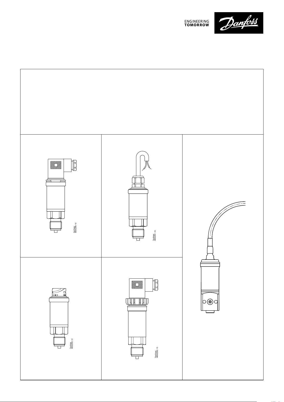
Description/Application
Application: Pressure measurement in potentially explosive areas.
Approval: Ex ia IIC T6...T4 (MBS 42xx series) and Ex ia IIC T4 (MBS 47xx series) in accordance
with ATEX directive 2014/34/EU.
Function: Pressure transmitters type MBS 4201, MBS 4251, MBS 4701 and MBS 4751 convert
the pressure measured to a 4 – 20 mA current signal.
060R9345
Danfoss
060G9056
© Danfoss | DCS (im) | 2019.07 IC.PI.P20.C9.02 | 520B8674 | 1
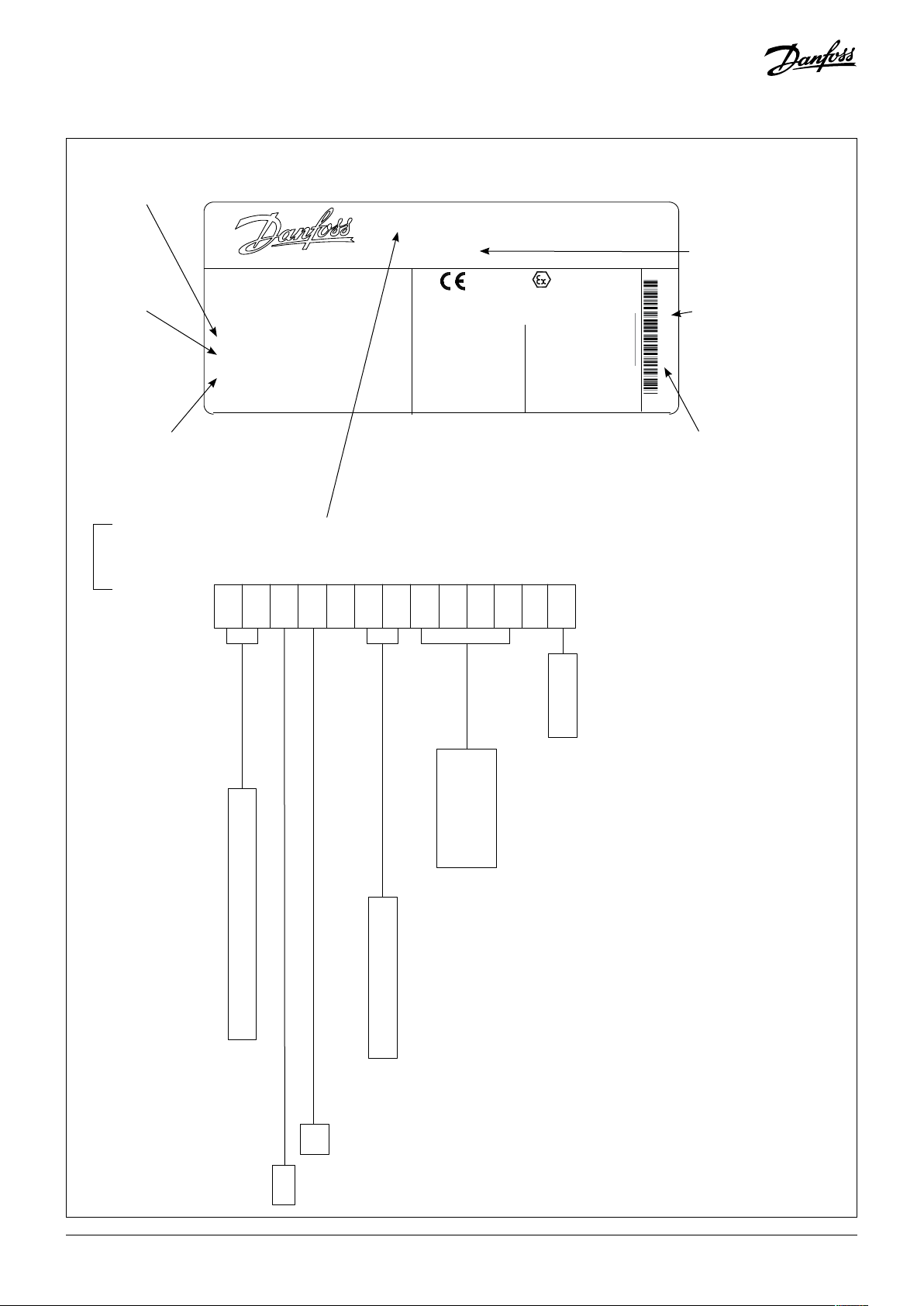
Identication
PRESSURE TRANSMITTER
Made in China
3316
Supply voltage
Output signal
Range P
e
PB/MWP
SUPPLY
OUTPUT
+SUPPLY :
-COMMON
MADE IN DENMARK
:
0...10 bar
0...1MPa
:
2 MPa/20 bar / 800 kPa
:
10...28 V DC
:
4...20 mA
PIN 1
:
PIN 2
MBS 4701-2011- A1AB08-0
060G4307
0539
DEMKO 01 ATEX 127938X
EEx ia IIC T4 GA
IECEx ULD 12.00005X
Ui : 28V
Ii : 100 mA
: 0,7 W
Pi
:
Li 8 μH
:
Ci 50 nF
II 1G
For :
Ambient
temperature
See:
user instruction
Code number
111 = WW Y
Production - week/year
(WW/Y)
02803111
Electrical connection
Type no. (Indicates transmitter specication - see key below)
Type no.
MBS 4201MBS 4251MBS 4701-
1 – –
MBS 4751-
Measuring range
0 – 1 bar ..................
0 – 1.6 bar ..................
0 – 2.5 bar ..................
0 – 4 bar ..................
0 – 6 bar ..................
0 – 10 bar ..................
0 – 16 bar ..................
0 – 25 bar ..................
0 – 40 bar ..................
0 – 60 bar ..................
0 – 100 bar ..................
0 – 160 bar ..................
0 – 250 bar ..................
0 – 400 bar ..................
0 – 600 bar ..................
10
12
14
16
18
20
22
24
26
28
30
32
34
36
38
A0 ...........
A1 ...........
A6 ...........
G9 ...........
DB ...........
DC ...........
J1 ...........
DF ...........
DH ...........
02803 = Serial no.
Gasket
0 ...........
1 ...........
2 ...........
3 ...........
4 ...........
0 N0 Gasket
1 Gasket Viton -20 °C – 125 °C
2 Gasket NBR -40 °C – 85 °C
3 O-Ring Viton -20 °C – 125 °C
4 O-Ring NBR -40 °C – 125 °C
Pressure connection
G B 0 4 .........
A B 0 8 .........
A C 0 4 .........
A C 0 8 .........
F A 0 8 .....
D F 0 2 .........
DIN 3852-E-G1/4, Gasket: DIN 3869-14-NBR
G1/2A (EN 837)
1/4-18 NPT
1/2-14 N PT
....
ISO 6149-2, M14x1.5 -6g, O-ring 11.3x2.2, NBR
M10 x 1 female with ange connection 1)
1
) Only MBS 4201 and MBS 4251
Electrical connection
No Plug EN 175301-803-A
Plug PG9 EN 175301-803-A
Plug PG11 EN 175301-803-A
Plug Bayonet A1-3.2- ISO 15170-Sn )
Cable Screened 2m Blue PVC )
Cable Screened 5m Blue PVC )
Cable Screened 7m Blue PVC )
Cable Screened 12m Black ETFE Marine approved )
Cable Screened 6m Black ETFE Marine approved )
1
) Only MBS 4201 and MBS 4251
Output signal
1 .............................
1 ........................................
2 ........................................
4 – 20 mA
Pressure reference
Gauge
Absolute
© Danfoss | DCS (im) | 2019.072 | 520B8674 | IC.PI.P20.C9.02

Specications
Output current 4 – 20 mA
Supply voltage 10 – 28 V
Safety specications
Electrical
Max. supply voltage Ui 28 V
Max. Input current Ii 100 mA
Max. Input power Pi 0.7 W
Internal capacity Ci 50 nF
Internal inductance Li 8 μH
Adjustable Type, MBS47x1-xxxx-Yxxxx (Y=A0, A1, A6, G9 are indicative for plug type)
Ambient temperature T4 -40 – 100 °C
Media temperature T4 -40 – 125 °C
Plug Type, non-adjustable, MBS42x1-xxxx-Yxxxx (Y=A0, A1, A6, G9 are indicative for plug type)
T4 -40 – 100 °C
Ambient temperature
Media temperature
T5 -40 – 75 °C
T6 -40 – 50 °C
T4 -40 – 125 °C
T5 -40 – 95 °C
T6 -40 – 50 °C
Fixed Cable Types, non-adjustable, MBS 42x1-xxxx-Yxxxx (Y = DB, DC, J1, DF, DH are indicative cable lengths, max. 12 m)
Ambient temperature (xed installations)
Ambient temperature (cables exed during
installation or operation)
Media temperature
DB, DC, J1 PVC
cable
T4 -40 – 80 °C -40 – 95 °C
T5 -40 – 75 °C -40 – 75 °C
T6 -40 – 50 °C -40 – 50 °C
T4 -5 – 70 °C -5 – 70 °C
T5 -5 – 70 °C -5 – 70 °C
T6 -5 – 50 °C -5 – 50 °C
T4 -40 – 125 °C -40 – 125 °C
T5 -40 – 95 °C -40 – 95 °C
T6 -40 – 50 °C -40 – 50 °C
DH, DF ETFE cable
Pressure specication
Measuring range bar 0 – 1
Overload (Static) bar 6 12 24 24 60 60 150 150 300 360 600 120 0 150 0 1500 1500
Burst pressure bar 100 100 100 100 100 100 150 150 400 800 1200 12 00 2000 2000 2000
0 – 1.6 0 – 2.5
0 – 4 0 – 6 0 – 10 0 – 16 0 – 25 0 – 40 0 – 60
0 – 100
0 – 160
0 – 250
0 – 400 0 – 600
© Danfoss | DCS (im) | 2019.07 IC.PI.P20.C9.02 | 520B8674 | 3

Safety Instructions
EN 175301-803-A Bayonet A1-3.2- ISO 15170-Sn
Materials of electrical connections Glass lled polyamid, PA 6.6 Glass lled polyester, PBT PVC cable or ETFE
Protection IP65 IP67 / IP69K IP67
Safety instructions
All national safety regulations must be complied with in connection with installation, start-up and operation of Danfoss pressure
transmitters type
national regulations for installation
MBS 4201, MBS 4251, MBS 4701 and MBS 4751. Furthermore, the requirements of the Declaration of Conformity and
in explosion areas apply. Disregarding such regulations involves a risk of serious personal injury or
extensive material damage.
Work in connection with the pressure transmitters mentioned must be performed only by suitably qualified persons.
Basic safety and health requirements are fulfilled through compliance with:
EN60079-0:2012+A11:2013: 2012, IEC60079-0: 6th edition, EN60079-11: 2012, IEC60079-11: 6th edition, EN60079-26: 2015, IEC60079-26:
3rd edition.
Special Ex protection instructions: In the event of damage to enclosure or diaphragm, the pressure transmitter must be replaced.
The end user must ensure the installation is made in accordance to IEC/EN60079-25 and IEC/EN60079-14.
WARNING –Potential Electrostatic Charging Hazard. The transmitter must only be installed in surroundings with low wind speed, and
where rubbing on the plug is unlikely. Cleaning with a damp cloth is recommended. To avoid build -up of electrostatic discharge it
must be ensured the pressure connection of the pressure transmitter is having a reliable connection to earth with an impedance no
exceeding 1 Gohm.
The MBS transmitters do not provide isolation meeting the dielectric strength requirements of IEC/EN60079-11.
MBS transmitters contain 10 nF capacitance from any input terminal to earth.
Special conditions for safe use in accordance to the ATEX/IECEx certificate:
For installations in which both the Ci and Li of the connected apparatus exceeds 1% of Co and Lo parameters (excluding the cable),
then 50% of Co and Lo parameters are applicable and shall not be exceeded.
Special precautions are necessary to reduce the risk due to electro-static discharge. The transmitter must only be installed in sur-
roundings with low wind speed, and where rubbing the plug is unlikely. Cleaning with a damp cloth is recommended.
The installation shall ensure that the resistance to earth of metallic parts of the equipment enclosure is less than 1 GOhm.
The equipment does not provide 500 V isolation to earth as required by IEC/EN60079-11: clause 6.3.13.
Installations of the pressure connection across boundary walls requiring Category 1G equipment and a less hazardous area must
be gas tight as required by IEC/EN60079-26. Gaskets and seals used at the pressure connection must be suitable for use with the
process medium.
Special instruction when adjusting MBS 47xx series:
If possible only adjust the MBS in non-hazardous area or take precaution to avoid electrostatic discharge and ensure the earthen of
the transmitter housing is maintained. The transmitter must always be supplied from an intrinsic safety barrier.
Demands on the medium:
Parts in contact with the medium are made of stainless steel, EN 1088-1 1.4404 (AISI 316L). The user is responsible for a careful analysis
of all process parameters when materials have to be specified and for ensuring the process medium is neutral to stainless steel as
some media can be corrosive. The end user must ensure that the process connection is gas tight (as required by IEC/EN60079-26)
which may require the use of a suitable gasket/seal in combination with the process connection to obtain a gas-tight connection.
Gaskets and seals used at the pressure connection, including those supplied with the transmitters, must be determined as being
suitable for use with the process medium and process pressure/temperature before use and alternative gasket material chosen if
necessary. The end user must ensure the transmitter pressure connection is tightened with the correct torque as required for the
specific thread type.
In case of problems please contact: Danfoss A/S
DK-6430 Nordborg
Denmark
You find the EC-Type Examination Certificate at: www.ia.danfoss.com/ATEXcertificate
© Danfoss | DCS (im) | 2019.074 | 520B8674 | IC.PI.P20.C9.02

Installation/dimensions
87
MBS 4201
MBS 4251
DIN3852-E-G¼
Gasket: DIN 3869-14-NBR
G½ A (EN 837) ¼ - 18 NPT ½ - 14 NPT
MBS 4701
MBS 4751
ISO 6149-2
M14 x 1.5-6g
incl. O-ring
NBR
MBS 4201
MBS 4251
41
35
15
20
30.7
Flange connection
Danfoss
060G9055
ø33.5
2 x ø5.4
M10 x 1
Dimensioned sketch Example
© Danfoss | DCS (im) | 2019.07 IC.PI.P20.C9.02 | 520B8674 | 5

Electrical connection
Danfoss
060G9056
EN 175301-803-A
+ -
Pin 1 Pin 2
IS O 15170
+ -
Pin 1 Pin 2
PVC cable (Blue)
+ -
Black 1 Black 2
ETFE Cable (black)
+ -
Black Blue
MBS 4201
MBS4251
MBS 4701
MBS4751
Cables must be specified for a minimum test voltage of 500 VAC between conductor/earth, conductor/screen and screen/earth.
In addition, the total capacity and inductivity of the installation (transmitter + cable) must be taken into consideration.
In Zone 0 an intrinsically safe type Ex ia circuit must be used and national regulations for Zone 0 must be complied with. The pressure
transmitter must only be used in Zone 0 at atmospheric pressure between 0.8 and 1.1 bar and at ambient temperatures
between -20 and 50 °C.
Maintenance/Adjustment
Zero adjustment
0 – 1 to 0 – 10 bar -5 – 20% FS
0 – 16 to 0 – 40 bar -5 – 10% FS
0 – 60 to 0 – 600 bar -2.5 – 2.5 FS
Span adjustment -5 – 5% FS
See table
Danfoss pressure transmitters type MBS 4201, MBS 4251, MBS 4701 and MBS 4751 are maintenance free.
Zero point and span (measurement area) adjustment is possible on MBS 4701 and MBS 4751.
Adjustment procedure (see drawing):
Loosen screw at top of the EN 175301-803-A plug. Remove plug.
Unscrew the black milled nut from the pressure transmitter and remove the EN 175301-803-A Plug insert from the transmitter.
Install the plug on the DIN 43650 insert and connect the current measuring instrument.
Adjust the zero point on the potentiometer below the hole marked ZERO.
Adjust the span (measuring range) on the potentiometer below the hole marked SPAN (precise pressure reference must be used).
Do not remove the silicone during adjustment. Be sure that the potentiometer is covered with silicone after adjustment
© Danfoss | DCS (im) | 2019.076 | 520B8674 | IC.PI.P20.C9.02
 Loading...