

Page 1
Data Sheet
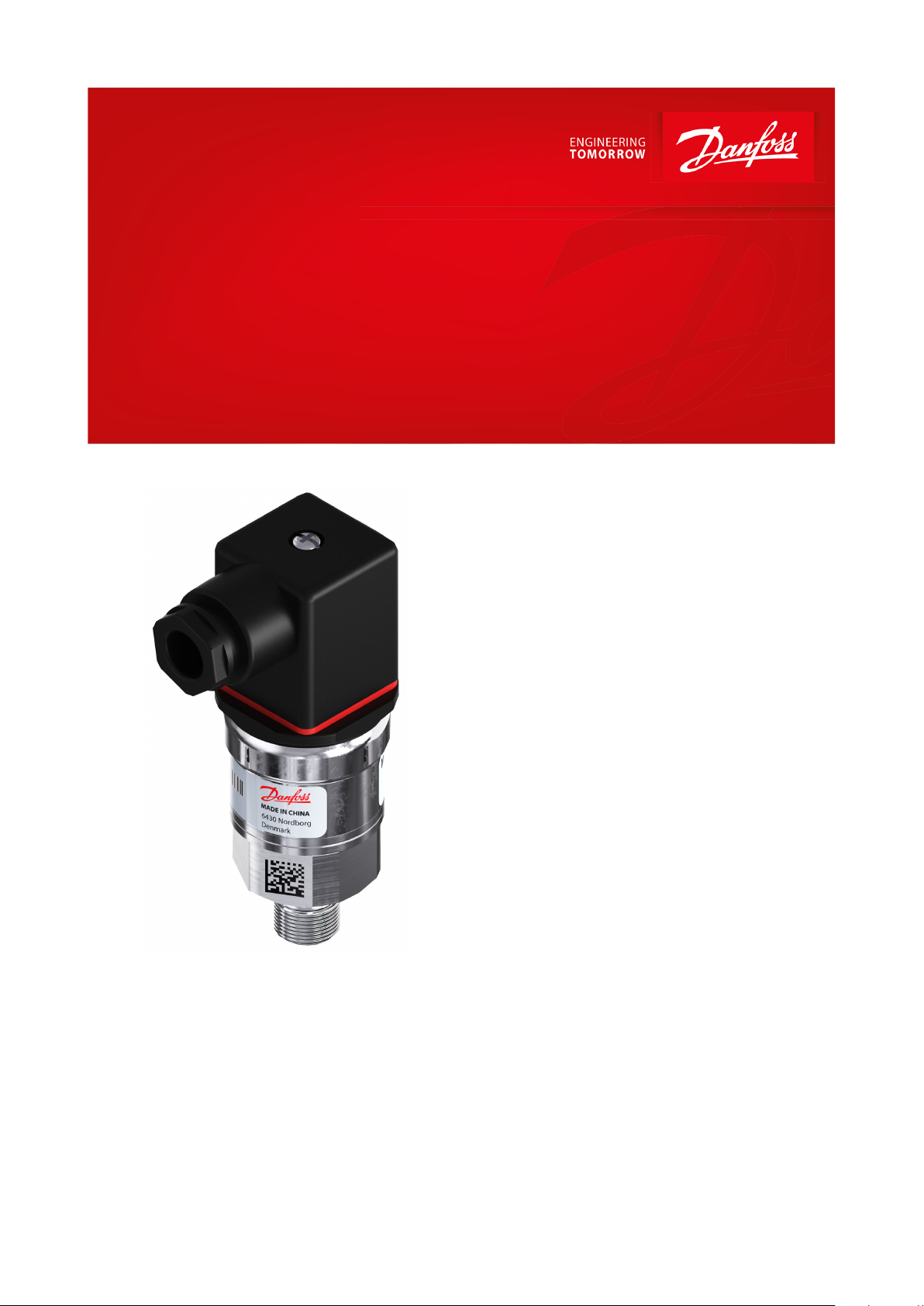
Pressure transmitter
Type MBS 4000
Oers high accuracy
The high accuracy pressure transmitter MBS
4000 is designed for use in almost all industrial
applications, and oers a reliable pressure
measurement, even under harsh environmental
conditions.
The exible pressure transmitter programme
covers a 4 – 20 mA output signal, absolute or
gauge (relative) versions, measuring ranges
from 0 – 1.6 to 0 – 400 bar. A wide range of
pressure connections.
Excellent vibration stability, robust
construction, and a high degree of EMC / EMI
protection equip the pressure transmitter to
meet the most stringent industrial
requirements.
Features
• Designed for use in severe industrial
environments
• Enslosure and wetted parts of acid-resistant
stainless steel (AISI 316L)
• Pressure ranges in relative (gauge) or
absolute from 0 up to 400 bar
• Output signal: 4 – 20 mA
• A wide range of pressure connections
• Fully digitally compensated
• Accuracy 0.5% FS max.
• UL approved
AI377939046896en-000201
Page 2
Description
Values
Accuracy (incl. non-linearity, hysteresis and repeatability)
≤ ± 0.2% FS (typ.)
≤ ± 0.5% FS (max.)
Non-linearity BFSL (conformity)
≤ ± 0.2% FS
Hysteresis and repeatability
≤ ± 0.1% FS
Thermal zero point shift
≤ ± 0.1% FS/10 K (typ.)
≤ ± 0.2% FS/10 K (max.)
Thermal sensitivity (span) shift
≤ ± 0.1% FS/10 K (typ.)
≤ ± 0.2% FS/10 K (max.)
Response time
< 4 ms
Overload pressure
6 × FS (max. 1500 bar)
Burst pressure
6 × FS (max. 2000 bar)
Power-up time
< 50 ms
Durability, P: 10 – 90% FS
> 10 ×106 cycles
Description
Values
Nom. output signal (short-circuit protected)
4 – 20 mA
Supply voltage [UB], polarity protected
9 – 32 V DC
Supply voltage dependency
< 0.1% FS / 10 V
Output limitation
22.4 mA
Load [RL] (load connected to 0 V)
RL≤
(UB − 9V)
0.02A
[Ω]
Description
Values
Sensor operating temperature
Normal
-40 – 85 °C
Media temperature range
-40 – 85 °C
Ambient temperature range
-40 – 85 °C
Compensated temperature range
0 – 80 °C
Transport / Storage temperature range
-50 – 85 °C
EMC – Emission
EN 61000-6-3
EMC – Immunity
EN 61000-6-2
Insulation resistance
> 100 MΩ at 500 V DC
Mains frequency test
Based on SEN 361503
Vibration stability
Sinusoidal
15.9 mm-pp, 5 Hz – 25 Hz
IEC 60068-2-6
20 g, 25 Hz – 2 kHz
Random
7.5g
rms
, 5 Hz – 1 kHz
IEC 60068-2-64
Shock resistance
Shock
500 g/1 ms
IEC 60068-2-27
Free fall
1 m
IEC 60068-2-32
Enclosure (IP protection fullled together with mating connector)
IP65
Description
Values
Materials
Wetted parts
EN 10088-1; 1.4404 (AISI 316 L)
Enclosure
EN 10088-1; 1.4404 (AISI 316 L)
Electrical connections
Glass lled polyamid, PA 6.6
Net weight (depending on pressure connection)
0.2 – 0.3 kg
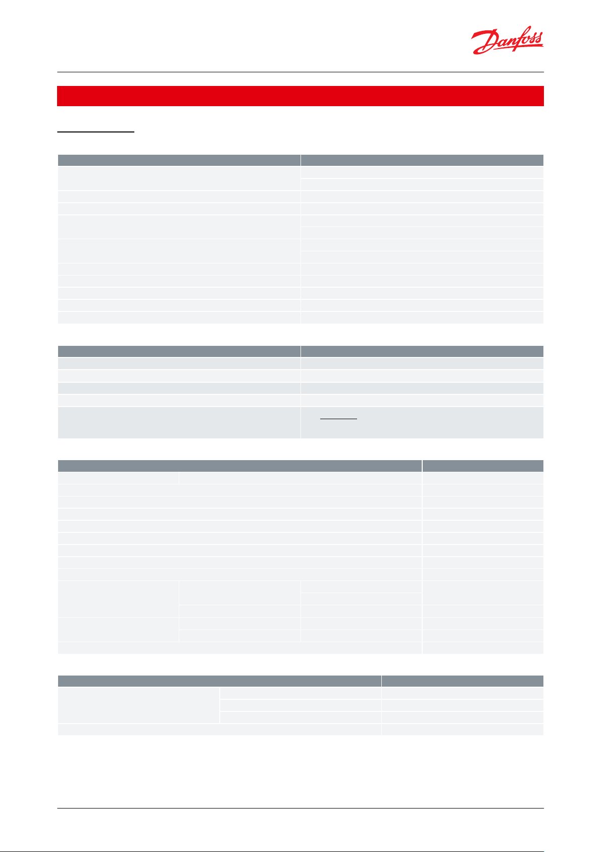
Pressure transmitter, Type MBS 4000
Product specication
Technical data
Table 1: Performance (EN 60770)
Table 2: Electrical specications
Table 3: Enviromental conditions
Table 4: Mechanical characteristics
© Danfoss | Climate Solutions | 2021.06 AI377939046896en-000201 | 2
Page 3

Description
Values
Zone 2 applications
(1)
EN60079-0; EN60079-7
Type code
A1
EN 175301-803-A, Pg 9
Electrical connection, 4 – 20 mA output (2 wire)
Pin 1: + supply
Pin 2: ÷ supply
Pin 3: not used
Earth: Connected to MBS enclosure
Pressure transmitter, Type MBS 4000
Table 5: Explosive atmospheres
(1)
(1)
When used in ATEX Zone 2 areas at low temperatures the cable and plug must be protected against impact.
When used in ATEX Zone 2 areas at low temperatures the cable and plug must be protected against impact.
Electrical connection
Figure 1: Electrical connection
Table 6: Electrical connection
© Danfoss | Climate Solutions | 2021.06 AI377939046896en-000201 | 3
Page 4

G ¼ A
(EN 837) (EN 837)
G ½ A
(EN 837)
¼ – 18 NPT ½ – 14 NPT
G ¼
(DIN 3852-E)
Type code AB04 AB06 AB08 AC04 AC08 GB04
Recommended
torque1)
30 – 35 Nm 30 – 35Nm 30 – 35 Nm
2 – 3 turns after
f inger tightened
2 – 3 turns after
f inger tightened
30 – 35 Nm
Type code A1
3
39.5
Pressure transmitter, Type MBS 4000
Dimensions and weights
Figure 2: Dimensions/Combinations
1
) Depends on dierent parameters such as gasket material, mating material, thread lubrication and pressure level
© Danfoss | Climate Solutions | 2021.06 AI377939046896en-000201 | 4
Page 5

MBS 40
1 – A1 –
Gasket / O-ring material
0 No gasket
2 Gasket, NBR -40 °C – 85 °C
4 O-ring, NBR -40 °C – 85 °C
Pressure connection
G ¼ A (EN 837)
Measuring range
G ½ A (EN 837)
0 – 1.6 bar
1 2
A C 0 4
A B 0 8
A B 0 6
A B 0 4
A C 0 8
G B 0 4
¼ – 18 NPT
0 – 2.5 bar
1 4
½ – 14 NPT
0 – 4.0 bar
1 6
G ¼ (DIN 3852-E)
0 – 6.0 bar
1 8
0 – 10 bar
2 0
0 – 16 bar
2 2
Electrical connection
0 – 25 bar
2 4
0 – 40 bar
2 6
A1 Plug Pg9 (EN175301-803-A)
0 – 60 bar
2 8
0 – 100 bar
3 0
0 – 160 bar
3 2
0 – 250 bar
3 4
Output signal
0 – 400 bar
3 6
4 – 20 mA
Pressure reference
Gauge (relative)
1
Absolute
2
Preferred version
1
Standard 0 0
With pulse-snubber 5 0
Pressure transmitter, Type MBS 4000
Ordering
Figure 3: Ordering standard
NOTE:
Non-standard build-up combinations may be selected. However, minimum order quantities may apply.
Please contact your local Danfoss oce for further information, or request on other versions.
© Danfoss | Climate Solutions | 2021.06 AI377939046896en-000201 | 5
Page 6

Online support
Danfoss oers a wide range of support along with our products, including digital product information, software,
mobile apps, and expert guidance. See the possibilities below.
The Danfoss Product Store
The Danfoss Product Store is your one-stop shop for everything product related—no matter where
you are in the world or what area of the cooling industry you work in. Get quick access to essential
information like product specs, code numbers, technical documentation, certications, accessories,
and more.
Start browsing at store.danfoss.com.
Find technical documentation
Find the technical documentation you need to get your project up and running. Get direct access to
our ocial collection of data sheets, certicates and declarations, manuals and guides, 3D models
and drawings, case stories, brochures, and much more.
Start searching now at www.danfoss.com/en/service-and-support/documentation.
Danfoss Learning
Danfoss Learning is a free online learning platform. It features courses and materials specically
designed to help engineers, installers, service technicians, and wholesalers better understand the
products, applications, industry topics, and trends that will help you do your job better.
Create your Danfoss Learning account for free at www.danfoss.com/en/service-and-support/learning.
Get local information and support
Local Danfoss websites are the main sources for help and information about our company and
products. Find product availability, get the latest regional news, or connect with a nearby expert—all
in your own language.
Find your local Danfoss website here: www.danfoss.com/en/choose-region.
Spare Parts
Get access to the Danfoss spare parts and service kit catalog right from your smartphone. The app
contains a wide range of components for air conditioning and refrigeration applications, such as
valves, strainers, pressure switches, and sensors.
Download the Spare Parts app for free at www.danfoss.com/en/service-and-support/downloads.
Coolselector®2 - nd the best components for you HVAC/R system
Coolselector®2 makes it easy for engineers, consultants, and designers to nd and order the best
components for refrigeration and air conditioning systems. Run calculations based on your operating
conditions and then choose the best setup for your system design.
Download Coolselector®2 for free at coolselector.danfoss.com.
Any information, including, but not limited to information on selection of product, its application or use, product design, weight, dimensions, capacity or any other
technical data in product manuals, catalogues descriptions, advertisements, etc. and whether made available in writing, orally, electronically, online or via download,
shall be considered informative, and is only binding if and to the extent, explicit reference is made in a quotation or order conrmation. Danfoss cannot accept any
responsibility for possible errors in catalogues, brochures, videos and other material. Danfoss reserves the right to alter its products without notice. This also applies to
products ordered but not delivered provided that such alterations can be made without changes to form, t or function of the product. All trademarks in this material
are property of Danfoss A/S or Danfoss group companies. Danfoss and the Danfoss logo are trademarks of Danfoss A/S. All rights reserved.
© Danfoss | Climate Solutions | 2021.06 AI377939046896en-000201 | 6
 Loading...