

Page 1
Data Sheet
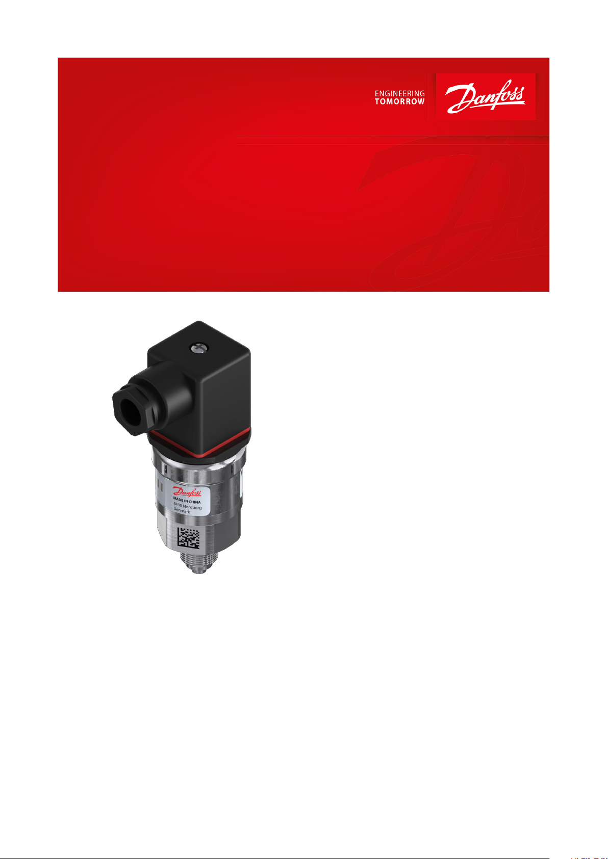
Pressure transmitter
Type MBS 3000 and MBS 3050
For general industrial purposes
The compact pressure transmitter, type MBS
3000, is designed for use in industrial and
hydraulic applications, and oers a reliable
pressure measurement, even under harsh
environmental conditions.
The compact heavy duty pressure transmitter
MBS 3050 with integrated pulse-snubber is
designed for use in hydraulic applications with
severe medium inuences like cavitation, liquid
hammer or pressure peaks and oers a reliable
pressure measurement, even under harsh
environmental conditions.
The exible pressure transmitter programme
covers dierent output signals, absolute or
gauge (relative) versions, measuring ranges
from 0 – 1 to 0 – 600 bar. A wide range of
pressure and electrical connections are
available.
Excellent vibration stability, robust
construction, and a high degree of EMC/EMI
protection equip the pressure transmitter to
meet the most stringent industrial
requirements.
AI244586497020en-001103
Page 2
1
1
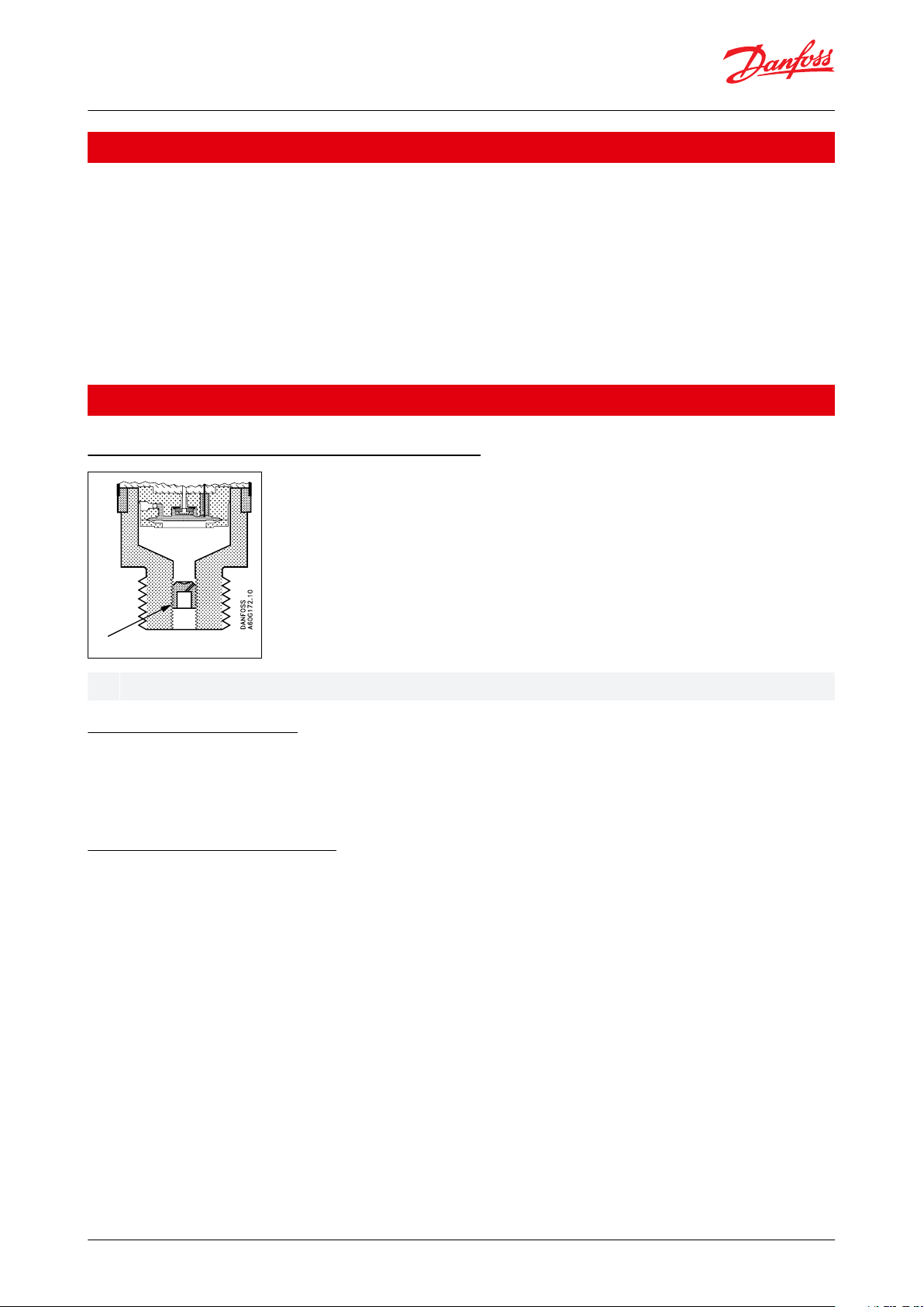
Pulse-snubber
Pressure transmitter, type MBS 3000 and MBS 3050
Features
• Designed for use in severe industrial and hydraulic environments
• Resistant to cavitation, liquid hammer and pressure peaks (MBS 3050)
• Enslosure and wetted parts of acid-resistant stainless steel (AISI 316L)
• Pressure ranges in relative (gauge) or absolute from 0 up to 600 bar
• All standard output signals: 4 – 20 mA, 0 – 5 V, 1 – 5 V, 1 – 6 V, 0 – 10 V, 1 – 10 V, Ratiometric output signal: 10-90%
of supply voltage
• A wide range of pressure and electrical connections
• Fully digitally compensated
• For use in ATEX zone 2 explosive atmospheres
• UL approved
Applications
Application and media conditions for MBS 3050
Application for MBS 3050
Cavitation, liquid hammer and pressure peaks may occur in hydraulic systems with changes in ow velocity, e.g. fast
closing of a valve or when a pump starts and stops.
The problem may occur on the inlet and outlet side of the application, even at rather low operating pressures.
Media condition for MBS 3050
Clogging of the nozzle may occur in liquids containing particles. Mounting the transmitter in an upright position
minimizes the risk of clogging, because the ow in the nozzle is limited to the start-up period until the dead volume
behind the nozzle orice is lled. The media viscosity has only little eect on the response time. Even at a viscosities
up to 100 cSt, the response time will not exceed 4 ms.
© Danfoss | Climate Solutions | 2021.06 AI244586497020en-001103 | 2
Page 3
Accuracy (incl. non-linearity, hysteresis and repeatability)
≤ ± 0.5% FS (typ.)
≤ ± 1% FS (max.)
Non-linearity BFSL (conformity)
≤ ± 0.2% FS
Hysteresis and repeatability
≤ ± 0.1% FS
Thermal zero point shift
≤ ± 0.1% FS / 10K (typ.)
≤ ± 0.2% FS / 10K (max.)
Thermal sensitivity (span) shift
≤ ± 0.1% FS / 10K (typ.)
≤ ± 0.2% FS / 10K (max.)
Response time: Liquids with viscosity < 100 cSt
< 4 ms
Response time: Air and gases (MBS 3050)
< 35 ms
Overload pressure (static)
6 × FS (max. 1500 bar)
Burst pressure
6 × FS (max. 2000 bar)
Power-up time
< 50 ms
Durability, P: 10 – 90% FS
>10 × 106 cycles
Nom. output signal (short-circuit protected)
4 – 20 mA
0 – 5, 1 – 5, 1– 6 V
0 – 10 V, 1 – 10 V
Ratiometric 10 – 90% of [UB]
Supply voltage [UB], polarity protected
9 – 32 V DC
9 – 32 V DC
15 – 32 V DC
4.5 – 5.5 V DC
Supply – current consumption
–
≤ 5 mA
≤ 8 mA
≤ 5 mA at 5 V DC
Supply voltage dependency
< 0.1% FS / 10 V
< 0.05% FS / 10 V
–
Ratiometricity
–
–
< 0.05% FS / 4.5 - 5.5 V
Output limitation
22.4 mA
0-5 V: 5.75 V
1-5 V: 5.6 V
1-6 V: 6.75 V
0-10V: 11.5 V
≈ supply voltage
Sink / Source
–
< 1 mA
Load [RL] (load connected to 0 V)
RL ≤ (UB- 9 V) / 0.02 A
RL ≥ 10 kΩ
RL ≥ 15 kΩ
RL ≥ 10 kΩ at 5 V DC
Sensor operating temperature
Normal
-40 – 85 °C
ATEX Zone 2
-10 – 85 °C
Media temperature range
-40 – 85 °C
Ambient temperature range (depending on electrical connection)
See Electrical connections
Compensated temperature range
0 – 80 °C
Transport/storage temperature range
-50 – 85 °C
EMC – Emission
EN 61000-6-3
EMC – Immunity
EN 61000-6-2
Insulation resistance
> 100 MΩ at 500 V DC
Mains frequency test
Based on SEN 361503
Vibration stability
Sinusoidal
15.9 mm-pp, 5 Hz – 25 Hz
IEC 60068-2-6
20 g, 25 Hz – 2 kHz
Random
7.5 g
rms
, 5 Hz – 1 kHz
IEC 60068-2-64
Shock resistance
Shock
500 g / 1 ms
IEC 60068-2-27
Free fall
1 m
IEC 60068-2-32
Enclosure (depending on electrical connection)
See Electrical connections
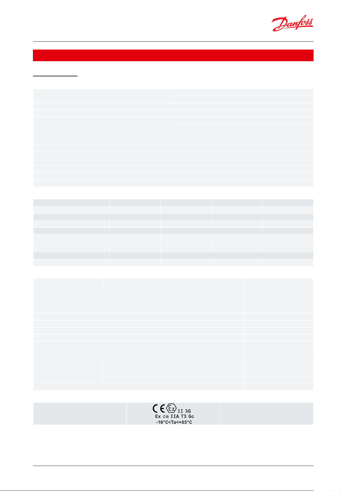
Zone 2 applications
(1)
EN60079-0; EN60079-7
Pressure transmitter, type MBS 3000 and MBS 3050
Product specication
Technical data
Table 1: Performance (EN 60770)
Table 2: Electrical specications
Table 3: Environmental conditions
Table 4: Explosive atmospheres
(1)
(1)
When used in ATEX Zone 2 areas at low temperatures the cable and plug must be protected against impact.
When used in ATEX Zone 2 areas at low temperatures the cable and plug must be protected against impact.
© Danfoss | Climate Solutions | 2021.06 AI244586497020en-001103 | 3
Page 4

Materials
Wetted parts
EN 10088-1; 1.4404 (AISI 316 L)
Enclosure
EN 10088-1; 1.4404 (AISI 316 L)
Electrical connections
See Electrical connections
Net weight (depending on pressure connection and electrical connection)
0.2 – 0.3 kg
1
)Depends on different parameters such as gasket maetrial, mating material, thread lubrication and pressure level
Type code
Type
code
A1 A3 E3 A8 A6 C8 D9 G1
AB04 AB06 AB08 AC04 AC08 GB04 FA09 FA12 FD10
Recommended
torque
1
)
30 - 35 Nm
G ¼ A
(EN 837)
¼ - 18 NPT G ¼ R
(DIN 3852-E)
9
/
16
- 18 UNF-2A
(SAE J514)
M14 x 1.5
(DIN 3852-E)
M 18 x 1.5 - 6 g
(ISO 261)
G ½ A
(EN 837)
½ - 14 NPT
G 3/8 A
(EN 837)
EN175301-803-A,
Pg 9
39.5
39.5
32
34
34
2 m screened
cable
EN 60947-5-2
M12 x 1; 4-pin
EN 175301-803-A
Pg 11
ISO 15170-A1-
3.2-SN
AMP 173065, male,
Flying leads
AMP EconosealAMP Superseal
30 - 35 Nm 30 - 35 Nm 30 - 35 Nm 30 - 35 Nm 30 - 35 Nm 30 - 35 Nm
2 - 3 turns
after finger
tightened
2 - 3 turns
after finger
tightened
Pressure transmitter, type MBS 3000 and MBS 3050
Table 5: Mechanical characteristics
Dimensions/Combinations
© Danfoss | Climate Solutions | 2021.06 AI244586497020en-001103 | 4
Page 5

Type code
A1 & A6A3E3A8C8D9G1
EN 175301-803-A,
Pg 9 & Pg 11
Danfoss
60G282
2 m screened cable
EN 60947-5-2
M12 × 1; 4-pin
AMP Superseal
1.5 series (male)
ISO 15170-A1-3.2-
Sn
Bayonet
AMP 173065, male
Flying leads 125
mm
AMP Econoseal
J series (male)
Ambient temperature
-40 – 85 °C
-30 – 85 °C
-25 – 90 °C
- 30 – 85 °C
-40 – 85 °C
-40 – 85 °C
-30 – 85 °C
Enclosure (IP
protection fullled together
with mating
connector)
IP65
IP67
IP67
IP67
IP67/IP69
IP67
IP67
Material
Glass lled polyamid, PA 6.6
(1)
Poliolyn cable
with PE shrinkage
tubing
Nickel plated brass,
CuZn/Ni
Glass lled polyamid, PA 6.6
(2)
Glass lled polyester PBT
(2)
Glass lled polyester PBT
(2)
Glass lled polyamide, PA 6.6
(1)
Electrical connection, 4 – 20
mA output (2
wire)
Pin1: + supply
Pin 2: ÷ supply
Pin 3: not used
Earth: Connected
to MBS enclosure
Brown wire: + supply
Black wire: ÷ supply
Red wire: not used
Orange: not used
Screen: not connected to MBS enclosure
Pin1: + supply
Pin 2: not used
Pin 3: not used
Pin 4: ÷ supply
Pin1: + supply
Pin 2: ÷ supply
Pin 3: not used
-
Pin 1: + supply
Pin 2: - supply
Pin 3: not used
Pin 1: + supply
Pin 2: ÷ supply/
common
Pin 3: not used
Electrical connection, 0 – 5
V, 1 – 5 V, 1 – 6
V, 0 – 10 V, 1 –
10 V output
Pin1: + supply
Pin 2: ÷ supply/
common
Pin 3: + output
Earth: Connected
to MBS enclosure
Brown wire: + output
Black wire: ÷ supply
Red wire: + supply
Orange: not used
Screen: not connected to MBS enclosure
Pin1: + supply
Pin 2: not used
Pin 3: + output
Pin 4: ÷ supply/
common
Pin1: + supply
Pin 2: ÷ supply/
common
Pin 3: + output
-
Pin 1: + supply
Pin 2: - supply
Pin 3: + output
Pin 1: + supply
Pin 2: ÷ supply/
common
Pin 3: + output
Electrical connection Ratiometric output,
10-90% of
supply voltage
Pin1: + supply
Pin 2: ÷ supply
Pin 3: output/
common
Earth: Connected
to MBS enclosure
Brown wire: output
Black wire: ÷ supply
Red wire: Common
(3)
Orange: not used
Screen: not connected to MBS enclosure
Pin1: + supply
Pin 2: not used
Pin 3: output
Pin 4: ÷ supply/
common
Pin1: + supply
Pin 2: ÷ supply
Pin 3: output/
common
Pin 1: + supply
Pin 2: ÷ supply/
common
Pin 3: + output
Pin 4: Not used
-
Pin 1: + supply
Pin 2: ÷ supply/
common
Pin 3: + output
Pressure transmitter, type MBS 3000 and MBS 3050
Electrical connections
Table 6: Electrical connections
(1)
(1)
Female plug: Glass lled polyester, PBT
Female plug: Glass lled polyester, PBT
(2)
(2)
Wire: PTFE (teon) Protection sleeve: PBT mesh (polyester)
Wire: PTFE (teon) Protection sleeve: PBT mesh (polyester)
(3)
(3)
Common
Common
© Danfoss | Climate Solutions | 2021.06 AI244586497020en-001103 | 5
Page 6

MBS 30..
– – –
Gasket / O-ring material
0
No gasket
2 Gasket, NBR -40 – 85 °C
4
O-ring, NBR -40 – 85 °C
Pressure connection
AB04
G ¼ A (EN 837) (MBS 3000 only)
AB06
G3⁄8A (EN 837) (MBS 3000 only)
Standard 0 0
AB08
G ½ A (EN 837)
With pulse-snubber 5 0
AC04
¼ – 18 NPT
AC08
½ – 14 NPT (MBS 3000 only)
Measuring range
GB04
DIN 3852-E -G ¼,
0 – 1 bar
10 FA09
DIN 3852-E-M14 x 1.5
0 – 1.6 bar
12 FA12
DIN 3852/3, M18 x 1.5-6g
0 – 2.5 bar
14
FD10
9
/16– 18 UBF - 2A (SA EJ514)
0 – 4 bar
16
0 – 6 bar
18
0 – 10 bar
20
0 – 16 bar
22
Electrical connection
Figures refer to plug
0 – 25 bar
24
0 – 40 bar
26
0 – 60 bar
28 A1
Plug Pg 9 (EN 175301-803-A)
0 – 100 bar
30 A6
Plug, Pg 11 (EN 175301-803-A)
0 – 160 bar
32 A3
Screened cable, 2 m
0 – 250 bar
34 E3
* Plug, EN 60947-5-2, M12 × 1; 4-pin; male, excl. female plug
0 – 400 bar
36 A8
* Plug, AMP Superseal 1.5 series male, excl. female plug
0 – 600 bar
38 C8
D9
G1
* Plug, AMP Econoseal, J series, male excl. female plug
Output signalPressure reference
Gauge (relative)
1 1
4 – 20 mA
Absolute
2 2
0 – 5 V
3
1 – 5 V
4
1 – 6 V
5
0 – 10 V
* Gauge versions only available as
sealed gauge versions
7
1 – 10 V
6
Preferred versions
* Plug, AMP 173065, male flying leads 125 mm excl. female plug
Ratiometric, 10 – 90%
Bayonet plug, ISO 15170-A1-3.2 Sn (Ratiometric output only)
and standard PIN configuration - see “Electrical connection”
Pressure transmitter, type MBS 3000 and MBS 3050
Ordering
Ordering standard
NOTE:
Non-standard build-up combinations may be selected. However, minimum order quantities may apply.
Please contact your local Danfoss oce for further information.
© Danfoss | Climate Solutions | 2021.06 AI244586497020en-001103 | 6
Page 7

File name
Document type
Document topic
Approval authority
060G9688.00
Manufacturers Declaration
-
Danfoss
097R0004.01
Manufacturers Declaration
RoHS
Danfoss
UA.1O146.D.00075-19
UA Declaration
EMCD/LVD
LLC CDC EURO TYSK
084R1022.01
Manufacturers Declaration
China RoHS
Danfoss
087R0017.00
Manufacturers Declaration
Simple apparatus
Danfoss
Pressure transmitter, type MBS 3000 and MBS 3050
Certicates, declarations, and approvals
The list contains all certicates, declarations, and approvals for this product type. Individual code number may have
some or all of these approvals, and certain local approvals may not appear on the list.
Some approvals may change over time. You can check the most current status at danfoss.com or contact your local
Danfoss representative if you have any questions.
Table 7: Certicates and declarations
© Danfoss | Climate Solutions | 2021.06 AI244586497020en-001103 | 7
Page 8

Online support
Danfoss oers a wide range of support along with our products, including digital product information, software,
mobile apps, and expert guidance. See the possibilities below.
The Danfoss Product Store
The Danfoss Product Store is your one-stop shop for everything product related—no matter where
you are in the world or what area of the cooling industry you work in. Get quick access to essential
information like product specs, code numbers, technical documentation, certications, accessories,
and more.
Start browsing at store.danfoss.com.
Find technical documentation
Find the technical documentation you need to get your project up and running. Get direct access to
our ocial collection of data sheets, certicates and declarations, manuals and guides, 3D models
and drawings, case stories, brochures, and much more.
Start searching now at www.danfoss.com/en/service-and-support/documentation.
Danfoss Learning
Danfoss Learning is a free online learning platform. It features courses and materials specically
designed to help engineers, installers, service technicians, and wholesalers better understand the
products, applications, industry topics, and trends that will help you do your job better.
Create your Danfoss Learning account for free at www.danfoss.com/en/service-and-support/learning.
Get local information and support
Local Danfoss websites are the main sources for help and information about our company and
products. Find product availability, get the latest regional news, or connect with a nearby expert—all
in your own language.
Find your local Danfoss website here: www.danfoss.com/en/choose-region.
Spare Parts
Get access to the Danfoss spare parts and service kit catalog right from your smartphone. The app
contains a wide range of components for air conditioning and refrigeration applications, such as
valves, strainers, pressure switches, and sensors.
Download the Spare Parts app for free at www.danfoss.com/en/service-and-support/downloads.
Any information, including, but not limited to information on selection of product, its application or use, product design, weight, dimensions, capacity or any other
technical data in product manuals, catalogues descriptions, advertisements, etc. and whether made available in writing, orally, electronically, online or via download,
shall be considered informative, and is only binding if and to the extent, explicit reference is made in a quotation or order conrmation. Danfoss cannot accept any
responsibility for possible errors in catalogues, brochures, videos and other material. Danfoss reserves the right to alter its products without notice. This also applies to
products ordered but not delivered provided that such alterations can be made without changes to form, t or function of the product. All trademarks in this material
are property of Danfoss A/S or Danfoss group companies. Danfoss and the Danfoss logo are trademarks of Danfoss A/S. All rights reserved.
© Danfoss | Climate Solutions | 2021.06 AI244586497020en-001103 | 8
 Loading...