

Page 1
Data Sheet
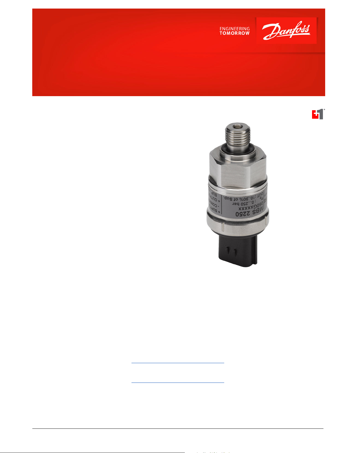
Heavy-Duty Pressure Transmitter
MBS2250 DIN
Principle of Operation
The pressure transmitter converts measured pressure
into a linear temperature compensated output signal
that is proportional to the transmitter supply voltage.
The output signal varies between 10 and 90% of the
supply voltage.
This output signal is well suited for direct connection
to an A/D converter provided that the transmitter and
the ratiometrically coupled A/D converter use the
same voltage reference. Danfoss PLUS+1® and other
microcontrollers use ratiometric A/D conversion.
Integrated Pulse Snubber
The heavy duty pressure transmitter with an
integrated pulse snubber is specially suited for
hydraulic applications where cavitation, liquid
hammer, or pressure peaks may occur. The pressure
peaks are often short but in extreme excess of the
measuring range of the transmitter.
The integrated pulse snubber is principally a nozzle in
the passage between the measured medium and the
pressure sensitive element of the transmitter
Features
•
3 pin AMP® Econoseal J-series
•
DIN pressure connection
•
PLUS+1® Compliant
•
Resistant to cavitation, liquid hammer,
and pressure peaks
•
Overload pressure 10 to 20 times
measuring range
•
Durability: >10 million cycles
•
For use in severe industrial
environments:
High vibration stability
‒
IP 67 environmental sealing
‒
Wetted parts and enclosure of acid
‒
resistant steel
•
CE marked: EMC protected in
accordance with EU EMC directive
•
Temperature compensated, linearized,
and laser calibrated
•
Ratiometric output signal: 10 to 90% of
supply voltage
Comprehensive technical literature online
at powersolutions.danfoss.com
©
Danfoss | Aug 2016 520L0801 | AI00000063en-US0402 | 1
Page 2
23
[0.906]
Ø33 [Dia1.3]
Ø11. 2
[Dia 0.44]
Ø18. 8
[Dia 0.74]
27 [1.063]
23
[0.906
]
40
[1.575]
13 [0.512]
12
[0.472]
15
[0.59]
P005 252
1
2
3
Data Sheet
MBS2250 DIN Pressure Transmitter
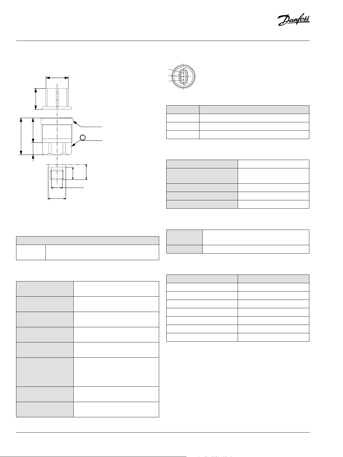
Dimensions
mm [in]
Specifications
Pressure Connection
Thread Version
DIN DIN 3852 - G 1⁄4 A, NBR O-ring 13.3 x 1.8, 630 bar [9140
psi]
AMP® Econoseal J Series (Male)
Pinout and Wiring Information
Pin Function
1 + supply
2 ÷ supply
3 Output
Electrical Characteristics
Nominal output signal 10 to 90% of V supply
Supply voltage V supply (polarity
4.75 to 8 Vdc 5 Vdc (nominal)
protected)
Power consumption < 5 mA at 5 Vdc
Output impedance < 25Ω
Load resistance RL > 5 kΩ at 5 Vdc
Mechanical Characteristics
Materials Wetted parts: DIN 17440 - 1.4404 Enclosure: (AISI 316
l)
Weight 0.2 kg [0.44 lb]
Product Part Numbers
Performance (IEC 770)
Accuracy (at reference
conditions)
Non-linearity (best fit
straight line)
Hysteresis and
repeatability
Thermal zero point shift ≤ ± 0.1% of full-scale/10k (typical); ≤ ±
Thermal sensitivity (span)
shift
Response time (liquids) 10
to 20% of full scale depending on measuring
range
Overload static and burst
pressure
Durability, P: 10 to 90% of
full-scale
2 | © Danfoss | Aug 2016 520L0801 | AI00000063en-US0402
± 0.3% of full-scale (typical); ± 1% of fullscale (maximum)
< ± 0.2% of full-scale
≤ ± 0.1% of full-scale
0.2% of full-scale/10k (maximum)
≤ ± 0.1% of full-scale/10k (typical); ≤ ±
0.2% of full-scale/10k (maximum)
< 4 ms
Maximum overload: 1500 bar; Maximum
burst: 2000 bar
> 10 million cycles
Measuring range Danfoss part number
0 to 2.5 bar [36 psi] 162U9901
0 to 40 bar [580 psi] 162U9902
0 to 160 bar [2320 psi] 162U9903
0 to 250 bar [3626 psi] 162U9904
0 to 400 bar [5800 psi] 162U9905
0 to 500 bar [7250 psi] 162U9906
0 to 600 bar [8700 psi] 162U9907
Page 3

Data Sheet
MBS2250 DIN Pressure Transmitter
Environmental Parameters
Temperature range Operating -40 to 85° C (-40 to 185° F)
Compensated 0 to 80° C (32 to 176° F)
Storage -50 to 85° C (-58 to 185° F)
EMC Emission EN 50081-1
EMC Immunity Electrostatic discharge Air mode: 8 kV Contact mode: 4 kV EN 50082-2 (IEC 801-2)
RF (field) 100 V/m 26 MHz to 1 GHz EN 50082-2 (IEC 801-3)
RF (conducted) 10 V rms 150 kHz to 30 MHz EN 50082-2 (IEC 801-6)
Transient (burst) 4 kV (CM), clamp EN 50082-2 (IEC 801-4)
Transient (surge) 1 kV (CM, DM) Rg = 42Ω EN 50082-2 (IEC 801-5)
Insulation resistance >100 MΩ at 500 Vdc
Vibration stability Sinusoidal 20 G; 25 Hz to 2 kHz IEC 68-2-6
Random 7.5 G rms; 5 Hz to 1 kHz IEC 68-2-34; IEC 68-2-36
Shock resistance Shock 500 G / 1 m IEC 68-2-27
Free fall IEC 68-2-32
Mains frequency test 500 V, 50 Hz SEN 361503
Enclosure AMP 173065-2 IP 67 - IEC 529
©
Danfoss | Aug 2016 520L0801 | AI00000063en-US0402 | 3
Page 4

Danfoss can accept no responsibility for possible errors in catalogues, brochures and other printed material. Danfoss reserves the right to alter its products without notice. This also applies to products
already on order provided that such alterations can be made without changes being necessary in specifications already agreed.
All trademarks in this material are property of the respective companies. Danfoss and the Danfoss logotype are trademarks of Danfoss A/S. All rights reserved.
4 | © Danfoss | Aug 2016 520L0801 | AI00000063en-US0402
 Loading...