

Page 1
Data sheet
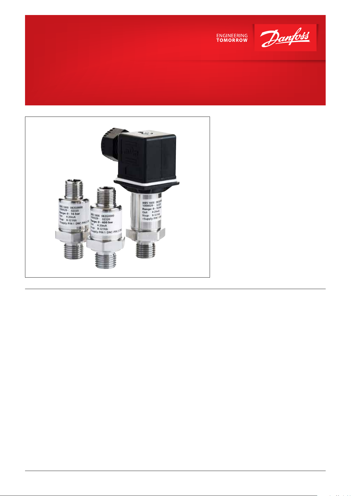
OEM Pressure transmitters for heavy-duty applications
MBS 1600 and MBS 1650
The compact OEM pressure transmitter
programme is designed for use in severe
hydraulic applications. The programme consists
of two series:
• MBS 1600 – without integrated pulse-snubber
• MBS 1650 – with integrated pulse-snubber
The integrated pulse-snubber offers a high
degree of protection against cavitations and
liquid hammer, and the well thought out design
results in excellent vibration stability and an
exceptional robustness. The high degree of EMI
protection equips the pressure transmitter to
meet most requirements.
Features • Designed for use in severe OEM applications
• For medium and ambient temperatures
up to 125 °C
• All standard output signals:
4 – 20 mA, 1 – 5 V, 1 – 6 V, 0 – 10 V
• Wetted parts made of stainless steel
• Immunity to electrical noise from VFD
• Immunity to direct coupled transients
• Immunity to pulse magnetic field
• Mis-wire protected
• Short circuit protected
• A wide range of pressure and electrical
connections
• EMC protection up to 100 V/m
• MTTFd > 100 years
© Danfoss | DCS (im) | 2020.07 520B7558 | AI204986442305en-000301 | 1
Page 2
Data sheet | OEM transmitters for heavy-duty applications, MBS 1600 and MBS 1650
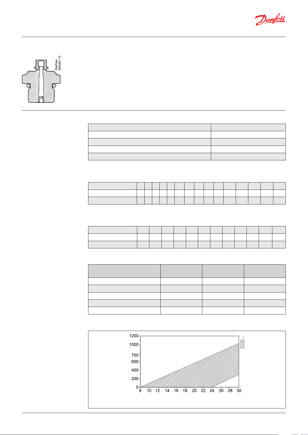
Pulse-snubber in MBS 1650 Application
Cavitation, liquid hammer and pressure peaks
may occur in liquid filled systems with changes
in flow velocity, e.g. fast closing of a valve
or pump starts and stops.
The problem may occur on the inlet and outlet
side, even at rather low operating pressures.
Technical data
Performance (EN 60770)
Accuracy (incl. nonlinearity, hysteresis and repeatability) ± 0.5% FS
Thermal zero point shift <± 0.15% FS / 10K
Thermal span shift <± 0.15% FS / 10K
Response time liquids (10 – 90%) ~ 1 ms
Durability, P: 10 – 90% FS >10 × 10
1
) Further details please contact Danfoss
Overload and burst pressure – without pulse-snubber (MBS 1600)
Nominal pressure [bar] 6 10 16 25 40 60 100 160 250 400 500 600
Overload pressure 21 30 48 80 80 140 200 320 500 800 1400 1400 2000 2500 3000
Burst pressure 280 400 640 800 800 1400 2000 1600 2500 4000 >4000 >4000 >4000 >4000 >4000
2
) Only available with M12 × 1 1.5 P high pressure port, type FC06. Please contact Danfoss.
The media viscosity has only little effect on the
response time. Even at viscosities up to 100 cSt,
the response time will not exceed 4 ms.
1
)
6
cycles
10002) 16002) 22002)
Overload and burst pressure – with integrated pulse-snubber (MBS 1650)
Nominal pressure [bar] 6 10 16 25 40 60 100 160 250 400 500 600
Overload pressure 21 30 48 120 120 210 300 480 750 1200 2100 2100
Burst pressure 280 400 640 800 800 1400 2000 1600 2500 4000 >4000 >4000
Electrical specifications
Nom. output signal
(Short-circuit protected)
Supply voltage [U
], polarity protected 8 – 32 V 8 – 32 V 12 – 32 V
B
Supply – current consumption – 4.5 mA 4.5 mA
Output impedance – ≤ 90 Ω ≤ 90 Ω
] (connected to 0 V ) See chart below RL ≥ 10 kΩ RL ≥ 10 kΩ
Load [R
L
] (connected to + V ) See chart below Not possible Not possible
Load [R
L
4 – 20 mA
(2 wire)
0 – 5 V, 1 – 5 V
1 – 6 V
0 – 10 V
4 – 20 mA output - min. / max. resistance vs. supply voltage
Note:
Loop current should not
exceed 22 mA continuous or
25 mA temporarily due to
pressure peaks
2 | AI204986442305en-000301 | 520B7558
© Danfoss | DCS (im) | 2020.07
Page 3

Data sheet | OEM transmitters for heavy-duty applications, MBS 1600 and MBS 1650
Technical data
(continued)
Environmental conditions
Media temperature range - 40 – 125 °C
Ambient temperature range See page 5
Compensated temperature range - 40 – 125 °C
Transport temperature range -55 – 150 °C
EMC EN 61326-2-3: 2013
Directive 2014/30/EU
Radiated immunity 100 Vm
Surge
Line-Earth (1 Kv - 42 ohm); Line-Line (0.5 kV42 ohm)
ESD 8 Kv contact , 15 Kv air
Vibration stability 20 g, 10 – 2000 Hz, sinus EN 60068-2-6
Shock resistance 100 g EN 60068-2-27
Enclosure (depending on electrical connection) See page 5
Mechanical conditions
Wetted parts 17 – 4 PH
Materials
Enclosure AISI 304 or plastic
Pressure connection 17 – 4 PH
Electrical connection See page 5
Ordering standard
MBS 16..
Standard
with pulse-snubber
Measuring range
0 – 6 bar
0 – 10 bar
0 – 16 bar
0 – 25 bar
0 – 40 bar
0 – 60 bar
0 – 100 bar
0 – 160 bar
0 – 250 bar
0 – 400 bar
0 – 500 bar
0 – 600 bar
0 0
5 0
1)
(Gauge)
18
2 0
2 2
2 4 G B 0 4
2 6 A C 0 4
2 8 A C 0 2
3 0 B D 0 8
3 2 A F 0 4
3 4 A F 0 2
3 6 P T 0 4
3 7
3 8
Pressure reference
Gauge(relative) 1
Output signal
4 –
20 mA
0 – 5 V
1 – 5 V
1 – 6 V
0 – 10 V
–
1
–
Gasket
Defined type
–
of pressure connection
Pressure connections (HEX 22 mm)
2
G ¼ A DIN 3852-E
)
¼ – 18 NPT
⁄ – 27 NPT
2
⁄ – 20 UNF-2A
)
¼ – 18 NPTF
⁄
NPTF
– 27
¼ – 19 PT
Electrical connections
C 1
M12 × 1 EN60947-5-2
K 4
M12 × 1 EN60947-5-2 vented via thread
A 0
EN175301-803-A
1
1
)
2
3
For pressure range < 10 bar or >600 bar, please contact Danfoss
2
) Incl. Viton gasket. Min. medium temperature is -25 °C
3
) Mating connector, code.no 060G0008
3
)
4
5
© Danfoss | DCS (im) | 2020.07
520B7558 | AI204986442305en-000301 | 3
Page 4

Data sheet | OEM transmitters for heavy-duty applications, MBS 1600 and MBS 1650
M12X1P
28.4
Danfoss
60G391.11
28.4
M12X1P
Danfoss
60G497
Ø19.0
12.0
Dimension/Combination
Type code C1 K4 A0
M12 × 1 EN60947-5-2 M12 × 1 EN60947-5-2 vented via thread EN175301-803-A
Vent groove
(4 places)
10.0
27.7
Danfoss
60N9018.1
Ø19.0
Note:
HEX is 22 mm
across flats.
Type code BD08 PT04 AC04 / AF04 AC02 / AF02 GB04
Recommended
2
)
torque
* For other combinations please contact Danfoss.
2)
Depends of different parameters as packing material, mating material, thread lubrication and pressure level.
7/16 – 20 UNF-2A ¼ – 19 Pt ¼ – 18 NPT / NPTF 1/8 – 27 NPT / NPTF G ¼ A DIN 3852-E
18 – 20 Nm
2 – 3 turns after fnger
tightend
2 – 3 turns after fnger
tightend
2 – 3 turns after fnger
tightend
30 – 35 Nm
4 | AI204986442305en-000301 | 520B7558
© Danfoss | DCS (im) | 2020.07
Page 5

Electrical connections
Type code C1/K4 A0
1
Danfoss
60N9019.1
4
2
3
Ambient temperature
4 – 20 mA
Ambient temperature,
0 – 5 V, 1 – 5 V,
1 – 6 V, 0 – 10 V,
Enclosure
(IP protection fulfilled together with mating
connector)
Material
Electrical connections,
4 – 20 mA (2 wire)
Electrical connections,
0 – 5 V, 1 – 5 V,
1 – 6 V, 0 – 10 V,
C1: M12 × 1 EN60947-5-2
K4: M12 × 1 EN60947-5-2 vented via thread
- 40 – 100 °C - 40 – 100 °C
- 40 – 125 °C - 40 – 125 °C
IP67
IP54 with vented thread
SS, PBT 30% GFR
Gold (Au) plated
Pin 1: + supply
Pin 2: do not connect
Pin 3: ÷ supply
Pin 4: do not connect
Pin 1: + supply
Pin 2: output
Pin 3: ÷ supply
Pin 4: do not connect
EN175301-803-A
IP65
Glass filled PBT 30%
Tin (Sn) plated
Pin 1: + supply
Pin 2: do not connect
Pin 3: - supply connect
Pin 4: do not connect
Pin 1: +
Pin 2: output
Pin 3: - supply
Pin 4: do not connect
© Danfoss | DCS (im) | 2020.07 520B7558 | AI204986442305en-000301 | 5
 Loading...