

Page 1
Data sheet
OEM Dual output Transmitters for heavy-duty
applications, Type MBS 1300 and MBS 1350
MBS 1300 Series is a dual output transmitter.
Output 1 gives a pressure signal where as output
2 gives a temperature signal. The Series consists
of two versions:
• MBS 1300 – without integrated
pulse-snubber
• MBS 1350 – with integrated
pulse-snubber
The integrated pulse-snubber oers a high
degree of protection against cavitations
and liquid hammer, and the well thought
out design results in excellent vibration stability
and an exceptional robustness. The high degree
of EMI protection equips the pressure transmitter
to meet most requirements.
Features
Approvals
y Designed for use in severe OEM applications
y For medium and ambient temperatures
up to 125 °C
y All standard output signals:
1 – 5 V, 1 – 6 V,
10 – 90% ratiometric voltage
y Wetted parts made of stainless steel
UL 508 recognized
ISO 7637 pulse 1 - 4
y A wide range of pressure and electrical
connections
y EMC protection up to 100 V/m
© Danfoss | DCS (im) | 2016.06
IC.PD.P21.H4.02 / 520B5583
Page 2
Data sheet | OEM Dual output Transmitters for heavy-duty applications, type MBS 1300 and MBS 1350
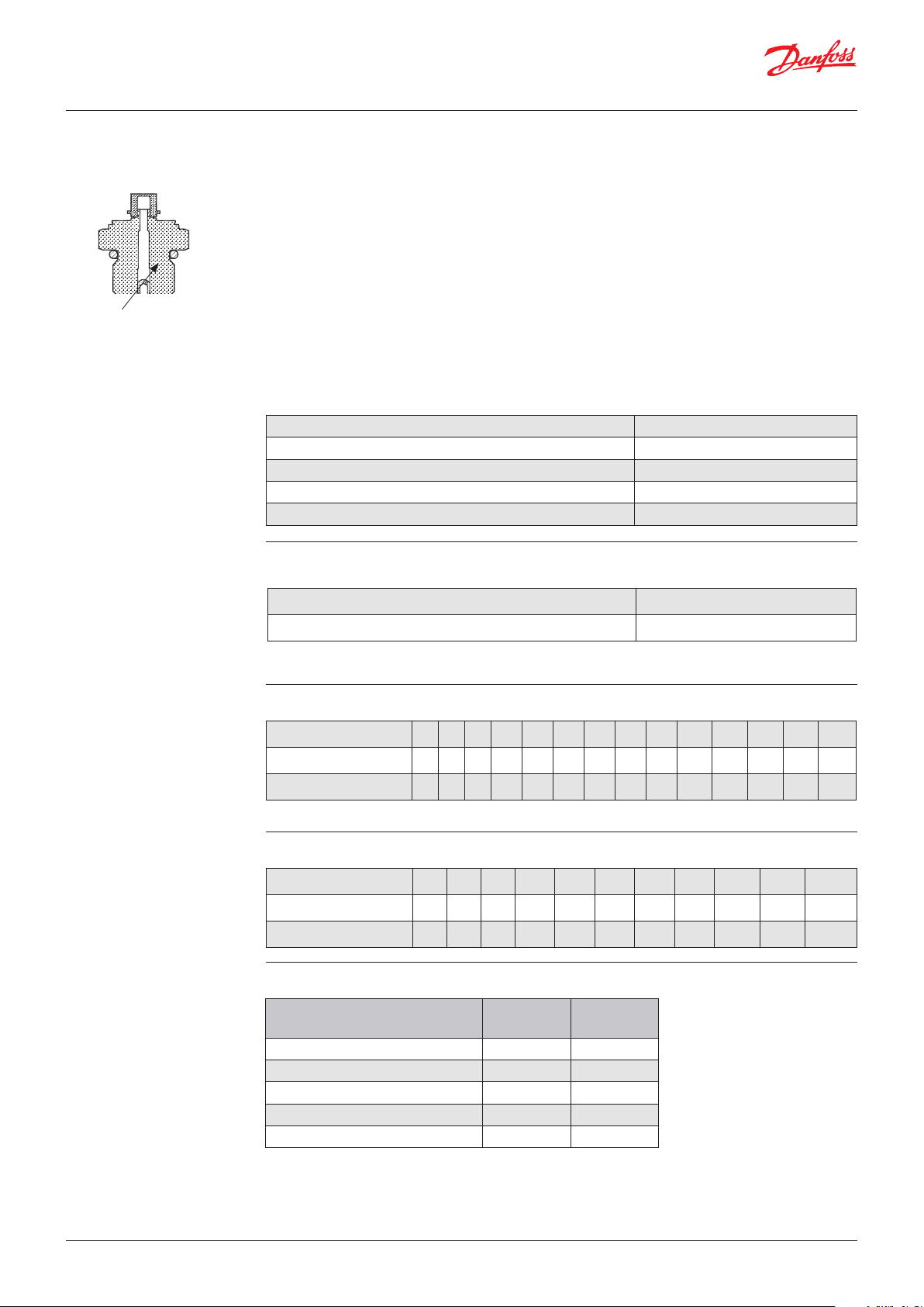
Pulse-snubber in MBS 1350
Application
Cavitation, liquid hammer and pressure peaks may occur in
liquid lled systems with changes
in ow velocity, e.g. fast closing of a valve
or pump starts and stops.
The problem may occur on the inlet and outlet side, even at
rather low operating pressures.
Pulse-snubber
The media viscosity has only little eect on the response
time. Even at viscosities up to 100 cSt, the response time will
not exceed 4 ms.
Technical data
Performance (EN 60770)
Pressure measurement
Accuracy (incl. nonlinearity, hysteresis and repeatability) ± 0.5% FS
Thermal zero point shift <± 0.15% FS/10K
Thermal span shift <± 0.15% FS/10K
Response time liquids (10 – 90%) > 0.5 ms
Durability, P: 10 – 90% FS >10 × 106 cycles
Temperature measurement
Accuracy @ 20 °C ± 0.5% FS
TEB - 20 – 80 °C ± 3.0% FS*
* As the temperature is measured on the thinlm element, the true response to uid temperature depends on the installation
details, such as the "bulk metal" surrounding e.g. manifold.
Overload and burst pressure – without pulse-snubber (MBS 1300)
Nominal pressure [bar] 10 16 25 40 60 100 160 250 400 500 600 1000* 1600* 2200*
Overload pressure 30 48 80 80 140 200 320 500 800 1400 1400 2000 2500 3000
Burst pressure 400 640 800 800 1400 2000 1600 2500 4000 >4000 >4000 >4000 >4000 >4000
* Only available with M12 × 1 1.5 P high pressure port, type FC06. Please contact Danfoss.
© Danfoss | DCS (im) | 2016.06
Overload and burst pressure – with integrated pulse-snubber (MBS 1350)
Nominal pressure [bar] 10 16 25 40 60 100 160 250 400 500 600
Overload pressure 30 48 120 120 210 300 480 750 1200 2100 2100
Burst pressure 400 640 800 800 1400 2000 1600 2500 4000 >4000 >4000
Electrical specications*
Nom. output signal
(Short-circuit protected)
Supply voltage [UB], polarity protected 8 – 30 V 5 V ± 0.5 V
Supply – current consumption 4.5 mA 4.5 mA
Output impedance ≤ 90 Ω ≤ 90 Ω
Load [RL] (connected to 0 V ) RL ≥ 10 kΩ R
Load [RL] (connected to + V ) Not possible RL ≥ 5 kΩ
* 4 – 20 mA and any output 0 – XX V not possible!
1 – 5
1 – 6 V
10 – 90%
ratiometric
L
≥ 5 kΩ
IC.PD.P21.H4.02 / 520B5583
Page 3
Data sheet | OEM Dual output Transmitters for heavy-duty applications, type MBS 1300 and MBS 1350
Technical data
Environmental conditions
Media temperature range - 40 – 125 °C
Ambient temperature range See page 6
Compensated temperature range - 40 – 125 °C
Transport temperature range -55 – 150 °C
EMC – Emission EN 61326-2-3
EMC Directive 2004/108/Ec
EMC – Immunity RF field
Electrical performance comply with ISO 7637 pulse 1 – 4, 24 V
Vibration stability 20 g, 10 – 2000 Hz, sinus EN 60068-2-6
Shock resistance 100 g EN 60068-2-27
Enclosure (depending on electrical connection) See page 6
100 V/m, 26 Mhz – 1 Ghz
EN 61326-2-3 Cable < 30 m
3 V/m, 1.4 GHz – 2.7 GHz
Mechanical conditions
Wetted parts 17 – 4 PH
Materials
Enclosure AISI 304 or plastic
Pressure connection 17 – 4 PH
Electrical connection See page 6
© Danfoss | DCS (im) | 2016.06
IC.PD.P21.H4.02 / 520B5583
Page 4
Data sheet | OEM Dual output Transmitters for heavy-duty applications, type MBS 1300 and MBS 1350
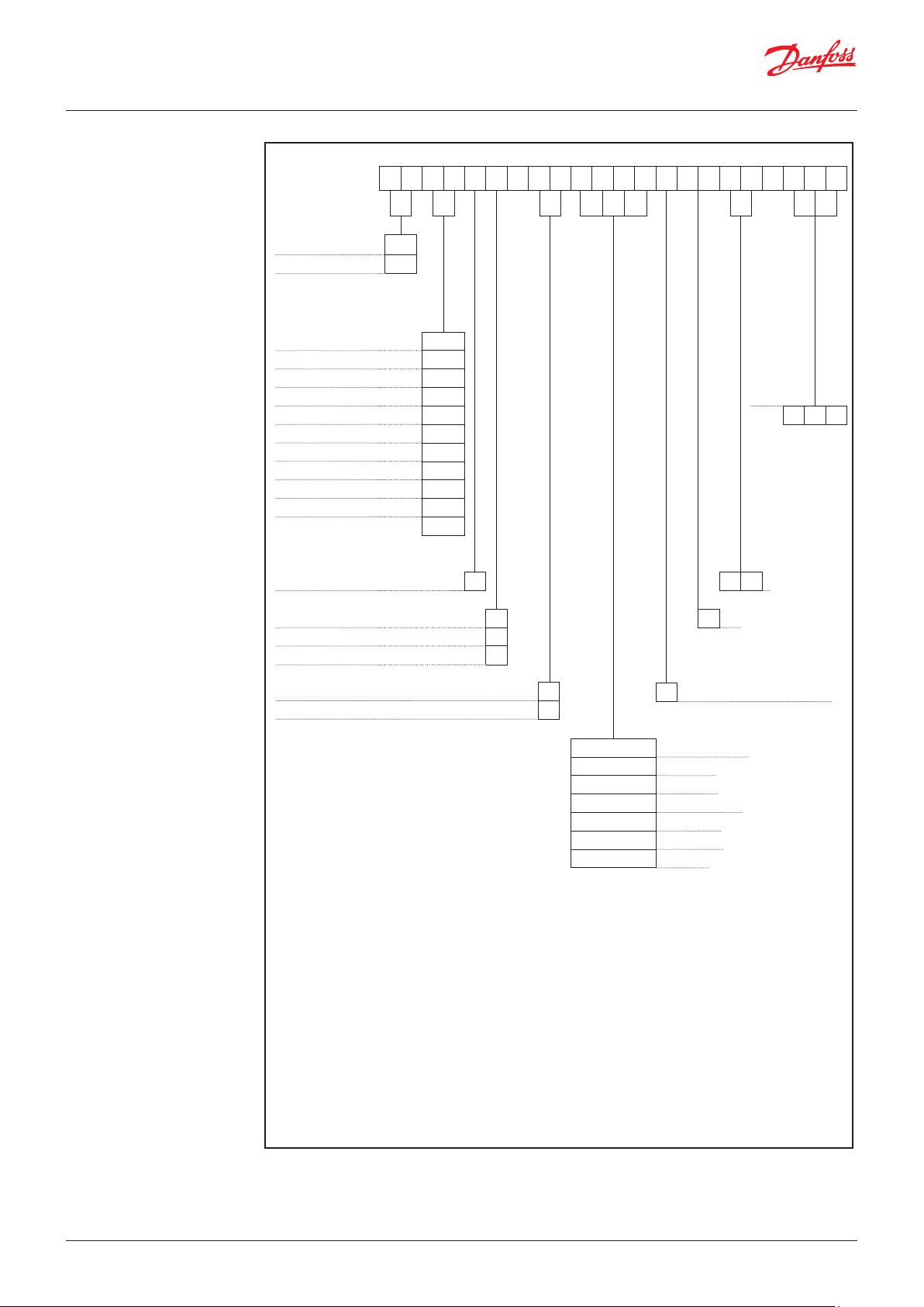
Ordering standard
MBS 13..
Standard
with pulse-snubber
Measuring range 1) (Gauge)
0 – 10 bar
0 – 16 bar
0 – 25 bar
0 – 60 bar
0 – 100 bar
0 – 160 bar
0 – 250 bar
0 – 400 bar
0 – 500 bar
0 – 600 bar 3 8
Pressure reference
Gauge(relative)
Output signal
1 – 5 V
1 – 6 V
Ratiometric, 10 – 90%
Electrical connections
Deutsch DT04-4P
0 0
5 0
2 0
2 2
2 4
2 6
2 8
3 0
3 2
3 4
3 6
3 7
—
1
—
°C
— —
Measuring
temperature
range
Max.range
80 – 125 °C
1
3
4
6
Gasket
C1
—
Defined type of pressure connectionM12 × 1 EN60947-5-2
X X
C
°C
0 – 40 bar
X X X
Min.range
- 40 – 0 °C
C3
Pressure connections (HEX 22 mm)
G B 0 4
A C 0 4
A C 0 2
B D 0 8
A F 0 4
A F 0 2
P T 0 4
G ¼ A DIN 3852-E 2)
¼ – 18 NPT
⁄ – 27 NPT
⁄ – 20 UNF-2A 2)
¼ – 18 NPTF
⁄ – 27 NPTF
¼ – 19 PT
© Danfoss | DCS (im) | 2016.06
1
)
For pressure range < 10 bar or >600 bar, please contact Danfoss
2
) Incl. Viton gasket. Min. medium temperature is -25 °C
IC.PD.P21.H4.02 / 520B5583
Page 5
Data sheet | OEM Dual output Transmitters for heavy-duty applications, type MBS 1300 and MBS 1350
38
1.9
21
14
23
M12X1P
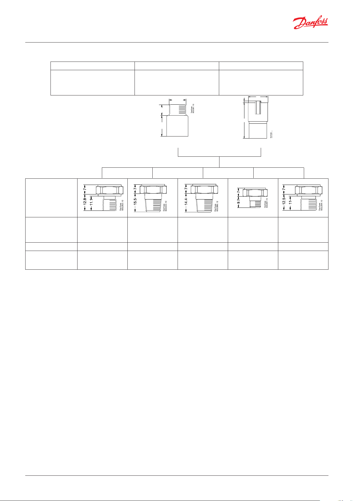
Dimensions / Combinations*
Type code C1 C3
Note:
The diameter of all
housings is 19 mm.
M12 × 1 EN60947-5-2 Deutsch DT04-4P
18.3 9.7
Note:
HEX is 22 mm
across ats.
Type code
Recommended
torque 2)
* For other combinations please contact Danfoss
2)
Depends of dierent parameters as packing material, mating material, thread lubrication and pressure level.
⁄ – 20 UNF-2A ⁄ – 19 Pt ⁄ – 18 NPT / NPTF ⁄ – 27 NPT / NPTF G ⁄ A DIN 3852-E
BD08 PT04 AC04 / AF04 AC02 / AF02 GB04
18 – 20 Nm
2 – 3 turns after fnger
tightend
2 – 3 turns after fnger
tightend
2 – 3 turns after fnger
tightend
30 – 35 Nm
© Danfoss | DCS (im) | 2016.06
IC.PD.P21.H4.02 / 520B5583
Page 6
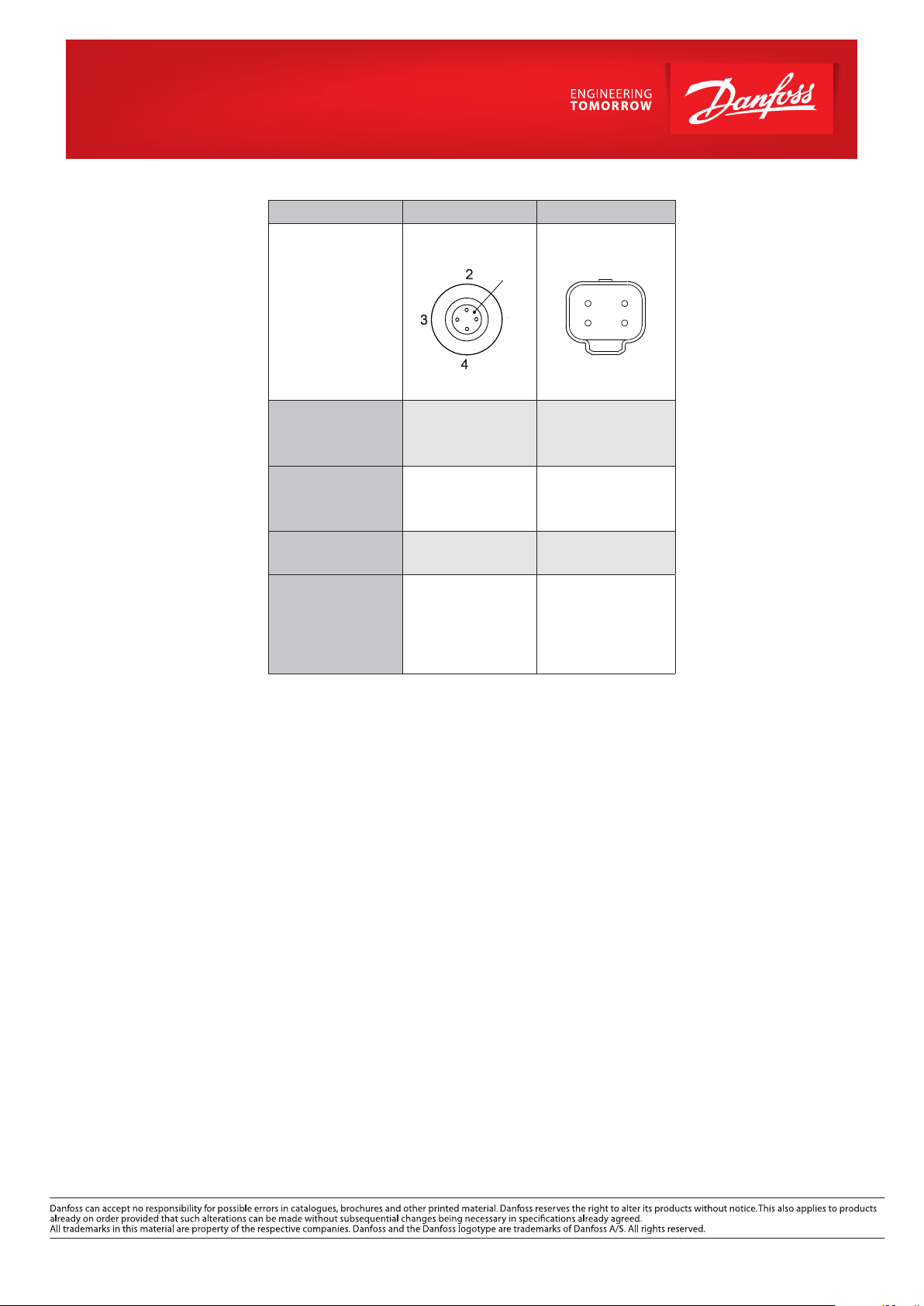
Electrical connections
14
23
Type code C1 C3
Key
M12x1 EN60947-5-2 Deutsch DT04-4P
Ambient temperature,
1 – 5 V, 1 – 6 V, ratiometric
10 – 90%
Enclosure
(IP protection fullled
together with mating
connector)
- 40 – 125 °C - 40 – 125 °C
IP67 IP67
Material
Electrical connections,
1 – 5 V, 1 – 6 V, ratiometric
10 – 90%
SS, PBT 30% GFR
Gold (Au) plated
Pin 1: + supply
Pin 2: output pressure
Pin 3: ÷ supply
Pin 4: output temperature
Glass filled PBT 30%
GFR Gold (Au) plated
Pin 1: ÷ supply
Pin 2: + supply
Pin 3: output temperature
Pin 4: output pressure
© Danfoss | DCS (im) | 2016.06
IC.PD.P21.H4.02 / 520B5583
 Loading...