

Page 1
Data Sheet
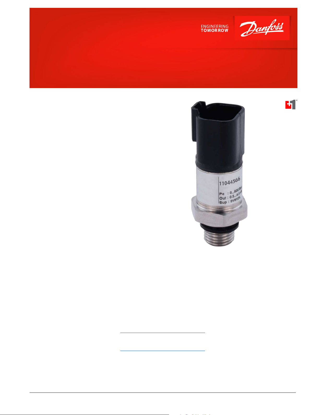
Heavy Duty Pressure Transmitter
MBS1250
Principle of Operation
The pressure transmitter converts measured pressure
into a linear temperature compensated output signal
that is proportional to the transmitter supply voltage.
The output signal varies between 10 and 90% of the
supply voltage.
This output signal is well suited for direct connection
to an A/D converter provided that the transmitter and
the ratiometrically coupled A/D converter use the
same voltage reference. Danfoss PLUS+1® and other
microcontrollers use ratiometric A/D conversion.
Integrated Pulse Snubber
The heavy duty pressure transmitter with an
integrated pulse snubber is specially suited for
hydraulic applications where cavitation, liquid
hammer, or pressure peaks may occur. The pressure
peaks are often short but in extreme excess of the
measuring range of the transmitter.
The integrated pulse snubber is principally a nozzle in
the passage between the measured medium and the
pressure sensitive element of the transmitter
Features
•
Integrated DEUTSCH DT-04 electrical
connector
•
SAE 4, SAE 6, and G1/4 pressure
connections
•
Six pressure ranges available
•
PLUS+1® Compliant
•
Resistant to cavitation, liquid hammer,
and pressure peaks
•
Overload pressure up to 3 times
measuring range
•
Durability: >10 million cycles
•
For use in severe environments
High vibration stability
‒
IP 67 environmental sealing
‒
Wetted parts and enclosure of
‒
stainless steel
•
CE marked: EMC protected in
accordance with EU EMC directive
•
Temperature compensated
•
Ratiometric output signal: 10 to 90% of
supply voltage
•
Accuracy: 0.5% full scale
Comprehensive technical literature online
at powersolutions.danfoss.com
©
Danfoss | Aug 2016 11058299 | AI00000053en-US0202 | 1
Page 2
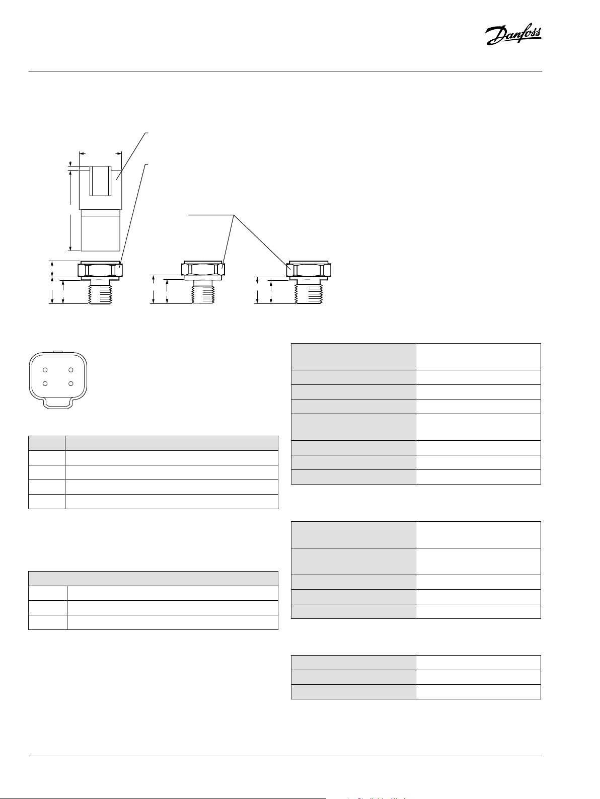
1.9 [0.075]
38.0 [1.496]
7.0 [0.275]
12.8 [0.504]
12.5 [0.492]
11.0 [0.433]
14.5 [0.571]
12.0 [0.472]
11 [0.433]
20.0 [0.787 ]
2397
Hex 22 mm SAE 4
Recommended torque:
18 to 20 N• m
[13.27 to 14.75 lb•ft]
Hex 22 mm
SAE 6 and G1/4
Recommended torque:
30 to 35 N•m
[22.12 to 25.81 lb•ft]
DEUTSCH Plug DT Series
C onnector
G1/47/16-20
UNF
9/16-18
UNF
2 3
4
1
Data Sheet
MBS1250 Pressure Transmitter
Mounting Dimensions
mm [in]
4 pin DEUTSCH Receptacle DT-04
Pinout and Wiring Information
Pin Function
1 Supply 2 Supply +
3 P. E. (not used)
*
4 Output +
*
Pin 3 connected to case; typically not used (P. E. = protective earth).
Specifications
Pressure Connection
Thread Versions
SAE 4 7/16-20 UNF-2A (SAE - 4 J514) including viton O-ring
SAE 6 9/16-18 UNF (SAE - J1926-2) including viton O-ring
G1/4 G1/4 DIN 3852-E including viton O-ring
Performance (EN 60770)
Accuracy (including nonlinearity,
hysteresis and repeatability)
Thermal zero point shift < ± 0.15% full scale/ 10K
Thermal sensitivity (span) shift < ± 0.15% full scale/ 10K
Hysteresis and repeatability < ± 0.1% full scale
Response time liquids (10 to
90%)
Overload pressure (static) 2.5 x full scale
Burst pressure > 4000 bar
Durability, P: 10 to 90% full scale >10 x 106 cycles
< ± 0.5 % full scale
< 1 ms
Electrical Characteristics
Nominal output signal (shortcircuit protected)
Supply voltage—V supply
(polarity protected)
Current consumption 4.5 mA
Load resistance (RL) RL > 5 kΩ
Output impedance RL < 90 Ω
Ratiometric 10 to 90% of supply
5 Vdc ± 0.5 Vdc
Mechanical Characteristics
Wetted parts, material 17-4PH
Enclosure material EN 10088-1 (1.4404) / AISI316L
Weight 0.2 kg
2 | © Danfoss | Aug 2016 11058299 | AI00000053en-US0202
Page 3
Data Sheet
MBS1250 Pressure Transmitter
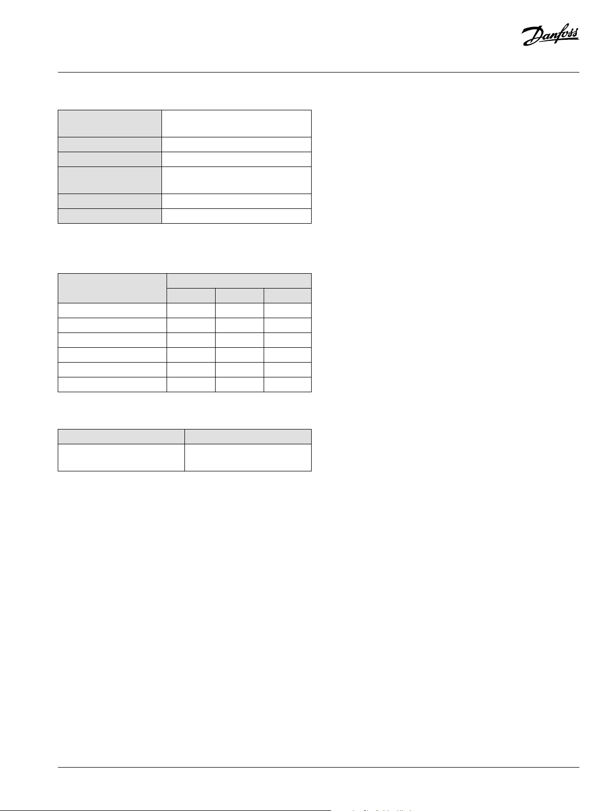
Environmental Parameters
Operating and storage
temperature range
EMC- emission EN 61000-6-3
EMC- immunity EN 61000-6-2
Vibration stability Sinusoidal, 20g, 10 Hz - 2 kHz (EN
Shock resistance 100 g (IEC 60068-2-6)
Enclosure IP 67
-40 to +125 °C [-40 to 257 °F]
60068-2-27)
Ordering Information
Pressure Connection
Measuring range Danfoss material number
SAE 4 SAE 6 G1/4
0 to 40 bar [580 psi] 11044499 11044545 11044551
0 to 160 bar [2320 psi] 11044500 11044546 11044562
0 to 250 bar [3626 psi] 11044501 11044547 11044563
0 to 400 bar [5800 psi] 11044542 11044548 11044564
0 to 500 bar [7250 psi] 11044543 11044549 11044565
0 to 600 bar [8700 psi] 11044544 11044550 11044566
Related Product
Mating connector Danfoss material number
4 pin DEUTSCH Plug DT-06-45-E003
Series bag assembly
11028348
©
Danfoss | Aug 2016 11058299 | AI00000053en-US0202 | 3
Page 4

Danfoss can accept no responsibility for possible errors in catalogues, brochures and other printed material. Danfoss reserves the right to alter its products without notice. This also applies to products
already on order provided that such alterations can be made without changes being necessary in specifications already agreed.
All trademarks in this material are property of the respective companies. Danfoss and the Danfoss logotype are trademarks of Danfoss A/S. All rights reserved.
4 | © Danfoss | Aug 2016 11058299 | AI00000053en-US0202
 Loading...