

Page 1
User Manual
PLUS+1® Compliant
MBS 1250 Pressure Sensor Function
Blocks
powersolutions.danfoss.com
Page 2

User Manual
PLUS+1® Compliant MBS 1250 Pressure Sensor Function Blocks
Revision history Table of revisions
Date Changed Rev
March 2018 Added Prs_Snsr550b and Prs_Snsr_Gen function block. 0401
April 2016 CA
November 2011 BA
2 | © Danfoss | March 2018 11062069 | AQ00000100en-US0401
Page 3

User Manual
PLUS+1® Compliant MBS 1250 Pressure Sensor Function Blocks
Contents
Prs_Snsr40b Function Block
Inputs....................................................................................................................................................................................................5
Outputs................................................................................................................................................................................................ 5
Status and Fault Logic.....................................................................................................................................................................6
Status Logic...................................................................................................................................................................................6
Fault Logic..................................................................................................................................................................................... 6
Relationship Between Function Block Input and Output Signals...................................................................................7
Function Block Connections.........................................................................................................................................................8
MC Controller—Input Configuration........................................................................................................................................ 8
Configure the MFIn.....................................................................................................................................................................9
Configure the DigAn..................................................................................................................................................................9
SC Controller—Input Configuration....................................................................................................................................... 10
Configure the MFIn..................................................................................................................................................................10
Configure the DigAn................................................................................................................................................................11
Prs_Snsr160b Function Block
Inputs..................................................................................................................................................................................................12
Outputs..............................................................................................................................................................................................13
Status and Fault Logic..................................................................................................................................................................13
Status Logic.................................................................................................................................................................................13
Fault Logic...................................................................................................................................................................................14
Relationship Between Function Block Input and Output Signals................................................................................ 14
Function Block Connections...................................................................................................................................................... 15
MC Controller—Input Configuration......................................................................................................................................15
Configure the MFIn..................................................................................................................................................................16
Configure the DigAn................................................................................................................................................................16
SC Controller—Input Configuration....................................................................................................................................... 17
Configure the MFIn..................................................................................................................................................................17
Configure the DigAn................................................................................................................................................................18
Prs_Snsr250b Function Block
Inputs..................................................................................................................................................................................................19
Outputs..............................................................................................................................................................................................20
Status and Fault Logic..................................................................................................................................................................20
Status Logic.................................................................................................................................................................................20
Fault Logic...................................................................................................................................................................................21
Relationship Between Function Block Input and Output Signals................................................................................ 21
Function Block Connections...................................................................................................................................................... 22
MC Controller—Input Configuration......................................................................................................................................22
Configure the MFIn..................................................................................................................................................................23
Configure the DigAn................................................................................................................................................................23
SC Controller—Input Configuration....................................................................................................................................... 24
Configure the MFIn..................................................................................................................................................................24
Configure the DigAn................................................................................................................................................................25
Prs_Snsr400b Function Block
Inputs..................................................................................................................................................................................................26
Outputs..............................................................................................................................................................................................27
Status and Fault Logic..................................................................................................................................................................27
Status Logic.................................................................................................................................................................................27
Fault Logic...................................................................................................................................................................................28
Relationship Between Function Block Input and Output Signals................................................................................ 28
Function Block Connections...................................................................................................................................................... 29
MC Controller—Input Configuration......................................................................................................................................29
Configure the MFIn..................................................................................................................................................................30
Configure the DigAn................................................................................................................................................................30
SC Controller—Input Configuration....................................................................................................................................... 31
Configure the MFIn..................................................................................................................................................................31
Configure the DigAn................................................................................................................................................................32
Prs_Snsr500b Function Block
©
Danfoss | March 2018 11062069 | AQ00000100en-US0401 | 3
Page 4

User Manual
PLUS+1® Compliant MBS 1250 Pressure Sensor Function Blocks
Contents
Inputs..................................................................................................................................................................................................33
Outputs..............................................................................................................................................................................................34
Status and Fault Logic..................................................................................................................................................................34
Status Logic.................................................................................................................................................................................34
Fault Logic...................................................................................................................................................................................35
Relationship Between Function Block Input and Output Signals................................................................................ 35
Function Block Connections...................................................................................................................................................... 36
MC Controller—Input Configuration......................................................................................................................................36
Configure the MFIn..................................................................................................................................................................37
Configure the DigAn................................................................................................................................................................37
SC Controller—Input Configuration....................................................................................................................................... 38
Configure the MFIn..................................................................................................................................................................38
Configure the DigAn................................................................................................................................................................39
Prs_Snsr550b Function Block
Inputs..................................................................................................................................................................................................40
Outputs..............................................................................................................................................................................................41
Status and Fault Logic..................................................................................................................................................................41
Status Logic.................................................................................................................................................................................41
Fault Logic...................................................................................................................................................................................42
Relationship Between Function Block Input and Output Signals................................................................................ 42
Function Block Connections...................................................................................................................................................... 43
MC Controller—Input Configuration......................................................................................................................................43
Configure the MFIn..................................................................................................................................................................44
Configure the DigAn................................................................................................................................................................44
SC Controller—Input Configuration....................................................................................................................................... 45
Configure the MFIn..................................................................................................................................................................45
Configure the DigAn................................................................................................................................................................46
Prs_Snsr600b Function Block
Inputs..................................................................................................................................................................................................47
Outputs..............................................................................................................................................................................................48
Status and Fault Logic..................................................................................................................................................................48
Status Logic.................................................................................................................................................................................48
Fault Logic...................................................................................................................................................................................49
Relationship Between Function Block Input and Output Signals................................................................................ 49
Function Block Connections...................................................................................................................................................... 50
MC Controller—Input Configuration......................................................................................................................................50
Configure the MFIn..................................................................................................................................................................51
Configure the DigAn................................................................................................................................................................51
SC Controller—Input Configuration....................................................................................................................................... 52
Configure the MFIn..................................................................................................................................................................52
Configure the DigAn................................................................................................................................................................53
Prs_Snsr_Gen Function Block
Inputs..................................................................................................................................................................................................54
Outputs..............................................................................................................................................................................................54
Status and Fault Logic..................................................................................................................................................................55
Status Logic.................................................................................................................................................................................55
Fault Logic...................................................................................................................................................................................55
Relationship Between Function Block Input and Output Signals................................................................................ 56
Function Block Connections...................................................................................................................................................... 57
MC Controller—Input Configuration......................................................................................................................................57
Configure the MFIn..................................................................................................................................................................58
Configure the DigAn................................................................................................................................................................58
SC Controller—Input Configuration....................................................................................................................................... 59
Configure the MFIn..................................................................................................................................................................59
Configure the DigAn................................................................................................................................................................60
4 | © Danfoss | March 2018 11062069 | AQ00000100en-US0401
Page 5
User Manual
PLUS+1® Compliant MBS 1250 Pressure Sensor Function Blocks
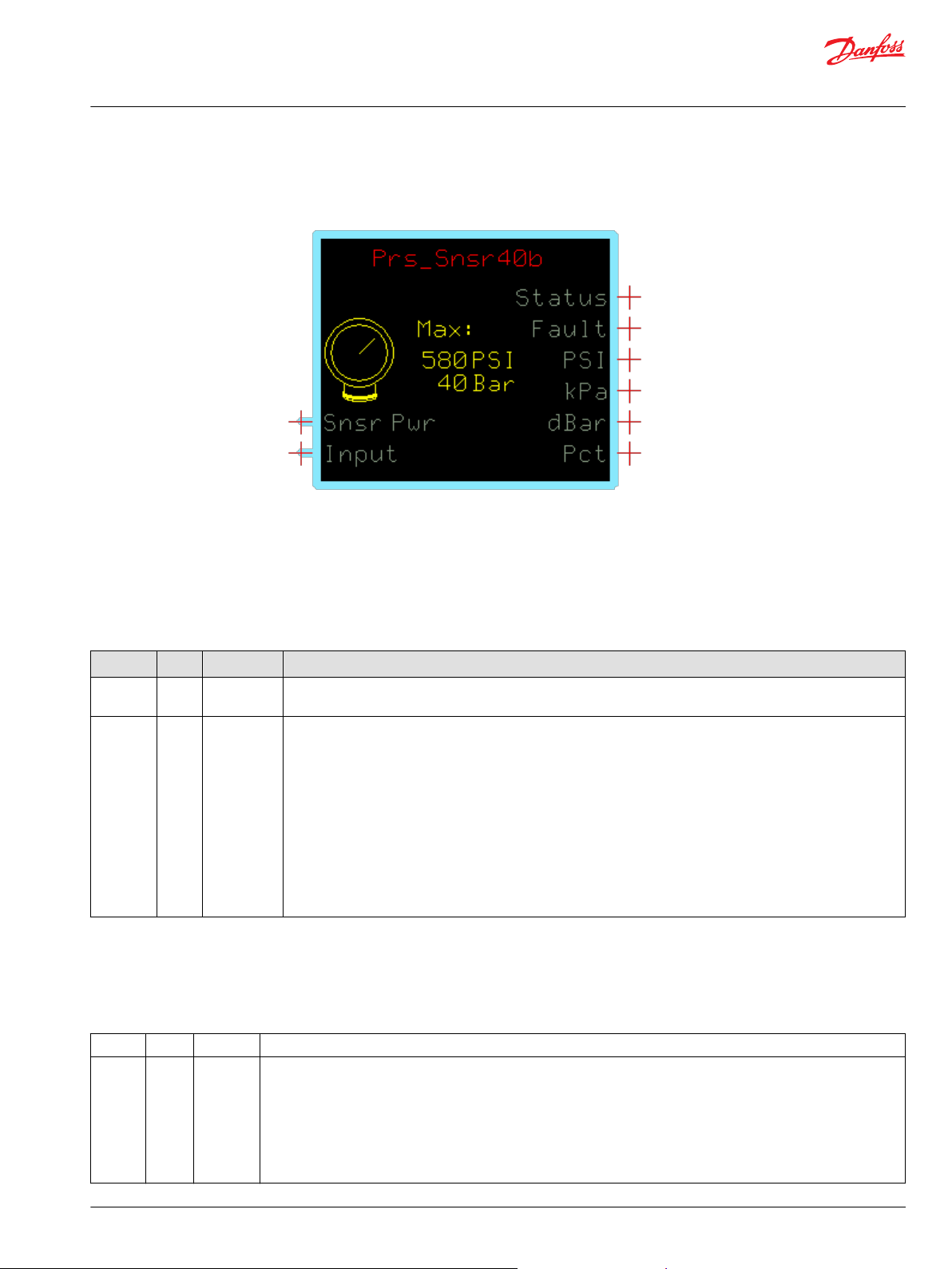
Prs_Snsr40b Function Block
This function block configures the output of MBS 1250 pressure sensors with a nominal 0–40 bar [4000
kPa/580 PSI] range.
Inputs
Find out how the function block uses a reference voltage and a changing input voltage to produce PSI,
kPa, dBar and Pct outputs.
Function Block Inputs
Input Type Range Description
Snsr Pwr U16 0–5250 mV Inputs a reference voltage that the PLUS+1® controller also applies to the Pin 1 (+ Supply) on the pressure
transmitter.
Input U16 0–5250 mV The function block compares the changing Input voltage with the constant Snsr Pwr reference voltage to produce
PSI, kPa, dBar and Pct outputs.
The function block’s nominal operating range is between 10.00% and 90.00% of Snsr Pwr voltage.
When the Input voltage reaches:
•
10.00% of the Snsr Pwr voltage, the function block’s output starts rising above zero.
•
90.00% of the Snsr Pwr voltage, the function block outputs its maximum nominal outputs of PSI and kPa. The
maximum nominal output is specified by Bar and is limited to 2200.
•
100.00% of the Snsr Pwr voltage, the function block outputs its maximum over-pressure outputs of PSI and kPa
at 112.50% of the output defined by Bar.
The maximum over-pressure output equals 112.50% of the maximum nominal output. The generic function
block allows you to specify the pressure range allowed.
Outputs
Learn how the outputs of the general function block work.
Function Block Outputs
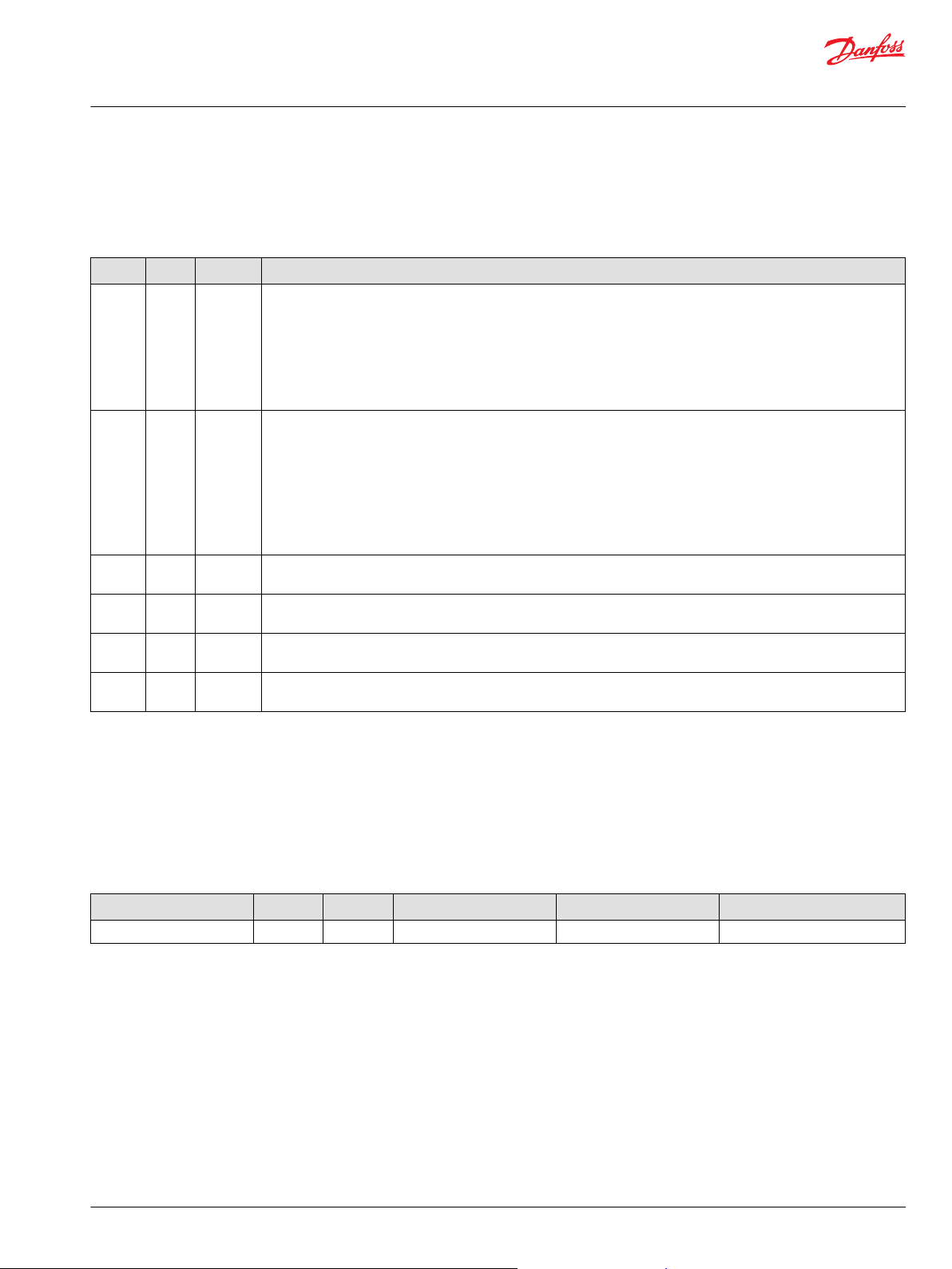
Output Type Range Description
Status U16 —— Indicates if the Flt Pct value is within range or is set too high.
The Flt Pct sets the percentage that the Input voltage can rise above or fall below the function block’s operating range
without setting a fault condition.
You can change the Flt Pct value (1000 = 10.00%) on the inner page of the Prs_Snsr function block.
The Status output uses the bitwise scheme.
•
0x0000 = Block is OK.
•
0x8008 = Flt Pct value is too high.
©
Danfoss | March 2018 11062069 | AQ00000100en-US0401 | 5
Page 6

User Manual
PLUS+1® Compliant MBS 1250 Pressure Sensor Function Blocks
Prs_Snsr40b Function Block
Function Block Outputs (continued)
Fault U16 —— Indicates if the voltage on the function block’s Input pin is too low or too high.
The Flt Pct sets the percentage that the Input voltage can rise above or fall below the function block’s operating range
without setting a fault condition.
You can change the Flt Pct value (1000 = 10.00%) on the inner page of the Prs_Snsr function block.
The Fault output uses the bitwise scheme.
•
0x0000 = Block is OK.
•
0x8001 = Input value is too low.
•
0x8002 = Input value is too high.
PSI U16 0–35896 Indicates pressure in pounds per square inch (PSI).
1 = 1 PSI.
kPa U16 0–247500 Indicates pressure in kilopascals (kPa).
1 = 1 kPa.
dBar U16 0–24750
Pct U16 0–11250 Indicates pressure as a percent of the function block’s operating range.
Indicates pressure in decibars (dBar).
1 = 1 dBar.
10000 = 100.00%.
Status and Fault Logic
This topic describes how status logic and fault logic are indicated for the function block.
Status Logic
The status code indicates the calibration state of the function block.
Status logic
Condition Hex
Invalid setup. 0x8008 1000 Flt Pct > 1000 (10.00%). Output = 0. Reduce Flt Pct.
*
Bit 16 set to 1 identifies a standard Danfoss status or fault code.
*
Binary Cause Response Correction
Fault Logic
Learn how fault logic can indicate problems, causes of problems, and solutions.
Fault logic
Condition Hex
Input value is too low. 0x8001 0001
Input value is too high. 0x8002 0010
*
Bit 16 set to 1 identifies a standard Danfoss status or fault code.
*
Binary Cause Response Correction
Volt(age) is less than [10% of
Snsr Pwr] - [Flt Pct of nominal
signal range (which is 80% of
Snsr Pwr)].
Snsr Pwr less than 0. Ensure correct software input is
Volt(age) is greater than [90% of
Snsr Pwr] + [Flt Pct of nominal
signal range (which is 80% of
Snsr Pwr)].
Snsr Pwr greater than 5250.
Output = 0.
Output is extrapolated beyond
the maximum value up to 11250
(112.50%).
Output = 0.
Inspect for open circuit in wire
connections to sensor.
made in the application.
Inspect for short circuit in wire
•
connections to sensor.
Verify the correct pressure
•
sensor is used for the
application.
Ensure correct software input is
made in the application.
6 | © Danfoss | March 2018 11062069 | AQ00000100en-US0401
Page 7
User Manual
PLUS+1® Compliant MBS 1250 Pressure Sensor Function Blocks
Prs_Snsr40b Function Block
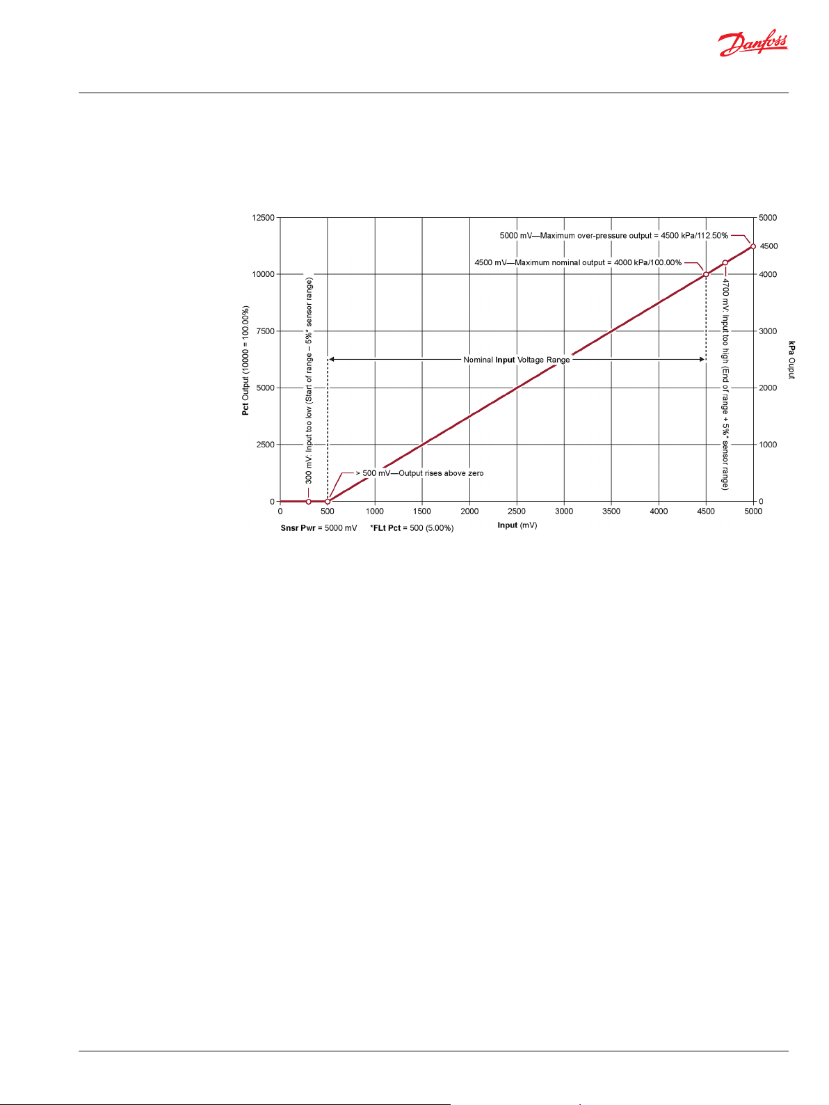
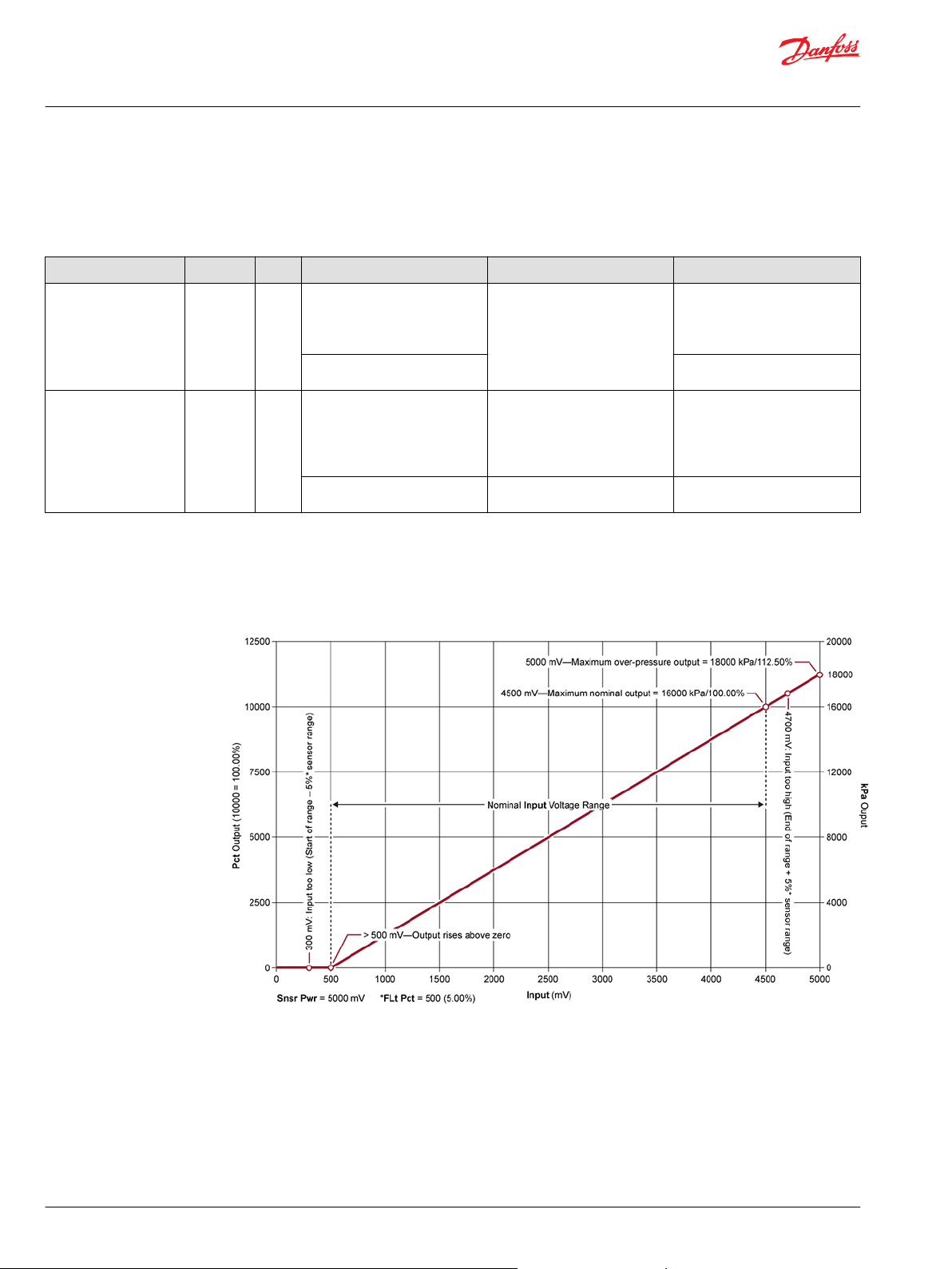
Relationship Between Function Block Input and Output Signals
Use the plot to find out the relationships between the function block's Input voltages and its kPa and Pct
outputs.
This function block’s:
Flt Pct value = 500 (5.00%) and its Snsr Pwr value = 5000 mV.
•
Nominal Input voltage ranges between 10.00% (500 mV) and 90.00% (4500 mV) of the Snsr Pwr
•
voltage.
Nominal pressure output ranges between zero with the Input voltage at 500 mV and a maximum
•
nominal 4000 kPa/100.00% with the Input voltage at 4500 mV.
Maximum over-pressure output = 4500 kPa with the Input voltage at 5000 mV. (4000 maximum
•
nominal pressure x 112.50% = 4500 kPa maximum over-pressure)
When the Input voltage:
•
Drops below 300 mV, the function block outputs an input too low fault. (500 mV – 5% of the 4000 mV
nominal input voltage range = fault at 300 mV)
•
Rises above 4700 mV, the function block outputs an input too high fault. (4500 mV + 5% of the 4000
mV nominal input voltage range = fault at 4700 mV)
©
Danfoss | March 2018 11062069 | AQ00000100en-US0401 | 7
Page 8
User Manual
PLUS+1® Compliant MBS 1250 Pressure Sensor Function Blocks
Prs_Snsr40b Function Block
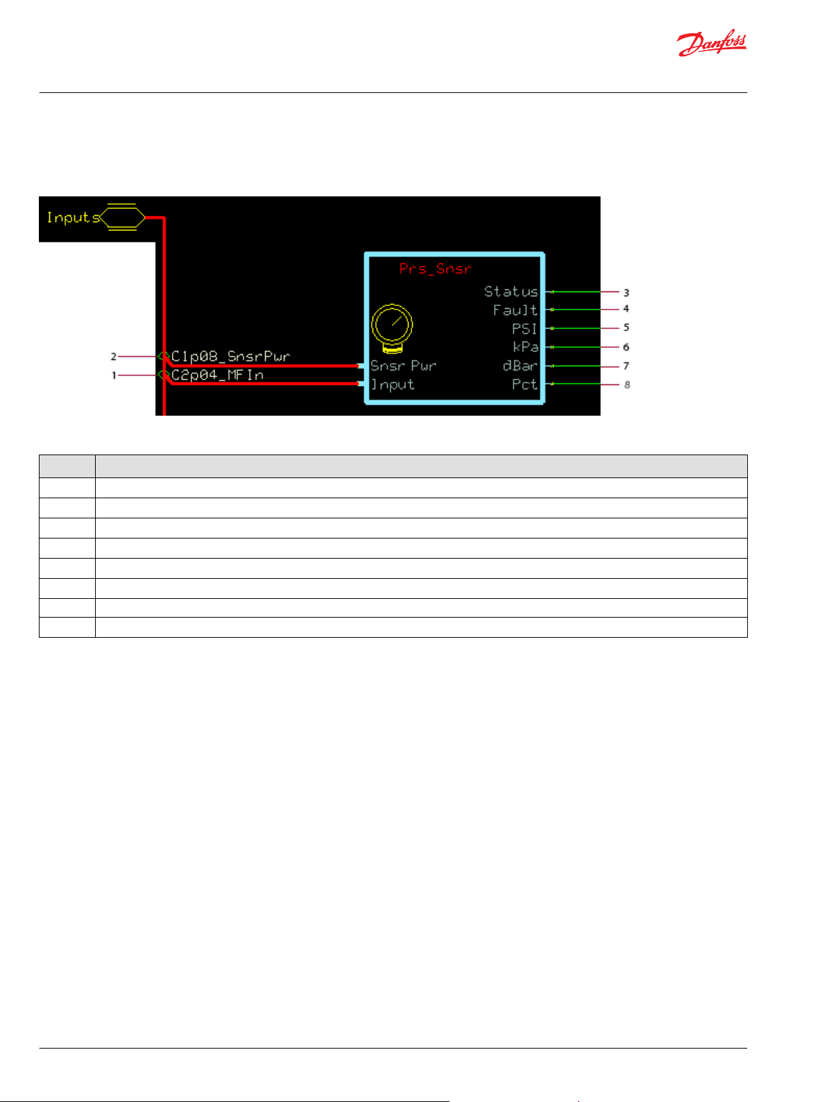
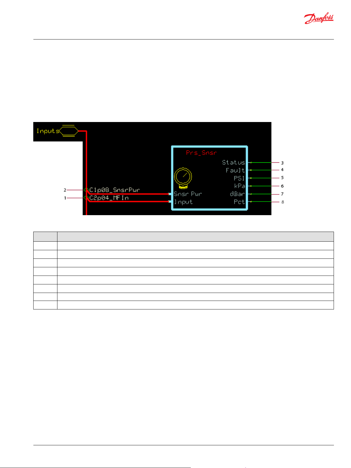
Function Block Connections
Connections you can make with the function block are described.
Function block connections
Item Description
1 Sensor voltage (varies with pressure).
2 Sensor reference power voltage.
3 Function block status.
4 Function block faults.
5 Pressure in PSI.
6 Pressure in kPa.
7 Pressure in decibar (dBar)
8 Pressure in % of range.
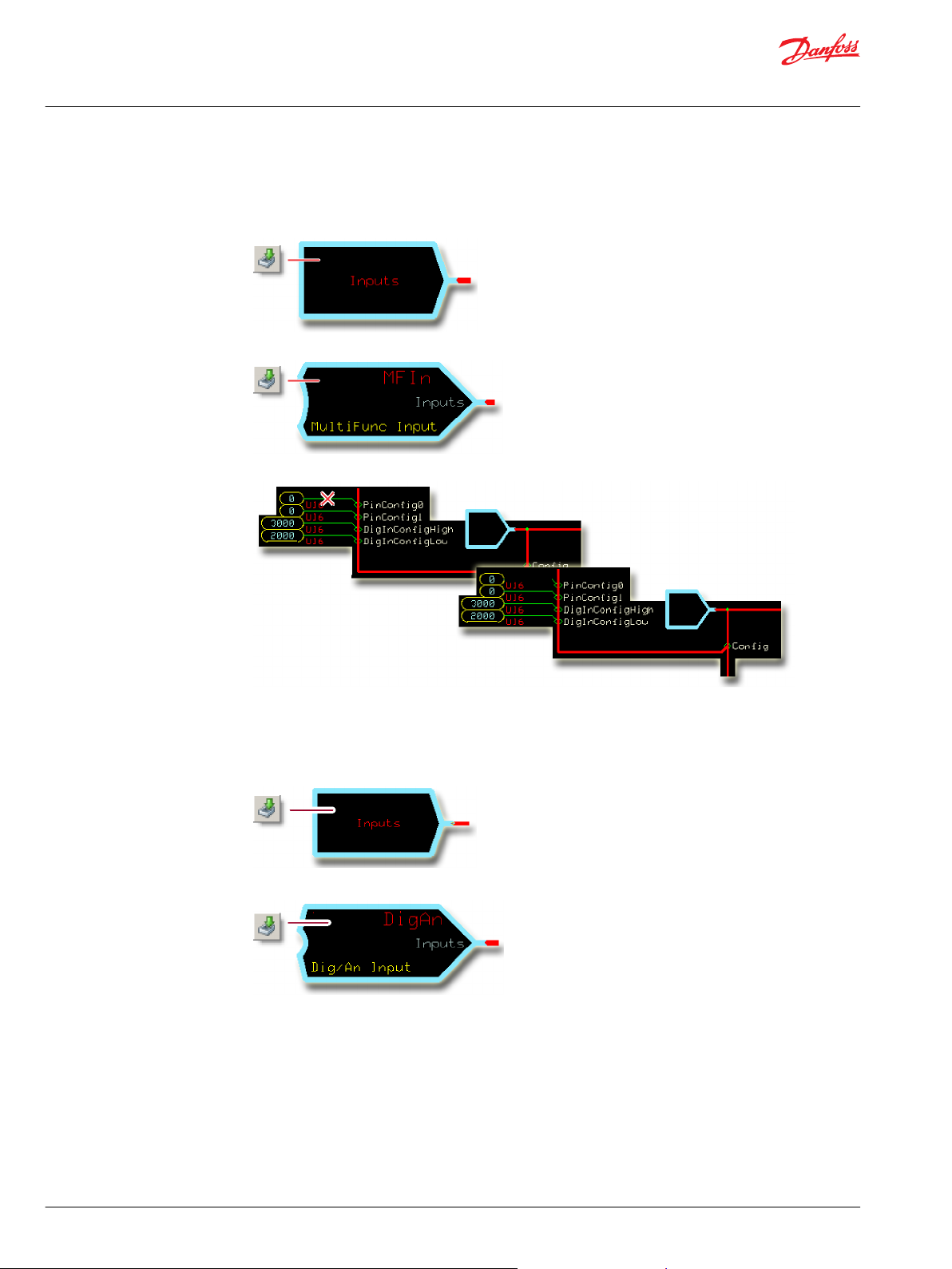
MC Controller—Input Configuration
Configure MFIn and DigAn to accept the input of the function block.
For MC Controllers, you route the function block’s Input through an MFIn or a DigAn.
You must change the MFIn and DigAn default configurations to accept this input.
8 | © Danfoss | March 2018 11062069 | AQ00000100en-US0401
Page 9
User Manual
PLUS+1® Compliant MBS 1250 Pressure Sensor Function Blocks
Prs_Snsr40b Function Block
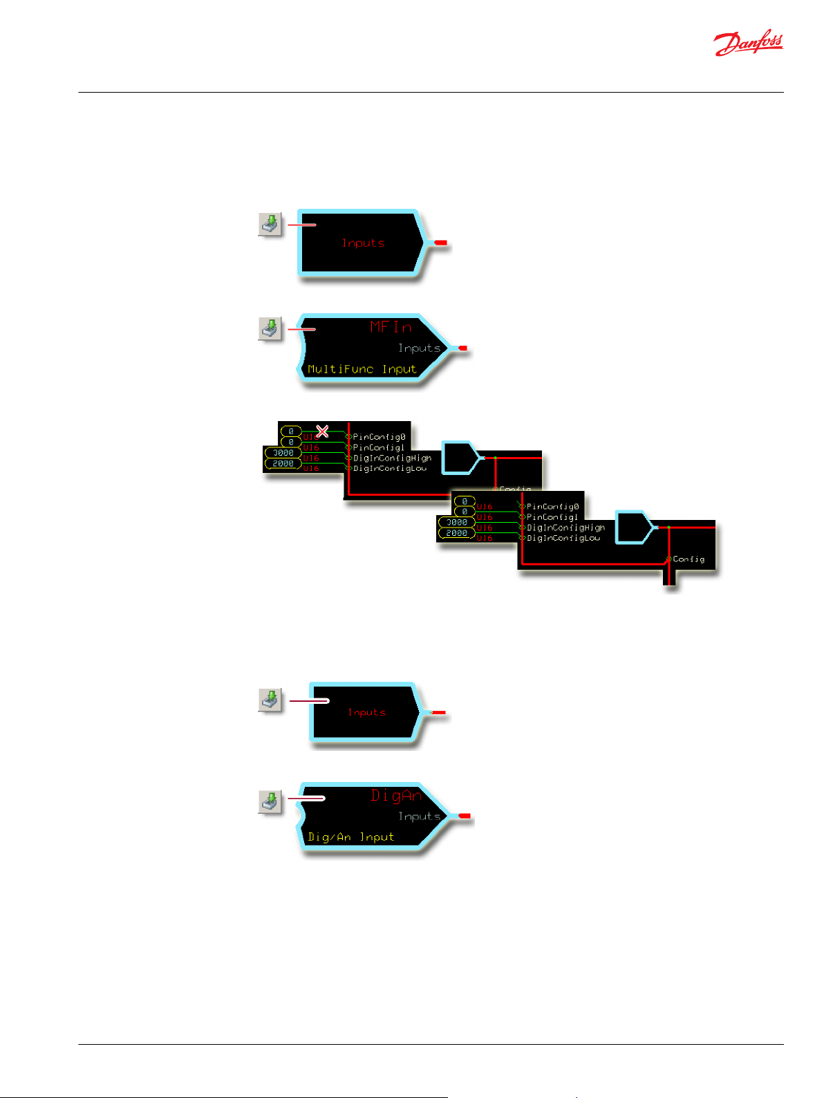
Configure the MFIn
Learn how to configure MFIn to accept input from the function block.
1. In the GUIDE template, enter the Inputs page.
2. Enter the MFIn that receives the input.
3. Make the changes that are shown in this figure.
Configure the DigAn
Learn how to configure DigAn to accept input.
1. In the GUIDE template, enter the Inputs page.
2. Enter the page that receives the input.
©
Danfoss | March 2018 11062069 | AQ00000100en-US0401 | 9
Page 10
User Manual
PLUS+1® Compliant MBS 1250 Pressure Sensor Function Blocks
Prs_Snsr40b Function Block
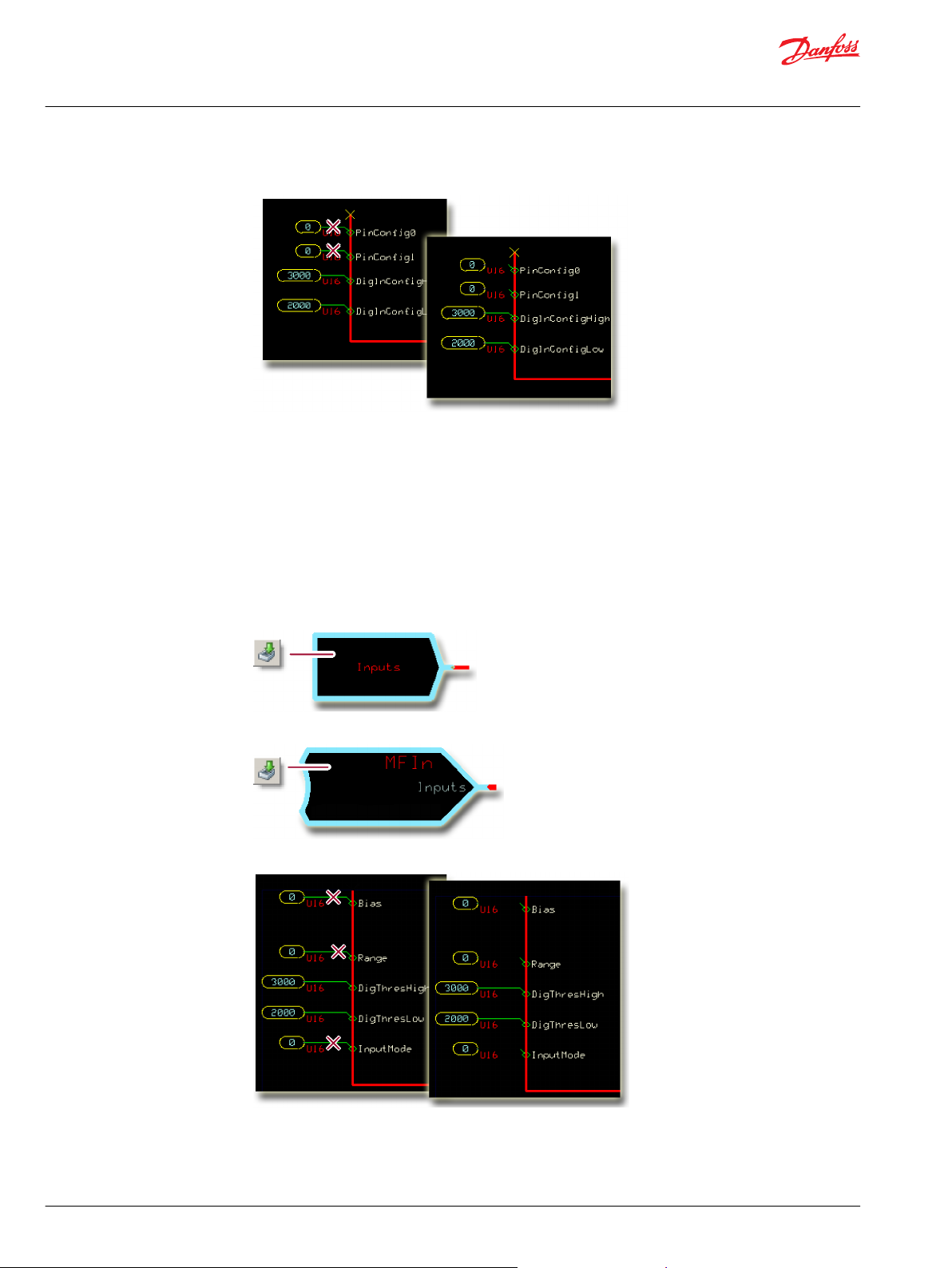
3. Make the changes that are shown in the following figure.
SC Controller—Input Configuration
Configure MFIn and DigAn to accept the input of the function block.
You route the function block’s Input through an MFIn or a DigAn. You must change the MFIn and
DigAn default configurations to accept this input.
Configure the MFIn
Learn how to configure MFIn to accept input from the function block.
1. In the GUIDE template, enter the Inputs page.
2. Enter the page that receives the input.
3. Make the changes that are shown in the following figure.
10 | © Danfoss | March 2018 11062069 | AQ00000100en-US0401
Page 11
User Manual
PLUS+1® Compliant MBS 1250 Pressure Sensor Function Blocks
Prs_Snsr40b Function Block
Configure the DigAn
Learn how to configure DigAn to receive input from the function block.
1. In the GUIDE template, enter the Inputs page.
2. Enter the page that receives the input.
3. Make the changes that are shown in the following figure.
©
Danfoss | March 2018 11062069 | AQ00000100en-US0401 | 11
Page 12
User Manual
PLUS+1® Compliant MBS 1250 Pressure Sensor Function Blocks
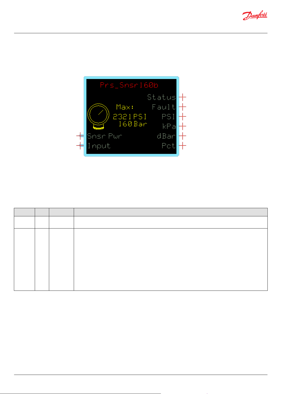
Prs_Snsr160b Function Block
This function block configures the output of MBS 1250 pressure sensors with a nominal 0–160 bar [16000
kPa/2320 PSI] range.
Inputs
Find out how the function block uses a reference voltage and a changing input voltage to produce PSI,
kPa, dBar and Pct outputs.
Function Block Inputs
Input Type Range Description
Snsr Pwr —— 0–5250 mV Inputs a reference voltage that the PLUS+1 controller also applies to the Pin 1 (+ Supply) on the Pressure
Transmitter.
Input —— 0–5250 mV The function block compares the changing Input voltage with the constant Snsr Pwr reference voltage to produce
PSI, kPa, dBar, and Pct outputs.
The function block’s nominal operating range is between 10.00% and 90.00% of Snsr Pwr voltage.
When the Input voltage reaches:
•
10.00% of the Snsr Pwr voltage, the function block’s output starts rising above zero.
•
90.00% of the Snsr Pwr voltage, the function block outputs its maximum nominal outputs of 2320 PSI/16000
kPa/10000 (100.00%).
•
100.00% of the Snsr Pwr voltage, the function block outputs its maximum over-pressure outputs of 2610 PSI/
18000 kPa/11250 (112.50%).
The maximum over-pressure output equals 112.50% of the maximum nominal output (16000 kPa x 112.50% =
18000 kPa).
12 | © Danfoss | March 2018 11062069 | AQ00000100en-US0401
Page 13
User Manual
PLUS+1® Compliant MBS 1250 Pressure Sensor Function Blocks
Prs_Snsr160b Function Block
Outputs
Learn about the outputs of the Prs_Snsr160b function block.
Function Block Outputs
Output Type Range Description
Status U16 —— Indicates if the Flt Pct value is within range or is set too high.
The Flt Pct sets the percentage that the Input voltage can rise above or fall below the function block’s operating range
without setting a fault condition.
You can change the Flt Pct value (1000 = 10.00%) on the inner page of the Prs_Snsr function block.
The Status output uses the bitwise scheme.
•
0x0000 = Block is OK.
•
0x8008 = Flt Pct value is too high.
Fault U16 —— Indicates if the voltage on the function block’s Input pin is too low or too high.
The Flt Pct sets the percentage that the Input voltage can rise above or fall below the function block’s operating range
without setting a fault condition.
You can change the Flt Pct value (1000 = 10.00%) on the inner page of the Prs_Snsr function block.
The Fault output uses the bitwise scheme.
•
0x0000 = Block is OK.
•
0x8001 = Input value is too low.
•
0x8002 = Input value is too high.
PSI U16 0–2610 Indicates pressure in pounds per square inch (PSI).
1 = 1 PSI.
kPa U16 0–18000 Indicates pressure in kilopascals (kPa).
1 = 1 kPa.
dBar U16 0–1800
Pct U16 0–11250 Indicates pressure as a percent of the function block’s operating range.
Indicates pressure in decibars (dBar).
1 = 1 dBar.
10000 = 100.00%.
Status and Fault Logic
This topic describes how status logic and fault logic are indicated for the function block.
Status Logic
The status code indicates the calibration state of the function block.
Status logic
Condition Hex
Invalid setup. 0x8008 1000 Flt Pct > 1000 (10.00%). Output = 0. Reduce Flt Pct.
*
Bit 16 set to 1 identifies a standard Danfoss status or fault code.
*
Binary Cause Response Correction
©
Danfoss | March 2018 11062069 | AQ00000100en-US0401 | 13
Page 14
User Manual
PLUS+1® Compliant MBS 1250 Pressure Sensor Function Blocks
Prs_Snsr160b Function Block
Fault Logic
Learn how fault logic can indicate problems, causes of problems, and solutions.
Fault logic
Condition Hex
Input value is too low. 0x8001 0001
Input value is too high. 0x8002 0010
*
Bit 16 set to 1 identifies a standard Danfoss status or fault code.
*
Binary Cause Response Correction
Volt(age) is less than [10% of
Snsr Pwr] - [Flt Pct of nominal
signal range (which is 80% of
Snsr Pwr)].
Snsr Pwr less than 0. Ensure correct software input is
Volt(age) is greater than [90% of
Snsr Pwr] + [Flt Pct of nominal
signal range (which is 80% of
Snsr Pwr)].
Snsr Pwr greater than 5250.
Output = 0.
Output is extrapolated beyond
the maximum value up to 11250
(112.50%).
Output = 0.
Inspect for open circuit in wire
connections to sensor.
made in the application.
Inspect for short circuit in wire
•
connections to sensor.
Verify the correct pressure
•
sensor is used for the
application.
Ensure correct software input is
made in the application.
Relationship Between Function Block Input and Output Signals
Use the plot to find out the relationships between the function block's Input voltages and its kPa and Pct
outputs.
This function block’s:
Flt Pct value = 500 (5.00%) and its Snsr Pwr value = 5000 mV.
•
Nominal Input voltage ranges between 10.00% (500 mV) and 90.00% (4500 mV) of the Snsr Pwr
•
voltage.
Nominal pressure output ranges between zero with the Input voltage at 500 mV and a maximum
•
nominal 16000 kPa/100.00% with the Input voltage at 4500 mV.
Maximum over-pressure output = 18000 kPa with the Input voltage at 5000 mV.
•
(16000 maximum nominal pressure x 112.50% = 18000 kPa maximum over-pressure)
When the Input voltage:
14 | © Danfoss | March 2018 11062069 | AQ00000100en-US0401
Page 15
User Manual
PLUS+1® Compliant MBS 1250 Pressure Sensor Function Blocks
Prs_Snsr160b Function Block
Drops below 300 mV, the function block outputs an input too low fault. (500 mV – 5% of the 4000 mV
•
nominal input voltage range = fault at 300 mV)
Rises above 4700 mV, the function block outputs an input too high fault. (4500 mV + 5% of the 4000
•
mV nominal input voltage range = fault at 4700 mV)
Function Block Connections
Connections you can make with the function block are described.
Function block connections
Item Description
1 Sensor voltage (varies with pressure).
2 Sensor reference power voltage.
3 Function block status.
4 Function block faults.
5 Pressure in PSI.
6 Pressure in kPa.
7 Pressure in decibar (dBar)
8 Pressure in % of range.
MC Controller—Input Configuration
Configure MFIn and DigAn to accept the input of the function block.
For MC Controllers, you route the function block’s Input through an MFIn or a DigAn.
You must change the MFIn and DigAn default configurations to accept this input.
©
Danfoss | March 2018 11062069 | AQ00000100en-US0401 | 15
Page 16
User Manual
PLUS+1® Compliant MBS 1250 Pressure Sensor Function Blocks
Prs_Snsr160b Function Block
Configure the MFIn
Learn how to configure MFIn to accept input from the function block.
1. In the GUIDE template, enter the Inputs page.
2. Enter the MFIn that receives the input.
3. Make the changes that are shown in this figure.
Configure the DigAn
Learn how to configure DigAn to accept input.
1. In the GUIDE template, enter the Inputs page.
2. Enter the page that receives the input.
16 | © Danfoss | March 2018 11062069 | AQ00000100en-US0401
Page 17

User Manual
PLUS+1® Compliant MBS 1250 Pressure Sensor Function Blocks
Prs_Snsr160b Function Block
3. Make the changes that are shown in the following figure.
SC Controller—Input Configuration
Configure MFIn and DigAn to accept the input of the function block.
You route the function block’s Input through an MFIn or a DigAn. You must change the MFIn and
DigAn default configurations to accept this input.
Configure the MFIn
Learn how to configure MFIn to accept input from the function block.
1. In the GUIDE template, enter the Inputs page.
2. Enter the page that receives the input.
3. Make the changes that are shown in the following figure.
©
Danfoss | March 2018 11062069 | AQ00000100en-US0401 | 17
Page 18

User Manual
PLUS+1® Compliant MBS 1250 Pressure Sensor Function Blocks
Prs_Snsr160b Function Block
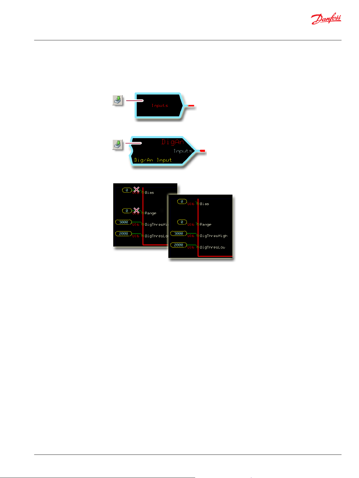
Configure the DigAn
Learn how to configure DigAn to receive input from the function block.
1. In the GUIDE template, enter the Inputs page.
2. Enter the page that receives the input.
3. Make the changes that are shown in the following figure.
18 | © Danfoss | March 2018 11062069 | AQ00000100en-US0401
Page 19
User Manual
PLUS+1® Compliant MBS 1250 Pressure Sensor Function Blocks
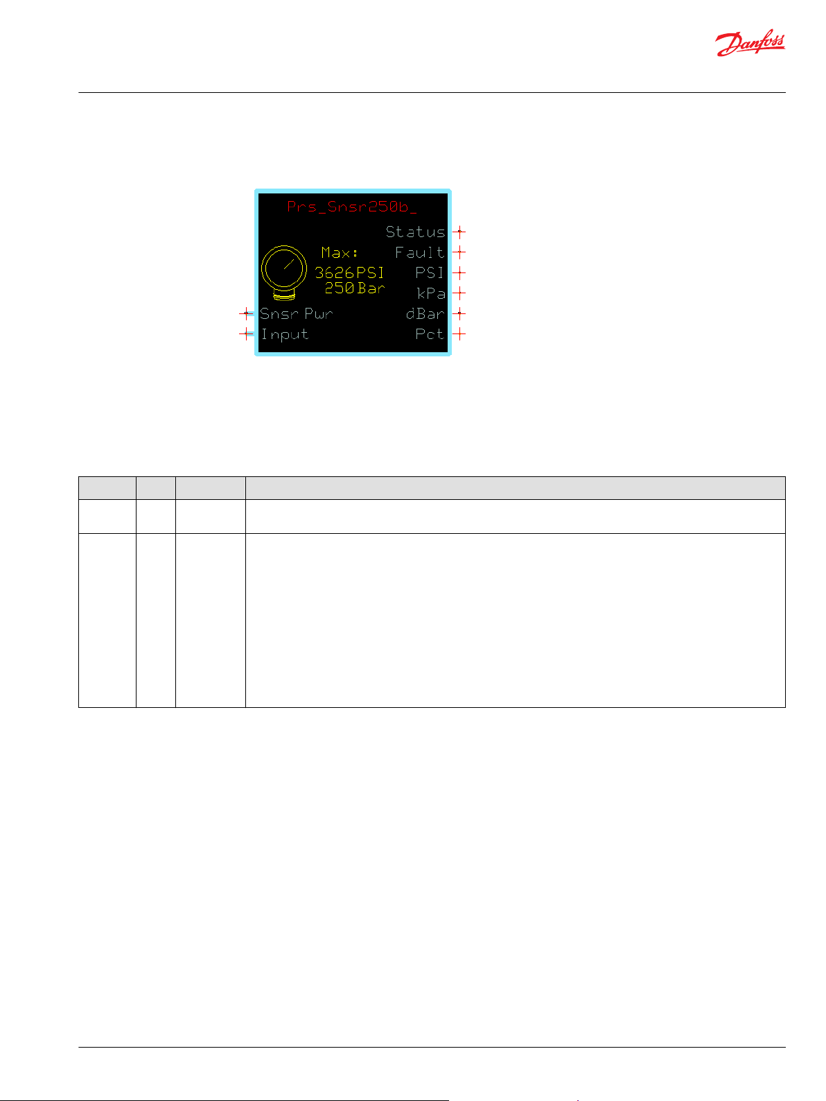
Prs_Snsr250b Function Block
This function block configures the output of MBS 1250 pressure sensors with a nominal 0–250 bar [25000
kPa/3626 PSI] range.
Inputs
Learn how the function block uses a reference voltage and a changing input voltage to produce PSI, Kpa,
dBar and Pct outputs.
Function Block Inputs
Input Type Range Description
Snsr Pwr —— 0–5250 mV Inputs a reference voltage that the PLUS+1 controller also applies to the Pin 1 (+ Supply) on the Pressure
Transmitter.
Input —— 0–5250 mV The function block compares the changing Input voltage with the constant Snsr Pwr reference voltage to produce
PSI, kPa, dBar , and Pct outputs.
The function block’s nominal operating range is between 10.00% and 90.00% of Snsr Pwr voltage.
When the Input voltage reaches:
•
10.00% of the Snsr Pwr voltage, the function block’s output starts rising above zero.
•
90.00% of the Snsr Pwr voltage, the function block outputs its maximum nominal outputs of 3626 PSI/25000
kPa/10000 (100.00%).
•
100.00% of the Snsr Pwr voltage, the function block outputs its maximum over-pressure outputs of 4080 PSI/
28125 kPa/11250 (112.50%).
The maximum over-pressure output equals 112.50% of the maximum nominal output. (25000 kPa x 112.50% =
28125 kPa)
©
Danfoss | March 2018 11062069 | AQ00000100en-US0401 | 19
Page 20
User Manual
PLUS+1® Compliant MBS 1250 Pressure Sensor Function Blocks
Prs_Snsr250b Function Block
Outputs
Learn about the outputs of the Prs_Snsr250b function block.
Function Block Outputs
Output Type Range Description
Status U16 —— Indicates if the Flt Pct value is within range or is set too high.
The Flt Pct sets the percentage that the Input voltage can rise above or fall below the function block’s operating
range without setting a fault condition.
You can change the Flt Pct value (1000 = 10.00%) on the inner page of the Prs_Snsr function block.
The Status output uses the bitwise scheme.
•
0x0000 = Block is OK.
•
0x8008 = Flt Pct value is too high.
Fault U16 —— Indicates if the voltage on the function block’s Input pin is too low or too high.
The Flt Pct sets the percentage that the Input voltage can rise above or fall below the function block’s operating
range without setting a fault condition.
You can change the Flt Pct value (1000 = 10.00%) on the inner page of the Prs_Snsr function block.
The Fault output uses the bitwise scheme.
•
0x0000 = Block is OK.
•
0x8001 = Input value is too low.
•
0x8002 = Input value is too high.
PSI U16 0–4080 Indicates pressure in pounds per square inch (PSI).
1 = 1 PSI.
kPa U16 0–28125 Indicates pressure in kilopascals (kPa).
1 = 1 kPa.
dBar U16 0–2812
Pct U16 0–11250 Indicates pressure as a percent of the function block’s operating range.
Indicates pressure in decibars (dBar).
1 = 1 dBar.
10000 = 100.00%.
Status and Fault Logic
This topic describes how status logic and fault logic are indicated for the function block.
Status Logic
The status code indicates the calibration state of the function block.
Status logic
Condition Hex
Invalid setup. 0x8008 1000 Flt Pct > 1000 (10.00%). Output = 0. Reduce Flt Pct.
*
Bit 16 set to 1 identifies a standard Danfoss status or fault code.
*
Binary Cause Response Correction
20 | © Danfoss | March 2018 11062069 | AQ00000100en-US0401
Page 21

User Manual
PLUS+1® Compliant MBS 1250 Pressure Sensor Function Blocks
Prs_Snsr250b Function Block
Fault Logic
Learn how fault logic can indicate problems, causes of problems, and solutions.
Fault logic
Condition Hex
Input value is too low. 0x8001 0001
Input value is too high. 0x8002 0010
*
Bit 16 set to 1 identifies a standard Danfoss status or fault code.
*
Binary Cause Response Correction
Volt(age) is less than [10% of
Snsr Pwr] - [Flt Pct of nominal
signal range (which is 80% of
Snsr Pwr)].
Snsr Pwr less than 0. Ensure correct software input is
Volt(age) is greater than [90% of
Snsr Pwr] + [Flt Pct of nominal
signal range (which is 80% of
Snsr Pwr)].
Snsr Pwr greater than 5250.
Output = 0.
Output is extrapolated beyond
the maximum value up to 11250
(112.50%).
Output = 0.
Inspect for open circuit in wire
connections to sensor.
made in the application.
Inspect for short circuit in wire
•
connections to sensor.
Verify the correct pressure
•
sensor is used for the
application.
Ensure correct software input is
made in the application.
Relationship Between Function Block Input and Output Signals
Use the plot to find out the relationships between the function block's Input voltages and its kPa and Pct
outputs.
This function block’s:
Flt Pct value = 500 (5.00%) and its Snsr Pwr value = 5000 mV.
•
Nominal Input voltage ranges between 10.00% (500 mV) and 90.00% (4500 mV) of the Snsr Pwr
•
voltage.
Nominal pressure output ranges between zero with the Input voltage at 500 mV and a maximum
•
nominal 25000 kPa/100.00% with the Input voltage at 4500 mV.
Maximum over-pressure output = 28125 kPa with the Input voltage at 5000 mV. (25000 maximum
•
nominal pressure x 112.50% = 28125 kPa maximum over-pressure)
When the Input voltage:
©
Danfoss | March 2018 11062069 | AQ00000100en-US0401 | 21
Page 22

User Manual
PLUS+1® Compliant MBS 1250 Pressure Sensor Function Blocks
Prs_Snsr250b Function Block
•
Drops below 300 mV, the function block outputs an input too low fault. (500 mV – 5% of the 4000 mV
nominal input voltage range = fault at 300 mV)
•
Rises above 4700 mV, the function block outputs an input too high fault. (4500 mV + 5% of the 4000
mV nominal input voltage range = fault at 4700 mV)
Function Block Connections
Connections you can make with the function block are described.
Function block connections
Item Description
1 Sensor voltage (varies with pressure).
2 Sensor reference power voltage.
3 Function block status.
4 Function block faults.
5 Pressure in PSI.
6 Pressure in kPa.
7 Pressure in decibar (dBar)
8 Pressure in % of range.
MC Controller—Input Configuration
Configure MFIn and DigAn to accept the input of the function block.
For MC Controllers, you route the function block’s Input through an MFIn or a DigAn.
You must change the MFIn and DigAn default configurations to accept this input.
22 | © Danfoss | March 2018 11062069 | AQ00000100en-US0401
Page 23

User Manual
PLUS+1® Compliant MBS 1250 Pressure Sensor Function Blocks
Prs_Snsr250b Function Block
Configure the MFIn
Learn how to configure MFIn to accept input from the function block.
1. In the GUIDE template, enter the Inputs page.
2. Enter the MFIn that receives the input.
3. Make the changes that are shown in this figure.
Configure the DigAn
Learn how to configure DigAn to accept input.
1. In the GUIDE template, enter the Inputs page.
2. Enter the page that receives the input.
©
Danfoss | March 2018 11062069 | AQ00000100en-US0401 | 23
Page 24

User Manual
PLUS+1® Compliant MBS 1250 Pressure Sensor Function Blocks
Prs_Snsr250b Function Block
3. Make the changes that are shown in the following figure.
SC Controller—Input Configuration
Configure MFIn and DigAn to accept the input of the function block.
You route the function block’s Input through an MFIn or a DigAn. You must change the MFIn and
DigAn default configurations to accept this input.
Configure the MFIn
Learn how to configure MFIn to accept input from the function block.
1. In the GUIDE template, enter the Inputs page.
2. Enter the page that receives the input.
3. Make the changes that are shown in the following figure.
24 | © Danfoss | March 2018 11062069 | AQ00000100en-US0401
Page 25

User Manual
PLUS+1® Compliant MBS 1250 Pressure Sensor Function Blocks
Prs_Snsr250b Function Block
Configure the DigAn
Learn how to configure DigAn to receive input from the function block.
1. In the GUIDE template, enter the Inputs page.
2. Enter the page that receives the input.
3. Make the changes that are shown in the following figure.
©
Danfoss | March 2018 11062069 | AQ00000100en-US0401 | 25
Page 26

User Manual
PLUS+1® Compliant MBS 1250 Pressure Sensor Function Blocks
Prs_Snsr400b Function Block
This function block configures the output of MBS 1250 pressure sensors with a nominal 0–400 bar [40000
kPa/5800 PSI] range.
Inputs
Learn how the function block uses a reference voltage and a changing input voltage to produce PSI, kPa,
dBar and Pct outputs.
Function Block Inputs
Input Type Range Description
Snsr Pwr —— 0–5250 mV Inputs a reference voltage that the PLUS+1 controller also applies to the Pin 1 (+ Supply) on the Pressure
Transmitter.
Input —— 0–5250 mV The function block compares the changing Input voltage with the constant Snsr Pwr reference voltage to produce
PSI, kPa, dBar , and Pct outputs.
The function block’s nominal operating range is between 10.00% and 90.00% of Snsr Pwr voltage.
When the Input voltage reaches:
•
10.00% of the Snsr Pwr voltage, the function block’s output starts rising above zero.
•
90.00% of the Snsr Pwr voltage, the function block outputs its maximum nominal outputs of 5800 PSI/40000
kPa/10000 (100.00%).
•
100.00% of the Snsr Pwr voltage, the function block outputs its maximum over-pressure outputs of 6525 PSI/
45000 kPa/11250 (112.50%).
The maximum over-pressure output equals 112.50% of the maximum nominal output. (40000 kPa x 112.50% =
45000 kPa)
26 | © Danfoss | March 2018 11062069 | AQ00000100en-US0401
Page 27

User Manual
PLUS+1® Compliant MBS 1250 Pressure Sensor Function Blocks
Prs_Snsr400b Function Block
Outputs
Learn about the outputs of the Prs_Snsr400b function block.
Function Block Outputs
Output Type Range Description
Status U16 —— Indicates if the Flt Pct value is within range or is set too high.
The Flt Pct sets the percentage that the Input voltage can rise above or fall below the function block’s operating
range without setting a fault condition.
You can change the Flt Pct value (1000 = 10.00%) on the inner page of the Prs_Snsr function block.
The Status output uses the bitwise scheme.
•
0x0000 = Block is OK.
•
0x8008 = Flt Pct value is too high.
Fault U16 —— Indicates if the voltage on the function block’s Input pin is too low or too high.
The Flt Pct sets the percentage that the Input voltage can rise above or fall below the function block’s operating
range without setting a fault condition.
You can change the Flt Pct value (1000 = 10.00%) on the inner page of the Prs_Snsr function block.
The Fault output uses the bitwise scheme.
•
0x0000 = Block is OK.
•
0x8001 = Input value is too low.
•
0x8002 = Input value is too high.
PSI U16 0–6525 Indicates pressure in pounds per square inch (PSI).
1 = 1 PSI.
kPa U16 0–45000 Indicates pressure in kilopascals (kPa).
1 = 1 kPa.
dBar U16 0–4500
Pct U16 0–111250 Indicates pressure as a percent of the function block’s operating range.
Indicates pressure in decibars (dBar).
1 = 1 dBar.
10000 = 100.00%.
Status and Fault Logic
This topic describes how status logic and fault logic are indicated for the function block.
Status Logic
The status code indicates the calibration state of the function block.
Status logic
Condition Hex
Invalid setup. 0x8008 1000 Flt Pct > 1000 (10.00%). Output = 0. Reduce Flt Pct.
*
Bit 16 set to 1 identifies a standard Danfoss status or fault code.
*
Binary Cause Response Correction
©
Danfoss | March 2018 11062069 | AQ00000100en-US0401 | 27
Page 28

User Manual
PLUS+1® Compliant MBS 1250 Pressure Sensor Function Blocks
Prs_Snsr400b Function Block
Fault Logic
Learn how fault logic can indicate problems, causes of problems, and solutions.
Fault logic
Condition Hex
Input value is too low. 0x8001 0001
Input value is too high. 0x8002 0010
*
Bit 16 set to 1 identifies a standard Danfoss status or fault code.
*
Binary Cause Response Correction
Volt(age) is less than [10% of
Snsr Pwr] - [Flt Pct of nominal
signal range (which is 80% of
Snsr Pwr)].
Snsr Pwr less than 0. Ensure correct software input is
Volt(age) is greater than [90% of
Snsr Pwr] + [Flt Pct of nominal
signal range (which is 80% of
Snsr Pwr)].
Snsr Pwr greater than 5250.
Output = 0.
Output is extrapolated beyond
the maximum value up to 11250
(112.50%).
Output = 0.
Inspect for open circuit in wire
connections to sensor.
made in the application.
Inspect for short circuit in wire
•
connections to sensor.
Verify the correct pressure
•
sensor is used for the
application.
Ensure correct software input is
made in the application.
Relationship Between Function Block Input and Output Signals
Use the plot to find out the relationships between the function block's Input voltages and its kPa and Pct
outputs.
This function block’s:
Flt Pct value = 500 (5.00%) and its Snsr Pwr value = 5000 mV.
•
Nominal Input voltage ranges between 10.00% (500 mV) and 90.00% (4500 mV) of the Snsr Pwr
•
voltage.
Nominal pressure output ranges between zero with the Input voltage at 500 mV and a maximum
•
nominal 40000 kPa/100.00% with the Input voltage at 4500 mV.
Maximum over-pressure output = 45000 kPa with the Input voltage at 5000 mV.
•
(40000 maximum nominal pressure x 112.50% = 45000 kPa maximum over-pressure)
When the Input voltage:
28 | © Danfoss | March 2018 11062069 | AQ00000100en-US0401
Page 29

User Manual
PLUS+1® Compliant MBS 1250 Pressure Sensor Function Blocks
Prs_Snsr400b Function Block
Drops below 300 mV, the function block outputs an input too low fault.
•
(500 mV – 5% of the 4000 mV nominal input voltage range = fault at 300 mV)
Rises above 4700 mV, the function block outputs an input too high fault.
•
(4500 mV + 5% of the 4000 mV nominal input voltage range = fault at 4700 mV)
Function Block Connections
Connections you can make with the function block are described.
Function block connections
Item Description
1 Sensor voltage (varies with pressure).
2 Sensor reference power voltage.
3 Function block status.
4 Function block faults.
5 Pressure in PSI.
6 Pressure in kPa.
7 Pressure in decibar (dBar)
8 Pressure in % of range.
MC Controller—Input Configuration
Configure MFIn and DigAn to accept the input of the function block.
For MC Controllers, you route the function block’s Input through an MFIn or a DigAn.
You must change the MFIn and DigAn default configurations to accept this input.
©
Danfoss | March 2018 11062069 | AQ00000100en-US0401 | 29
Page 30

User Manual
PLUS+1® Compliant MBS 1250 Pressure Sensor Function Blocks
Prs_Snsr400b Function Block
Configure the MFIn
Learn how to configure MFIn to accept input from the function block.
1. In the GUIDE template, enter the Inputs page.
2. Enter the MFIn that receives the input.
3. Make the changes that are shown in this figure.
Configure the DigAn
Learn how to configure DigAn to accept input.
1. In the GUIDE template, enter the Inputs page.
2. Enter the page that receives the input.
30 | © Danfoss | March 2018 11062069 | AQ00000100en-US0401
Page 31

User Manual
PLUS+1® Compliant MBS 1250 Pressure Sensor Function Blocks
Prs_Snsr400b Function Block
3. Make the changes that are shown in the following figure.
SC Controller—Input Configuration
Configure MFIn and DigAn to accept the input of the function block.
You route the function block’s Input through an MFIn or a DigAn. You must change the MFIn and
DigAn default configurations to accept this input.
Configure the MFIn
Learn how to configure MFIn to accept input from the function block.
1. In the GUIDE template, enter the Inputs page.
2. Enter the page that receives the input.
3. Make the changes that are shown in the following figure.
©
Danfoss | March 2018 11062069 | AQ00000100en-US0401 | 31
Page 32

User Manual
PLUS+1® Compliant MBS 1250 Pressure Sensor Function Blocks
Prs_Snsr400b Function Block
Configure the DigAn
Learn how to configure DigAn to receive input from the function block.
1. In the GUIDE template, enter the Inputs page.
2. Enter the page that receives the input.
3. Make the changes that are shown in the following figure.
32 | © Danfoss | March 2018 11062069 | AQ00000100en-US0401
Page 33

User Manual
PLUS+1® Compliant MBS 1250 Pressure Sensor Function Blocks
Prs_Snsr500b Function Block
This function block configures the output of MBS 1250 pressure sensors with a nominal 0–500 bar [50000
kPa/7250 PSI] range.
Inputs
Learn how the function block uses a reference voltage and a changing input voltage to produce PSI, kPa,
dBar and Pct outputs.
Function Block Inputs
Input Type Range Description
Snsr Pwr —— 0–5250 mV Inputs a reference voltage that the PLUS+1® controller also applies to the Pin 1 (+ Supply) on the pressure
transmitter.
Input —— 0–5250 mV The function block compares the changing Input voltage with the constant Snsr Pwr reference voltage to produce
PSI, kPa, dBar and Pct outputs.
The function block’s nominal operating range is between 10.00% and 90.00% of Snsr Pwr voltage.
When the Input voltage reaches:
•
10.00% of the Snsr Pwr voltage, the function block’s output starts rising above zero.
•
90.00% of the Snsr Pwr voltage, the function block outputs its maximum nominal outputs of 7250 PSI/50000 kPa/
10000 (100.00%).
•
100.00% of the Snsr Pwr voltage, the function block outputs its maximum over-pressure outputs of 8156 PSI/
56250 kPa/11250 (112.50%).
The maximum over-pressure output equals 112.50% of the maximum nominal output. (50000 kPa x 112.50% =
56250 kPa)
©
Danfoss | March 2018 11062069 | AQ00000100en-US0401 | 33
Page 34

User Manual
PLUS+1® Compliant MBS 1250 Pressure Sensor Function Blocks
Prs_Snsr500b Function Block
Outputs
Learn about the outputs of the Prs_Snsr500b function block.
Function Block Outputs
Output Type Range Description
Status U16 —— Indicates if the Flt Pct value is within range or is set too high.
The Flt Pct sets the percentage that the Input voltage can rise above or fall below the function block’s operating range
without setting a fault condition.
You can change the Flt Pct value (1000 = 10.00%) on the inner page of the Prs_Snsr function block.
The Status output uses the bitwise scheme.
•
0x0000 = Block is OK.
•
0x8008 = Flt Pct value is too high.
Fault U16 —— Indicates if the voltage on the function block’s Input pin is too low or too high.
The Flt Pct sets the percentage that the Input voltage can rise above or fall below the function block’s operating range
without setting a fault condition.
You can change the Flt Pct value (1000 = 10.00%) on the inner page of the Prs_Snsr function block.
The Fault output uses the bitwise scheme.
•
0x0000 = Block is OK.
•
0x8001 = Input value is too low.
•
0x8002 = Input value is too high.
PSI U16 0–8156 Indicates pressure in pounds per square inch (PSI).
1 = 1 PSI.
kPa U16 0–56250 Indicates pressure in kilopascals (kPa).
1 = 1 kPa.
dBar U16 0–5625
Pct U16 0–11250 Indicates pressure as a percent of the function block’s operating range.
Indicates pressure in decibars (dBar).
1 = 1 dBar.
10000 = 100.00%.
Status and Fault Logic
This topic describes how status logic and fault logic are indicated for the function block.
Status Logic
The status code indicates the calibration state of the function block.
Status logic
Condition Hex
Invalid setup. 0x8008 1000 Flt Pct > 1000 (10.00%). Output = 0. Reduce Flt Pct.
*
Bit 16 set to 1 identifies a standard Danfoss status or fault code.
*
Binary Cause Response Correction
34 | © Danfoss | March 2018 11062069 | AQ00000100en-US0401
Page 35

User Manual
PLUS+1® Compliant MBS 1250 Pressure Sensor Function Blocks
Prs_Snsr500b Function Block
Fault Logic
Learn how fault logic can indicate problems, causes of problems, and solutions.
Fault logic
Condition Hex
Input value is too low. 0x8001 0001
Input value is too high. 0x8002 0010
*
Bit 16 set to 1 identifies a standard Danfoss status or fault code.
*
Binary Cause Response Correction
Volt(age) is less than [10% of
Snsr Pwr] - [Flt Pct of nominal
signal range (which is 80% of
Snsr Pwr)].
Snsr Pwr less than 0. Ensure correct software input is
Volt(age) is greater than [90% of
Snsr Pwr] + [Flt Pct of nominal
signal range (which is 80% of
Snsr Pwr)].
Snsr Pwr greater than 5250.
Output = 0.
Output is extrapolated beyond
the maximum value up to 11250
(112.50%).
Output = 0.
Inspect for open circuit in wire
connections to sensor.
made in the application.
Inspect for short circuit in wire
•
connections to sensor.
Verify the correct pressure
•
sensor is used for the
application.
Ensure correct software input is
made in the application.
Relationship Between Function Block Input and Output Signals
Use the plot to find out the relationships between the function block's Input voltages and its kPa and Pct
outputs.
This function block’s:
Flt Pct value = 500 (5.00%) and its Snsr Pwr value = 5000 mV.
•
Nominal Input voltage ranges between 10.00% (500 mV) and 90.00% (4500 mV) of the Snsr Pwr
•
voltage.
Nominal pressure output ranges between zero with the Input voltage at 500 mV and a maximum
•
nominal 50000 kPa/100.00% with the Input voltage at 4500 mV.
Maximum over-pressure output = 56250 kPa with the Input voltage at 5000 mV. (50000 maximum
•
nominal pressure x 112.50% = 56250 kPa maximum over-pressure)
When the Input voltage:
©
Danfoss | March 2018 11062069 | AQ00000100en-US0401 | 35
Page 36

User Manual
PLUS+1® Compliant MBS 1250 Pressure Sensor Function Blocks
Prs_Snsr500b Function Block
Drops below 300 mV, the function block outputs an input too low fault.
•
(500 mV – 5% of the 4000 mV nominal input voltage range = fault at 300 mV)
Rises above 4700 mV, the function block outputs an input too high fault.
•
(4500 mV + 5% of the 4000 mV nominal input voltage range = fault at 4700 mV)
Function Block Connections
Connections you can make with the function block are described.
Function block connections
Item Description
1 Sensor voltage (varies with pressure).
2 Sensor reference power voltage.
3 Function block status.
4 Function block faults.
5 Pressure in PSI.
6 Pressure in kPa.
7 Pressure in decibar (dBar)
8 Pressure in % of range.
MC Controller—Input Configuration
Configure MFIn and DigAn to accept the input of the function block.
For MC Controllers, you route the function block’s Input through an MFIn or a DigAn.
You must change the MFIn and DigAn default configurations to accept this input.
36 | © Danfoss | March 2018 11062069 | AQ00000100en-US0401
Page 37

User Manual
PLUS+1® Compliant MBS 1250 Pressure Sensor Function Blocks
Prs_Snsr500b Function Block
Configure the MFIn
Learn how to configure MFIn to accept input from the function block.
1. In the GUIDE template, enter the Inputs page.
2. Enter the MFIn that receives the input.
3. Make the changes that are shown in this figure.
Configure the DigAn
Learn how to configure DigAn to accept input.
1. In the GUIDE template, enter the Inputs page.
2. Enter the page that receives the input.
©
Danfoss | March 2018 11062069 | AQ00000100en-US0401 | 37
Page 38

User Manual
PLUS+1® Compliant MBS 1250 Pressure Sensor Function Blocks
Prs_Snsr500b Function Block
3. Make the changes that are shown in the following figure.
SC Controller—Input Configuration
Configure MFIn and DigAn to accept the input of the function block.
You route the function block’s Input through an MFIn or a DigAn. You must change the MFIn and
DigAn default configurations to accept this input.
Configure the MFIn
Learn how to configure MFIn to accept input from the function block.
1. In the GUIDE template, enter the Inputs page.
2. Enter the page that receives the input.
3. Make the changes that are shown in the following figure.
38 | © Danfoss | March 2018 11062069 | AQ00000100en-US0401
Page 39

User Manual
PLUS+1® Compliant MBS 1250 Pressure Sensor Function Blocks
Prs_Snsr500b Function Block
Configure the DigAn
Learn how to configure DigAn to receive input from the function block.
1. In the GUIDE template, enter the Inputs page.
2. Enter the page that receives the input.
3. Make the changes that are shown in the following figure.
©
Danfoss | March 2018 11062069 | AQ00000100en-US0401 | 39
Page 40

User Manual
PLUS+1® Compliant MBS 1250 Pressure Sensor Function Blocks
Prs_Snsr550b Function Block
This function block configures the output of MBS 1250 pressure sensors with a nominal 0–550 bar [55000
kPa/7977 PSI] range.
Inputs
Learn how the function block uses a reference voltage and a changing input voltage to produce PSI, kPa,
dBar and Pct outputs.
Function Block Inputs
Input Type Range Description
Snsr Pwr —— 0–5250 mV Inputs a reference voltage that the PLUS+1® controller also applies to the Pin 1 (+ Supply) on the pressure
transmitter.
Input —— 0–5250 mV The function block compares the changing Input voltage with the constant Snsr Pwr reference voltage to produce
PSI, kPa, dBar and Pct outputs.
The function block’s nominal operating range is between 10.00% and 90.00% of Snsr Pwr voltage.
When the Input voltage reaches:
•
10.00% of the Snsr Pwr voltage, the function block’s output starts rising above zero.
•
90.00% of the Snsr Pwr voltage, the function block outputs its maximum nominal outputs of 7250 PSI/50000 kPa/
10000 (100.00%).
•
100.00% of the Snsr Pwr voltage, the function block outputs its maximum over-pressure outputs of 8156 PSI/
56250 kPa/11250 (112.50%).
The maximum over-pressure output equals 112.50% of the maximum nominal output. (50000 kPa x 112.50% =
56250 kPa)
40 | © Danfoss | March 2018 11062069 | AQ00000100en-US0401
Page 41

User Manual
PLUS+1® Compliant MBS 1250 Pressure Sensor Function Blocks
Prs_Snsr550b Function Block
Outputs
Learn about the outputs of the Prs_Snsr550b function block.
Function Block Outputs
Output Type Range Description
Status U16 —— Indicates if the Flt Pct value is within range or is set too high.
The Flt Pct sets the percentage that the Input voltage can rise above or fall below the function block’s operating range
without setting a fault condition.
You can change the Flt Pct value (1000 = 10.00%) on the inner page of the Prs_Snsr function block.
The Status output uses the bitwise scheme.
•
0x0000 = Block is OK.
•
0x8008 = Flt Pct value is too high.
Fault U16 —— Indicates if the voltage on the function block’s Input pin is too low or too high.
The Flt Pct sets the percentage that the Input voltage can rise above or fall below the function block’s operating range
without setting a fault condition.
You can change the Flt Pct value (1000 = 10.00%) on the inner page of the Prs_Snsr function block.
The Fault output uses the bitwise scheme.
•
0x0000 = Block is OK.
•
0x8001 = Input value is too low.
•
0x8002 = Input value is too high.
PSI U16 0–8156 Indicates pressure in pounds per square inch (PSI).
1 = 1 PSI.
kPa U16 0–56250 Indicates pressure in kilopascals (kPa).
1 = 1 kPa.
dBar U16 0–5625
Pct U16 0–11250 Indicates pressure as a percent of the function block’s operating range.
Indicates pressure in decibars (dBar).
1 = 1 dBar.
10000 = 100.00%.
Status and Fault Logic
This topic describes how status logic and fault logic are indicated for the function block.
Status Logic
The status code indicates the calibration state of the function block.
Status logic
Condition Hex
Invalid setup. 0x8008 1000 Flt Pct > 1000 (10.00%). Output = 0. Reduce Flt Pct.
*
Bit 16 set to 1 identifies a standard Danfoss status or fault code.
*
Binary Cause Response Correction
©
Danfoss | March 2018 11062069 | AQ00000100en-US0401 | 41
Page 42

User Manual
PLUS+1® Compliant MBS 1250 Pressure Sensor Function Blocks
Prs_Snsr550b Function Block
Fault Logic
Learn how fault logic can indicate problems, causes of problems, and solutions.
Fault logic
Condition Hex
Input value is too low. 0x8001 0001
Input value is too high. 0x8002 0010
*
Bit 16 set to 1 identifies a standard Danfoss status or fault code.
*
Binary Cause Response Correction
Volt(age) is less than [10% of
Snsr Pwr] - [Flt Pct of nominal
signal range (which is 80% of
Snsr Pwr)].
Snsr Pwr less than 0. Ensure correct software input is
Volt(age) is greater than [90% of
Snsr Pwr] + [Flt Pct of nominal
signal range (which is 80% of
Snsr Pwr)].
Snsr Pwr greater than 5250.
Output = 0.
Output is extrapolated beyond
the maximum value up to 11250
(112.50%).
Output = 0.
Inspect for open circuit in wire
connections to sensor.
made in the application.
Inspect for short circuit in wire
•
connections to sensor.
Verify the correct pressure
•
sensor is used for the
application.
Ensure correct software input is
made in the application.
Relationship Between Function Block Input and Output Signals
Use the plot to find out the relationships between the function block's Input voltages and its kPa and Pct
outputs.
This function block’s:
42 | © Danfoss | March 2018 11062069 | AQ00000100en-US0401
Page 43

User Manual
PLUS+1® Compliant MBS 1250 Pressure Sensor Function Blocks
Prs_Snsr550b Function Block
Flt Pct value = 500 (5.00%) and its Snsr Pwr value = 5000 mV.
•
Nominal Input voltage ranges between 10.00% (500 mV) and 90.00% (4500 mV) of the Snsr Pwr
•
voltage.
Nominal pressure output ranges between zero with the Input voltage at 500 mV and a maximum
•
nominal 50000 kPa/100.00% with the Input voltage at 4500 mV.
Maximum over-pressure output = 50000 kPa with the Input voltage at 5000 mV. (61875 maximum
•
nominal pressure x 112.50% = 18000 kPa maximum over-pressure)
When the Input voltage:
Drops below 300 mV, the function block outputs an input too low fault. (500 mV – 5% of the 4000 mV
•
nominal input voltage range = fault at 300 mV)
Rises above 4700 mV, the function block outputs an input too high fault. (4500 mV + 5% of the 4000
•
mV nominal input voltage range = fault at 4700 mV)
Function Block Connections
Connections you can make with the function block are described.
Function block connections
Item Description
1 Sensor voltage (varies with pressure).
2 Sensor reference power voltage.
3 Function block status.
4 Function block faults.
5 Pressure in PSI.
6 Pressure in kPa.
7 Pressure in decibar (dBar)
8 Pressure in % of range.
MC Controller—Input Configuration
Configure MFIn and DigAn to accept the input of the function block.
For MC Controllers, you route the function block’s Input through an MFIn or a DigAn.
You must change the MFIn and DigAn default configurations to accept this input.
©
Danfoss | March 2018 11062069 | AQ00000100en-US0401 | 43
Page 44

User Manual
PLUS+1® Compliant MBS 1250 Pressure Sensor Function Blocks
Prs_Snsr550b Function Block
Configure the MFIn
Learn how to configure MFIn to accept input from the function block.
1. In the GUIDE template, enter the Inputs page.
2. Enter the MFIn that receives the input.
3. Make the changes that are shown in this figure.
Configure the DigAn
Learn how to configure DigAn to accept input.
1. In the GUIDE template, enter the Inputs page.
2. Enter the page that receives the input.
44 | © Danfoss | March 2018 11062069 | AQ00000100en-US0401
Page 45

User Manual
PLUS+1® Compliant MBS 1250 Pressure Sensor Function Blocks
Prs_Snsr550b Function Block
3. Make the changes that are shown in the following figure.
SC Controller—Input Configuration
Configure MFIn and DigAn to accept the input of the function block.
You route the function block’s Input through an MFIn or a DigAn. You must change the MFIn and
DigAn default configurations to accept this input.
Configure the MFIn
Learn how to configure MFIn to accept input from the function block.
1. In the GUIDE template, enter the Inputs page.
2. Enter the page that receives the input.
3. Make the changes that are shown in the following figure.
©
Danfoss | March 2018 11062069 | AQ00000100en-US0401 | 45
Page 46

User Manual
PLUS+1® Compliant MBS 1250 Pressure Sensor Function Blocks
Prs_Snsr550b Function Block
Configure the DigAn
Learn how to configure DigAn to receive input from the function block.
1. In the GUIDE template, enter the Inputs page.
2. Enter the page that receives the input.
3. Make the changes that are shown in the following figure.
46 | © Danfoss | March 2018 11062069 | AQ00000100en-US0401
Page 47

User Manual
PLUS+1® Compliant MBS 1250 Pressure Sensor Function Blocks
Prs_Snsr600b Function Block
This function block configures the output of MBS 1250 pressure sensors with a nominal 0–600 bar [60000
kPa/8700 PSI] range.
Inputs
Learn how the function block uses a reference voltage and a changing input voltage to produce PSI, kPa,
dBar and Pct outputs.
Function Block Inputs
Input Type Range Description
Snsr Pwr —— 0–5250 mV Inputs a reference voltage that the PLUS+1 controller also applies to the Pin 1 (+ Supply) on the Pressure
Transmitter.
Input —— 0–5250 mV The function block compares the changing Input voltage with the constant Snsr Pwr reference voltage to produce
PSI, kPa, dBar, and Pct outputs.
The function block’s nominal operating range is between 10.00% and 90.00% of Snsr Pwr voltage.
When the Input voltage reaches:
•
10.00% of the Snsr Pwr voltage, the function block’s output starts rising above zero.
•
90.00% of the Snsr Pwr voltage, the function block outputs its maximum nominal outputs of 8700 PSI/60000
kPa/10000 (100.00%).
•
100.00% of the Snsr Pwr voltage, the function block outputs its maximum over-pressure outputs of 9788 PSI/
67500 kPa/11250 (112.50%).
The maximum over-pressure output equals 112.50% of the maximum nominal output. (8700 PSI x 112.50% =
9788 PSI)
©
Danfoss | March 2018 11062069 | AQ00000100en-US0401 | 47
Page 48

User Manual
PLUS+1® Compliant MBS 1250 Pressure Sensor Function Blocks
Prs_Snsr600b Function Block
Outputs
Learn about the outputs of the Prs_Snsr600b function block.
Function Block Outputs
Output Type Range Description
Status U16 —— Indicates if the Flt Pct value is within range or is set too high.
The Flt Pct sets the percentage that the Input voltage can rise above or fall below the function block’s operating range
without setting a fault condition.
You can change the Flt Pct value (1000 = 10.00%) on the inner page of the Prs_Snsr function block.
The Status output uses the bitwise scheme.
•
0x0000 = Block is OK.
•
0x8008 = Flt Pct value is too high.
Fault U16 —— Indicates if the voltage on the function block’s Input pin is too low or too high.
The Flt Pct sets the percentage that the Input voltage can rise above or fall below the function block’s operating range
without setting a fault condition.
You can change the Flt Pct value (1000 = 10.00%) on the inner page of the Prs_Snsr function block.
The Fault output uses the bitwise scheme.
•
0x0000 = Block is OK.
•
0x8001 = Input value is too low.
•
0x8002 = Input value is too high.
PSI U16 0–9788 Indicates pressure in pounds per square inch (PSI).
1 = 1 PSI.
kPa U32 0–67500 Indicates pressure in kilopascals (kPa).
1 = 1 kPa.
dBar U16 0–6750
Pct U16 0–11250 Indicates pressure as a percent of the function block’s operating range.
Indicates pressure in decibars (dBar).
1 = 1 dBar.
10000 = 100.00%.
Status and Fault Logic
This topic describes how status logic and fault logic are indicated for the function block.
Status Logic
The status code indicates the calibration state of the function block.
Status logic
Condition Hex
Invalid setup. 0x8008 1000 Flt Pct > 1000 (10.00%). Output = 0. Reduce Flt Pct.
*
Bit 16 set to 1 identifies a standard Danfoss status or fault code.
*
Binary Cause Response Correction
48 | © Danfoss | March 2018 11062069 | AQ00000100en-US0401
Page 49

User Manual
PLUS+1® Compliant MBS 1250 Pressure Sensor Function Blocks
Prs_Snsr600b Function Block
Fault Logic
Learn how fault logic can indicate problems, causes of problems, and solutions.
Fault logic
Condition Hex
Input value is too low. 0x8001 0001
Input value is too high. 0x8002 0010
*
Bit 16 set to 1 identifies a standard Danfoss status or fault code.
*
Binary Cause Response Correction
Volt(age) is less than [10% of
Snsr Pwr] - [Flt Pct of nominal
signal range (which is 80% of
Snsr Pwr)].
Snsr Pwr less than 0. Ensure correct software input is
Volt(age) is greater than [90% of
Snsr Pwr] + [Flt Pct of nominal
signal range (which is 80% of
Snsr Pwr)].
Snsr Pwr greater than 5250.
Output = 0.
Output is extrapolated beyond
the maximum value up to 11250
(112.50%).
Output = 0.
Inspect for open circuit in wire
connections to sensor.
made in the application.
Inspect for short circuit in wire
•
connections to sensor.
Verify the correct pressure
•
sensor is used for the
application.
Ensure correct software input is
made in the application.
Relationship Between Function Block Input and Output Signals
Use the plot to find out the relationships between the function block's Input voltages and its kPa and Pct
outputs.
This function block’s:
Flt Pct value = 500 (5.00%) and its Snsr Pwr value = 5000 mV.
•
Nominal Input voltage ranges between 10.00% (500 mV) and 90.00% (4500 mV) of the Snsr Pwr
•
voltage.
Nominal pressure output ranges between zero with the Input voltage at 500 mV and a maximum
•
nominal 60000 kPa/100.00% with the Input voltage at 4500 mV.
Maximum over-pressure output = 65535 kPa with the Input voltage at 5000 mV.
•
(The U16 data type limits the kPa output to 65535; other outputs are not limited.)
When the Input voltage:
©
Danfoss | March 2018 11062069 | AQ00000100en-US0401 | 49
Page 50

User Manual
PLUS+1® Compliant MBS 1250 Pressure Sensor Function Blocks
Prs_Snsr600b Function Block
Drops below 300 mV, the function block outputs an input too low fault.
•
(500 mV – 5% of the 4000 mV nominal input voltage range = fault at 300 mV)
Rises above 4700 mV, the function block outputs an input too high fault.
•
(4500 mV + 5% of the 4000 mV nominal input voltage range = fault at 4700 mV)
Function Block Connections
Connections you can make with the function block are described.
Function block connections
Item Description
1 Sensor voltage (varies with pressure).
2 Sensor reference power voltage.
3 Function block status.
4 Function block faults.
5 Pressure in PSI.
6 Pressure in kPa.
7 Pressure in decibar (dBar)
8 Pressure in % of range.
MC Controller—Input Configuration
Configure MFIn and DigAn to accept the input of the function block.
For MC Controllers, you route the function block’s Input through an MFIn or a DigAn.
You must change the MFIn and DigAn default configurations to accept this input.
50 | © Danfoss | March 2018 11062069 | AQ00000100en-US0401
Page 51

User Manual
PLUS+1® Compliant MBS 1250 Pressure Sensor Function Blocks
Prs_Snsr600b Function Block
Configure the MFIn
Learn how to configure MFIn to accept input from the function block.
1. In the GUIDE template, enter the Inputs page.
2. Enter the MFIn that receives the input.
3. Make the changes that are shown in this figure.
Configure the DigAn
Learn how to configure DigAn to accept input.
1. In the GUIDE template, enter the Inputs page.
2. Enter the page that receives the input.
©
Danfoss | March 2018 11062069 | AQ00000100en-US0401 | 51
Page 52

User Manual
PLUS+1® Compliant MBS 1250 Pressure Sensor Function Blocks
Prs_Snsr600b Function Block
3. Make the changes that are shown in the following figure.
SC Controller—Input Configuration
Configure MFIn and DigAn to accept the input of the function block.
You route the function block’s Input through an MFIn or a DigAn. You must change the MFIn and
DigAn default configurations to accept this input.
Configure the MFIn
Learn how to configure MFIn to accept input from the function block.
1. In the GUIDE template, enter the Inputs page.
2. Enter the page that receives the input.
3. Make the changes that are shown in the following figure.
52 | © Danfoss | March 2018 11062069 | AQ00000100en-US0401
Page 53

User Manual
PLUS+1® Compliant MBS 1250 Pressure Sensor Function Blocks
Prs_Snsr600b Function Block
Configure the DigAn
Learn how to configure DigAn to receive input from the function block.
1. In the GUIDE template, enter the Inputs page.
2. Enter the page that receives the input.
3. Make the changes that are shown in the following figure.
©
Danfoss | March 2018 11062069 | AQ00000100en-US0401 | 53
Page 54

User Manual
PLUS+1® Compliant MBS 1250 Pressure Sensor Function Blocks
Prs_Snsr_Gen Function Block
This function block configures the output of MBS 1250 pressure sensors with a nominal bar range
specifed by a parameter to scale the output.
Inputs
Learn how the function block uses a parameter to customize the scaling values for output and how it
uses a reference voltage and a changing input voltage to produce PSI, kPa, dBar and Pct outputs.
Function Block Inputs
Input Type Range Description
Snsr Pwr U16 0–5250 mV Inputs a reference voltage that the PLUS+1® controller also applies to the Pin 1 (+ Supply) on the pressure
transmitter.
Input U16 0–5250 mV The function block compares the changing Input voltage with the constant Snsr Pwr reference voltage to produce
PSI, kPa, dBar and Pct outputs.
The function block’s nominal operating range is between 10.00% and 90.00% of Snsr Pwr voltage.
When the Input voltage reaches:
•
10.00% of the Snsr Pwr voltage, the function block’s output starts rising above zero.
•
90.00% of the Snsr Pwr voltage, the function block outputs its maximum nominal outputs of PSI and kPa. The
maximum nominal output is specified by Bar and is limited to 2200.
•
100.00% of the Snsr Pwr voltage, the function block outputs its maximum over-pressure outputs of PSI and kPa
at 112.50% of the output defined by Bar.
The maximum over-pressure output equals 112.50% of the maximum nominal output. The generic function
block allows you to specify the pressure range allowed.
Para-Bar
U16 User defined
range,
0-2200.
The function block uses Bar to rescale the output of the pressure sensor for OEM products. The output of the
function block is expressed in Bar, and has a range that can be defined from 0 to 2200.
Outputs
Learn how the outputs of the general function block work.
Function Block Outputs
Output Type Range Description
Status U16 —— Indicates if the Flt Pct value is within range or is set too high.
The Flt Pct sets the percentage that the Input voltage can rise above or fall below the function block’s operating range
without setting a fault condition.
You can change the Flt Pct value (1000 = 10.00%) on the inner page of the Prs_Snsr function block.
The Status output uses the bitwise scheme.
•
0x0000 = Block is OK.
•
0x8008 = Flt Pct value is too high.
54 | © Danfoss | March 2018 11062069 | AQ00000100en-US0401
Page 55

User Manual
PLUS+1® Compliant MBS 1250 Pressure Sensor Function Blocks
Prs_Snsr_Gen Function Block
Function Block Outputs (continued)
Fault U16 —— Indicates if the voltage on the function block’s Input pin is too low or too high.
The Flt Pct sets the percentage that the Input voltage can rise above or fall below the function block’s operating range
without setting a fault condition.
You can change the Flt Pct value (1000 = 10.00%) on the inner page of the Prs_Snsr function block.
The Fault output uses the bitwise scheme.
•
0x0000 = Block is OK.
•
0x8001 = Input value is too low.
•
0x8002 = Input value is too high.
PSI U16 0–35896 Indicates pressure in pounds per square inch (PSI).
1 = 1 PSI.
kPa U16 0–247500 Indicates pressure in kilopascals (kPa).
1 = 1 kPa.
dBar U16 0–24750
Pct U16 0–11250 Indicates pressure as a percent of the function block’s operating range.
Indicates pressure in decibars (dBar).
1 = 1 dBar.
10000 = 100.00%.
Status and Fault Logic
This topic describes how status logic and fault logic are indicated for the function block.
Status Logic
The status code indicates the calibration state of the function block.
Status logic
Condition Hex
Invalid setup. 0x8008 1000 Flt Pct > 1000 (10.00%). Output = 0. Reduce Flt Pct.
*
Bit 16 set to 1 identifies a standard Danfoss status or fault code.
*
Binary Cause Response Correction
Fault Logic
Learn how fault logic can indicate problems, causes of problems, and solutions.
Fault logic
Condition Hex
Input value is too low. 0x8001 0001
Input value is too high. 0x8002 0010
*
Bit 16 set to 1 identifies a standard Danfoss status or fault code.
*
Binary Cause Response Correction
Volt(age) is less than [10% of
Snsr Pwr] - [Flt Pct of nominal
signal range (which is 80% of
Snsr Pwr)].
Snsr Pwr less than 0. Ensure correct software input is
Volt(age) is greater than [90% of
Snsr Pwr] + [Flt Pct of nominal
signal range (which is 80% of
Snsr Pwr)].
Snsr Pwr greater than 5250.
Output = 0.
Output is extrapolated beyond
the maximum value up to 11250
(112.50%).
Output = 0.
Inspect for open circuit in wire
connections to sensor.
made in the application.
Inspect for short circuit in wire
•
connections to sensor.
Verify the correct pressure
•
sensor is used for the
application.
Ensure correct software input is
made in the application.
©
Danfoss | March 2018 11062069 | AQ00000100en-US0401 | 55
Page 56

User Manual
PLUS+1® Compliant MBS 1250 Pressure Sensor Function Blocks
Prs_Snsr_Gen Function Block
Relationship Between Function Block Input and Output Signals
Use the plot to find out the relationships between the function block's Input voltages and its kPa and Pct
outputs.
This function block’s:
Flt Pct value = 500 (5.00%) and its Snsr Pwr value = 5000 mV.
•
Nominal Input voltage ranges between 10.00% (500 mV) and 90.00% (4500 mV) of the Snsr Pwr
•
voltage.
Nominal pressure output ranges between zero with the Input voltage at 500 mV and a maximum
•
nominal 100.00% with the Input voltage at 4500 mV.
Maximum over-pressure output with the Input voltage at 5000 mV. (maximum nominal pressure x
•
112.50% = maximum over-pressure)
When the Input voltage:
•
Drops below 300 mV, the function block outputs an input too low fault. (500 mV – 5% of the 4000 mV
nominal input voltage range = fault at 300 mV)
•
Rises above 4700 mV, the function block outputs an input too high fault. (4500 mV + 5% of the 4000
mV nominal input voltage range = fault at 4700 mV)
56 | © Danfoss | March 2018 11062069 | AQ00000100en-US0401
Page 57

User Manual
PLUS+1® Compliant MBS 1250 Pressure Sensor Function Blocks
Prs_Snsr_Gen Function Block
Function Block Connections
Connections you can make with the function block are described.
Function block connections
Item Description
1 Sensor voltage (varies with pressure).
2 Sensor reference power voltage.
3 Function block status.
4 Function block faults.
5 Pressure in PSI.
6 Pressure in kPa.
7 Pressure in decibar (dBar)
8 Pressure in % of range.
MC Controller—Input Configuration
Configure MFIn and DigAn to accept the input of the function block.
For MC Controllers, you route the function block’s Input through an MFIn or a DigAn.
You must change the MFIn and DigAn default configurations to accept this input.
©
Danfoss | March 2018 11062069 | AQ00000100en-US0401 | 57
Page 58

User Manual
PLUS+1® Compliant MBS 1250 Pressure Sensor Function Blocks
Prs_Snsr_Gen Function Block
Configure the MFIn
Learn how to configure MFIn to accept input from the function block.
1. In the GUIDE template, enter the Inputs page.
2. Enter the MFIn that receives the input.
3. Make the changes that are shown in this figure.
Configure the DigAn
Learn how to configure DigAn to accept input.
1. In the GUIDE template, enter the Inputs page.
2. Enter the page that receives the input.
58 | © Danfoss | March 2018 11062069 | AQ00000100en-US0401
Page 59

User Manual
PLUS+1® Compliant MBS 1250 Pressure Sensor Function Blocks
Prs_Snsr_Gen Function Block
3. Make the changes that are shown in the following figure.
SC Controller—Input Configuration
Configure MFIn and DigAn to accept the input of the function block.
You route the function block’s Input through an MFIn or a DigAn. You must change the MFIn and
DigAn default configurations to accept this input.
Configure the MFIn
Learn how to configure MFIn to accept input from the function block.
1. In the GUIDE template, enter the Inputs page.
2. Enter the page that receives the input.
3. Make the changes that are shown in the following figure.
©
Danfoss | March 2018 11062069 | AQ00000100en-US0401 | 59
Page 60

User Manual
PLUS+1® Compliant MBS 1250 Pressure Sensor Function Blocks
Prs_Snsr_Gen Function Block
Configure the DigAn
Learn how to configure DigAn to receive input from the function block.
1. In the GUIDE template, enter the Inputs page.
2. Enter the page that receives the input.
3. Make the changes that are shown in the following figure.
60 | © Danfoss | March 2018 11062069 | AQ00000100en-US0401
Page 61

User Manual
PLUS+1® Compliant MBS 1250 Pressure Sensor Function Blocks
©
Danfoss | March 2018 11062069 | AQ00000100en-US0401 | 61
Page 62

User Manual
PLUS+1® Compliant MBS 1250 Pressure Sensor Function Blocks
62 | © Danfoss | March 2018 11062069 | AQ00000100en-US0401
Page 63

User Manual
PLUS+1® Compliant MBS 1250 Pressure Sensor Function Blocks
©
Danfoss | March 2018 11062069 | AQ00000100en-US0401 | 63
Page 64

Danfoss
Power Solutions GmbH & Co. OHG
Krokamp 35
D-24539 Neumünster, Germany
Phone: +49 4321 871 0
Danfoss
Power Solutions ApS
Nordborgvej 81
DK-6430 Nordborg, Denmark
Phone: +45 7488 2222
Danfoss
Power Solutions (US) Company
2800 East 13th Street
Ames, IA 50010, USA
Phone: +1 515 239 6000
Danfoss
Power Solutions Trading
(Shanghai) Co., Ltd.
Building #22, No. 1000 Jin Hai Rd
Jin Qiao, Pudong New District
Shanghai, China 201206
Phone: +86 21 3418 5200
Products we offer:
Comatrol
www.comatrol.com
Turolla
www.turollaocg.com
Hydro-Gear
www.hydro-gear.com
Daikin-Sauer-Danfoss
www.daikin-sauer-danfoss.com
Bent Axis Motors
•
Closed Circuit Axial Piston
•
Pumps and Motors
Displays
•
Electrohydraulic Power
•
Steering
Electrohydraulics
•
Hydraulic Power Steering
•
Integrated Systems
•
Joysticks and Control
•
Handles
Microcontrollers and
•
Software
Open Circuit Axial Piston
•
Pumps
Orbital Motors
•
PLUS+1® GUIDE
•
Proportional Valves
•
Sensors
•
Steering
•
Transit Mixer Drives
•
Danfoss Power Solutions is a global manufacturer and supplier of high-quality hydraulic and
electronic components. We specialize in providing state-of-the-art technology and solutions
that excel in the harsh operating conditions of the mobile off-highway market. Building on
our extensive applications expertise, we work closely with our customers to ensure
exceptional performance for a broad range of off-highway vehicles.
We help OEMs around the world speed up system development, reduce costs and bring
vehicles to market faster.
Danfoss – Your Strongest Partner in Mobile Hydraulics.
Go to www.powersolutions.danfoss.com for further product information.
Wherever off-highway vehicles are at work, so is Danfoss. We offer expert worldwide support
for our customers, ensuring the best possible solutions for outstanding performance. And
with an extensive network of Global Service Partners, we also provide comprehensive global
service for all of our components.
Please contact the Danfoss Power Solution representative nearest you.
Local address:
Danfoss can accept no responsibility for possible errors in catalogues, brochures and other printed material. Danfoss reserves the right to alter its products without notice. This also applies to products
already on order provided that such alterations can be made without changes being necessary in specifications already agreed.
All trademarks in this material are property of the respective companies. Danfoss and the Danfoss logotype are trademarks of Danfoss A/S. All rights reserved.
©
Danfoss | March 2018 11062069 | AQ00000100en-US0401
 Loading...